SUN and OPERATION INSTALLATION MANUAL - Snap-on · 9.6 SPACE SAVER - OPTIONS PART LIST ... proper...
29
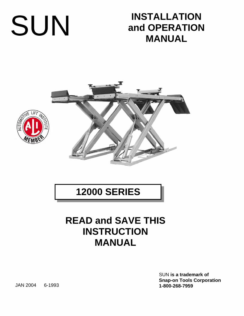
READ and SAVE THIS INSTRUCTION MANUAL JAN 2004 INSTALLATION and OPERATION MANUAL SUN 6-1993 SUN is a trademark of Snap-on Tools Corporation 1-800-268-7959 12000 SERIES
Transcript of SUN and OPERATION INSTALLATION MANUAL - Snap-on · 9.6 SPACE SAVER - OPTIONS PART LIST ... proper...
READ and SAVE THISINSTRUCTION
MANUAL
JAN 2004
INSTALLATION and OPERATION
MANUAL
SUN
6-1993
SUN is a trademark of Snap-on Tools Corporation1-800-268-7959
12000 SERIES

4
TABLE OF CONTENTS PAGE 1 IMPORTANT SAFETY INSTRUCTIONS........................................................................................................ 5 2 SPECIFICATIONS ............................................................................................................................................. 6 3 CONTENTS ........................................................................................................................................................ 7
3.1 Main Structural Components:...................................................................................................................... 7 3.2 Accessory Box Contents:............................................................................................................................. 7
4 TOOLS REQUIRED FOR INSTALLATION: ................................................................................................... 7 5 INSTALLATION INSTRUCTIONS .................................................................................................................. 7
5.1 BAY LAYOUT ........................................................................................................................................... 8 5.2 UNPACKING PROCEDURE..................................................................................................................... 9 5.3 HYDRAULIC INSTALLATION.............................................................................................................. 10 5.4 ELECTRICAL INSTALLATION............................................................................................................. 10 5.5 MECHANICAL SAFETY INSTALLATION .......................................................................................... 11 5.6 FRONT AND REAR TIE BAR INSTALLATION .................................................................................. 13 5.7 LEVELLING PROCEDURE .................................................................................................................... 13 5.8 ANCHORING PROCEDURE: ................................................................................................................. 15 5.9 INSTALLATION FOR ALIGNMENT MODEL...................................................................................... 15 5.10 INSTALLATION FOR ALL MODELS ................................................................................................... 16
6 INSTALLATION INSTRUCTIONS FOR THE 6000 LB. JACKING BEAM (Series 206 & 216)................. 17 7 OPERATING INSTRUCTIONS:...................................................................................................................... 17
7.1 RAISING THE LIFT:................................................................................................................................ 17 7.2 LOWERING THE LIFT:........................................................................................................................... 18
8 RECOMMENDED MAINTENANCE:............................................................................................................. 18 9 PARTS MANUAL ............................................................................................................................................ 20
9.1 12,000 LB SPACE SAVER ALIGNMENT.............................................................................................. 20 9.2 SPACE SAVER ALIGNMENT MAIN FRAME ASSEMBLY - PART LIST......................................... 21 9.3 12,000 LB SPACE SAVER SERVICE & RUST PROOFER................................................................... 22 9.4 SPACE SAVER MAIN FRAME ASSEMBLY, SERVICE & RUST PROOFER ................................... 23 9.5 12,000 LB SPACE SAVER OPTIONS..................................................................................................... 24 9.6 SPACE SAVER - OPTIONS PART LIST................................................................................................ 25 9.7 12,000 LB SPACE SAVER HYDRAULICS............................................................................................ 26 9.8 SPACE SAVER - HYDRAULICS PART LIST ....................................................................................... 27 9.9 12,000 LB SPACE SAVER POWER PACK............................................................................................ 28 9.10 12,000 LB SPACE SAVER POWER PACK - PARTS LIST................................................................... 29

5
1 IMPORTANT SAFETY INSTRUCTIONS
When using this lift, basic safety precautions should always be followed, including the following: 1. Read all instructions in this manual and on the lift. 2. Inspect lift daily. Do not operate if it malfunctions or problems have been encountered. 3. Never attempt to overload the lift. The manufacturer’s rated capacity is shown on the
identification label on the power side column. Do not override the operating controls or the safety devices.
4. Only trained and authorized personnel should operate the lift. Do not allow customers or bystanders to operate the lift or be in the lift area.
5. Caution! Never work under the lift unless the mechanical safety locks are engaged. 6. Always keep the lift area free of obstruction and debris. Grease and oil spills should
always be cleaned up immediately. 7. Never raise vehicle with passengers inside. 8. Before lowering check area for any obstructions. 9. To protect against the risk of fire, do not operate lift in the vicinity of open containers of
flammable liquids. 10. Adequate ventilation should be provided when working on internal combustion
engines.
SAVE THESE INSTRUCTIONS

6
SPACE SAVER 12000 SERIES
2 SPECIFICATIONS Maximum Capacity: 12,000 lbs. 5450 kg Overall Width: 92 inches 2337 mm Width Between Runways: 36 inches 914 mm Overall Length (172”W/B): 262-15/16 inches 6680 mm Max. Wheel base Alignment Model 172 inches 4368.8 mm Max. Wheel base Service Model 182 inches 4622.8 mm Max. Raised Height: 72 inches 1829 mm Min. Lowered Height: 8-3/4 inches 222 mm Lifting Time: 60 Sec. Power Requirements (Standard): 230 Volts, 1Ph., 60Hz. Shipping Weight ALIGNMENT Model 4980 lbs. 1615 kg Shipping Weight SERVICE Model 4750 lbs. 2154.56 kg

7
3 CONTENTS CHECK CONTENTS OF ACCESSORY BOX WITH PACKING LIST ENCLOSED IN BOX. The complete lift is contained in two (2) packages: 1. The main structural components are pre-assembled and packaged one on top of the other. 2. The remaining parts are packed in an accessory box.
3.1 Main Structural Components: 1pc. - Left Side Main Frame Assembly; Runway, Scissors and Base Frame 1pc. - Right Side Main Frame Assembly; Runway, Scissors and Base Frame Note: Hydraulic lines in base frames have been factory installed
3.2 Accessory Box Contents: Refer to list provided in accessories box. 4 TOOLS REQUIRED FOR INSTALLATION: * Rotary Hammer Drill or Similar, ¼" and ½” Concrete Drill Bits * 4' Level * SAE Wrenches and Sockets * Hammer (for anchor installation) * Pry Bar (for shim installation) * Chalk Line (for lift location) * Tape Measure * Side Cutters (to cut shipping straps) * Screw Drivers * Tube bender * Tube cutter * Flaring Tool (single flare) 37° JIC
* Hydraulic Fluid ISO 32 (10 weight hydraulic oil) - (20 liters / 5.3Gal.) * 25’ hose ¼” hydraulic hose, 3/8” JIC female fitting each end 5 INSTALLATION INSTRUCTIONS When the lift arrives on site, please read the owner’s manual completely. Check the contents to make sure no parts are missing before starting installation. Gather all the tools listed and make sure the installation instructions are fully understood before commencing with the installation.

8
IMPORTANT: It is the user’s responsibility to provide a satisfactory installation area for the lift. Lifts should only be installed on level concrete floors with a minimum thickness of five (5) inches or 130 mm. Concrete must have a minimum strength of 4000 psi or 30 MPa and should be aged thirty (30) days prior to installation. Please consult the architect, contractor or engineer if doubt exists as to the strength and feasibility of the floor to enable proper lift installation and operation. It is the user’s responsibility to provide all wiring for electrical hook-up prior to installation and to insure that the electrical installation conforms to local building codes. Where required, it is the user’s responsibility to provide an electrical isolation switch located in close proximity to the lift that will enable emergency stop capability and isolate electrical power from the lift for any servicing requirements.
5.1 BAY LAYOUT
Figure 2: Typical Bay Layout

9
IMPORTANT: DO NOT UNBOLT SHIPPING CLAMPS HOLDING EACH MAIN FRAME ASSEMBLY TOGETHER UNTIL INSTRUCTED TO DO SO. 1. After selecting the location best suited for your lift, draw a line parallel to the front of the lift, approximately 72” (1829mm) back from the cabinet/work bench area. This will be the approximate location of the front of the lift. Refer to Figure 2. NOTE: Check the installation area for obstructions. (Overhead; light fixtures, heating ducts, ceiling, and In-ground; floor drains, electrical, etc...) 2. Mark on the floor an outline matching the dimensions listed. SPACE SAVER - Alignment Model 12005: 172 inches (4369 mm) Wheel Base. 202 inches (5130.8mm)
x 92 inches (2336.8 mm). 12000 SERIES - Service Model 12006: 172 inches (4369mm) Wheel Base. 202 inches (5130.8 mm) x 92
inches (2336.8 mm). 3. Draw a center line down the middle of the outline starting at the front of the lift location and ending at the rear approach ramps. 4. Draw two lines parallel to the center line 20” (508mm) 12,000 lb., on either side to locate
the inside of the baseframes. 5. Draw a line parallel to the front of the lift or pit (flushmount) and align the front of each base
frame assembly onto this line. 172” (4369 mm) w/b: 38” ( 965.2 mm) back from the front of the lift.
6. Check the floor in the outline for the highest point using a four (4) foot level. Mark this
location, reference will be made to it later during the levelling procedure.
5.2 UNPACKING PROCEDURE 1. Cut and remove the metal banding straps that hold the accessory box (and sliding Jack Beams if so equipped) and place in a convenient location near the installation area. 2. Cut and remove the metal banding straps surrounding the Two Main Frame Assemblies. Position the Main Frame Assemblies in the location previously marked in the bay layout. NOTE: To distinguish between the left and right Main Frame Assemblies the pull-out step should be located at the front facing outward from the lift. All measurements are to be taken from the front of the lift. 3. Check that the inside of the base frames are 20" (508mm) away from the center line at both the front and rear of each mainframe assembly and that the front of each base frame is on the line drawn in step 5 of the bay layout, section 4.1.

10
5.3 HYDRAULIC INSTALLATION NOTE: When working with hydraulics it is important to keep all components clean. All hydraulic connections are 37 ½° JIC flares. 1. Select a position best suited for the power pack. 2. Remove the breather filler cap and fill with 20liters/5.3Gal. of ISO 32 hydraulic fluid. 3. Using a hydraulic tube bender, run a hydraulic line from the power pack to the hydraulic
inlet fitting located on the left side of the left base frame. After all the lines are cut and formed, install the nuts and sleeves, and then flare the ends of the tube.
4. If you have purchased the factory air kit option you should now cut and form the air supply line, from the lift to the desired location for customer connection to their shop air supply. The air supply line should have an operating pressure of 90-120psi (6-8 bar). 5. Tighten all the supply lines. You may now anchor the hydraulic power pack. (floor or wall mount). 6. Connect one end of the center hydraulic line to the outlet side of the left main frame
assembly and the other end to the inlet side of the right main frame assembly. Tighten the hydraulic line in place so that it runs along the floor giving it a low profile.
IMPORTANT: THE SHIPPING CLAMPS HOLDING EACH MAIN FRAME ASSEMBLY TOGETHER MUST BE UNBOLTED BEFORE CONNECTING ELECTRICAL POWER. THERE ARE TWO (2) CLAMPS ON EACH ASSEMBLY.
5.4 ELECTRICAL INSTALLATION IMPORTANT: ALL FINAL ELECTRICAL CONNECTIONS SHOULD BE MADE BY A QUALIFIED ELECTRICIAN. Please refer to Figure 3, the electrical diagram. Select a position for the remote hand control pendant to be hung from the ceiling. Hang in a position so the safety pedal may be easily reached. NOTE: THE CONTROL PENDANT SHALL BE INSTALLED IN SUCH A MANNER THAT THE CONTROL PENDANT CANNOT ENTER THE 18” HIGH LEVEL ABOVE THE FLOOR. (CLASS 1, DIVISION 2, HAZARDOUS LOCATIONS)

11
Figure 3: Electrical Schematic; 230 Volt, 1Ph., 60Hz. NOTE: Optional voltage and phase type power units will come with their own wiring diagram. IMPORTANT: WITH THE MAIN ELECTRICAL SUPPLY CONNECTED, PRESS THE UP CONTROL BUTTON TO RAISE THE LIFT 10” (254mm). STOP, THEN PRESS THE DOWN CONTROL BUTTON TO LOWER THE LIFT. REPEAT THIS PROCEDURE THREE (3) TIMES TO RELIEVE AIR FROM THE HYDRAULIC SYSTEM. CHECK FOR HYDRAULIC LEAKS AT ALL CONNECTIONS.
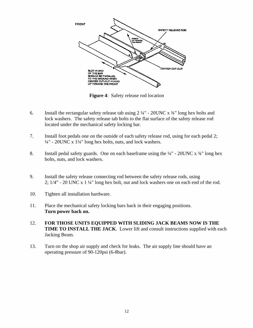
5.5 MECHANICAL SAFETY INSTALLATION 1. Locate the two (2) mechanical safety release rods and one (1) mechanical safety release connecting rod. 2. Raise the lift by pressing the up button on the hand control. 3. Turn off the power supply to the power pack. 4. Slide each mechanical safety release rod through the holes closest to the rear of each baseframe. 5. Slot in end of the bar should be parallel to the ground when center cut-out points up towards the front. Refer to Figure 4.
12
Figure 4: Safety release rod location
6. Install the rectangular safety release tab using 2 ¼" - 20UNC x ¾" long hex bolts and lock washers. The safety release tab bolts to the flat surface of the safety release rod located under the mechanical safety locking bar. 7. Install foot pedals one on the outside of each safety release rod, using for each pedal 2; ¼" - 20UNC x 1¼" long hex bolts, nuts, and lock washers. 8. Install pedal safety guards. One on each baseframe using the ¼" - 20UNC x ¾" long hex bolts, nuts, and lock washers. 9. Install the safety release connecting rod between the safety release rods, using 2; 1/4” - 20 UNC x 1 ¼" long hex bolt, nut and lock washers one on each end of the rod. 10. Tighten all installation hardware. 11. Place the mechanical safety locking bars back in their engaging positions. Turn power back on.
12. FOR THOSE UNITS EQUIPPED WITH SLIDING JACK BEAMS NOW IS THE TIME TO INSTALL THE JACK. Lower lift and consult instructions supplied with each Jacking Beam.
13. Turn on the shop air supply and check for leaks. The air supply line should have an operating pressure of 90-120psi (6-8bar).

13
5.6 FRONT AND REAR TIE BAR INSTALLATION 1. Raise lift to working height and lower onto safety. 2. Have 2; ½”-13UNC x 1½” long hex head bolts, flatwashers, lockwashers and nuts ready to support the tie bar when it is raised into place. 3. Raise the rear tie bar into place making sure the slotted holes are up and the nose-like protrusions are pointing toward the front of the units. The vertical members on the tube should be on the outside of the deck skirts. Line up each vertical section slot with the respective slot on the deck and place the bolts with washers through, one on each side. Put the flatwashers and lockwashers and nuts on the inside of the decks. DO NOT TIGHTEN! 4. Install 2; ½”-13UNC x 1½” long hex bolts, flatwashers and lockwashers to each end of the tie bar positioned under the deck. DO NOT TIGHTEN! 5. Now install the remaining 6; ½”-13UNC x 1½” long hex bolts, flatwashers, and lockwashers to the tie bar. DO NOT TIGHTEN! Baseframes should be level before tightening, Refer to leveling procedure (following section).
5.7 LEVELLING PROCEDURE NOTE: This is a very important procedure and time must be taken to do it correctly. 1. The highest point on the floor, noted from Section 4.1 step 6 is the point from which the
base frame will be levelled from. A quick check using a four (4) foot level across the base frame should again verify that this is the highest point.
2. Starting at the corner closest to the highest point, check along the length of the base frame edge with the four foot level and shim as required. NOTE THE FIVE CRITICAL POSITIONS THAT SHIMS MUST BE PLACED ON EACH BASE FRAME OF EACH MAIN FRAME ASSEMBLY. Refer to Figure 5. 3. Continue shimming across that base frame from side to side, and front to rear. 4. After levelling one frame completely, level the inside rails of the base frames to one another. 5. Now level the remaining outside half of the last base frame by placing the level across that unit and shimming as required. 6. A quick check across, along and between each base frame will ensure the levelling
procedure was carried out successfully. Re-adjust the tie bars if necessary. 7. Raise and lower the hoist completely several times. This allows the hoist to settle and
will ensure its proper operation. LEVELLING EXAMPLE: FIGURE 5

14
Assuming that the front right corner is the highest point level in the following order: - Shim along side “A” - Shim across from side “A” to side “B” (check along side “B” from front to back) The Right Side base frame should now be levelled. - Shim across from side “B” to side “C” (check along side “C” from front to back)
- Shim across from side “C” to side “D” (check along side “D” from front to back) - Shim along side E & side F (locking Mechanism)
Both base frames should now be levelled from front to back and side to side. NOTE: Base frame levelling should be performed as a reference before main levelling of the decks. One last check before anchoring is to make sure that there is 36” between the baseframes.
Figure 5: Levelling Procedure Example

15
5.8 ANCHORING PROCEDURE: 1. Using a rotary hammer drill and a ½" concrete drill bit, drill through the floor in the six (8) anchor bolt location holes positions on each of the base frames. Make sure that the ½" concrete drill is in good condition. Refer to Figure 6. 2. Insert the ½" x 4 ½" long wedge anchor bolts supplied, place a flat washer and nut on each anchor. Tighten securely. 3. Torque all anchor bolts to 55 ft. lbs. 4. With all anchor bolts torqued as specified operate the lift checking its full operation.
Figure 6: Anchoring
5.9 INSTALLATION FOR ALIGNMENT MODEL 1. Locate and install two (2) front wheel stops; one (1) to the front of each of the runways using six long hex head bolts, flat washers, lock washers, and nuts. NOTE: The lift has a front tie bar that must be installed before the front wheel stops are installed. 2. Unpack the levelling legs as marked on the leg and mounting hardware and place in their respective locations. NOTE: On the alignment model the REAR levelling
legs fold up toward the rear. The FRONT levelling legs towards the front. 3. Position but do not tighten all levelling leg brackets. The levelling legs should hang in
the brackets and swing freely. Thrust washers are provided to take up any side play in legs, install if required. Install thrust washers if there is more than 1/8”(3mm) clearance.
4. Check that legs hang perpendicular to the ground BEFORE tightening leg bracket bolts. 5. Lower the Space Saver lift down onto the levelling legs.
16
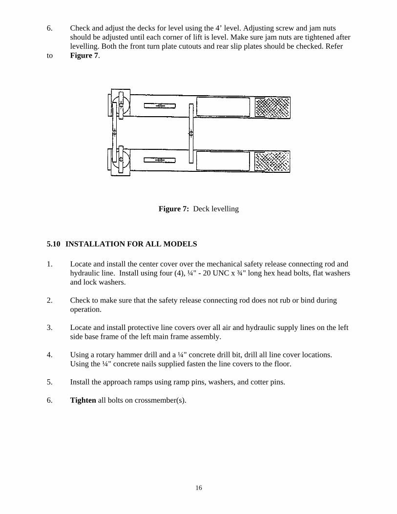
6. Check and adjust the decks for level using the 4’ level. Adjusting screw and jam nuts should be adjusted until each corner of lift is level. Make sure jam nuts are tightened after levelling. Both the front turn plate cutouts and rear slip plates should be checked. Refer to Figure 7.
Figure 7: Deck levelling
5.10 INSTALLATION FOR ALL MODELS 1. Locate and install the center cover over the mechanical safety release connecting rod and hydraulic line. Install using four (4), ¼" - 20 UNC x ¾" long hex head bolts, flat washers and lock washers. 2. Check to make sure that the safety release connecting rod does not rub or bind during operation. 3. Locate and install protective line covers over all air and hydraulic supply lines on the left side base frame of the left main frame assembly. 4. Using a rotary hammer drill and a ¼" concrete drill bit, drill all line cover locations. Using the ¼" concrete nails supplied fasten the line covers to the floor.
5. Install the approach ramps using ramp pins, washers, and cotter pins. 6. Tighten all bolts on crossmember(s).

17
6 INSTALLATION INSTRUCTIONS FOR THE 6000 LB. JACKING BEAM (Series 206 & 216)
1. Remove jacking beam from shipping carton. Remove the keeper brackets. Place the Jack Beam on the Space Saver hoist making sure the roller wheels are centered on the jacking beam track.
2. Raise the Space Saver hoist to a comfortable working height. Re-install the keeper
brackets located under the jacking beam. 3. Connect coiled air hoses supplied to the air inlet on the power pack for permanent
installation. Install ¼ NPT plugs or compatible air fitting to work with shop air tools to the extra outlets provided at the front and rear of the hoist.
4. Store the risers in holding brackets located on the top of the jacking beam. 5. All personnel operating the Space Saver jacking beam must be fully trained on its
operation as described by manufacturer. 7 OPERATING INSTRUCTIONS:
7.1 RAISING THE LIFT: 1. If the lift is equipped with Sliding Jack Beam(s) be sure that the Beam(s) are positioned at the front or mid travel of the lift, fully down, with the risers removed and stored. Never store Jack Beam(s) at the rear of the lift. 2. Be sure that the lift is fully lowered before attempting to load or unload a vehicle. 3. Position the vehicle on the lift ensuring the resulting load on each runway is as equal as possible. Under no circumstances should a vehicle be lifted if the weight distribution is unbalanced by 10% on either side of the center line between the runway. NOTE: The vehicle is positioned correctly when the distance from the center of the tires to the inside edge of the runways is equal on both runways, for the front and rear tires. 4. Check that there are no obstructions above the lift that could damage the lift or vehicles. 5. Raise the lift by pressing the up button on the remote pendant control. Raise the lift up, continue to raise, past the desired working height until the mechanical safety drops into position. Stop raising, now press the down button to lower the lift down onto both of the mechanical safeties. NOTE: NEVER WORK UNDER A VEHICLE OR THE LIFT UNLESS IT IS POSITIONED ON BOTH MECHANICAL SAFETIES!!!
18
7.2 LOWERING THE LIFT: 1. Check that there are no obstructions under the lift or vehicle. Be sure that the Sliding Jack Beams are fully lowered and positioned at the front or mid section of the lift. 2. Raise the lift by pressing the up button until the mechanical safety bars are off of their stops. Stop raising. 3. Depress the safety release pedal to disengage the mechanical safety locking bars. Continue to hold the pedal depressing the down button on the remote pendant control. 4. Continue lowering until the lift is approximately 34" (864mm) above the floor. Then release the mechanical safety release pedal, allowing the mechanical safety locking bars to be readied for their next use. Continue to depress the down button until the lift is completely lowered. NOTE: The operator must always keep their attention on the operation of the lift while raising or lowering. 5. Be sure that the lift is completely lowered before removing the vehicle from the lift. 8 RECOMMENDED MAINTENANCE: 1. Adjust level of lift daily. 2. The lift should be greased at least once every two months. There are six (6) points on each lift that will take grease: four (4) on the scissors hinges and one on each of the two (2) hydraulic cylinder rod eyelet’s. 3. The fluid level in the reservoir should be checked periodically. Be sure that the lift is fully lowered when checking. The hydraulic fluids should be changed once every five years. Use only ISO 32 hydraulic fluid. 4. The roller tracks should always be kept clean and free of debris. This area should be checked before any raising or lowering of the lift. 5. Inspect the operation of the lift daily. Raise and lower fully. 6. Inspect electrical and mechanical operations of all switches, electrical and mechanical. 7. Lifts equipped with full floating rear slip plates and front radius turning plates, require to be disassembled and cleaned once every 3 months. More frequently with lifts that are in areas with more exposure to sand and salt. NOTE: Locking pins should always be installed on front and rear plates before attempting to drive a vehicle on or off the lift.

19
8. If uneven lifting occurs as described in section 6.1.3 the crossmember(s) will need to be re-adjusted.
DO NOT ATEMPT TO LIFT A VEHICLE EXCEEDING THE LIFT’S RATED LIFT CAPACITY OF 12,000 LBS.
QUARTELY REAR SLIP PLATE MAINTENANCE 1. Remove top Slip Plate covers by first removing the four (4) shoulder bolts on each cover. 2. Remove polyethylene bearing cages insuring that all the delrin bearings remain in the
cages. Additional delrin bearings may be purchased if required. 3. Clean runway surface and touch up any paint wear with a rust resistant paint. Allow
paint to dry thoroughly. 4. To obtain optimum performance, the position of the slip plate bearing cage should be
rotated every quarter to change the wear pattern. With the first quarter maintenance, flip the bearing cage over to the opposite side. With the second quarter maintenance, rotate the bearing cage end-to-end. With the third quarter maintenance, flip bearing cage over to the opposite side. Fourth quarter maintenance should see the bearing cage rotated back to the position it started in.
5. Quarterly maintenance will optimize performance and contribute to longer slip plate life.

20
9 PARTS MANUAL
9.1 12,000 LB SPACE SAVER ALIGNMENT
05
09
34
43
06
09
43
32
10
02
07 47
33
30
37
29
13
28
20
48
47
12
08
03
46
17
10
33
14
17
18
01
27 25
24
10
40
27
26
27
23
49
35
44
11
09 36 39
16
42
41
19
21
23
40 31
45
28
27 26
15
04

21
9.2 SPACE SAVER ALIGNMENT MAIN FRAME ASSEMBLY - PART LIST ITEM QTY. DESCRIPTION PART # 1 1 BASE FRAME WELDMENT, LEFT SIDE 4-0160 2 1 BASE FRAME WELDMENT, RIGHT SIDE 4-0161 3 2 SCISSOR WELDMENT 4-0153 4 1 ALIGNMENT DECK, LEFT SIDE (172”W/B) 4-0158 5 1 ALIGNMENT DECK, RIGHT SIDE (172”W/B) 4-0159 6 2 APPROACH RAMP (172”W/B) 3-0285 7 2 WELDMENT, APPROACH RAMP PIN 1-0095 8 2 FRONT WHEEL STOP 2-0998 9 38 HEX BOLT, ½” - 13UNC X 1 ½”LG. 6-0291 10 32 HEX NUT, ½” - 13UNC 6-0035 11 38 LOCK WASHER, ½”I.D. 6-0059 12 2 LEVELLING LEG, FRONT-LEFT, REAR-RIGHT 3-0300 13 2 LEVELLING LEG, FRONT-RIGHT, REAR-LEFT 3-0299 14 4 PLUNGER PIN ASSEMBLY 2-0086 15 1 SAFETY RELEASE CONNECTING ROD 2-0071 16 4 FULCRUM PIN, 1 ¼” DIA. 1-0106 17 8 BUSHING, 1”I.D. 6-0630 18 8 END HINGE PIN, 1” DIA. 1-0107 19 4 CAM FOLLOWER, UPPER 6-0076 20 4 JAM NUT, 5/8” - 18UNF 6-0040 21 2 SAFETY BAR WELDMENT 2-1683 22 2 SAFETY PIN 1-0547 23 2 SAFETY PEDAL 2-0742 24 1 SAFETY RELEASE TAB 1-2280 25 1 SAFETY RELEASE ROD 2-0428 26 6 HEX BOLT, ¼” - 20UNC X 1 ¼”LG. 6-0027 27 14 LOCK WASHER, ¼”I.D. 6-0056 28 6 HEX NUT, ¼” - 20UNC 6-0032 29 1 CENTER COVER 3-0164 30 4 GREASE NIPPLE 6-0000 31 4 CAM FOLLOWER, LOWER 6-0077 32 1 REAR CROSSMEMBER WELDMENT 3-0297 33 16 FLAT WASHER, ½” I.D. 6-0439 34 1 FRONT CROSSMEMBER (172” W/B) 3-0298 35 2 TOE GUARD 1-0698 36 4 OUTSIDE LEG BRACKET 2-0118 37 16 WEDGE ANCHOR, ½” X 4 ½” LG 6-0140 38 4 CONCRETE NAIL, ¼” X 1” LG 6-0141 39 4 BUSHING, 1 ¼” I.D. 6-0084 40 14 COTTER PIN, 1/8” X 2” LG 6-0115 41 4 WASHER 1-0140 42 4 SPRING PIN, 3/16” X 2” LG 6-0146 43 6 FLATWASHER, ½” 6-0439 44 4 FLAT SHIPPING BRACKET 1-0728 45 4 CAP SCREW, HEX HEAD, ¼” – 20UNCX2 ½” LG 6-0554 46 4 HEX BOLT, ¼” – 20 UNC X 2 ½” LG 6-0554 47 8 JAM NUT, ¾” – 10UNC 6-0041 48 8 TAP BOLT, ¾” X 4” LG 6-0050 49 4 FLAT HEAD, ¼”-20UNC X ¾” LG. 6-1086

22
9.3 12,000 LB SPACE SAVER SERVICE & RUST PROOFER
09
39
31
05
30
02
06
30
10
36
07
04
36
09
08
15
14
20
01
25
41 24
15
03
37 35 38 13
27
16 17 36 19
28
26
12
10
30
33
23
24
25
40
24
23
32
29
21
34
24
22
18 41

23
9.4 SPACE SAVER MAIN FRAME ASSEMBLY, SERVICE & RUST PROOFER ITEM QTY. DESCRIPTION PART # 1 1 BASE FRAME WELDMENT, LEFT SIDE 4-0160 2 1 BASE FRAME WELDMENT, RIGHT SIDE 4-0161 3 2 SCISSOR WELDMENT 4-0153 4 1 SERVICE DECK, LEFT SIDE 4-0162 5 1 SERVICE DECK, RIGHT SIDE 4-0163 6 1 APPROACH RAMP 3-0285 7 2 RAMP PIN 1-0095 8 2 FRONT WHEEL STOP 2-0432 9 10 HEX BOLT 1/2-13UNC X 1-1/2”LG. 6-0291 10 22 HEX NUT 1/2”-13UNC 6-0035 11 14 LOCKWASHER 1/2” ID. 6-0059 12 1 SAFETY RELEASE CONNECTING ROD 2-0071 13 4 FULCRUM PIN, 1-1/4” DIA. 1-0106 14 8 BUSHING, BRONZE, 1”ID. 6-0630 15 8 END HINGE 1” DIA. 1-0107 16 4 CAM FOLLOWER 6-0637 17 4 JAM NUT, 5/8-18UNF 6-0040 18 2 SAFETY BAR WELDMENT 2-1683 19 2 SAFETY PINS 1-0547 20 2 SAFETY PEDAL 2-0742 21 2 SAFETY RELEASE TAB 1-2280 22 2 SAFETY RELEASE ROD 2-0428 23 6 HEX BOLT, 1/4-20UNC X 1-1/4”LG. 6-0027 24 14 LOCKWASHER, 1/4” 6-0056 25 8 HEX NUT, 1/4-20UNC 6-0032 26 1 CENTRE COVER 3-0371 27 4 GREASE NIPPLE 6-0000 28 4 CAM FOLLOWER 6-0077 29 1 REAR CROSSMEMBER WELDMENT 3-0297 30 22 1/2 SAE FLAT WASHER 6-0439 31 1 FRONT CROSSMEMBER 3-0298 32 2 TOE GUARD 1-0698 33 16 WEDGE ANCHOR 1/2” X 4-1/2”LG. 6-0140 34 4 CONCRETE NAIL 1/4 X 1”LG. 6-0141 35 8 BUSHING, 1 ¼” ID 6-0084 36 14 COTTER PIN 1/8” X 2” 6-0115 37 4 WASHER 1-0140 38 4 SPRING PIN, 3/16” X 2” LG 6-0146 39 6 WASHER, FLAT, ½” 6-0439 40 2 FLAT SHIPPING BRACKET 1-0728 41 4 CAP SCREW, HEX HEAD, ¼ - 20 UNC X 2 ½” LG 6-0554

24
9.5 12,000 LB SPACE SAVER OPTIONS
18
20 19
04
03
09
10
13
15
17
21
01
16
12
07
02
11
24
25
09
23 22
05
06
21
02
14
13
15 13
09
17
17

25
9.6 SPACE SAVER - OPTIONS PART LIST ITEM QTY. DESCRIPTION PART # 1 2 HOSE CLAMP HF - 5 6-0168 2 2 TERMINAL BOLT, 3/4”-16m W/1/4 NPT F 6-0167 3 8 FLAT WASHER 6-0426 4 8 SHOULDER BOLT, 3/8” X 5/8”LG. 6-0069 5 4 LOCKING PIN ASSEMBLY 2-0637 6 4 SELF TAP SCREW #10 X 1/2”LG. 6-0505 7 1 BULKHEAD, CHANGE 90 DEG. ELBOW C/W JAM NUT 6-0012 8 1 TUBE ASSEMBLY 3-0017 9 3 ADAPTER, 3/8”JIC M TO 1/4”NPT F 6-0118 10 1 HOSE ASSEMBLY 1-0119 11 1 TUBE ASSEMBLY 2-0062 12 1 SUPPLY TUBE, 3/8” X .049” X 20’LG. 6-0171 13 3 STREET TEE 1/4”NPT 6-0014 14 1 STREET ELBOW 1/4”NPT 6-0015 15 2 HOSE BARB FITTING, ¼” NPT 3/8” HOSE 6-0710 16 1 HOSE 144”W/B 1-0120 1 HOSE 172”W/B 1-0139 17 3 12’ COILED HOSE 6-0337 18 2 REAR SLIP PLATE WELDMENT 3-0197 19 1 SET (225) BALL BEARING 6-0829 20 2 REAR BEARING CAGE 3-0196 21 2 PLUG, 1/4”NPT 6-0282 22 4 TUBE CLAMP 6-0170 23 4 SELF TAP SCREW, #10 x 3/8”LG. 6-0169 24 2 TUBING SLEEVE, JIC 6-0017 25 2 TUBING NUT, 3/8” JIC 6-0016

26
9.7 12,000 LB SPACE SAVER HYDRAULICS

27
9.8 SPACE SAVER - HYDRAULICS PART LIST ITEM QTY. DESCRIPTION PART # 1 2 HYDRAULIC CYLINDER 3-0000 1-2 1 TUBE WELDMENT 2-0000 1-3 1 NUT GLAND 1-0011 1-4 1 GLAND 1-0008 1-5 1 ROD WELDMENT 2-0001 1-6* 1 WIPER RING 6-0001 1-7* 1 ‘O’ RING 6-0002 1-8 1 PISTON 1-0007 1-9* 1 SEAL RING 6-0003 1-10* 1 WEAR RING 6-0004 1-11 1 NYLON INSERT LOCK NUT, 7/8”-14UNF 6-0005 1-12 1 BEARING 6-0007 1-13 1 RETAINING RING 6-0070 1-14 1 GREASE NIPPLE 6-0000 15 2 PIN 1-0029 16 4 RETAINING RING 6-0340 17 2 VELOCITY FUSE 6-0422 18 2 TUBE ASSEMBLY, CYLINDER 1-0093 19 4 BULKHEAD, CONNECTOR 3/8”JIC C/W JAM NUT 6-0013 20 2 HOSE ASSEMBLY 2-2136 21 1 BULKHEAD ADAPTER, 3/8”BSF TO 3/8”JIC 6-0176 22 1 TUBE ASSEMBLY, RIGHT SIDE 2-0068 23 1 BULKHEAD, 90° ELBOW 3/8”JIC M C/W JAM NUT 6-0012 24 1 TUBE ASSEMBLY 2-0064 25 1 TUBE ASSEMBLY 2-0182 26 2 ADAPTOR, 3/8”BSF TO 3/8”JIC 6-0156 27 1 FLOW DIVIDER (WITH FITTINGS) 6-0173 28 1 TUBE ASSEMBLY 2-0066 29 4 LINE COVER 2-1104 30 1 SUPPLY TUBE 3/8” X .049”WALL X 20’ 6-0171 31 2 REDUCER NIPPLE, 3/8” TO 1/4” 6-0974 32 2 NUT, 3/8”TUBE 6-0016 33 16 CONCRETE NAIL, 1/4” x 1” 6-0141 34 1 TUBE ASSEMBLY 2-0519 35 2 ADAPTER, 90° EXTENDED 6-0174 36 2 SLEEVE 6-0017 *HYDRAULIC CYLINDER SEAL KIT PART # 0-0007
28
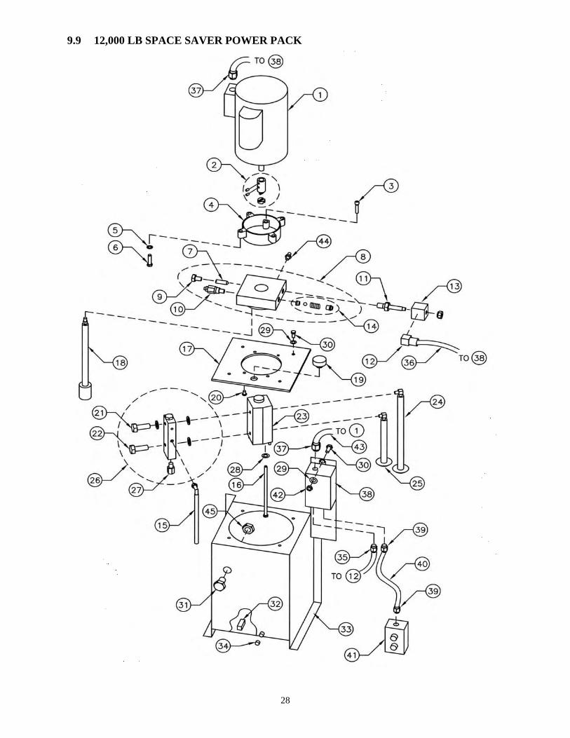
9.9 12,000 LB SPACE SAVER POWER PACK

29
9.10 12,000 LB SPACE SAVER POWER PACK - PARTS LIST
ITEM NO. QTY. DESCRIPTION PART NO. 1A 1 MOTOR, 220V, 1 PHASE 6-0087 1B 1 MOTOR, 220V, 3 PHASE 6-0446 1C 1 MOTOR, 575V, 3 PHASE 6-0447 2 1 MOTOR COUPLER 6-2537 3 2 CAP SCREW, SOCKETHEAD, 5/16”-18UNC x 1 ½” LG 6-2534 4 1 BELLHOUSING 6-2507 5 4 LOCKWASHER, INTERNAL TOOTH, 3/8” 6-2547 6 4 CAP SCREW, HEX HEAD, 3/8”-16UNC x 1 ½” LG 6-2558 7 1 FLOW CONTROL 1.5 – 2 GPM 6-2272 8 1 MAIN BODY ASSEMBLED (INCLUDING 7,9,10,14) 6-2518 9 1 PLUG, 3/8” (INCLUDES “O”-RING) 6-2519 10 1 RELIEF VALVE (5400 PSI) 6-2265 11 1 SPOOL VALVE 6-2505 12 1 DIN CONNECTOR 6-2503 13 1 COIL 220V RAC 6-2502 14 1 CHECK VALVE ASSEMBLY 6-2520 15 2 RETURN VALVE ASSEMBLY 6-2532 16 2 CAP SCREW, HEXHEAD, 5/16”-18UNC x 6 ½” LG 6-2533 17 1 MOUNTING PLATE 6-2521 18 1 RETURN FILTER ASSEMBLY 6-2522 19 1 FILLER / BREATHER CAP 6-2523 20 4 CAP SCREW, BUTTONHEAD, 5/16”-18UNC X ½” LG 6-2524 21 1 BANJO BOLT (C/W 2 WASHER SEALS) 6-2525 22 1 BANJO BOLT (C/W “O” – RINGS AND 1 WASHER) 6-2526 23 1 TANDEM PUMP 6-2527 24 1 LONG INLET STRAINER ASSEMBLY 6-2528 25 1 SHORT INLET STRAINER ASSEMBLY 6-2529 26 1 UNLOADING MANIFOLD ASSEMBLY 6-2530 27 1 BLEED OFF VALVE 6-2531 28 2 LOCKWASHER, 5/16” 6-0674 29 6 LOCKWASHER, ¼” 6-0056 30 6 CAP SCREW, HEX HEAD, ¼” – 20UNC X ¾” LG 6-0178 31 1 OIL LEVEL SIGHT PLUG 6-0517 32 1 MAGNET 6-0405 33 1 OIL RESERVOIR 4-0146 34 1 PLUG, SOCKETHEAD, 3/8” NPT 6-0102 35 1 ½” STRAIN RELIEF CONNECTOR 6-0092 36 3 FT COIL CABLE 8-0306 37 1 ½” STRAIN RELIEF CONNECTOR 6-1370 38A 1 CONTACTOR MOTOR STARTER 220V, 1 PHASE 6-0805 38B 1 CONTACTOR MOTOR STARTER 220V, 3 PHASE 6-0809 38C 1 CONTACTOR MOTOR STARTER 575V, 3 PHASE 6-0449 39 1 3/8” STRAIN RELIEF CONNECTOR 6-0093 40 1 REMOTE CONTROL CABLE 1-0103 41 1 REMOTE HAND CONTROL 6-0096 42 2 ¼” – 20UNC HEX NUT 6-0032 43A 1 MOTOR CABLE (1 PHASE) 1-0104 43B 1 MOTOR CABLE (3 PHASE) 1-1824 44 1 ADAPTOR (1/4” NPT MALE TO 3/8” JIC MALE) 6-0276

30
45 5 ½” CONDUIT LOCKNUT 6-1610 ***NOTE PUMP ASSEMBLY (INCLUDES 2 TO 28) 6-2238 COMPLETE POWERPACK ASSEMBLY 220V, 1 PHASE 0-0123 COMPLETE POWERPACK ASSEMBLY 220V, 3 PHASE 0-0767 COMPLETE POWERPACK ASSEMBLY 575V, 3 PHASE 0-0766

31