Summer Training Report - rakesh pandey
57
SUBMITTED IN PARTIAL FULFILLMENT OF THE REQUIREMENT FOR THE AWARD OF M. TECH DEGREE Report on Summer Training at ONGC Ankleshwar Asset By: Rakesh Kumar Pandey 14MT000287 Department of Petroleum Engineering, Indian School of Mines, Dhanbad
-
Upload
rakesh-pandey -
Category
Documents
-
view
639 -
download
4
Transcript of Summer Training Report - rakesh pandey

Innovation in EOR techniques Page
SUBMITTED IN PARTIAL FULFILLMENT OF THE
REQUIREMENT FOR THE AWARD OF M. TECH DEGREE
Report on
Summer Training at
ONGC Ankleshwar Asset
By:
Rakesh Kumar Pandey 14MT000287
Department of Petroleum Engineering,
Indian School of Mines, Dhanbad

Summer Training Report
ONGC Ankleshwar Asset Page | i
Table of Contents
1 Introduction ........................................................................................................................ 1
1.1 Cambay Basin ............................................................................................................. 1
1.2 Ankleshwar Asset ........................................................................................................ 5
1.2.1 Ankleshwar field .................................................................................................. 5
2 Well Logging ...................................................................................................................... 7
2.1 Introduction ................................................................................................................. 7
2.2 Types of log ................................................................................................................. 9
2.2.1 Open Hole Logging.............................................................................................. 9
2.2.2 Cased Hole Logging .......................................................................................... 10
2.3 Theory of Logging .................................................................................................... 10
2.3.1 Cement Bond Log (CBL-VDL) ......................................................................... 10
2.3.2 Sonic (CBL/VDL) Principle .............................................................................. 11
2.3.3 Production Logging ........................................................................................... 12
2.4 Interpretation of Open Hole Log ............................................................................... 15
2.4.1 Fundamentals of Log Interpretation................................................................... 15
2.4.2 Combinable Magnetic Resonace (CMR) ........................................................... 17
3 Well Services .................................................................................................................... 18
3.1 Introduction ............................................................................................................... 18
3.2 Workover ................................................................................................................... 19
3.2.1 What Is Workover .............................................................................................. 19
3.2.2 Fishing Operations ............................................................................................. 19
3.3 Well Completion and Testing ................................................................................... 25
3.3.1 Surface Equipments ........................................................................................... 25
3.3.2 Downhole equipments ....................................................................................... 27
3.4 Well Stimulation Services ......................................................................................... 31
3.4.1 Coiled tubing unit .............................................................................................. 31

Summer Training Report
ONGC Ankleshwar Asset Page | ii
3.4.2 Operations Performed By WSS Section ............................................................ 32
4 Crisis Management ........................................................................................................... 33
4.1 Kick ........................................................................................................................... 33
4.1.1 Causes of Kicks.................................................................................................. 34
4.2 Well Control Methods ............................................................................................... 34
4.3 Blowout Prevention Equipments ............................................................................... 34
Drilling Spools .................................................................................................................. 36
Diverter System .................................................................................................................... 36
Choke and Kill Lines............................................................................................................ 36
Choke Manifold.................................................................................................................... 36
Hydraulic Power Package (Accumulators) .......................................................................... 37
5 Artificial Lift ..................................................................................................................... 38
5.1 Electrical Submersible Pump .................................................................................... 39
5.2 Sucker Rod Pumping ................................................................................................. 41
5.3 Gas Lift ...................................................................................................................... 46
5.4 Hydraulic Pumping ................................................................................................... 48
5.5 Jet Pumping ............................................................................................................... 48
5.6 Progressive Cavity Pumping ..................................................................................... 49
5.7 Artificial Lift - Comparison ...................................................................................... 51
Summer Training Report
ONGC Ankleshwar Asset Page | iii
List of Figures
FIGURE 1: ROCK UNITS AND THEIR REFERENCE SECTION IN CAMBAY BASIN ................................ 2
FIGURE 2: LITHOSTRATIGRAPHY OF CAMBAY BASIN .................................................................... 3
FIGURE 3: TYPES OF TRAPS DISCOVERED IN CAMBAY BASIN ........................................................ 4
FIGURE 4:ANKLESHWAR ASSET .................................................................................................. 6
FIGURE 5: FIELD TRUCK .............................................................................................................. 7
FIGURE 6: OPEN HOLE TOOLS .................................................................................................... 10
FIGURE 7: CBL/VDL VARIATION .............................................................................................. 11
FIGURE 8: CALIPER TOOL .......................................................................................................... 15
FIGURE 9: EXAMPLE OF WELL LOG ............................................................................................ 16
FIGURE 10: SPIRAL GRAPPLE ..................................................................................................... 23
FIGURE 11: SPEARHEAD ............................................................................................................ 24
FIGURE 12: MILLING TOOLS ...................................................................................................... 24
FIGURE 13: TYPES OF PACKER ................................................................................................... 27
FIGURE 14: HYDRAULIC PACKER ............................................................................................... 30
FIGURE 15: SLIDING SLEEVE ..................................................................................................... 30
FIGURE 16: COILED TUBING UNIT .............................................................................................. 31
FIGURE 17: ANNULAR BOP ........................................................................................................ 35
FIGURE 18: ESP ........................................................................................................................ 40
FIGURE 19: CONVENTIONAL SRP ............................................................................................... 42
FIGURE 20: LUFKIN MARK II UNIT ............................................................................................. 43
FIGURE 21: SRP INSTALLATION SEQUENCE ............................................................................... 43
FIGURE 22: WALKING BEAM AND SAMSON POST ........................................................................ 44
FIGURE 23: COUNTERWEIGHTS ................................................................................................. 44
FIGURE 24: CRANKSHAFT ......................................................................................................... 45
FIGURE 25: SPECIFICATION OF SRP IN FIELD ............................................................................. 45
FIGURE 26: HORSEHEAD AND BRIDLE ....................................................................................... 46
FIGURE 27: JET PUMP ................................................................................................................ 49
FIGURE 28: PCP COMPONENTS .................................................................................................. 50

Summer Training Report
ONGC Ankleshwar Asset Page | iv
List Of Tables
TABLE 1: TYPES OF LOG AND APPLICATIONS ................................................................................ 8
TABLE 2: OPEN HOLE LOGS ......................................................................................................... 9
TABLE 3: KICK CONTROL .......................................................................................................... 33
TABLE 4: FACTORS FOR SELECTION OF ARTIFICIAL LIFT ............................................................. 38
TABLE 5: SELECTION CRITERIA FOR VARIOUS ARTIFICIAL LIFT TECHNIQUES .............................. 51

Summer Training Report
ONGC Ankleshwar Asset Page | v
Chapters 1 Introduction ........................................................................................................................ 1
2 Well Logging ...................................................................................................................... 7
3 Well Services .................................................................................................................... 18
4 Crisis Management ........................................................................................................... 33
5 Artificial Lift ..................................................................................................................... 38

Summer Training Report
ONGC Ankleshwar Asset Page | 1
1 Introduction
1.1 Cambay Basin
Discovery: 1958
Located on the western margin platform of Indian craton
Area 56,000 sq. km between 21° - 25°N and 71°30' - 79°30'E
Intracratonic basin in the form of N – S (NNW – SSE) trending graben flanked in the
East by Aravalli and Deccan Plateau and in the West by Saurashtra plateau
Age: Tertiary with mainly clastic sediments ranging from Eocene to Recent deposits
Two stage structure development
Earliest during Jurassic
Later during Late Cretaceous when Tertiary sedimentary basin came into
existence as a result of crustal tension following basaltic lava extrusion
Five tectonic blocks in the basin
Sanchar – Patan
Mehsana – Ahmedabad
Tarapur – Cambay
Jambusar – Broach
Narmada – Tapti
Stratigraphy
Basin is almost covered with Sabarmati alluvium, and alluvium of Mahisagar,
dadhar, Narmada, and Tapti rivers
Shallower towards north
8000m thick tertiary sediments overlie the Deccan Trap
Neogene succession comprises of six distinct units of sandstone And shale
Youngest unit, Jambusar formation (Pleistocene) is unconformably overlain by
Gujarat alluvium (Pleistocene / Holocene)

Summer Training Report
ONGC Ankleshwar Asset Page | 2
FIGURE 1: ROCK UNITS AND THEIR REFERENCE SECTION IN CAMBAY BASIN
Hydrocarbon habitat in Cambay Basin
Cambay Shale is the main source rock in this basin.
The organic matter content averages to 2.5% and mainly of sapropelic and humic
in nature.
The sandstone and siltstone of Ankleshwar, Kalol and Kadi Formations are the
main reservoir rocks in this basin.
The traps are structural, stratigraphic and combination type in this basin. Cambay
Shale acts as cap rock for hydrocarbon deposits in Kadi Formation and Vagad
Khol Formation, whereas in the northern part, Tarapur Shale acts as cap rock.
Telwa Shale of Ankleshwar Formation and Kanwa Shale in South of Mahisagar
river also serve as cap rock.

Summer Training Report
ONGC Ankleshwar Asset Page | 3
FIGURE 2: LITHOSTRATIGRAPHY OF CAMBAY BASIN

Summer Training Report
ONGC Ankleshwar Asset Page | 4
FIGURE 3: TYPES OF TRAPS DISCOVERED IN CAMBAY BASIN

Summer Training Report
ONGC Ankleshwar Asset Page | 5
1.2 Ankleshwar Asset
Ankleshwar is the first Asset where Oil and Natural Gas Corporation discovered oil in 1960.
It’s also the largest asset located in South of Gujarat in Bharuch district. Ankleshwar asset is
spread along Contiagal, Kosamba, Kim, Jalod, Rajpadi, Gandhar, Dahej, Nada, Kavi, Dabka,
Alamgir oil fields.
The Asset has two main fields: Ankleshwar field and Gandhar field. While Ankleshwar is a
mature field, Gandhar is a relatively new field which was discovered in 1984.
1.2.1 Ankleshwar field
Ankleshwar oil field is the biggest and the oldest oil-field of Oil and Natural Gas Corporation
Ltd. This is oil field is located at a distance of 6 km SSW of Ankleshwar Town in Gujarat
State. This field is situated in Narmada-Tapti Tectonic Block of Cambay Basin and having an
areal extent of 32.47 sq. km.
Geological Survey of India started exploration of oil and gas in the field as early as 1930’s.
Subsequently the geologists of Oil and Natural Directorate of India mapped the area and
carried out Gravity Magnetic Survey during the year 1957-1958. Seismic survey was carried
out in the year 1958-1959. An exploratory test well was released for confirming the
hydrocarbon potential and the well was drilled in the year 1960 to a depth of 1969 m.
Hydrocarbon accumulations have been discovered in arenaceous reservoirs within Cambay
shale, Ankleshwar, Dadhar and Babaguru formations. Major oil pools are found in multi-layer
sandstone reservoirs within Hazadand Ardol members of Ankleshwar formation. The
sandstones of Ankleshwar formation represent series of delta front sands of the pro Narmada
Delta developed in the South Cambay Basin.
1.2.1.1 About the Field
Field discovered in 1960.
Put on production since 1961.
Located at a distance of 15 km. from Ankleshwar town.
Part of Narmada Block of Cambay Basin.
Spread over an area of approx. 32.27 sq. km.
Hydrocarbon entrapment in multi-layered sandstone reservoir.
Summer Training Report
ONGC Ankleshwar Asset Page | 6
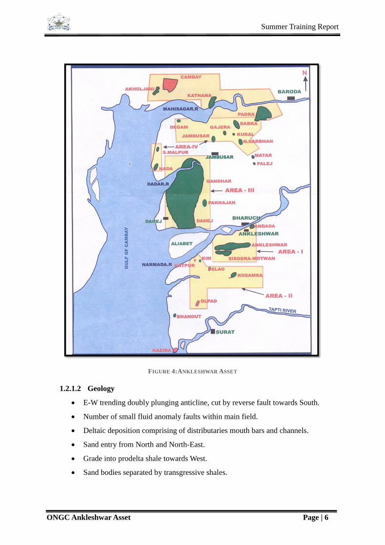
FIGURE 4:ANKLESHWAR ASSET
1.2.1.2 Geology
E-W trending doubly plunging anticline, cut by reverse fault towards South.
Number of small fluid anomaly faults within main field.
Deltaic deposition comprising of distributaries mouth bars and channels.
Sand entry from North and North-East.
Grade into prodelta shale towards West.
Sand bodies separated by transgressive shales.

Summer Training Report
ONGC Ankleshwar Asset Page | 7
2 Well Logging
2.1 Introduction
Well logging is a continuous and systematic recording of physical parameter versus depth in
borehole. The recorded information on film or paper is called a well log. Logs can also be
preserved in “CDs” or “DAT” tapes. Wireline logs or well logs are obtained by downhole
logging tools which are known as ‘Sonde’ lowered into the wells by means of a cable.
Measurements are transmitted up through the cable to a recording unit mounted on a logging
truck. The wire line logs are usually obtained after an interruption (or termination) of drilling
activity.
Geophysical well logging is necessary because core sample during drilling leaves a very less
record of formation encountered.
FIGURE 5: FIELD TRUCK

Summer Training Report
ONGC Ankleshwar Asset Page | 8
TABLE 1: TYPES OF LOG AND APPLICATIONS
Category
of Logs
Types of Log Parameter
Measured, Units
Application
Mechanical Caliper Diameter of hole The variation in diameter of a
borehole provides information on
the lithology, permeability and
porosity.
Electrical
S.P Spontaneous
potential mV/div
Correlation, Lithological indicator,
Determination of volume of shale
and formation water salinity,
Identification of porous and
permeable beds.
Focused tools Resistivity,
ohm-m
Effective determination of
formation resistivity.
Micrologs Resistivity, ohm-m Resistivity of mud cake,
Resistivity of invaded zone,
Induction Large,
medium and
small spacing
Conductivity of
formation
(millimhos/m)
Measurement of formation
resistivity
Nuclear Gamma Ray Natural
Radioactivity CPS
or API
Sensitive to presence of clay,
Correlation
Gamma –
Gamma
Reaction to Gamma
ray bombardment
CPS or API
Determination of Density and
Porosity
Neutron Reaction to Neutron
bombardment CPS
or API
Determination of Total Porosity
Acoustic Single or
Double
receiver
system
Transit time ,
Microsecond/foot
Porosity for valves greater
than 5 %

Summer Training Report
ONGC Ankleshwar Asset Page | 9
2.2 Types of log
Basically two types of logging are done:
Open hole logging
Cased hole logging
2.2.1 Open Hole Logging
Logs recorded in open hole are basically used for formation evaluation and identification of
lithology of the subsurface strata and estimating the thickness, porosity, permeability and
hydrocarbon saturation on the beds. This process is done after the drill string is pulled out
from the bore hole and before the casing is lowered inside.
TABLE 2: OPEN HOLE LOGS
Electrical logs Self Potential log
Resistivity log
Radioactive logs Gamma ray log
Neutron log
Density log
Other logs Sonic log
Temperature log
Caliper log
Dip meter log
Formation Tester (SFT or MDT)
Side wall core
Formation Micro resistivity image tool
(FMI)
Combinable Magnetic Resonance tool
(CMR)

Summer Training Report
ONGC Ankleshwar Asset Page | 10
2.2.2 Cased Hole Logging
The logging carried out in the cased wells is called Cased Hole Logging.
The main application of cased hole logging are:
1. Completion Services:
To see cement quality
Control log for perforation and other services
2. Reservoir monitoring:
To detect water flooding of any zone
To detect rise in fluid contacts
To locate bypass hydrocarbon
3. Production Logging:
To detect channelling behind casing
To detect contribution from different zones
To detect type of fluid produced
2.3 Theory of Logging
2.3.1 Cement Bond Log (CBL-VDL)
The cement bond tool consist of an acoustic transmitter, two receiver R1, R2 (3 feet , 5 feet)
CBL / VDL works on the principle of acoustic reflectivity.
FIGURE 6: OPEN HOLE TOOLS

Summer Training Report
ONGC Ankleshwar Asset Page | 11
The evaluation of cement bond quality comprises:
1. Evaluation of quality of cement behind pipe (amplitude in mV)
2. Evaluation of quality of cement to formation (VDL – Variable Density Log)
Micro or very thin fluid layer between casing and cement will give a high amplitude signal
corresponding to no contact, if casing is pressurised the micro annulus will close and low
amplitude will result. (The attenuation is inversely proportional to the casing thickness and
directly proportional to the solid density).
2.3.2 Sonic (CBL/VDL) Principle
As the sound travels at different velocities in different mediums, therefore their arrival times
to receiver will be different. The orders of these arrivals are:
1. The casing arrival
2. The formation arrival
3. The fluid arrival
These arrivals depend on the factors such as:
a. Formation velocities
b. Open hole size
c. Casing size
The basic bond log consists of an acoustic transmitter (or sound source) and an acoustic
receiver. The transmitter generates a sound pulse which travels through several different
sound paths to the receiver. The three most obvious paths observed are casing path, the
FIGURE 7: CBL/VDL VARIATION
Summer Training Report
ONGC Ankleshwar Asset Page | 12
formation path, and the fluid path. Because sound travels at different velocities in different
mediums, the sound waves from the three paths normally arrives at three different times.
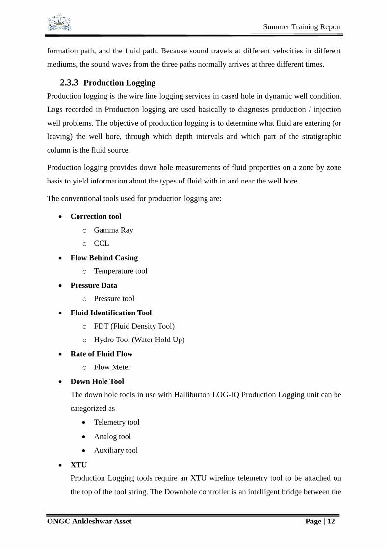
2.3.3 Production Logging
Production logging is the wire line logging services in cased hole in dynamic well condition.
Logs recorded in Production logging are used basically to diagnoses production / injection
well problems. The objective of production logging is to determine what fluid are entering (or
leaving) the well bore, through which depth intervals and which part of the stratigraphic
column is the fluid source.
Production logging provides down hole measurements of fluid properties on a zone by zone
basis to yield information about the types of fluid with in and near the well bore.
The conventional tools used for production logging are:
Correction tool
o Gamma Ray
o CCL
Flow Behind Casing
o Temperature tool
Pressure Data
o Pressure tool
Fluid Identification Tool
o FDT (Fluid Density Tool)
o Hydro Tool (Water Hold Up)
Rate of Fluid Flow
o Flow Meter
Down Hole Tool
The down hole tools in use with Halliburton LOG-IQ Production Logging unit can be
categorized as
Telemetry tool
Analog tool
Auxiliary tool
XTU
Production Logging tools require an XTU wireline telemetry tool to be attached on
the top of the tool string. The Downhole controller is an intelligent bridge between the
Summer Training Report
ONGC Ankleshwar Asset Page | 13
ultrawire tool bus and the Sondex Ultra link telemetry system. It serves both as a
communication interface and as a programmable logging controller.
The Purpose of the XTU Downhole controller is:
o To collect data from the tools on the Ultrawire tool bus and to transit this data to the
surface via the ultralink line automatically or under user control
o To facilitate bi directional communication between the surface and individual
ultrawire tools
o To convert high voltage DC power from the Ultralink line to supply the lower
voltage tools on the ultrawire tool bus
The tools those operate under the control of XTU telemetry:
QPC – Quartz Pressure & Casing Collar Locator Tool
PGR – Production Gamma Ray tool
FDR – Fluid Density Radioactive Tool
CTF – Capacitance, Temperature & Flow meter tool
1. QPC – Quartz Pressure & Casing Collar Locator Tool
It provides
A continuous log of borehole fluid pressure
A record of reservoir pressure draw down and build up data during flowing
tests
Location of casing collar for depth control
2. PGR – Production Gamma Ray tool
Production gamma detection provides
Lithology identification
Depth correlation
Identification of Radioactive scale, possible sign of water entry.
Monitoring of Radioactive flow tracer
3. FDR – Fluid Density Radioactive Tools
The purpose of the FDR is to fluid density of a sample as it flows through the tool. The
average density of this volume is measured whether the flow is single or multiphase.
Application:
Multiphase production profiling

Summer Training Report
ONGC Ankleshwar Asset Page | 14
Fluid Identification
High fluid flow rates
4. CTF – Capacitance, Temperature & Flow Meter Tool
Purpose: To provide a continuous log of fluid capacitance (water holdup), Temperature,
Flow rate and direction.
Application:
Fluid composition from average dielectric constant.
Location of leaks cross flow by temperature response.
Quantitative measurements of flow rate in casing & tubing.
Production and Injection log Interpretation.
Cement top determination.
Auxiliary Tools :
The auxiliary equipment provided with Production Logging Units
Roller Centralizer for centralization of tools in well.
Sinker Bar – to provide weight to the string for easy slide in the well.
Bull Nose – Required at string bottom in case CTF is not attached at the string
bottom.
Centralizer (Bow Spring) – to provide centralization for CBL tool in well.
2.3.3.1 Sonic or Acoustic Log
Sonic log is the measurement of acoustic wave propagation in the sub surface. The sonic
log is based upon the propagation of sound wave through the formation. The speed of the
sound wave depends upon the presence of fluid in the pores of rock. Thus the wave speed
or its travel time is a measure of formation porosity. It is also used for fracture
identification as well as for lithology identification.
Application:
To determine the porosity in the reservoir
To compute secondary porosity like vuggs in carbonate reservoir and fracture in
traps/basement
As an aid in lithological determination, when it combined with other porosity logs.
This can be used to study compaction in sand, shale sequence
Summer Training Report
ONGC Ankleshwar Asset Page | 15
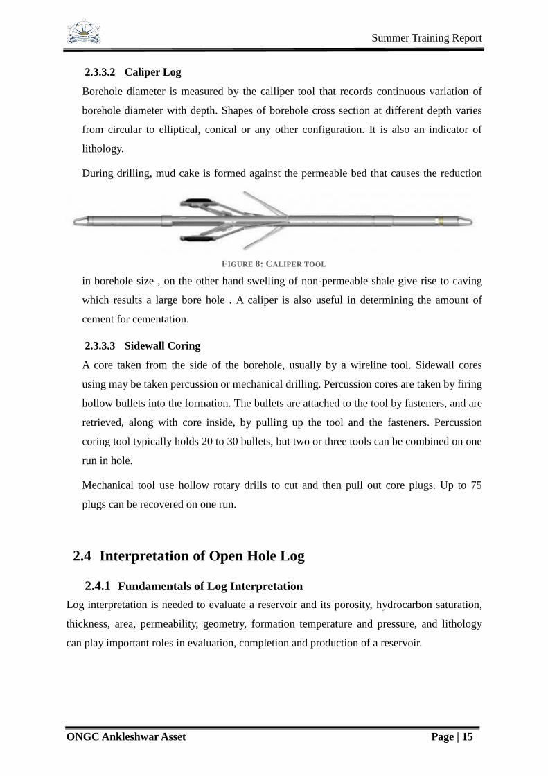
2.3.3.2 Caliper Log
Borehole diameter is measured by the calliper tool that records continuous variation of
borehole diameter with depth. Shapes of borehole cross section at different depth varies
from circular to elliptical, conical or any other configuration. It is also an indicator of
lithology.
During drilling, mud cake is formed against the permeable bed that causes the reduction
in borehole size , on the other hand swelling of non-permeable shale give rise to caving
which results a large bore hole . A caliper is also useful in determining the amount of
cement for cementation.
2.3.3.3 Sidewall Coring
A core taken from the side of the borehole, usually by a wireline tool. Sidewall cores
using may be taken percussion or mechanical drilling. Percussion cores are taken by firing
hollow bullets into the formation. The bullets are attached to the tool by fasteners, and are
retrieved, along with core inside, by pulling up the tool and the fasteners. Percussion
coring tool typically holds 20 to 30 bullets, but two or three tools can be combined on one
run in hole.
Mechanical tool use hollow rotary drills to cut and then pull out core plugs. Up to 75
plugs can be recovered on one run.
2.4 Interpretation of Open Hole Log
2.4.1 Fundamentals of Log Interpretation
Log interpretation is needed to evaluate a reservoir and its porosity, hydrocarbon saturation,
thickness, area, permeability, geometry, formation temperature and pressure, and lithology
can play important roles in evaluation, completion and production of a reservoir.
FIGURE 8: CALIPER TOOL

Summer Training Report
ONGC Ankleshwar Asset Page | 16
Above well log data shows different logs, Graph in first track shows Gamma ray response, its
deviation towards shows Sandstone, in second track gives Resistivity, high resistivity with
separation shows it may be the reservoir rock and corresponding low density and high
neutron log suggest that this bed is a reservoir rock containing Oil and Gas.
It is accomplished by determining the following parameters:
Detection of permeable beds and estimation of their true thickness
Determination of formation water resistivity, Rw
Determination of true formation water resistivity, Rt
Determination of true formation factor (F) and porosity (Φ)
Determination of water saturation (Sw)
Determination of effect of clay
Detection of presence of hydrocarbon in permeable bed
Estimation of porosity and water saturation
Tortuosity constant (a)
FIGURE 9: EXAMPLE OF WELL LOG
Summer Training Report
ONGC Ankleshwar Asset Page | 17
Cementation factor (m)
Saturation exponent (n)
2.4.2 Combinable Magnetic Resonace (CMR)
The high resolution CMR tool enhances the precision of nuclear magnetic resonance (NMR)
logging. Measurements for determining your reservoir’s permeability, water cut and
hydrogen pore volume are obtained at logging speeds 3 to 5 times faster than those of
conventional NMR tools. The result is much greater accuracy in productivity estimation
along with improved completion design for optimizing well performance and return on
investment.

Summer Training Report
ONGC Ankleshwar Asset Page | 18
3 Well Services
3.1 Introduction
Well services group is a pioneer in its field covering the entire gamut of activities consisting
of workover operations, well testing and completions and well stimulation services. Having a
strong and experienced man power of more than 700 persons, this group has rose to the
occasion to meet the multidimensional challenges in day to day activities with utmost
concern in safety aspects. This group comprises of three major sections viz. Work over
Section, well testing and well stimulation services.
Workover
The workover operation play the major role in sustaining the oil production from the mature
fields of eastern region. These operations are required for revival of sick oil, gas and water
injection and effluent disposal wells. The workover section is the flag ship of well services
group. Water shut off, zone transfer, casing repair, sand control jobs, servicing of of effluent
disposal wells, servicing of wells on artificial lifts, installation of artificial lifts systems etc.
Well completion and testing
This section comprises of well testing and downhole sections. Well testing is the first and
foremost major activity under taken after drilling a well success of which decides all future
oil production activities. All identified prospective objects are individually perforated and
completed using downhole equipments and the well is activated. Flow studies are then carried
out to measure the flow rates to estimate the reservoir potential. The wells are then suitably
completed and put in production.
Well stimulation services
Came into being in its present entity to fulfill the need of stimulation and specialized services
for enhancing oil and gas production.WSS provides stimulation services such as hydraulic
fracturing, acidization ,surfactant/solvent treatment and specialized services like coil tubing
services, gravel pack, nitrogen application, water shut off, hot oil circulation, sand gel plug,
tubular scouring and cleaning etc. This section has also actively participated in crises
management activities like blow out control, trouble shooting in trunk lines operations etc.

Summer Training Report
ONGC Ankleshwar Asset Page | 19
3.2 Workover
3.2.1 What Is Workover
The term workover is used to refer to any kind of oil well intervention operations i.e. the
workover operation includes one or more of a remedial operations on a producing well in
order to increase production.
Workovers rank among the most complex, difficult and expensive types of well work.
Workover operations are performed if the completion of a well is terminally unsuitable for
the job at hand, the production tubing may become damaged due to operational factors like
corrosion to the point where well integrity is threatened, downhole components such as
tubing, downhole retrievable safety valves or the artificial lift may have malfunctioned,
needing replacement or due to changing reservoir condition which make the completion
unsuitable.
Why Workover Is Necessary
To maintain the well in optimum producing condition.
Solving specific well and reservoir problems.
Workover operations performed
Through tubing perforation
Zone transfer
3.2.2 Fishing Operations
Fishing refers to the application of tools, equipment and techniques for removal of lost or
stuck objects from the well bore. The term “fishing” is taken from the times of the earlier
cable tool drilling when the crew simply put a hook on a line and attempted to catch the wire
line when it would break so that the tool could be retrieved. Over the years, with
advancement in drilling, completion and work over, fishing has also evolved greatly as an art
and science of removing broken or stuck equipment or small non-drillable materials from the
well bore.
The fishing operations can mainly be categorized into:
Open hole operations are those in which the fishing tools are run in open hole to
retrieve a fish present in open hole.
Cased hole wherein the fishing operations are carried out in cased hole.
Summer Training Report
ONGC Ankleshwar Asset Page | 20
Through tubing Through-tubing fishing takes place through the restriction of the
smaller-sized tubing. Through-tubing fishing applications have grown dramatically
with the increased use of coiled tubing as a conveyance method.
3.2.2.1 Fishing Tools
The key enabling technologies for successful fishing operations are cutting, milling,
catching/engaging and pulling.
Based on the kind of fishing operation, a variety of fishing tools are available. The use of
appropriate fishing tool for any particular job will largely depend on the type of fish in the
hole, whether the fish is stuck or free, whether it is in an open hole or in a cased hole, the
condition of the hole at the site of break and the condition of the top of the fish. Each fishing
job is unique but there are some basic tools such as safety joint, bumper sub, hydraulic jar
and heavy weight drill pipes that are used in most jobs along with appropriate fishing tool and
drill pipe work string. Based on intended application, the fishing tools can be classified into:
A. External Catch Tools
The external catch tools engage a fish on its outside body. Some of the commonly used
external catches fishing tools are:
i. Overshot
The overshot is one of the most widely used fishing tools. It is a highly versatile and efficient
tool. There are several different types of over shots; however, each overshot is designed to
engage a specific size of tubing, pipe, coupling tool joint, drill collar or smooth O.D tool. The
over shots are designated by a series number that indicates their application for fishing certain
types of fish e.g. Series 70. Over shots are used to release a fish with short space to engage
the tool on it. Similarly, Series150 over shots are used to release fish with sufficient neck
length and allow for circulation too.
Description of Tool
The basic overshot (from top down) consists of a top sub, a bowl, grapple, control and a
guide. In addition to the basic components, some over shots can be dressed with either:
Spiral Grapple – used if the fish diameter is near the maximum catch of the overshot.
Basket Grapple – used if the fish diameter is considerably below maximum catch size
(usually ½”)
Summer Training Report
ONGC Ankleshwar Asset Page | 21
Some times over shots are used with extension subs that are installed between the top sub and
the bowl of the overshot and extends the overshot bowl. Extension subs are used to either
establish a longer hold on a fish that may be undersize at the top by having been pulled in
two/ an overshot released several times or cover a bad section of pipe so that a tool joint can
be caught. Extension subs will only cover a fish O.D. equal to the maximum catch of the
overshot using a basket grapple and still remain full strength.
ii. Die Collar
The Die Collar is designed to retrieve tubular members from the well bore. The Die Collar is
manufactured from high-grade alloy and specially heat-treated. The hardened cutting teeth
(wickers) are machined on a shallow taper (approximately 3/4 inch per foot) to provide an
excellent grip and positive engagement. For operation, the tool is run to the fish top and
minimum weight and sufficient rotation is applied to allow the wicker threads to become
embedded in the exterior surface of the fish.
A major disadvantage of die collar is that the dis-engagement of die collar, in case the stuck-
up is not released, is extremely difficult and may further complicate the fishing operations.
B. Internal Catch Tools
The internal catch tools engage a fish on its inside body. Some of the commonly used internal
catches fishing tools are:
i. Taper Tap
The Taper Tap operates in an exactly opposite manner to a die collar and is basically
designed to retrieve tubular members from the well bore. It is the most economical tool of its
kind for freeing fish. The Taper Tap is also manufactured from high-grade alloy and specially
heat-treated. The basic Taper Tap is a single piece construction. The hardened cutting teeth
(wickers) are carbo-nitrided and machined on a shallow taper (approximately 3/4 inch per
foot) to provide an excellent grip for light duty pick-up jobs. For operation, the taper tap is
run to the top of fish and rotated sufficiently to allow the wicker threads to get embedded into
the interior surface of the fish.
ii. Grapple Releasing Spears
The grapple releasing spears are rugged, dependable and inexpensive tools used to retrieve
casings for side tracking purposes or tubing left due to free fall. The simple design assures
positive engagement throughout the fishing operation, is easy to release and re-engage if
necessary and may be run in conjunction with other equipment such as pack-off attachments
Summer Training Report
ONGC Ankleshwar Asset Page | 22
and internal cutting tools. The basic tool consists of a mandrel, a grapple, a bull nose nut and
a release ring.
C. Junk Catcher Tools
The junk catcher tools are used to remove junk/ debris from the well bore prior to/during
fishing/milling operations. Some of the commonly used such tools are:
i. Jet Basket
Jet basket is used to recover small objects such as bit cones, bearings, mill cuttings, broken
slips, hand tools and fragments of steel. Objects are forced into the basket by high-pressure
jets forcing fluid down the outside of the tool. The fluid exits through the tool I.D. moving
the object into the basket allowing the spring loaded catch fingers to catch the object.
The jet basket is usually made up in the fishing string below the drill collars in place of the
bit. The basket is lowered into the hole to a few feet off bottom and full circulation started
while slowly rotating the string to flush the hole of cuttings.
ii. Junk Basket
The junk basket is a highly successful fishing tool that incorporates a mill with double sets of
free finger type catchers. It will catch most small objects that may be dropped into the hole
including irregular objects. It is used to catch bit cones, slip fragments, wire line, hand tools
and other similar objects. Additional uses are to take core samples, drill full gauge holes or
ream. The manganese bronze catching fingers can be field dressed.
iii. Reverse Circulating Junk Basket
The conventional junk catchers employ forward/direct circulation at the bottom to lift the
cuttings and trap them. The distance to which the junk is to be lifted is normally more and
hence such tools are less effective.
In the Reverse Circulating Junk Basket also forward circulation is applied in the string that
gets converted to reverse circulation at the tool due to a ball. The RCJB is a better junk
catcher tool since the junk needs to travel a shirt distance only before it gets trapped in the
catcher sub. RCJB is used to remove objects such as slips, hand tools, bit cones and any other
small pieces of junk from bottom of well bore.
D. Accessory Tools
Various accessories are used in the fishing string. Some of them are:
i. Wire Catcher / Wire Line Spear
The wire line catcher is used to retrieve wire line.

Summer Training Report
ONGC Ankleshwar Asset Page | 23
ii. Fishing Magnet
The fishing magnet is used to retrieve all types of small objects having magnetic attraction
from the borehole bottom. Objects such as bit cones, bearings, slips, tong pins and mill
cuttings can often be retrieved only by magnetic attraction.
iii. Lead Impression Block (Lib)
The LIB is used to determine the configuration of fish top and to locate its position in the
well bore. The impression block is lowered on the end of the fishing string to approximately
5 feet above the fish. Circulation is used to clean the top of the fish and the string is then
rapidly slacked and set on fish with 15,000 to 20,000 pounds of weight on the fish to get a
good impression of fish top.
iv. Hydraulic Fishing Jar
The hydraulic fishing jar is used when a powerful upward blow is required to release the
stuck fish. The hydraulic jar is placed directly below the drill collars in the fishing string. The
intensity of each blow is controlled by the amount of stretch placed in the drill string. More
the pull harder is the blow. The jarring effect is enhanced by placement of drill collars above
the jar.
v. Bumper Sub
Bumper sub is used below hydraulic jar to prevent transmission of impact generated by jar to
tubing.
FIGURE 10: SPIRAL GRAPPLE

Summer Training Report
ONGC Ankleshwar Asset Page | 24
FIGURE 11: SPEARHEAD
FIGURE 12: MILLING TOOLS

Summer Training Report
ONGC Ankleshwar Asset Page | 25
3.3 Well Completion and Testing
3.3.1 Surface Equipments
3.3.1.1 Well Head Equipments
Wellhead equipments are attached to the top of the tubular goods used in a well
(API 6A)
o To support the tubular string and hang them.
o Seals between strings.
o Control production from the well.
They are permanent facilities after drilling is finished and resist high pressure and
do not leak being reliable and steady.
They should be corrosion resistant for wells producing H2S and C02.
Lowermost casing head
Lowermost Casing heads provide a secure connection between the surface casing and
the blowout preventer during drilling, and support the next casing string in the bowl
Features and Benefits
The bowl provides a load area, which must be able to support the casing hanger (mandrel or
slip type), the weight of the entire casing string, and the load from testing the wellhead
connection if no test protector is used.
Bottom connection - Slip-On-Weld and Buttress thread, with Base Plate are available.
Seal - The bowl provides a sealing area to isolate the annulus between the inside
diameter of the bowl and the outside diameter of the casing. The casing hanger, or a
separate seal assembly usually provides this seal.
Side outlets - Side outlets are available with line pipe thread and studded options. All
outlets are prepared for valve removal plugs
Intermediate Casing Head/ casing spool
It is a spool type unit or housing attached to the top flange of the underlying casing
head.

Summer Training Report
ONGC Ankleshwar Asset Page | 26
It is composed of:
A lower flange
One or two side outlet
An internal casing hanger bowl
A top flange where BOP or tubing head can be connected
Casing Hanger
The casing hanger is a wrap-around, slip-type, weight-set hanger. It may be installed
through the BOP and is suitable for heavy casing loads.
The hanger supports casing weight and seals the annulus before the BOP is removed.
Weight is supported on a solid shoulder not on seal; therefore, it will not over-
compress the seal.
The upper body diameter is larger to centralize and protect seals
The elastomer seal is mechanically activated by cap screws.
Casing Seal
The casing seal consists of elastomer chevron rings that seal against casing.
The seal is energized by injecting sealant into pressure rings.
Metal backup rings prevent pressure extrusion during thermal cycling.
Tubing Head/ tubing spool
Attached to the top flange of the uppermost casing head to provide a support for
tubing string.
Seal annular space between the tubing string and production casing string.
It is composed of:
A lower casing flange
One or two side outlets
Top flange with internal hanger bowl.
It has provision for anchor bolts to secure tubing hanger.
Tubing Hanger
It is used to provide a seal between the tubing and the tubing head or to support the
tubing and to seal between the tubing and tubing head.
Summer Training Report
ONGC Ankleshwar Asset Page | 27
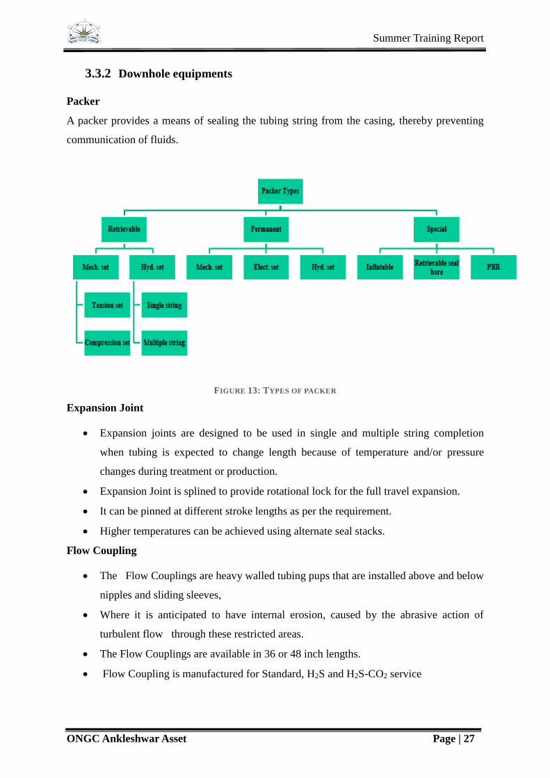
3.3.2 Downhole equipments
Packer
A packer provides a means of sealing the tubing string from the casing, thereby preventing
communication of fluids.
FIGURE 13: TYPES OF PACKER
Expansion Joint
Expansion joints are designed to be used in single and multiple string completion
when tubing is expected to change length because of temperature and/or pressure
changes during treatment or production.
Expansion Joint is splined to provide rotational lock for the full travel expansion.
It can be pinned at different stroke lengths as per the requirement.
Higher temperatures can be achieved using alternate seal stacks.
Flow Coupling
The Flow Couplings are heavy walled tubing pups that are installed above and below
nipples and sliding sleeves,
Where it is anticipated to have internal erosion, caused by the abrasive action of
turbulent flow through these restricted areas.
The Flow Couplings are available in 36 or 48 inch lengths.
Flow Coupling is manufactured for Standard, H2S and H2S-CO2 service
Summer Training Report
ONGC Ankleshwar Asset Page | 28
Blast Joint
Blast Joints are heavy walled tubing, run in the tubing string and positioned across
from a perforated interval where the jetting action of the fluid can erode the outside of
the tubing, thus prolonging the life of the completion.
A blast joint is also a length of tubing with enhanced wall thickness.
Landing Nipple
Landing nipple in the tubing string enables the installation of various control
equipment with wireline.
The landing nipple with their variety of profiles, allow the incorporation of an
unlimited number in a tubing string, with complete selectivity for setting and locking
of the appropriate mandrels.
The well may have atleast one landing nipple in the tubing string .It performs a dual
functions
It prevents the wireline tools larger than the no-go dimensions from being run
below the tubing.
It permits re-cocking of hydraulic jars when trying to open or close sleeves.
Sliding Sleeve
Sliding sleeves are part of tubing string and provide communication between the
tubing and the annulus.
Used for following application
Displacing fluids
Selective testing treating and production in multiple completion
Killing by circulation.
Pressure equalising
Install valve, choke and flow regulator in the nipple profile provided.
Side pocket mandrel
Side pocket mandrel has a polished receptacle/pocket at one side which receives down
hole tools lowered by wire line.
Side pocket mandrels can be positioned in the tubing string where it is necessary to
install
GLV
chemical injection valve

Summer Training Report
ONGC Ankleshwar Asset Page | 29
Hot oil injection valve
Chemical injection valve
Test or treat selectively
Provide communication between the tubing and annulus when required.
Pump Out Plug
A pump out plug is generally run at the bottom of the string and is used for
hydraulically setting the packer.
It has a seat to accommodate the ball & the seat is locked in position by shear screws
of specified shear value.
The ball dropped for setting the packer seats on the seat & ensure leak proof system.
After setting the packer, further pressurizing shears the shear screws the seat & ball
drops in to the sump.
Wire line re-entry guide
The wire line re-entry guide forms the bottom most part of the completion string and
is basically a mule shoe that is beveled to facilitate easy lowering & pulling of wire
line string through it.
Bridge Plug
A bridge plug is set in the casing to prevent the flow across that point in the casing.
It provides additional safety while the X-mas tree is being nippled up or nippled
down.
It may be permanent or retrievable.
Bridge plug can also be set between perforations to isolate the lower perforation while
the upper zone is squeezed cement, acidised or fractured.
They can be set either mechanically or by wireline.
Cement Retainer
The tool utilizes a production packing element design for effective sealing in the well
bore. During run-in, the packing element traps atmospheric pressure between itself
and the body.
As hydrostatic pressures increase, the tighter the element hugs the body, resulting in
higher run-in speeds without fear of swabbing.
Summer Training Report
ONGC Ankleshwar Asset Page | 30
Both the upper and lower slips are locked in position for safe tripping in the well
bore. When the slips are set in the casing, they encompass nearly the entire
circumference of the casing for maximum anchoring ability.
The retainer can be set by electric-line or mechanically.
Incorporated in the body design is a snap-in, snap-out buttress thread profile, resulting
in a low snap-in force.
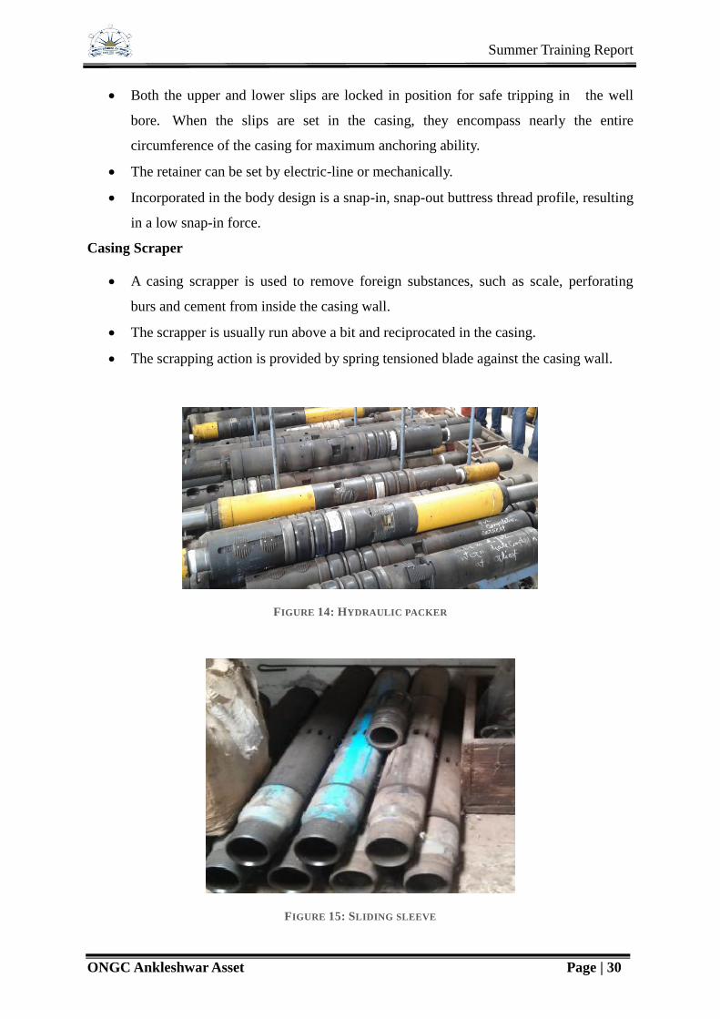
Casing Scraper
A casing scrapper is used to remove foreign substances, such as scale, perforating
burs and cement from inside the casing wall.
The scrapper is usually run above a bit and reciprocated in the casing.
The scrapping action is provided by spring tensioned blade against the casing wall.
FIGURE 14: HYDRAULIC PACKER
FIGURE 15: SLIDING SLEEVE

Summer Training Report
ONGC Ankleshwar Asset Page | 31
3.4 Well Stimulation Services
Intially or during the producing life of a well it may not produce as expected or may go off
production for many reasons. Well stimulation techniques are tools for improving or restoring
productivity. WSS came into being its present entity in 1983-84 to fulfil the need of
stimulation and specialized services for enhancing oil and gas production. WSS provides
services in following areas:
Acidization
Hydraulic fracturing
Specialized services
Coil tubing services
Nitrogen services
Sand control by gravel pack
Water shut off
Hot oil services
3.4.1 Coiled tubing unit
Coiled tubing is a well intervention method to deploy tools and equipments into a well.
FIGURE 16: COILED TUBING UNIT

Summer Training Report
ONGC Ankleshwar Asset Page | 32
Parts of Coiled Tubing Unit:
Tubing reel: In tubing reel, the coil tubing is spooled or stored.
Tubing Guiding Arch and Tubing Injector: Tubing guiding arch guides the coil tubing
from service reel to the injector chain present in the injector head. Tubing injector
controls the rate of lowering the tubing into the well under various well conditions. It
supports full weight of the tubing.
Stripper: Between BOP and injector head provides the primary operational seal
between pressurized wellbore fluids and the surface environments. It provides both
static and dynamic seal.
BOP: BOP of coil tubing unit is a quad ram BOP. It contains all the four rams- blind
ram, shear ram, slip ram and pipe ram.
3.4.2 Operations Performed By WSS Section
3.4.2.1 Dewaxing by Hot Oil Circulation Using Coiled Tubing Unit
The oil producing from the well was waxy crude oil. As the oil flows up the tubing, the
temperature decreases and wax started to deposit in the well bore. These gradually reduced
the inside diameter of the tubing and finally blocked the tubing. To resume production from
the wellbore first scrapping operation was conducted in the wellbore but when it was not so
effective, it was decided to perform hot oil circulation operation to melt the wax in the
wellbore. Coiled tubing was run into the well inside the tubing and the other end was
connected to the tanker where oil was heated to nearly 80 oF. Through the coiled tubing hot
oil was circulated. As soon as the wax was melted, oil from the bottom hole started to flow to
the surface.
3.4.2.2 Nitrogen Pumping Through Coiled Tubing Unit
Nitrogen pumping unit is taken to the site that contains two parts: a tank that contains liquid
nitrogen and a compressor unit. Coiled tubing is lowered into the well and using connections
nitrogen is pumped inside the tubing. Before injecting liquid nitrogen is converted to vapour
state and it is injected by using the compressor. The purpose of nitrogen pumping is
activation i.e. in order to remove the water head in the tubing to allow the flow from the
formation.

Summer Training Report
ONGC Ankleshwar Asset Page | 33
4 Crisis Management
4.1 Kick
A Kick is defined as an undesirable influx of formation fluid into the borehole. If left
unattended a kick can develop into a blowout (an uncontrolled influx of formation fluid into
the borehole).
While kicks are a problem, they are not too common. However, the penalty for failing to
control a kick can be the loss of the well, and quite possibly the loss of the rig and the lives of
the crew.
Well control procedures vary slightly from the rig to rig, and company to company, but four
simultaneous operations are normally considered.
TABLE 3: KICK CONTROL
Rig Control This includes the BOP's, pumps, draw works and other rig
equipment. This is the responsibility of the driller, and any blowout
control procedures should assign these operations to the driller.
Mud Control This involves the addition of weighting material (most commonly
barite) to the mud to increase its density, but also includes the
correct operation of the mixing system and chemical additions.
These are generally the responsibility of the mud engineer and
derrickman.
Choke Control This includes the correct calculation of pressures and time
relationships, as well as operating the choke and monitoring the
pump rate. The choke operator should be the best trained man on
the rig in kick control. He will be required to give guidance during
the kill operations.
Supervision This is the final element of control. This task will normally be
assigned to the rig superintendent or toolpusher. They will supervise
the previous three elements of well control operations.

Summer Training Report
ONGC Ankleshwar Asset Page | 34
4.1.1 Causes of Kicks
There are 4 major reasons why kicks occur:
Failure to keep the hole full
Swabbing of Formation Fluids into the Borehole
Insufficient Mud Density
Lost Circulation
4.2 Well Control Methods
Basically there are four methods of well control:
1. The Driller’s method (recommended when the Wait and Weight method cannot be
used for practical reasons).
2. The Wait and Weight method (recommended in most cases).
3. The Concurrent method (now an obsolete method).
4. The Volumetric method (required in special situation).
4.3 Blowout Prevention Equipments
The Blowout Prevention (BOP) equipment is the equipment which is used to shut-in a well
and circulates out an influx if it occurs. The main components of this equipment are the
Blowout Preventers or BOP’s. These are valves which can be used to close off the well at
surface. In addition to the BOP’s, the BOP equipment refers to the auxiliary equipment
required to control the flow of the formation fluids and circulate the kick out safely.
There are 2 basic types of BOP used for closing in a well:
a) Annular (bag type)
b) Ram type
It is very rare for only one BOP to be used on a well. Two, three or more preventers are
generally stacked up, one on top of other to make up a BOP stack. This provides greater
safety and flexibility in the well control operation.
a) Annular Preventers
The main component of the annular BOP is a high tensile strength, circular rubber packing
unit. The rubber is mounted around a series a metal ribs. The packing unit can be compressed
inwards against drillpipe by a piston, operated by hydraulic power.

Summer Training Report
ONGC Ankleshwar Asset Page | 35
The advantage of such a well control device is that the packing element will close of around
any size or shape of pipe. An annular preventer will also allow pipe to be stripped in (run into
the well while containing annulus pressure) and out and rotated, although its service life is
much reduced by these operations.
b) Ram Type Preventers
Ram type preventers derive their name from the twin ram elements which make up their
closing mechanism. Three types of ram preventers are available:
i. Blind rams – which completely close off the wellbore when there is no pipe in the
hole.
ii. Pipe rams – which seals off around a specific size of pipe thus sealing off the
annulus.
iii. Shear rams – which are the same as blind rams except that they can cut through
drillpipe for emergency shut-in but should only be used as a last resort. A set of
pipe rams may be installed below the shear rams to support the severed drillstring.
FIGURE 17: ANNULAR BOP

Summer Training Report
ONGC Ankleshwar Asset Page | 36
Drilling Spools
A drilling spool is a connector which allows choke and kill lines to be attached to the BOP
stack. The spool must have a bore at least equal to the maximum bore of the uppermost
casing spool. The spool must also be capable of withstanding the same pressures as the rest of
the BOP stack.
Diverter System
The diverter is a large, low pressure, annular preventer equipped with large bore discharge
flowlines. This type of BOP is generally used when drilling at shallow depths below the
conductor. If the well were to kick at this shallow depth, closing in and attempting to contain
the downhole pressure would probably result in the formations below the conductor
fracturing and cratering of the site or at least hydrocarbons coming to surface outside of the
conductor string. The purpose of a diverter is to allow the well to flow to surface safely,
where it can be expelled safely expelled through a pipeline leading away from the rig.
Choke and Kill Lines
When circulating out a kick the heavy fluid is pumped down the drillstring, up the annulus
and out to surface. Since the well is closed in at the annular preventer the wellbore fluid leave
the annulus through the side outlet below the BOP rams or the drilling spool outlets and pass
into a high pressure line known as the choke line. This choke line carries the mud and the
influx from the BOP stack to the choke manifold. The kill line is a high pressure pipeline
between the side outlet, opposite the choke line outlet, on the BOP stack and the mud pumps
and provides a means of pumping fluids downhole when the normal method of circulating
down the drillstring is not possible.
Choke Manifold
The choke manifold is an arrangement of valves, pipelines and chokes designed to control the
flow from the annulus of the well during a well killing operation. It must be capable of:
a) Controlling pressures by using manually operated chokes or chokes operated from a
remote location.
b) Diverting flow to a burning pit, flare or mud pits,
c) Having enough back up lines should any part of the manifold fail.
d) A working pressure equal to the BOP stack.

Summer Training Report
ONGC Ankleshwar Asset Page | 37
Hydraulic Power Package (Accumulators)
The opening and closing of the BOP is controlled from the rig floor. The control panel is
connected to an accumulator system which supplies the energy required to operate all the
elements of the BOP stack. The accumulator consists of cylinders which store hydraulic oil
at high pressure under a compressed inert gas (nitrogen). When the BOPs have to be closed
the hydraulic oil is released (the system is designed to operate in less than 5 seconds).
Hydraulic pumps replenish the accumulator with the same amount of fluid used to operate the
preventers. Another function of the accumulator unit is to maintain constant pressure while
the pipe is being stripped through the BOPs.

Summer Training Report
ONGC Ankleshwar Asset Page | 38
5 Artificial Lift
Artificial lift refers to the use of artificial means to increase the flow of liquids, such as crude
oil or water, from a production well. Generally this is achieved by the use of a mechanical
device inside the well (known as pump or velocity string) or by decreasing the weight of the
hydrostatic column by injecting gas into the liquid some distance down the well. Artificial lift
is needed in wells when there is insufficient pressure in the reservoir to lift the produced
fluids to the surface, but often used in naturally flowing wells (which do not technically need
it) to increase the flow rate above what would flow naturally. The produced fluid can be oil,
water or a mix of oil and water, typically mixed with some amount of gas.
The types of artificial lift available are:
1) Gas lift -continuous gas lift
-intermittent gas lift
2) Sucker rod pumping
3) Electrical submergible pumping
4) Progressive cavity pumping
5) Jet pumping
There are various factors upon which a selection of artificial method depends.
TABLE 4: FACTORS FOR SELECTION OF ARTIFICIAL LIFT
Sucker rod
pumping
Gas lifting Electrical
submergible
pumping
Operating depth 100’ -16000” TVD 5000’-15000’ TVD 1000’-15000’TVD
Operating volume 5-5000 BPD 200-30000 BPD 200-30000 BPD
Operating
temperature
100-550 0F 100-400 0F 100-400 0F
Fluid gravity >80 API >150API >100 API
Offshore
application
Limited Excellent Excellent
Solid handling Fair to good Poor Poor to fair
Overall system
efficiency
45%-60% 10%-40% 35%-60%

Summer Training Report
ONGC Ankleshwar Asset Page | 39
Most important factors for choice of lift modes:
For very high volume of production - GL, ESP or HP
For very low volume of production - SRP or IGL
For moderate volume of production - GL, ESP, HP or SRP
For very deep well of production - HP
5.1 Electrical Submersible Pump
An artificial-lift system that utilizes a downhole pumping system that is electrically driven.
The pump typically comprises several staged centrifugal pump sections that can be
specifically configured to suit the production and wellbore characteristics of a given
application. Electrical submersible pump systems are a common artificial-lift method,
providing flexibility over a range of sizes and output flow capacities.
The Electric Submersible Pump System consists of several components that are carefully
selected to combine into the most economical and efficient solution for each set of well
conditions.
1. Surface Equipment
2. Power Cable
3. Motor Lead Extension
4. Pump: The pumping unit itself consists of the multi-stage centrifugal pump housed in
a pressure sleeve with the capability of producing capacities up to 50.000 BPD from
depths of up to 13.900 ft.
5. Gas Separator/Intake: Immediately under the pump is the intake combined with a gas
separator if required. The gas separator allows for trouble free operation in well
conditions with free gas contents of more than 10%.
6. Motor: The high quality electrical motor (6) for well casings 41/2" and larger is a
squirrel cage, two pole, three phase induction motor. The motor turns at a speed of
approximately 3500 RPM at 60 Hz and 2900 RPM at 50 Hz power source.
7. Sensor: The down hole sensor is located below the motor and transmits important
well and system data via the main power cable to the surface.

Summer Training Report
ONGC Ankleshwar Asset Page | 40
8. Protector: Located between motor and pump intake is the protector. The protector
isolates the motor from the well fluid and contains the high capacity thrust bearing.
9. Check Valve & Drain Valve: Other protective devices are located above the pump
discharge: The check valve that closes on shut down of the unit and prevents back
spinning and the drain valve that allows for pulling the ESP without a wet tubing
string.
Working Operation of ESP
FIGURE 18: ESP
Electric Submersible Pumping Systems incorporate an electric motor and centrifugal pump
unit run on a production string and connected back to the surface control mechanism and
transformer via an electric power cable. The downhole components are suspended from the
production tubing above the wells' perforations. In most cases the motor is located on the

Summer Training Report
ONGC Ankleshwar Asset Page | 41
bottom of the work string. Above the motor is the seal section, the intake or gas separator,
and the pump. The power cable is banded to the tubing and plugs into the top of the motor.
As the fluid comes into the well it must pass by the motor and into the pump. This fluid flow
past the motor aids in the cooling of the motor. The fluid then enters the intake and is taken
into the pump. Each stage (impeller/diffuser combination) adds pressure or head to the fluid
at a given rate. The fluid will build up enough pressure as it reaches the top of the pump to
lift it to the surface and into the separator or flowline. Electric submersible pumps are
normally used in high volume (over 1,000 BPD) applications.
5.2 Sucker Rod Pumping
Introduction
Sucker rod pumping is also referred to as ‘‘beam pumping.’’ It provides mechanical energy to
lift oil from bottom hole to surface. It is efficient, simple, and easy for field people to operate.
It can pump a well down to very low pressure to maximize oil production rate. It is applicable
to slim holes, multiple completions, and high-temperature and viscous oils. The system is
also easy to change to other wells with minimum cost. The major disadvantages of beam
pumping include excessive friction in crooked/ deviated holes, solid-sensitive problems, low
efficiency in gassy wells, limited depth due to rod capacity, and bulky in offshore operations.
Beam pumping trends include improved pump-off controllers, better gas separation, gas
handling pumps, and optimization using surface and bottom-hole cards.
Pumping System
A sucker rod pumping system consists of a pumping unit at surface and a plunger pump
submerged in the production liquid in the well. The prime mover is either an electric motor or
an internal combustion engine. The modern method is to supply each well with its own motor
or engine. Electric motors are most desirable because they can easily be automated. The
power from the prime mover is transmitted to the input shaft of a gear reducer by a V-belt
drive. The output shaft of the gear reducer drives the crank arm at a lower speed (4–40
revolutions per minute [rpm] depending on well characteristics and fluid properties). The
rotary motion of the crank arm is converted to an oscillatory motion by means of the walking
beam through a pitman arm. The horse’s head and the hanger cable arrangement is used to
ensure that the upward pull on the sucker rod string is vertical at all times (thus, no bending
moment is applied to the stuffing box). The polished rod and stuffing box combine to
Summer Training Report
ONGC Ankleshwar Asset Page | 42
maintain a good liquid seal at the surface and, thus, force fluid to flow into the ‘‘T’’
connection just below the stuffing box.
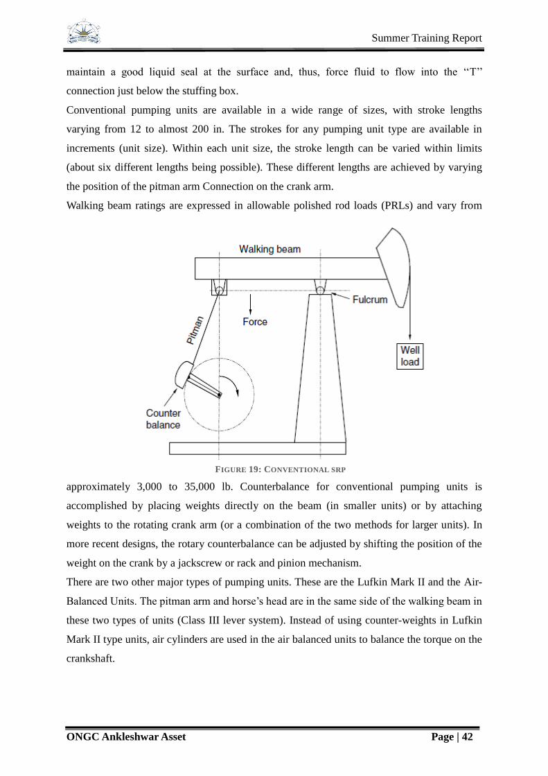
Conventional pumping units are available in a wide range of sizes, with stroke lengths
varying from 12 to almost 200 in. The strokes for any pumping unit type are available in
increments (unit size). Within each unit size, the stroke length can be varied within limits
(about six different lengths being possible). These different lengths are achieved by varying
the position of the pitman arm Connection on the crank arm.
Walking beam ratings are expressed in allowable polished rod loads (PRLs) and vary from
approximately 3,000 to 35,000 lb. Counterbalance for conventional pumping units is
accomplished by placing weights directly on the beam (in smaller units) or by attaching
weights to the rotating crank arm (or a combination of the two methods for larger units). In
more recent designs, the rotary counterbalance can be adjusted by shifting the position of the
weight on the crank by a jackscrew or rack and pinion mechanism.
There are two other major types of pumping units. These are the Lufkin Mark II and the Air-
Balanced Units. The pitman arm and horse’s head are in the same side of the walking beam in
these two types of units (Class III lever system). Instead of using counter-weights in Lufkin
Mark II type units, air cylinders are used in the air balanced units to balance the torque on the
crankshaft.
FIGURE 19: CONVENTIONAL SRP

Summer Training Report
ONGC Ankleshwar Asset Page | 43
The American Petroleum Institute (API) has established designations for sucker rod pumping
units using a string of characters containing four fields. For example,
C---228D---213---120
The first field is the code for type of pumping unit. C is for conventional units, A is for air-
balanced units, B is for beam counterbalance units, and M is for Mark II units. The second
field is the code for peak torque rating in thousands of inch-pounds and gear reducer. D
stands for double-reduction gear reducer. The third field is the code for PRL rating in
hundreds of pounds. The last field is the code for stroke length in inches.
FIGURE 20: LUFKIN MARK II UNIT
SRP Installation
FIGURE 21: SRP INSTALLATION SEQUENCE
STRUCTURE
CRANKSHAFT
SKID
HORSE HEAD
COUNTER WEIGHT
SAMPSON POST
HOOK UP WITH POLISHED ROD
MOTER SKID

Summer Training Report
ONGC Ankleshwar Asset Page | 44
FIGURE 22: WALKING BEAM AND SAMSON POST
FIGURE 23: COUNTERWEIGHTS

Summer Training Report
ONGC Ankleshwar Asset Page | 45
FIGURE 24: CRANKSHAFT
FIGURE 25: SPECIFICATION OF SRP IN FIELD
Summer Training Report
ONGC Ankleshwar Asset Page | 46
5.3 Gas Lift
Gas Lift Classification
Broadly the Gas Lift operation can be classified into two types depending upon their mode of
operation.
1. Continuous Gas Lift
2. Intermittent Gas Lift
Continuous Gas Lift
In continuous flow operations a continuous volume of high pressure is injected through the
educator tube to lighten or aerate a column of fluid which allows sufficient pressure
differential across the sand face causing the well to produce at a desired rate of flow. To
obtain this a flow valve is used which allows the deepest one point injection of the available
Gas Pressure in conjunction with a valve that acts as a variable valve with a changing orifice
which controls the rate of Gas Injection at the surface.
Continuous Lift can be used in wells exhibiting the following characteristics:
Wells with a high PI
Wells having a reasonably high bottom hole pressure (BHP)
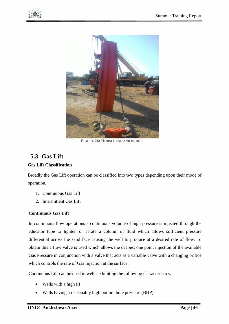
FIGURE 26: HORSEHEAD AND BRIDLE

Summer Training Report
ONGC Ankleshwar Asset Page | 47
Intermittent Gas Lift
Intermittent Flow involves the expansion of a high pressure gas ascending to a low pressure
outlet. A valve provides complete volume and pressure expansion control of the gas entering
into the tubing thus either regulating the lift of the column of fluid above the valve position
with maximum velocity to minimize fluid slippage or controlling liquid fall-back and also
delivering fluid to the outlet tank with minimum gas. It is used in conjunction with a surface
time cycle controller or an intermitter.
Intermittent Gas Lift can be applied to wells having the following characteristics:
1. High PI with low bottom hole pressure.
2. Low PI with low bottom hole pressure.
In intermittent Gas Lift, gas is injected at regular intervals into the casing annulus by using an
intermitter. Intermitter is a motor valve operated with a connecting timing device which
allows selective cycling and controlled gas injection into the casing annulus.
However there are installations in which intermittent gas lift is obtained without the use of a
surface intermitter. These types of installations require a valve that is somewhat more fluid
sensitive than normal and requires a built in spread.
Use of this type of valves may present problems where fluid must be lifted overlong flow-
lines against surface chokes and in situation where sensitivity of the valves may become a
disadvantage.
Intermittent Gas Lift can also be accomplished using multi-point injection of gas using
multiple Gas Lift Valves. This type of installation must be designed such that the lowest Gas
Lift Valves open just as the slug passes each valve.
Injection Rates
In independent studies conducted by investigators on Gas Lift efficiency, 4 types of Gas
Injection Rates were found which were significant in any Gas Lift installations. These were
as following:
Injection Rates for no flow at extremely low injection rates. If the gas is injected at
extremely low rate, it rises to the surface in form of small hemispheres flat at the
bottom.
Injection Rate of Maximum efficiency where minimum volume of gas is required to
loft 1 barrel of oil.

Summer Training Report
ONGC Ankleshwar Asset Page | 48
Injection Rate of maximum production. This the volume of gas required for
maximum production.
Injection Rate of no flow due to excess Gas Injection, which is reached when the
friction produced by the gas prevents the Liquid from entering the tubing
5.4 Hydraulic Pumping
Hydraulic Pumping systems consist of the following
a) Surface Power Fluid system
b) Prime Mover
c) Surface Pump
d) Downhole Jet or Reciprocating Pump
In hydraulic pumping system, a hydraulic engine-pump assembly is attached at the bottom of
the production tubing. The unit is installed in the well below the working fluid level. A high
pressure power fluid, liquid oil whose pressure is build up by a surface pump, is pumped
down to the engine from the surface. The power fluid drives the hydraulic engine which in
turn operates the subsurface pump.
5.5 Jet Pumping
In a jet pump, the power fluid enters the top of the pump from the tubing and passes through
the nozzle where virtually all of the total pressure of the power fluid is converted to a velocity
head. The jet from the nozzle discharges into the production inlet chamber which is
connected to the formation. When the pressure becomes lower than the formation pressure,
fluid is drawn in from the well bore. The combined production fluid & power fluid then
enters the throat of the pump. In the confines of the throat, which is always of large diameter
than the nozzle, complete mixing of the power fluid and production fluids takes place. During
this process, the power fluid losses momentum and energy, and the production fluid gains
momentum and energy. The resultant mixed fluid exiting the throat having sufficient velocity
head, enters the diffuser section of the jet pump. The expanding area of the diffuser section
converts the velocity head of the mixed fluid to pressure head greater than the liquid column
head, allowing flow to the surface.

Summer Training Report
ONGC Ankleshwar Asset Page | 49
FIGURE 27: JET PUMP
5.6 Progressive Cavity Pumping
The progressive cavity pump (PCP) is a positive displacement pump, using an eccentrically
rotating single- helical rotor, turning inside a stator. The rotor is usually constructed of a high-
strength steel rod, typically double-chrome plated. The stator is a resilient elastomer in a
double-helical configuration moulded inside a steel casing. Progressive cavity pumping
systems can be used for lifting heavy oils at a variable flow rate. Solids and free gas
production present minimal problems. They can be installed in deviated and horizontal wells.
With its ability to move large volumes of water, the progressing cavity pump is also used for
coal bed methane, dewatering, and water source wells. The PCP reduces overall operating
costs by increasing operating efficiency while reducing energy requirements.

Summer Training Report
ONGC Ankleshwar Asset Page | 50
FIGURE 28: PCP COMPONENTS
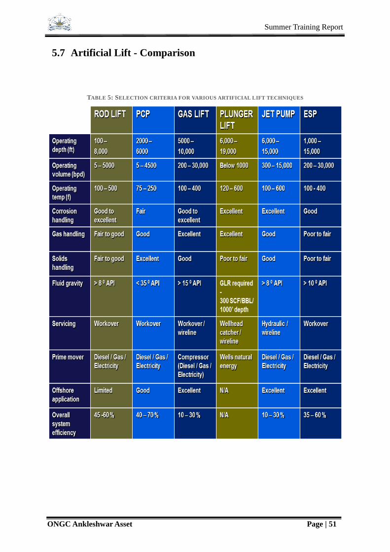
Summer Training Report
ONGC Ankleshwar Asset Page | 51
5.7 Artificial Lift - Comparison
TABLE 5: SELECTION CRITERIA FOR VARIOUS ARTIFICIAL LIFT TECHNIQUES