SUMMARY - Flexachem … · SUMMARY Section Description Page 1 INTRODUCTION TO PIPING IN PTFE PTFE...
74
Transcript of SUMMARY - Flexachem … · SUMMARY Section Description Page 1 INTRODUCTION TO PIPING IN PTFE PTFE...

Versioon 11/2006 2
SUMMARY
Section Description Page
1 INTRODUCTION TO PIPING IN PTFE
PTFE lined tube systems - Summary table 3 Features of pure PTFE 4 1. Thermal properties 4 2. Further physical properties 4 3. Mechanical properties 4 4. Electrical properties 5 5. Resistance to chemicals 5 6. Marking 5 7. Tolerances 5 8. Surface constitution 5 9. Quality inspections 5 10. Packing, Transport, Storing 5 11. Design Conditions 6 12. Assembly instructions 7 13. Safety 7 14. Lining Performance of PTFE 8
2 DIN SECTION
Flanged Pipes 9 45° Bends 10 90° Bends 11 Equal and Reducing Tee Pieces 12 Lateral Tees, with 45° branch 15 Equal and Reducing Crosses 16 Flanged Reducers (concentric and eccentric) 19 Reducing Flanges 21 Blank Flanges 24 Spacers 25
Instrument Tappings 26 Sight Glasses 27
Ball Check Valves 28 Y Strainers 29 Injection Pipes 30 Ptfe Injection Nozzles (without steel insert) 31 Dip Pipes 32 Double Wall Dip Pipes 33
Expansion Joints 34
Section Description Page
ANSI SECTION
Flanged Pipes 35 45° Bends 36 90° Bends 37 Equal and Reducing Tee Pieces 38 Lateral Tees, with 45° branch 41
Equal and Reducing Crosses 42 Flanged Reducers (concentric and eccentric) 45 Reducing Flanges 47 Blank Flanges 50 Spacers 51 Instrument Tappings 52 Sight Glasses 53 Ball Check Valves 54 Y Strainers 55 Injection Pipes 56 Ptfe Injection Nozzles (without steel insert) 57 Dip Pipes 58 Double Wall Dip Pipes 59 Expansion Joints 60
4 DIAGRAM PRESSURE-TEMPERATURE
For expansion joints with 2 convolutions 61 For expansion joints with 3 convolutions 62 For expansion joints with 4 convolutions 63 For expansion joints with 5 convolutions 64 For expansion joints with 6 convolutions 65 For expansion joints with 7 convolutions 66 For expansion joints with 8 convolutions 67
5 MANIFOLD SECTION 68
6 HEATING JACKETED MATERIAL 69
7 COLUMNS AND VESSELS 70
8 SPECIAL PIECES 72

Version 11/2006 3
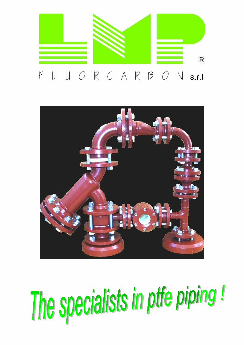
PTFE lined tube systems. PTFE exceptional resistance to chemical aggressions at temperatures between -200°C and +260°C accounts for its high corrosion strength, which makes it possible to use these piping systems in a wide range of applications. The processing techniques that we have expressly developed mainly consist of isostatic moulding and paste extrusion. The resulting end product has exclusive features as:
• High density and crystallinity which, coupled with a considerable wall thickness, make PTFE extremely vacuum-resistant, and at the same time protect it from gas and steam permeation.
• The homogeneous composition of the lining in critical spots, too, prevents weakening of the structure and thinning of the wall.
• A minimal initial subsidence, which then remains constant, minimizes deformation during the sintering process.
• The accurate processing keeps influence able properties such as resistance to strokes and bending, tensile strength and crystallinity at a constantly high standard.
• The strength of PTFE pipes, no matter the way they are processed, is the same radially and longitudinally, which makes the pipes particularly strong against vacuum and alternate pressures.
Summary table referred to DIN (ANSI) material. Nominal sizes DN 15 (½”) ÷ DN 300 (12”) (different sizes on request). Nominal pressure PN 10 – PN 16
c) T-shaped parts in compliance with DIN 2615 (ANSI: schedule 40)
Higher pressures are available on request. Pipes + shaped parts in compliance with DIN 2848 (ANSI B16.5).
d) Reducers in compliance with DIN 2616 : (ANSI: schedule 40)
Delivery terms in compliance with DIN 2874.
e) Sight glasses in compliance with DIN 28121
Types of Flanges:
DIN version:
Steel material: a) Shaped parts and tubes St 35 (1.0308) in Compliance with DIN 1629 Part 3.
Welding neck flanges for DN 15 up to DN 150 (ANSI: ASTM A 106 gr. B for pipes and ASTM A 234
in compliance with DIN 2633 (PN 16); for DN 200 up to DN 300 in compliance with DIN 2632 (PN 10). Lap joint flanges for DN 15 up to DN 150 in compliance with DIN 2577 (PN 16); for DN 200 up to DN 300 in compliance with DIN 2576 (PN 10). Ansi version: Flanges in compliance with ANSI 150 lbs.. Special flanges available on request
gr. WPB for fittings) b) Flanges: R-St 37-2 (1.10112) in compliance with DIN 17100 (ANSI: ASTM A105). c) the above mentioned classes of steel could
vary depending on availability on the market.
d) special steel with particular high-quality features is available on request.
Lining: Types of shaped parts: White “virgin” PTFE in compliance with DIN
28055 part 1 and 2 (ASTM D 4894 and 4895) a) 45° and 90° bends
For DN 15 up to DN 40: in compliance with DIN 2605 (5d) Other types: For DN 50 up to DN 300: in compliance with DIN 2605 (3d) Compound PTFE: (conductive versions –
special versions)
b) 45° and 90°bends Processing: For ½” up to 2”: Long Radius a) Pipes: DN 15 paste extrusion For 2½” up to 12”: Short Radius DN 20 ÷ 300 isostatic moulding b) Shaped parts: isostatic moulding

Version 11/2006 4
Features of pure PTFE (mean values)
1. Thermal properties Feature Value Unit Checking
method
Thermal application field -200 … + 260 °C Melting field 320 – 340 °C DTA Coefficient of linear expansion between 20°C and 100°C 16
. 10
-5 K
-1 DIN 52328
20°C and 200°C 19,5 . 10
-5 K
-1 (dilatometer)
20°C and 300°C 25 . 10
-5 K
-1
Specific heat
At 0°C 0,96 kJ/Kg K adiabatic At 50°C 1,03 kJ/Kg K calorimeter
Heat conductivity 0,25 – 0,50 W/m . K DIN 56612
2. Further physical properties Feature Value Unit Checking method
Water absorption None % DIN 53472 UV resistance and weatherability Very good ASTM E 42-57 T Flammability None DIN 53459
cm3 . cm Checked with Helium
Coefficient of permeability 2-8 . 10
-7 cm
. sec
. bar At +23°C – 50°C
Radiation resistance No damage
< 30 J/Kg
Destruction limit About 500 J/Kg
Brittleness 104
J/Kg
3. Mechanical properties Feature Value Unit Checking method
Density 2,15 – 2,20 g/cm3
DIN 53479 Tensile strength 20 – 40 N/mm
2 DIN 53455
Elongation at break 250…500 % DIN 53455 10% Expansion tension 11…12 N/mm
2 DIN 53455
Number of transverse contraction About 0,4 Modulus of E traction 750 N/mm
2 DIN 53457
Thrust modulus 750 N/mm2
DIN 53445
Resistance to pressure
Yielding limit 1% 10 N/mm2
DIN 53454
Yielding limit 10% 18 N/mm2
Resistivity to bending No breaking N/mm2
DIN 53452
Torsion rigidity 160 N/mm2
DIN 53447
Resistivity to strokes No breaking KJ/m2
DIN 53453
Resilience 16 KJ/m2
DIN 53453
Number of alternated bending >106
Load change DIN 53374
Shore hardness 55…59 Shore D DIN 53505
85…87 Shore C
Hardness according to Rockwell 80…95
Abrasion 470 mm3
DIN 53516
Version 11/2006 5
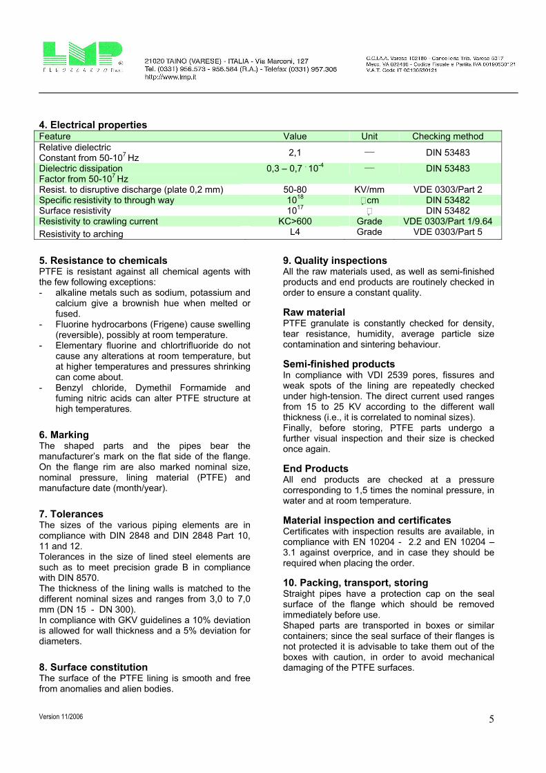
4. Electrical properties
Feature Value Unit Checking method
Relative dielectric Constant from 50-10
7 Hz
2,1 ___
DIN 53483
Dielectric dissipation Factor from 50-10
7 Hz
0,3 – 0,7 . 10
-4 ___ DIN 53483
Resist. to disruptive discharge (plate 0,2 mm) 50-80 KV/mm VDE 0303/Part 2 Specific resistivity to through way 10
18 # cm DIN 53482
Surface resistivity 1017
# DIN 53482 Resistivity to crawling current KC>600 Grade VDE 0303/Part 1/9.64
Resistivity to arching L4 Grade VDE 0303/Part 5
5. Resistance to chemicals PTFE is resistant against all chemical agents with the few following exceptions: - alkaline metals such as sodium, potassium and
calcium give a brownish hue when melted or fused.
- Fluorine hydrocarbons (Frigene) cause swelling (reversible), possibly at room temperature.
- Elementary fluorine and chlortrifluoride do not cause any alterations at room temperature, but at higher temperatures and pressures shrinking can come about.
- Benzyl chloride, Dymethil Formamide and fuming nitric acids can alter PTFE structure at high temperatures.
6. Marking The shaped parts and the pipes bear the manufacturer’s mark on the flat side of the flange. On the flange rim are also marked nominal size, nominal pressure, lining material (PTFE) and manufacture date (month/year).
7. Tolerances The sizes of the various piping elements are in compliance with DIN 2848 and DIN 2848 Part 10, 11 and 12. Tolerances in the size of lined steel elements are such as to meet precision grade B in compliance with DIN 8570. The thickness of the lining walls is matched to the different nominal sizes and ranges from 3,0 to 7,0 mm (DN 15 - DN 300). In compliance with GKV guidelines a 10% deviation is allowed for wall thickness and a 5% deviation for diameters.
8. Surface constitution The surface of the PTFE lining is smooth and free from anomalies and alien bodies.
9. Quality inspections All the raw materials used, as well as semi-finished products and end products are routinely checked in order to ensure a constant quality.
Raw material PTFE granulate is constantly checked for density, tear resistance, humidity, average particle size contamination and sintering behaviour.
Semi-finished products In compliance with VDI 2539 pores, fissures and weak spots of the lining are repeatedly checked under high-tension. The direct current used ranges from 15 to 25 KV according to the different wall thickness (i.e., it is correlated to nominal sizes). Finally, before storing, PTFE parts undergo a further visual inspection and their size is checked once again.
End Products All end products are checked at a pressure corresponding to 1,5 times the nominal pressure, in water and at room temperature.
Material inspection and certificates Certificates with inspection results are available, in compliance with EN 10204 - 2.2 and EN 10204 – 3.1 against overprice, and in case they should be required when placing the order.
10. Packing, transport, storing Straight pipes have a protection cap on the seal surface of the flange which should be removed immediately before use. Shaped parts are transported in boxes or similar containers; since the seal surface of their flanges is not protected it is advisable to take them out of the boxes with caution, in order to avoid mechanical damaging of the PTFE surfaces.

Version 11/2006 6
11: Design Conditions Hereunder we are showing the Design conditions for our material with “Standard Duty” ptfe lining:
“Standard Duty” Size 15
½”
20
¾”
25
1”
32
1¼”
40
1½”
50
2”
65
2½”
80
3”
100
4”
125
5”
150
6”
200
8”
250
10”
300
12”
Thickness of ptfe (mm) 3,0 3,0 3,0 3,0 3,0 3,0 3,5 4,0 4,5 4,5 5,0 6,0 7,0 7,0 Max design pressure (bar) 16 16 16 16 16 16 16 16 16 16 16 10 10 10 Min design temperature (°C) -10 -10 -10 -10 -10 -10 -10 -10 -10 -10 -10 -10 -10 -10 Max design temperature (°C) 200 200 200 200 200 200 200 200 200 200 200 200 200 200 Max desing vacuum at 200°C (mbar)
10 10 10 10 10 10 10 10 200 300 500 600 800 800
In case of more critical vacuum conditions, we developed a specific line of products called “Heavy Duty” with an increased thickness of ptfe lining and hereunder we are reporting its Design conditions: (values for sizes from DN 15 (½”) up to DN 80 (3”) included remain the same)
“Heavy Duty” Size 15
½”
20
¾”
25
1”
32
1¼”
40
1½”
50
2”
65
2½”
80
3”
100
4”
125
5”
150
6”
200
8”
250
10”
300
12”
Thickness of ptfe (mm) 3,0 3,0 3,0 3,0 3,0 3,0 3,5 4,0 7,0 7,0 8,0 9,5 11,0 11,0 Max design pressure (bar) 16 16 16 16 16 16 16 16 16 16 16 10 10 10 Min design temperature (°C) -10 -10 -10 -10 -10 -10 -10 -10 -10 -10 -10 -10 -10 -10 Max design temperature (°C) 200 200 200 200 200 200 200 200 200 200 200 200 200 200 Max desing vacuum at 200°C (mbar)
10 10 10 10 10 10 10 10 10 20 30 50 80 100
In the following table we are reporting the max vacuum resistance for “Standard Duty” and “Heavy Duty” items according to different temperatures:
“Standard Duty” “Heavy Duty” Size 15
½”
20
¾”
25
1”
32
1¼”
40
1½”
50
2”
65
2½”
80
3”
100
4”
125
5”
150
6”
200
8”
250
10”
300
12”
Max desing vacuum at 20°C (mbar) – S.D.
1 1 1 1 1 1 1 1 20 30 50 60 80 80
Max desing vacuum at 20°C (mbar) – H.D.
1 1 1 1 1 1 1 1 1 2 3 5 8 10
Max desing vacuum at 50°C (mbar) – S.D.
3 3 3 3 3 3 3 3 50 75 130 150 200 200
Max desing vacuum at 50°C (mbar) – H.D.
3 3 3 3 3 3 3 3 3 5 10 15 20 30
Max desing vacuum at 100°C (mbar) – S.D.
5 5 5 5 5 5 5 5 100 150 250 300 400 400
Max desing vacuum at 100°C (mbar) – H.D.
5 5 5 5 5 5 5 5 5 10 15 30 40 50
Max desing vacuum at 150°C (mbar) – S.D.
8 8 8 8 8 8 8 8 150 225 380 450 600 600
Max desing vacuum at 150°C (mbar) – H.D.
8 8 8 8 8 8 8 8 8 15 25 40 60 80
Max desing vacuum at 200°C (mbar) – S.D.
10 10 10 10 10 10 10 10 200 300 500 600 800 800
Max desing vacuum at 200°C (mbar) – H.D.
10 10 10 10 10 10 10 10 10 20 30 50 80 100

Version 11/2006 7
12. Assembly instructions for lined tubes and shaped parts The seal surface of the flanges is provided with a protection cap during transport and storing; the cap should be removed immediately before use. Do not remove the wooden protection caps until assembling and do not leave the pieces without protection caps under the sun. The lined parts of the tubes should not be welded or brazed in order to avoid damaging the lining.
Assembly of the single elements does not require further sealing, but a PTFE-lined sealing should be used when connecting the flange with materials such as glass or enamel in a not parallel way. Do not use sharp edges to mount the items: a cut on the ptfe flare does not permit to use the item any more.
Tighten always the bolting into a cross-section: an excessive traction during flange screwing may cause deformation on the seal surface.
Following twisting moments can be used as general criteria for assembly:
Specifications in Nm
DIN (ANSI) SIZE
PN 10 (for DN 200 and above)/PN 16 for others
(ANSI 150 lbs.) Number of screws and threads
Twisting moments (for
DIN and ANSI)
PN 25 (for DN 200 and above)/PN 40 for others.
(ANSI 300 lbs.) Number of screws and threads
Twisting moments (for DIN
and ANSI)
15 (½”) 4 x M12 (4 x ½”) 15 4 x M12 (4 x ½”) 17
20 (¾”) 4 x M12 (4 x ½”) 22 4 x M12 (4 x 5/8”) 25
25 (1”) 4 x M12 (4 x ½”) 22 4 x M12 (4 x 5/8”) 25
32 (1¼”) 4 x M16 (4 x ½”) 25 4 x M16 (4 x 5/8”) 30
40 (1½”) 4 x M16 (4 x ½”) 25 4 x M16 (4 x ¾”) 30
50 (2”) 4 x M16 (4 x 5/8”) 35 4 x M16 (8 x 5/8”) 40
65 (2½”) 4 x M16 (4 x 5/8”) 45 8 x M16 (8 x ¾”) 50
80 (3”) 8 x M16 (4 x 5/8”) 45 8 x M16 (8 x ¾”) 50
100 (4”) 8 x M16 (8 x 5/8”) 50 8 x M20 (8 x ¾”) 55
125 (5”) 8 x M16 (8 x ¾”) 60 8 x M24 (8 x ¾”) 80
150 (6”) 8 x M20 (8 x ¾”) 70 8 x M24 (12 x ¾”) 95
200 (8”) 8 x M20 (8 x ¾”) 100 12 x M24 (12 x 7/8”) 120
250 (10”) 12 x M20 (12 x 7/8”) 100 12 x M27 (16 x 1”) 120
300 (12”) 12 x M20 (12 x 7/8”) 120 16 x M27 (16 x 1 1/8”) 140
These specifications are referred to maximal temperature and screws with lubrificated threads easy to insert. About 24 hours after the screwing is operative, once the final temperature has been reached, the screwing should be checked in relation to the twisting moments. At room temperature the values concerning the twisting moments can be exceeded up to 50%. The whole piping is provided with holes: it is important not to obstruct them when insulation or anti-corrosion means are taken. When the temperature exceeds 50°C the piping should not be dismantled in order to avoid damaging the seal surfaces. In case of leakages at the points where the flanges meet, the screws should not be tightened: on the contrary the connection should be loosened in order to allow inspection for alien bodies or unevenness.
13. Safety. The Producer (L.M.P. Fluorcarbon s.r.l.) is not supplying safety valves or alternative systems to avoid any excessive pressure inside the delivered materials, which could cause serious damages to people and/or plants and/or part of the same: the operation for
granting a safety conditions of the items will be on User’s account. Moreover, the items supplied by the Producer (L.M.P. Fluorcarbon s.r.l.) are studied to be used with presence of high temperature (up to 200°C), even if they are not protected outside because of the very particular nature of the material and of the protective barriers available on the market, which are suitable to be used with pipes and fittings in steel with inside ptfe lining. Finally, the steel frames with ptfe lining inside are studied for the passage of dangerous, corrosive and toxic fluid, in any case, substances that in case they come out from the piping line, could cause serous damages to people, animals, things and environment: the final User must utilize all the available and possible means in order to avoid any accident, paying particular attention to the protection, maintenance and right use of the delivered items. The Producer (L.M.P. Fluorcarbon S.r.l.) cannot be considered responsible for any damages to people, animals, things and environment, caused by the User with an improper use, or without the respect of the working conditions communicated, or even for lack of application of the Law Disposals and of any applicable regulation.
Version 11/2006 8
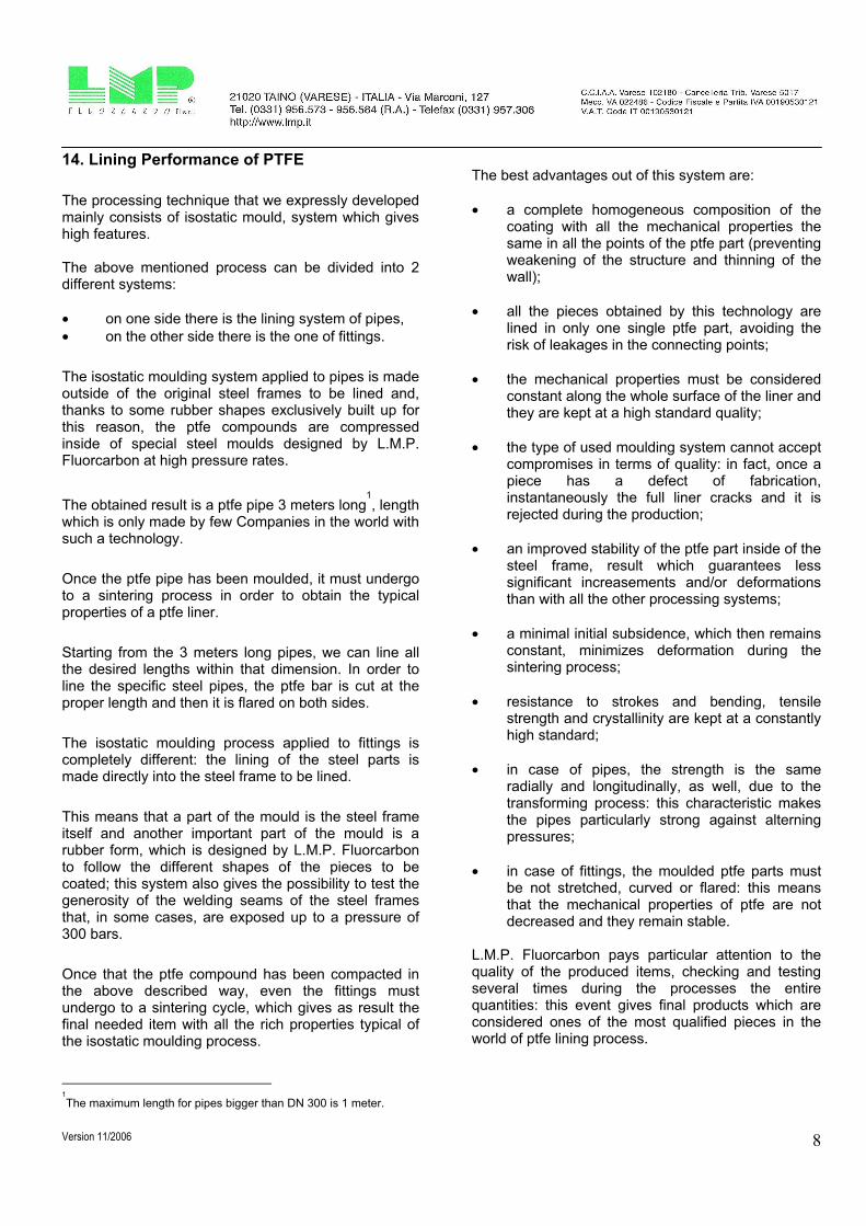
14. Lining Performance of PTFE
The processing technique that we expressly developed mainly consists of isostatic mould, system which gives high features. The above mentioned process can be divided into 2 different systems:
• on one side there is the lining system of pipes,
• on the other side there is the one of fittings.
The isostatic moulding system applied to pipes is made outside of the original steel frames to be lined and, thanks to some rubber shapes exclusively built up for this reason, the ptfe compounds are compressed inside of special steel moulds designed by L.M.P. Fluorcarbon at high pressure rates.
The obtained result is a ptfe pipe 3 meters long
1
, length which is only made by few Companies in the world with such a technology.
Once the ptfe pipe has been moulded, it must undergo to a sintering process in order to obtain the typical properties of a ptfe liner.
Starting from the 3 meters long pipes, we can line all the desired lengths within that dimension. In order to line the specific steel pipes, the ptfe bar is cut at the proper length and then it is flared on both sides.
The isostatic moulding process applied to fittings is completely different: the lining of the steel parts is made directly into the steel frame to be lined.
This means that a part of the mould is the steel frame itself and another important part of the mould is a rubber form, which is designed by L.M.P. Fluorcarbon to follow the different shapes of the pieces to be coated; this system also gives the possibility to test the generosity of the welding seams of the steel frames that, in some cases, are exposed up to a pressure of 300 bars.
Once that the ptfe compound has been compacted in the above described way, even the fittings must undergo to a sintering cycle, which gives as result the final needed item with all the rich properties typical of the isostatic moulding process.
1
The maximum length for pipes bigger than DN 300 is 1 meter.
The best advantages out of this system are:
• a complete homogeneous composition of the coating with all the mechanical properties the same in all the points of the ptfe part (preventing weakening of the structure and thinning of the wall);
• all the pieces obtained by this technology are lined in only one single ptfe part, avoiding the risk of leakages in the connecting points;
• the mechanical properties must be considered constant along the whole surface of the liner and they are kept at a high standard quality;
• the type of used moulding system cannot accept compromises in terms of quality: in fact, once a piece has a defect of fabrication, instantaneously the full liner cracks and it is rejected during the production;
• an improved stability of the ptfe part inside of the steel frame, result which guarantees less significant increasements and/or deformations than with all the other processing systems;
• a minimal initial subsidence, which then remains constant, minimizes deformation during the sintering process;
• resistance to strokes and bending, tensile strength and crystallinity are kept at a constantly high standard;
• in case of pipes, the strength is the same radially and longitudinally, as well, due to the transforming process: this characteristic makes the pipes particularly strong against alterning pressures;
• in case of fittings, the moulded ptfe parts must be not stretched, curved or flared: this means that the mechanical properties of ptfe are not decreased and they remain stable.
L.M.P. Fluorcarbon pays particular attention to the quality of the produced items, checking and testing several times during the processes the entire quantities: this event gives final products which are considered ones of the most qualified pieces in the world of ptfe lining process.

Version 11/2006
9
FLANGED PIPES (DIN 2848 part 12).
Material specification: Tube: St 35 in compliance with DIN 1629 Part 3 (1.0308)
Flanges: R-St 37-2 in compliance with DIN 17100 (1.0112)
Lining: Pure PTFE in compliance with ASTM D 1457-78 type IV e V
Delivery terms: in compliance with DIN 2874
Dimensions expressed in mm.
L DN 15 ÷ 300: 3.000m ax.
d d1
d4
k
h h
d2
1 2
D
s f
s
DN d1 sf d s n x d2 d4 k D h1 h2
15 24,0 3,0 12 3 4 x 14 45 65 95 16,5 26,5
20 33,7 2,6 22 3 4 x 14 58 75 105 19 29
25 33,7 2,6 22 3 4 x 14 68 85 115 19 31
32 44,0 3,0 31 3 4 x 18 78 100 140 19 31
40 48,3 2,6 37 3 4 x 18 88 110 150 19 31
50 60,3 2,9 48 3 4 x 18 102 125 165 21 33
65 76,1 2,9 63 3,5 4 x 18 122 145 185 21,5 33,5
80 88,9 3,2 75 4 8 x 18 138 160 200 23,5 37,5
100 114,3 3,6 99 4,5 8 x 18 158 180 220 24 38
125 139,7 4,0 122 4,5 8 x 18 188 210 250 26,5 40,5
150 168,3 4,5 149 5 8 x 22* 212 240 285 27 41
200 219,1 6,3 194 6 8 x 22* 268 295 340 30 46
250 273,0 6,3 248 7 12 x 22* 320 350 395 32 50
300 323,9 7,1 297 7 12 x 22* 370 400 445 32 54
* for flanges according to DIN 2673 it is 8 x 23 or 12 x 23.
On request it is available “Heavy Duty” material suitable for vacuum. Vent Holes according to Producer’s option.
Weights in Kgs.
Size 15 20 25 32 40 50 65 80 100 125 150 200 250 300
1 meter pipe 1,4 1,8 2,5 3,2 3,7 5,1 6,8 8,6 12,6 18,0 23,4 39,1 51,7 67,7
loose+fixed flange 1,5 2,0 2,6 3,7 4,2 5,5 6,7 8,5 10,2 13,6 16,5 23,5 32,7 44,0

Version 11/2006
10
FLANGED 45° BENDS according to DIN 2848
Material specification: Steel frame: St. 35 in compliance with DIN 1629 Part 3 (1.0308)
Flanges: R-St 37-2 in compliance with DIN 17100 (1.10112)
Lining: Pure Ptfe in compliance with ASTM-D 1457-78 Type IV - V
Delivery time: in compliance with DIN 2874
Sizes are expressed in mm.
D
k
d
l /l
3
4
l /l
3
4
r
4
s
DN s Type of bend r l3 l4 d4 k D Weight kg.
15 3 5d 42,5 45 45 65 95 1,9
20 3 5d 72,5 65 58 75 105 2,2
25 3 5d 72,5 70 68 85 115 2,6
32 3 5d 92,5 80 78 100 140 3,8
40 3 5d 107,5 90 88 110 150 4,2
50 3 3d 76 80 102 125 165 5,5
65 3,5 3d 95 85 122 145 185 7,2
80 4 3d 114,5 100 138 160 200 10,0
100 4,5 3d 152,5 115 158 180 220 12,0
125 4,5 3d 190,5 135 188 210 250 17,1
150 5 3d 228,5 150 212 240 285 22,3
200 6 3d 305 190 268 295 340 33,0
250 7 3d 381 225 320 350 395 54,0
300 7 3d 457 260 370 400 445 76,0
On request it is available “Heavy Duty” material suitable for vacuum.
On request we can supply bends with different angles
Vent Holes according to producer’s discretion.

Version 11/2006
11
FLANGED 90° BENDS (DIN 2848)
Material specification: Steel Frame: St 35 in compliance with DIN 1629 Part 3 (1.0308)
Flanges: R-St 37-2 in compliance with DIN 17100 (1.0112)
Lining: Pure PTFE in compliance with ASTM D 1457-78 type IV e V
Delivery terms: in compliance with DIN 2874
Sizes are expressed in mm.
l /l 1 2
l /l
21
rd
k D
s
4
DN s Type of bend r l1 l2 d4 k D Weight kg.
15 3 5d 42,5 80 45 65 95 2,0
20 3 5d 72,5 95 58 75 105 2,3
25 3 5d 72,5 110 68 85 115 2,9
32 3 5d 92,5 130 78 100 140 4,0
40 3 5d 107,5 150 88 110 150 4,5
50 3 3d 76 120 102 125 165 6,0
65 3,5 3d 95 140 122 145 185 7,9
80 4 3d 114,5 165 138 160 200 10,4
100 4,5 3d 152,5 205 158 180 220 12,6
125 4,5 3d 190,5 245 188 210 250 19,0
150 5 3d 228,5 285 212 240 285 26,0
200 6 3d 305 365 268 295 340 48,1
250 7 3d 381 450 320 350 395 76,2
300 7 3d 457 525 370 400 445 110,0
On request, “Heavy Duty” pieces are available for vacuum conditions.
Steel frames are according to schedule 40.
On request, bends with different angles are available.
Vent holes at Manufacturer’s discretion.

Version 11/2006 12
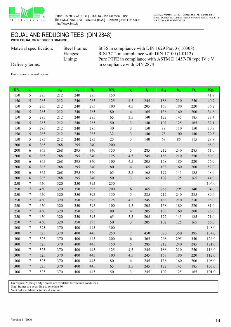
EQUAL AND REDUCING TEES (DIN 2848) WITH EQUAL OR REDUCED BRANCH
Material specification: Steel Frame: St 35 in compliance with DIN 1629 Part 3 (1.0308)
Flanges: R-St 37-2 in compliance with DIN 17100 (1.0112)
Lining: Pure PTFE in compliance with ASTM D 1457-78 type IV e V
Delivery terms: in compliance with DIN 2874
Dimensions expressed in mm.
dkD
D
k
d
l
l l
DN
DN
1
2
42
2
2
1 1
41
11
2
s1
s2
DN1 s1 l1 d41 k1 D1 DN2 s2 l2 d42 k2 D2 Kg.
15 3 80 45 65 95 15 2,4
20 3 95 58 75 105 20 3,3
20 3 95 58 75 105 15 3 80 45 65 95 2,7
25 3 110 68 85 115 25 4,4
25 3 110 68 85 115 20 3 95 58 75 105 4,0
25 3 110 68 85 115 15 3 80 45 65 95 3,6
32 3 130 78 100 140 32 6,4
32 3 130 78 100 140 25 3 110 68 85 115 6,1
32 3 130 78 100 140 20 3 95 58 75 105 5,8
32 3 130 78 100 140 15 3 80 45 65 95 5,5
40 3 150 88 110 150 40 7,8
40 3 150 88 110 150 32 3 130 78 100 140 7,5
40 3 150 88 110 150 25 3 110 68 85 115 7,1
40 3 150 88 110 150 20 3 95 58 75 105 6,8
40 3 150 88 110 150 15 3 80 45 65 95 6,5

Version 11/2006 13
EQUAL AND REDUCING TEES (DIN 2848) WITH EQUAL OR REDUCED BRANCH
Material specification: Steel Frame: St 35 in compliance with DIN 1629 Part 3 (1.0308)
Flanges: R-St 37-2 in compliance with DIN 17100 (1.0112)
Lining: Pure PTFE in compliance with ASTM D 1457-78 type IV e V
Delivery terms: in compliance with DIN 2874
Dimensions expressed in mm.
DN1 s1 l1 d41 k1 D1 DN2 s2 l2 d42 k2 D2 Kg.
50 3 120 102 125 165 50 9,6
50 3 120 102 125 165 40 3 150 88 110 150 8,4
50 3 120 102 125 165 32 3 130 78 100 140 7,9
50 3 120 102 125 165 25 3 110 68 85 115 7,6
50 3 120 102 125 165 20 3 95 58 75 105 7,3
50 3 120 102 125 165 15 3 80 45 65 95 7,0
65 3,5 140 122 145 185 65 11,7
65 3,5 140 122 145 185 50 3 120 102 125 165 11,0
65 3,5 140 122 145 185 40 3 150 88 110 150 10,2
65 3,5 140 122 145 185 32 3 130 78 100 140 9,6
65 3,5 140 122 145 185 25 3 110 68 85 115 9,0
65 3,5 140 122 145 185 20 3 95 58 75 105 8,5
65 3,5 140 122 145 185 15 3 80 45 65 95 8,3
80 4 165 138 160 200 80 16,9
80 4 165 138 160 200 65 3,5 140 122 145 185 15,0
80 4 165 138 160 200 50 3 120 102 125 165 13,8
80 4 165 138 160 200 40 3 150 88 110 150 13,0
80 4 165 138 160 200 32 3 130 78 100 140 12,5
80 4 165 138 160 200 25 3 110 68 85 115 12,1
80 4 165 138 160 200 20 3 95 58 75 105 11,6
80 4 165 138 160 200 15 3 95 45 65 95 11,0
100 4,5 205 158 180 220 100 20,7
100 4,5 205 158 180 220 80 4 165 138 160 200 19,2
100 4,5 205 158 180 220 65 3,5 140 122 145 185 18,1
100 4,5 205 158 180 220 50 3 120 102 125 165 17,1
100 4,5 205 158 180 220 40 3 150 88 110 150 16,3
100 4,5 205 158 180 220 32 3 130 78 100 140 15,4
100 4,5 205 158 180 220 25 3 110 68 85 115 15,0
100 4,5 205 158 180 220 20 3 110 58 75 105 14,4
100 4,5 205 158 180 220 15 3 110 45 65 95 14,0
125 4,5 245 188 210 250 125 31,3
125 4,5 245 188 210 250 100 4,5 205 158 180 220 30,0
125 4,5 245 188 210 250 80 4 165 138 160 200 28,9
125 4,5 245 188 210 250 65 3,5 140 122 145 185 28,0
125 4,5 245 188 210 250 50 3 120 102 125 165 27,2
125 4,5 245 188 210 250 40 3 150 88 110 150 26,4
125 4,5 245 188 210 250 32 3 130 78 100 140 25,7
125 4,5 245 188 210 250 25 3 120 68 85 115 25,0
Version 11/2006 14
EQUAL AND REDUCING TEES (DIN 2848) WITH EQUAL OR REDUCED BRANCH
Material specification: Steel Frame: St 35 in compliance with DIN 1629 Part 3 (1.0308)
Flanges: R-St 37-2 in compliance with DIN 17100 (1.0112)
Lining: Pure PTFE in compliance with ASTM D 1457-78 type IV e V
Delivery terms: in compliance with DIN 2874
Dimensions expressed in mm.
DN1 s1 l1 d41 k1 D1 DN2 s2 l2 d42 k2 D2 Kg.
150 5 285 212 240 285 150 41,8
150 5 285 212 240 285 125 4,5 245 188 210 250 40,7
150 5 285 212 240 285 100 4,5 205 158 180 220 36,2
150 5 285 212 240 285 80 4 165 138 160 200 34,8
150 5 285 212 240 285 65 3,5 140 122 145 185 33,4
150 5 285 212 240 285 50 3 140 102 125 165 32,1
150 5 285 212 240 285 40 3 150 88 110 150 30,9
150 5 285 212 240 285 32 3 140 78 100 140 29,8
150 5 285 212 240 285 25 3 140 68 85 115 28,8
200 6 365 268 295 340 200 68,0
200 6 365 268 295 340 150 5 285 212 240 285 61,0
200 6 365 268 295 340 125 4,5 245 188 210 250 60,0
200 6 365 268 295 340 100 4,5 205 158 180 220 56,0
200 6 365 268 295 340 80 4 165 138 160 200 52,0
200 6 365 268 295 340 65 3,5 165 122 145 185 48,0
200 6 365 268 295 340 50 3 165 102 125 165 44,0
250 7 450 320 350 395 250 104,0
250 7 450 320 350 395 200 6 365 268 295 340 94,0
250 7 450 320 350 395 150 5 285 212 240 285 89,0
250 7 450 320 350 395 125 4,5 245 188 210 250 85,0
250 7 450 320 350 395 100 4,5 205 158 180 220 81,0
250 7 450 320 350 395 80 4 205 138 160 200 76,0
250 7 450 320 350 395 65 3,5 205 122 145 185 71,0
250 7 450 320 350 395 50 3 205 102 125 165 66,0
300 7 525 370 400 445 300 148,0
300 7 525 370 400 445 250 7 450 320 350 395 134,0
300 7 525 370 400 445 200 6 365 268 295 340 126,0
300 7 525 370 400 445 150 5 285 212 240 285 121,0
300 7 525 370 400 445 125 4,5 245 188 210 250 116,0
300 7 525 370 400 445 100 4,5 245 158 180 220 112,0
300 7 525 370 400 445 80 4 245 138 160 200 108,0
300 7 525 370 400 445 65 3,5 245 122 145 185 105,0
300 7 525 370 400 445 50 3 245 102 125 165 101,0
On request, “Heavy Duty” pieces are available for vacuum conditions.
Steel frames are according to schedule 40.
Vent holes at Manufacturer’s discretion.

Version 11/2006 15
LATERAL TEES, with 45° branch
Material specification: Steel frames: St 35 in compliance with DIN 1629 Part 3 (1.0308)
Flanges: R-St 37-2 in compliance with DIN 17100 (1.0112)
Lining: Pure PTFE in compliance with ASTM D 1457-78 type IV - V
Delivery terms: in compliance with DIN 2874
Sizes are expressed in mm.
l l
l
k d D
2 1
1
4
45°
s
DN s l1 l2 d4 k D Weight kg.
25 3 180 40 68 85 115 4,2
32 3 210 45 78 100 140 6,1
40 3 220 50 88 110 150 7,5
50 3 240 55 102 125 165 9,3
65 3,5 260 60 122 145 185 11,2
80 4 290 70 138 160 200 16,3
100 4,5 320 80 158 180 220 19,9
125 4,5 350 90 188 210 250 30,1
150 5 380 100 212 240 285 41,0
200 6 455 120 268 295 340 68,0
Steel frames are according to schedule 40.
On request, “Heavy Duty” pieces are available for vacuum condition.
Reduced lateral tees and/or lateral tees with different angles can be taken into account.
Vent holes at Manufacturer’s discretion.

Version 11/2006 16
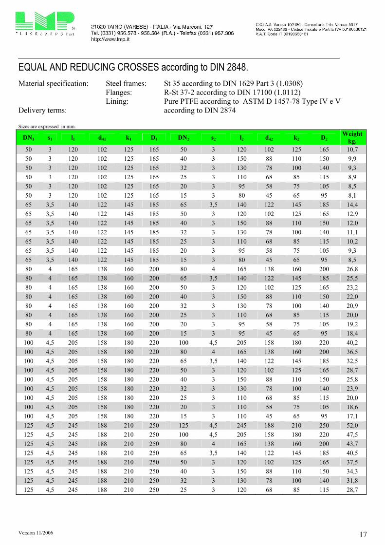
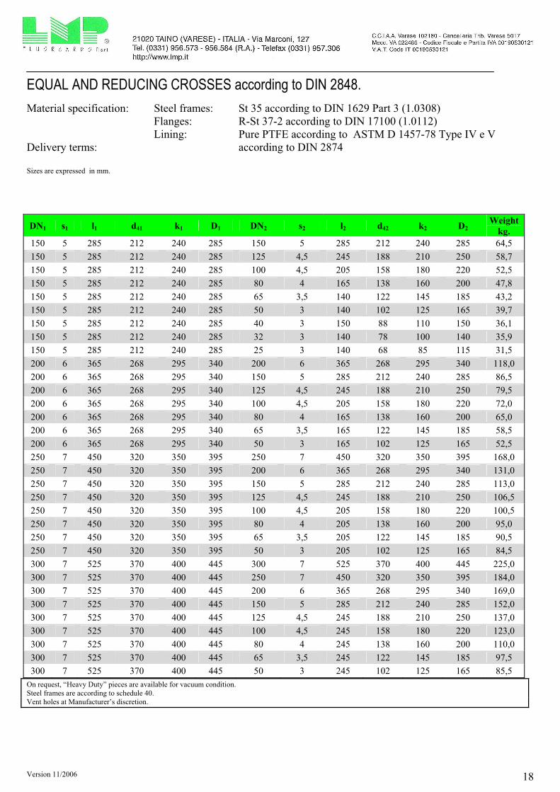
EQUAL AND REDUCING CROSSES according to DIN 2848.
Material specification: Steel frames: St 35 according to DIN 1629 Part 3 (1.0308)
Flanges: R-St 37-2 according to DIN 17100 (1.0112)
Lining: Pure PTFE according to ASTM D 1457-78 Type IV e V
Delivery terms: according to DIN 2874
Sizes are expressed in mm.
d 42
k
D
2
2
D k d 1 1 4
1
l l 1 1
l 2l 2
DN1
DN2
s1
s2
DN1 s1 l1 d41 k1 D1 DN2 s2 l2 d42 k2 D2 Weight
kg. 15 3 80 45 65 95 15 3 80 45 65 95 3,0
20 3 95 58 75 105 20 3 95 58 75 105 4,1
20 3 95 58 75 105 15 3 80 45 65 95 3,2
25 3 110 68 85 115 25 3 110 68 85 115 4,8
25 3 110 68 85 115 20 3 95 58 75 105 4,5
25 3 110 68 85 115 15 3 80 45 65 95 4,2
32 3 130 78 100 140 32 3 130 78 100 140 6,1
32 3 130 78 100 140 25 3 110 68 85 115 5,3
32 3 130 78 100 140 20 3 95 58 75 105 4,5
32 3 130 78 100 140 15 3 80 45 65 95 3,7
40 3 150 88 110 150 40 3 150 88 110 150 8,2
40 3 150 88 110 150 32 3 130 78 100 140 8,0
40 3 150 88 110 150 25 3 110 68 85 115 7,8
40 3 150 88 110 150 20 3 95 58 75 105 7,5
40 3 150 88 110 150 15 3 80 45 65 95 7,1
Version 11/2006 17
EQUAL AND REDUCING CROSSES according to DIN 2848.
Material specification: Steel frames: St 35 according to DIN 1629 Part 3 (1.0308)
Flanges: R-St 37-2 according to DIN 17100 (1.0112)
Lining: Pure PTFE according to ASTM D 1457-78 Type IV e V
Delivery terms: according to DIN 2874
Sizes are expressed in mm.
DN1 s1 l1 d41 k1 D1 DN2 s2 l2 d42 k2 D2 Weight
kg. 50 3 120 102 125 165 50 3 120 102 125 165 10,7
50 3 120 102 125 165 40 3 150 88 110 150 9,9
50 3 120 102 125 165 32 3 130 78 100 140 9,3
50 3 120 102 125 165 25 3 110 68 85 115 8,9
50 3 120 102 125 165 20 3 95 58 75 105 8,5
50 3 120 102 125 165 15 3 80 45 65 95 8,1
65 3,5 140 122 145 185 65 3,5 140 122 145 185 14,4
65 3,5 140 122 145 185 50 3 120 102 125 165 12,9
65 3,5 140 122 145 185 40 3 150 88 110 150 12,0
65 3,5 140 122 145 185 32 3 130 78 100 140 11,1
65 3,5 140 122 145 185 25 3 110 68 85 115 10,2
65 3,5 140 122 145 185 20 3 95 58 75 105 9,3
65 3,5 140 122 145 185 15 3 80 45 65 95 8,5
80 4 165 138 160 200 80 4 165 138 160 200 26,8
80 4 165 138 160 200 65 3,5 140 122 145 185 25,5
80 4 165 138 160 200 50 3 120 102 125 165 23,2
80 4 165 138 160 200 40 3 150 88 110 150 22,0
80 4 165 138 160 200 32 3 130 78 100 140 20,9
80 4 165 138 160 200 25 3 110 68 85 115 20,0
80 4 165 138 160 200 20 3 95 58 75 105 19,2
80 4 165 138 160 200 15 3 95 45 65 95 18,4
100 4,5 205 158 180 220 100 4,5 205 158 180 220 40,2
100 4,5 205 158 180 220 80 4 165 138 160 200 36,5
100 4,5 205 158 180 220 65 3,5 140 122 145 185 32,5
100 4,5 205 158 180 220 50 3 120 102 125 165 28,7
100 4,5 205 158 180 220 40 3 150 88 110 150 25,8
100 4,5 205 158 180 220 32 3 130 78 100 140 23,9
100 4,5 205 158 180 220 25 3 110 68 85 115 20,0
100 4,5 205 158 180 220 20 3 110 58 75 105 18,6
100 4,5 205 158 180 220 15 3 110 45 65 95 17,1
125 4,5 245 188 210 250 125 4,5 245 188 210 250 52,0
125 4,5 245 188 210 250 100 4,5 205 158 180 220 47,5
125 4,5 245 188 210 250 80 4 165 138 160 200 43,7
125 4,5 245 188 210 250 65 3,5 140 122 145 185 40,5
125 4,5 245 188 210 250 50 3 120 102 125 165 37,5
125 4,5 245 188 210 250 40 3 150 88 110 150 34,3
125 4,5 245 188 210 250 32 3 130 78 100 140 31,8
125 4,5 245 188 210 250 25 3 120 68 85 115 28,7
Version 11/2006 18
EQUAL AND REDUCING CROSSES according to DIN 2848.
Material specification: Steel frames: St 35 according to DIN 1629 Part 3 (1.0308)
Flanges: R-St 37-2 according to DIN 17100 (1.0112)
Lining: Pure PTFE according to ASTM D 1457-78 Type IV e V
Delivery terms: according to DIN 2874
Sizes are expressed in mm.
DN1 s1 l1 d41 k1 D1 DN2 s2 l2 d42 k2 D2 Weight
kg.
150 5 285 212 240 285 150 5 285 212 240 285 64,5
150 5 285 212 240 285 125 4,5 245 188 210 250 58,7
150 5 285 212 240 285 100 4,5 205 158 180 220 52,5
150 5 285 212 240 285 80 4 165 138 160 200 47,8
150 5 285 212 240 285 65 3,5 140 122 145 185 43,2
150 5 285 212 240 285 50 3 140 102 125 165 39,7
150 5 285 212 240 285 40 3 150 88 110 150 36,1
150 5 285 212 240 285 32 3 140 78 100 140 35,9
150 5 285 212 240 285 25 3 140 68 85 115 31,5
200 6 365 268 295 340 200 6 365 268 295 340 118,0
200 6 365 268 295 340 150 5 285 212 240 285 86,5
200 6 365 268 295 340 125 4,5 245 188 210 250 79,5
200 6 365 268 295 340 100 4,5 205 158 180 220 72,0
200 6 365 268 295 340 80 4 165 138 160 200 65,0
200 6 365 268 295 340 65 3,5 165 122 145 185 58,5
200 6 365 268 295 340 50 3 165 102 125 165 52,5
250 7 450 320 350 395 250 7 450 320 350 395 168,0
250 7 450 320 350 395 200 6 365 268 295 340 131,0
250 7 450 320 350 395 150 5 285 212 240 285 113,0
250 7 450 320 350 395 125 4,5 245 188 210 250 106,5
250 7 450 320 350 395 100 4,5 205 158 180 220 100,5
250 7 450 320 350 395 80 4 205 138 160 200 95,0
250 7 450 320 350 395 65 3,5 205 122 145 185 90,5
250 7 450 320 350 395 50 3 205 102 125 165 84,5
300 7 525 370 400 445 300 7 525 370 400 445 225,0
300 7 525 370 400 445 250 7 450 320 350 395 184,0
300 7 525 370 400 445 200 6 365 268 295 340 169,0
300 7 525 370 400 445 150 5 285 212 240 285 152,0
300 7 525 370 400 445 125 4,5 245 188 210 250 137,0
300 7 525 370 400 445 100 4,5 245 158 180 220 123,0
300 7 525 370 400 445 80 4 245 138 160 200 110,0
300 7 525 370 400 445 65 3,5 245 122 145 185 97,5
300 7 525 370 400 445 50 3 245 102 125 165 85,5
On request, “Heavy Duty” pieces are available for vacuum condition.
Steel frames are according to schedule 40.
Vent holes at Manufacturer’s discretion.

Version 11/2006 19
FLANGED REDUCERS (DIN 2848) CONCENTRIC / ECCENTRIC
Material specification: Steel frame: St 35 in compliance with DIN 1629 Part 3 (1.0308)
Flanges: R-St 37-2 in compliance with DIN 17100 (1.0112)
Lining: Pure PTFE in compliance with ASTM D 1457-78 type IV e V
Delivery conditions: in compliance with DIN 2874
Dimensions expressed in mm.
l l3 3
kD
11
D k
1 1
k D22
Dk2 2
DN1
DN2
DN1
DN2
e
s
s
1
2
s1
2s
DN1 s1 DN2 s2 e l3 k1 D1 k2 D2 Weight
kg. 20 3 15 3 3 125 75 105 65 95 2,1
25 3 20 3 3 125 85 115 75 105 2,3
25 3 15 3 3 125 85 115 65 95 2,2
32 3 25 3 4 130 100 140 85 115 3,1
32 3 20 3 4 130 100 140 75 105 2,9
32 3 15 3 4 130 100 140 65 95 2,5
40 3 32 3 3 150 110 150 100 140 4,3
40 3 25 3 7 145 110 150 85 115 3,4
40 3 20 3 7 145 110 150 75 105 2,5
40 3 15 3 7 145 110 150 65 95 1,8
50 3 40 3 6 165 125 165 110 150 5,3
50 3 32 3 9 165 125 165 100 140 4,8
50 3 25 3 13 160 125 165 85 115 4,3
50 3 20 3 13 160 125 165 75 105 3,8
50 3 15 3 13 160 125 165 65 95 3,0

Version 11/2006 20
FLANGED REDUCERS (DIN 2848) CONCENTRIC / ECCENTRIC
Material specification: Steel frame: St 35 in compliance with DIN 1629 Part 3 (1.0308)
Flanges: R-St 37-2 in compliance with DIN 17100 (1.0112)
Lining: Pure PTFE in compliance with ASTM D 1457-78 type IV e V
Delivery conditions: in compliance with DIN 2874 Dimensions expressed in mm.
DN1 s1 DN2 s2 e l3 k1 D1 k2 D2 Weight
kg.
65 3,5 50 3 8 185 145 185 125 165 6,5
65 3,5 40 3 14 180 145 185 110 150 5,9
65 3,5 32 3 17 180 145 185 100 140 5,7
65 3,5 25 3 21 180 145 185 85 115 5,5
65 3,5 20 3 21 180 145 185 75 105 5,2
65 3,5 15 3 21 180 145 185 65 95 4,9
80 4 65 3,5 6 190 160 200 145 185 8,8
80 4 50 3 14 190 160 200 125 165 8,2
80 4 40 3 20 185 160 200 110 150 7,1
80 4 32 3 23 185 160 200 100 140 6,0
80 4 25 3 28 185 160 200 85 115 5,8
80 4 20 3 28 185 160 200 75 105 5
80 4 15 3 28 185 160 200 65 95 4,1
100 4,5 80 4 13 205 180 220 160 200 10,3
100 4,5 65 3,5 19 200 180 220 145 185 9,8
100 4,5 50 3 27 200 180 220 125 165 9,3
100 4,5 40 3 33 200 180 220 110 150 8,8
100 4,5 32 3 36 200 180 220 100 140 8,3
100 4,5 25 3 40 200 180 220 85 115 8,0
100 4,5 20 3 40 200 180 220 75 105 7,6
100 4,5 15 3 40 200 180 220 65 95 7,1
125 4,5 100 4,5 13 235 210 250 180 220 13,9
125 4,5 80 4 25 235 210 250 160 200 12,8
125 4,5 65 3,5 32 230 210 250 145 185 12,4
125 4,5 50 3 40 230 210 250 125 165 12,0
150 5 125 4,5 14 250 240 285 210 250 18,1
150 5 100 4,5 27 250 240 285 180 220 16,5
150 5 80 4 40 250 240 285 160 200 15,9
150 5 65 3,5 46 250 240 285 145 185 15,0
150 5 50 3 54 250 240 285 125 165 14,2
200 6 150 5 25 270 295 340 240 285 26,3
200 6 125 4,5 40 270 295 340 210 250 25,8
200 6 100 4,5 52 270 295 340 180 220 23,6
250 7 200 6 27 310 350 395 295 340 38,2
250 7 150 5 52 305 350 395 240 285 34,6
250 7 125 4,5 67 305 350 395 210 250 34,1
250 7 100 4,5 79 305 350 395 180 220 33,7
300 7 250 7 25 340 400 445 350 395 48,8
300 7 200 6 52 335 400 445 295 340 45,3
300 7 150 5 78 330 400 445 240 285 41,8
On request, “Heavy Duty” pieces are available for vacuum conditions.
Steel frames are according to schedule 40. Vent holes at Manufacturer’s discretion.

Version 11/2006 21
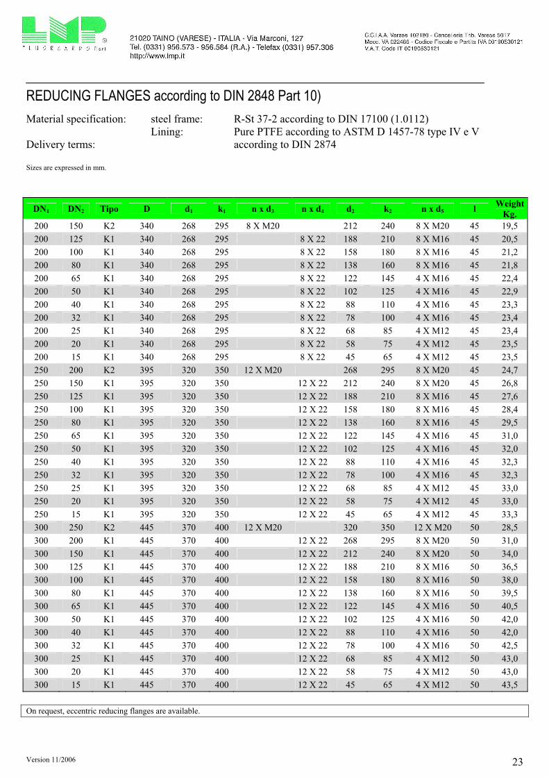
REDUCING FLANGES according to DIN 2848 Part 10)
Material specification: steel frame: R-St 37-2 according to DIN 17100 (1.0112)
Lining: Pure PTFE according to ASTM D 1457-78 type IV e V
Delivery terms: according to DIN 2874
Sizes are expressed in mm.
DN1
2
DN1
DN2
DN1
DN2
d5
>
d>
5
d>
5
d4
L L L
d
d
k
d
k
D
DN
2
2
1
1
5d
5
2
2
d
k
D
k
d
1
1
3d
d5
2
2
d
k
D
k
d
1
1
3d
A B
B
A
C
C
SEZIONE A - A SEZIONE B - B SEZIONE C - C
Forma K1 Forma K2 Forma K3
DN1 DN2 Tipo D d1 k1 n x d3 n x d4 d2 k2 n x d5 l Weight
kg.
20 15 K3 105 58 75 4 X M12 45 65 4 X M12 35 1,7
25 20 K3 115 68 85 4 X M12 58 75 4 X M12 35 1,8
25 15 K3 115 68 85 4 X M12 45 65 4 X M12 35 2,1
32 25 K3 140 78 100 4 X M16 68 85 4 X M12 35 2,9
32 20 K3 140 78 100 4 X M16 58 75 4 X M12 35 3,0
32 15 K3 140 78 100 4 X M16 45 65 4 X M12 35 3,2
40 32 K3 150 88 110 4 X M16 78 100 4 X M16 35 3,5
40 25 K3 150 88 110 4 X M16 68 85 4 X M12 35 3,6
40 20 K2 150 88 110 4 X M16 58 75 4 X M12 35 3,6
40 15 K2 150 88 110 4 X M16 45 65 4 X M12 35 3,7
50 40 K3 165 102 125 4 X M16 88 110 4 X M16 35 4,2
50 32 K3 165 102 125 4 X M16 78 100 4 X M16 35 4,3
50 25 K2 165 102 125 4 X M16 68 85 4 X M12 35 4,4
50 20 K2 165 102 125 4 X M16 58 75 4 X M12 35 4,4
50 15 K2 165 102 125 4 X M16 45 65 4 X M12 35 4,5

Version 11/2006 22
REDUCING FLANGES according to DIN 2848 Part 10)
Material specification: steel frame: R-St 37-2 according to DIN 17100 (1.0112)
Lining: Pure PTFE according to ASTM D 1457-78 type IV e V
Delivery terms: according to DIN 2874
Sizes are expressed in mm.
DN1 DN2 Tipo D d1 k1 n x d3 n x d4 d2 k2 n x d5 l Weight
kg.
65 50 K3 185 122 145 4 X M16 102 125 4 X M16 35 5,3
65 40 K3 185 122 145 4 X M16 88 110 4 X M16 35 5,3
65 32 K2 185 122 145 4 X M16 78 100 4 X M16 35 5,4
65 25 K2 185 122 145 4 X M16 68 85 4 X M12 35 5,6
65 20 K2 185 122 145 4 X M16 58 75 4 X M12 35 5,6
65 15 K2 185 122 145 4 X M16 45 65 4 X M12 35 5,7
80 65 K2 200 138 160 8 X M16 122 145 4 X M16 35 5,8
80 50 K2 200 138 160 8 X M16 102 125 4 X M16 35 6,1
80 40 K2 200 138 160 8 X M16 88 110 4 X M16 35 6,4
80 32 K2 200 138 160 8 X M16 78 100 4 X M16 35 6,5
80 25 K1 200 138 160 8 X 18 68 85 4 X M12 35 6,5
80 20 K1 200 138 160 8 X 18 58 75 4 X M12 35 6,6
80 15 K1 200 138 160 8 X 18 45 65 4 X M12 35 6,7
100 80 K3 220 158 180 8 X M16 138 160 8 X M16 45 9,4
100 65 K2 220 158 180 8 X M16 122 145 4 X M16 45 9,6
100 50 K2 220 158 180 8 X M16 102 125 4 X M16 45 9,7
100 40 K1 220 158 180 8 X 18 88 110 4 X M16 45 9,8
100 32 K1 220 158 180 8 X 18 78 100 4 X M16 45 10,1
100 25 K1 220 158 180 8 X 18 68 85 4 X M12 45 10,3
100 20 K1 220 158 180 8 X 18 58 75 4 X M12 45 10,3
100 15 K1 220 158 180 8 X 18 45 65 4 X M12 45 10,4
125 100 K3 250 188 210 8 X M16 158 180 8 X M16 45 11,3
125 80 K2 250 188 210 8 X M16 138 160 8 X M16 45 12,0
125 65 K2 250 188 210 8 X M16 122 145 4 X M16 45 12,1
125 50 K1 250 188 210 8 X 18 102 125 4 X M16 45 12,3
125 40 K1 250 188 210 8 X 18 88 110 4 X M16 45 12,5
125 32 K1 250 188 210 8 X 18 78 100 4 X M16 45 12,7
125 25 K1 250 188 210 8 X 18 68 85 4 X M12 45 12,8
125 20 K1 250 188 210 8 X 18 58 75 4 X M12 45 12,8
125 15 K1 250 188 210 8 X 18 45 65 4 X M12 45 12,8
150 125 K3 285 212 240 8 X M20 188 210 8 X M16 45 13,8
150 100 K2 285 212 240 8 X M20 158 180 8 X M16 45 14,7
150 80 K1 285 212 240 8 X 22 138 160 8 X M16 45 15,7
150 65 K1 285 212 240 8 X 22 122 145 4 X M16 45 15,8
150 50 K1 285 212 240 8 X 22 102 125 4 X M16 45 16,0
150 40 K1 285 212 240 8 X 22 88 110 4 X M16 45 16,6
150 32 K1 285 212 240 8 X 22 78 100 4 X M16 45 17,3
150 25 K1 285 212 240 8 X 22 68 85 4 X M12 45 17,3
150 20 K1 285 212 240 8 X 22 58 75 4 X M12 45 17,5
150 15 K1 285 212 240 8 X 22 45 65 4 X M12 45 17,5
Version 11/2006 23
REDUCING FLANGES according to DIN 2848 Part 10)
Material specification: steel frame: R-St 37-2 according to DIN 17100 (1.0112)
Lining: Pure PTFE according to ASTM D 1457-78 type IV e V
Delivery terms: according to DIN 2874
Sizes are expressed in mm.
DN1 DN2 Tipo D d1 k1 n x d3 n x d4 d2 k2 n x d5 l Weight
Kg.
200 150 K2 340 268 295 8 X M20 212 240 8 X M20 45 19,5
200 125 K1 340 268 295 8 X 22 188 210 8 X M16 45 20,5
200 100 K1 340 268 295 8 X 22 158 180 8 X M16 45 21,2
200 80 K1 340 268 295 8 X 22 138 160 8 X M16 45 21,8
200 65 K1 340 268 295 8 X 22 122 145 4 X M16 45 22,4
200 50 K1 340 268 295 8 X 22 102 125 4 X M16 45 22,9
200 40 K1 340 268 295 8 X 22 88 110 4 X M16 45 23,3
200 32 K1 340 268 295 8 X 22 78 100 4 X M16 45 23,4
200 25 K1 340 268 295 8 X 22 68 85 4 X M12 45 23,4
200 20 K1 340 268 295 8 X 22 58 75 4 X M12 45 23,5
200 15 K1 340 268 295 8 X 22 45 65 4 X M12 45 23,5
250 200 K2 395 320 350 12 X M20 268 295 8 X M20 45 24,7
250 150 K1 395 320 350 12 X 22 212 240 8 X M20 45 26,8
250 125 K1 395 320 350 12 X 22 188 210 8 X M16 45 27,6
250 100 K1 395 320 350 12 X 22 158 180 8 X M16 45 28,4
250 80 K1 395 320 350 12 X 22 138 160 8 X M16 45 29,5
250 65 K1 395 320 350 12 X 22 122 145 4 X M16 45 31,0
250 50 K1 395 320 350 12 X 22 102 125 4 X M16 45 32,0
250 40 K1 395 320 350 12 X 22 88 110 4 X M16 45 32,3
250 32 K1 395 320 350 12 X 22 78 100 4 X M16 45 32,3
250 25 K1 395 320 350 12 X 22 68 85 4 X M12 45 33,0
250 20 K1 395 320 350 12 X 22 58 75 4 X M12 45 33,0
250 15 K1 395 320 350 12 X 22 45 65 4 X M12 45 33,3
300 250 K2 445 370 400 12 X M20 320 350 12 X M20 50 28,5
300 200 K1 445 370 400 12 X 22 268 295 8 X M20 50 31,0
300 150 K1 445 370 400 12 X 22 212 240 8 X M20 50 34,0
300 125 K1 445 370 400 12 X 22 188 210 8 X M16 50 36,5
300 100 K1 445 370 400 12 X 22 158 180 8 X M16 50 38,0
300 80 K1 445 370 400 12 X 22 138 160 8 X M16 50 39,5
300 65 K1 445 370 400 12 X 22 122 145 4 X M16 50 40,5
300 50 K1 445 370 400 12 X 22 102 125 4 X M16 50 42,0
300 40 K1 445 370 400 12 X 22 88 110 4 X M16 50 42,0
300 32 K1 445 370 400 12 X 22 78 100 4 X M16 50 42,5
300 25 K1 445 370 400 12 X 22 68 85 4 X M12 50 43,0
300 20 K1 445 370 400 12 X 22 58 75 4 X M12 50 43,0
300 15 K1 445 370 400 12 X 22 45 65 4 X M12 50 43,5
On request, eccentric reducing flanges are available.

Version 11/2006 24
BLANK FLANGES lined in PTFE according to DIN.
Material specification: Flanges: R-St 37-2 according to DIN 17100 (1.0112)
Lining: Pure PTFE according to ASTM D 1457-78 type IV e V
Delivery terms: according to DIN 2874
Sizes are expressed in mm.
d
k
Ds4
DN s d4 k D Weight kg.
15 3 45 65 95 0,9
20 3 58 75 105 1,1
25 3 68 85 115 1,3
32 3 78 100 140 1,9
40 3 88 110 150 2,4
50 3 102 125 165 3,0
65 3,5 122 145 185 3,9
80 4 138 160 200 4,9
100 4,5 158 180 220 6,0
125 4,5 188 210 250 8,7
150 5 212 240 285 10,7
200 6 268 295 340 17,0
250 7 320 350 395 24,5
300 7 370 400 445 31,8
Version 11/2006 25
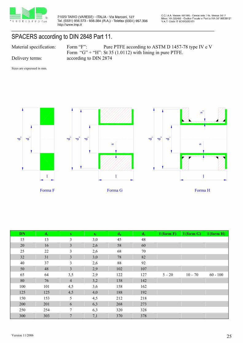
SPACERS according to DIN 2848 Part 11.
Material specification: Form “F”: Pure PTFE according to ASTM D 1457-78 type IV e V
Form “G” + “H”: St 35 (1.0112) with lining in pure PTFE.
Delivery terms: according to DIN 2874
Sizes are expressed in mm.
l l l
dd
15 1d
1ddd
45 5 4
d d
Forma F Forma G Forma H
s ss
f
DN d1 s sf d4 d5 l (form F) l (form G) l (form H)
15 13 3 3,0 45 48
20 16 3 2,6 58 60
25 22 3 2,6 68 70
32 31 3 3,0 78 82
40 37 3 2,6 88 92
50 48 3 2,9 102 107
65 64 3,5 2,9 122 127 5 – 20 10 – 70 60 - 100
80 76 4 3,2 138 142
100 101 4,5 3,6 158 162
125 125 4,5 4,0 188 192
150 153 5 4,5 212 218
200 201 6 6,3 268 273
250 254 7 6,3 320 328
300 303 7 7,1 370 378
Version 11/2006 26
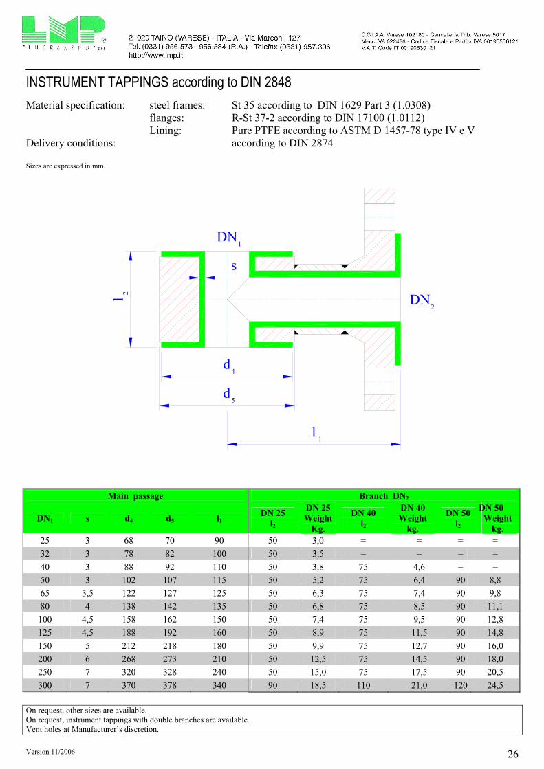
INSTRUMENT TAPPINGS according to DIN 2848
Material specification: steel frames: St 35 according to DIN 1629 Part 3 (1.0308)
flanges: R-St 37-2 according to DIN 17100 (1.0112)
Lining: Pure PTFE according to ASTM D 1457-78 type IV e V
Delivery conditions: according to DIN 2874
Sizes are expressed in mm.
s
d
d
l
l
4
5
1
2
DN1
DN2
Main passage Branch DN2
DN1 s d4 d5 l1 DN 25
l2
DN 25
Weight
Kg.
DN 40
l2
DN 40
Weight
kg.
DN 50
l2
DN 50
Weight
kg.
25 3 68 70 90 50 3,0 = = = =
32 3 78 82 100 50 3,5 = = = =
40 3 88 92 110 50 3,8 75 4,6 = =
50 3 102 107 115 50 5,2 75 6,4 90 8,8
65 3,5 122 127 125 50 6,3 75 7,4 90 9,8
80 4 138 142 135 50 6,8 75 8,5 90 11,1
100 4,5 158 162 150 50 7,4 75 9,5 90 12,8
125 4,5 188 192 160 50 8,9 75 11,5 90 14,8
150 5 212 218 180 50 9,9 75 12,7 90 16,0
200 6 268 273 210 50 12,5 75 14,5 90 18,0
250 7 320 328 240 50 15,0 75 17,5 90 20,5
300 7 370 378 340 90 18,5 110 21,0 120 24,5
On request, other sizes are available.
On request, instrument tappings with double branches are available.
Vent holes at Manufacturer’s discretion.

Version 11/2006 27
SIGHT GLASSES according to DIN 28121 ASSEMBLY LENGTH ACCORDING TO DIN 3202 Column F1
Material specification: Steel frames: St 35 according to DIN 1629 Part 3 (1.0308)
Flanges: R-St 37-2 according to DIN 17100 (1.0112)
Lining: Pure PTFE according to ASTM D 1457-78 type IV e V
Delivery terms: according to DIN 2874
Sizes are expressed in mm.
d
k
D
l
4
s
DN s d4 K D l Weight kg.
15 3 45 65 95 130 5,2
20 3 58 75 105 150 5,6
25 3 68 85 115 160 5,9
32 3 78 100 140 180 7,6
40 3 88 110 150 200 8,8
50 3 102 125 165 230 12,6
65 3,5 122 145 185 290 21,9
80 4 138 160 200 310 25,1
100 4,5 158 180 220 350 38,0
125 4,5 188 210 250 400 57,0
150 5 212 240 285 480 68,0
200 6 268 295 340 600 105,0
On request, “Heavy Duty” pieces are available for vacuum condition.
On request, glasses in borosilicate are available.
On request, other dimensions are available.
Vent holes at Manufacturer’s discretion.
Version 11/2006 28
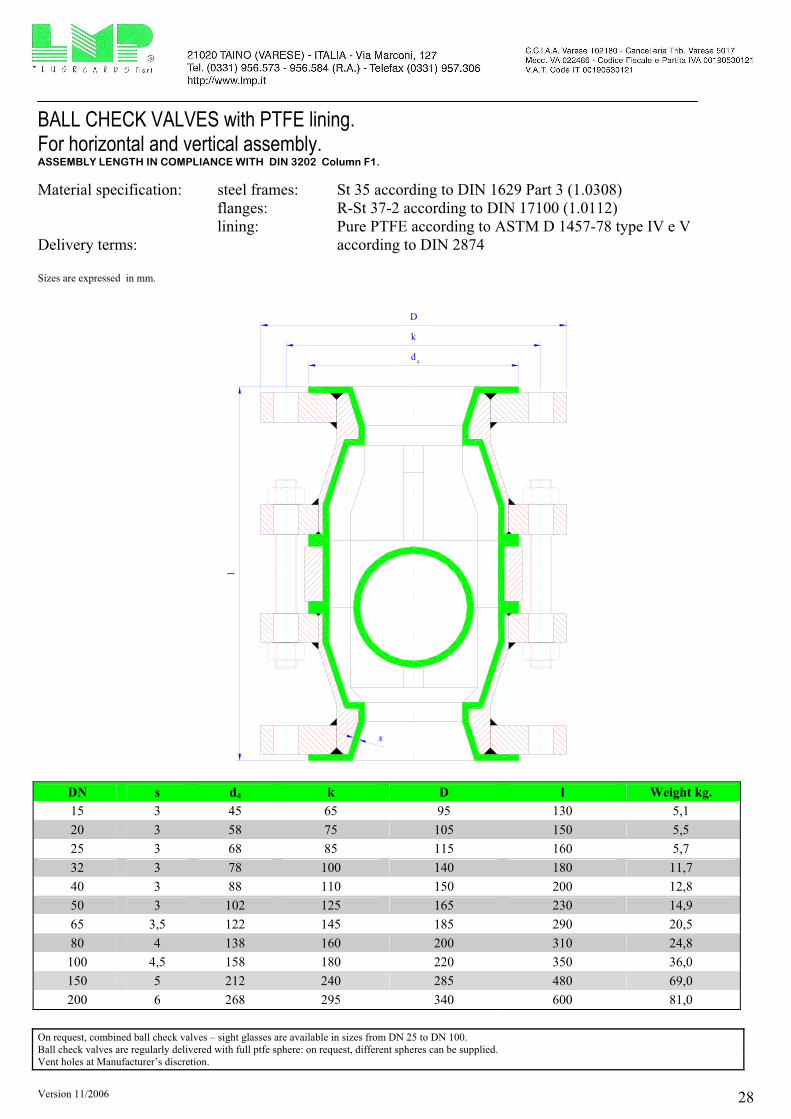
BALL CHECK VALVES with PTFE lining. For horizontal and vertical assembly. ASSEMBLY LENGTH IN COMPLIANCE WITH DIN 3202 Column F1.
Material specification: steel frames: St 35 according to DIN 1629 Part 3 (1.0308)
flanges: R-St 37-2 according to DIN 17100 (1.0112)
lining: Pure PTFE according to ASTM D 1457-78 type IV e V
Delivery terms: according to DIN 2874
Sizes are expressed in mm.
d
k
D
l
s
4
DN s d4 k D l Weight kg.
15 3 45 65 95 130 5,1
20 3 58 75 105 150 5,5
25 3 68 85 115 160 5,7
32 3 78 100 140 180 11,7
40 3 88 110 150 200 12,8
50 3 102 125 165 230 14,9
65 3,5 122 145 185 290 20,5
80 4 138 160 200 310 24,8
100 4,5 158 180 220 350 36,0
150 5 212 240 285 480 69,0
200 6 268 295 340 600 81,0
On request, combined ball check valves – sight glasses are available in sizes from DN 25 to DN 100.
Ball check valves are regularly delivered with full ptfe sphere: on request, different spheres can be supplied.
Vent holes at Manufacturer’s discretion.

Version 11/2006 29
Y STRAINERS with ptfe lining. ASSEMBLING LENGTH ACCORDING TO DIN 3202 Column F1
Material specification: Steel Frame: St 35 acc.to DIN 1629 Part 3 (1.0308)
Flanges: R-St 37-2 acc.to DIN 17100 (1.0112)
Lining: Pure PTFE acc.to ASTM D 1457-78 type IV e V
Filtering Basket: PTFE/glass or PTFE
Filtering net: PTFE
mesh: standard 210 micron, different sizes on request.
Delivery terms: acc.to DIN 2874
Sizes are expressed in mm.
dkD
s
l
4
1
DN s l1 d4 k D Weight kg.
25 3 160 68 85 115 5,2
40 3 200 88 110 150 11,8
50 3 230 102 125 165 14,9
80 4 310 138 160 200 22,8
100 4,5 350 158 180 220 30,5
150 5 480 212 240 285 56,0
200 6 600 268 295 340 88,0
Vent Holes at Manufacturer’s discretion.

Version 11/2006 30
INJECTION PIPES lined in PTFE according to DIN 2848
Material specification: Pipe: St 35 according to DIN 1629 Part 3 (1.0308)
Flange: R-St 37-2 according to DIN 17100 (1.0112)
Lining: Pure PTFE according to ASTM D 1457-78 type IV e V
Delivery terms: according to DIN 2874
Sizes are expressed in mm.
dDs
411
dkD
l
DN d4 k1 D1 D d l max
15 45 65 95 38 (29) 20 (13) 3000
20 58 75 105 38 20 3000
25 68 85 115 44 22 3000
32 78 100 140 54 31 3000
40 88 110 150 54 37 3000
50 102 125 165 70 48 3000
65 122 145 185 82 63 3000
80 138 160 200 107 75 3000
100 158 180 220 131 99 3000
125 188 210 250 159 122 3000
150 212 240 285 206 149 3000
200 268 295 340 238 194 3000
250 320 350 395 309 248 3000
On request, different sizes are available.
On request, different shapes and different final ends are available.
Vent holes at Manufacturer’s discretion.

Version 11/2006 31
PTFE INJECTION NOZZLE (without steel insert)
Material specification: Lining: Pure PTFE according to ASTM D 1457-78 type IV e V
Delivery terms: according to DIN 2848
Sizes are expressed in mm.
d
s
d
l
4 A
max.
DN s dA d4 l max
15 3 18 45 3.000
20 3 22 58 3.000
25 3 28 68 3.000
32 3 37 78 3.000
40 3 43 88 3.000
50 3 54 102 3.000
65 3,5 70 122 3.000
80 4 82 138 3.000
100 4,5 107 158 3.000
125 4,5 131 188 3.000
150 5 159 212 3.000
200 6 206 268 3.000
250 7 260 320 3.000
300 7 309 370 3.000
Version 11/2006 32
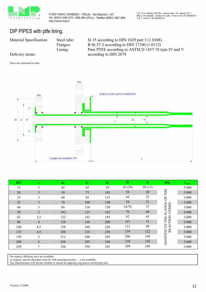
DIP PIPES with ptfe lining.
Material Specification: Steel tube: St 35 according to DIN 1629 part 3 (1.0308)
Flanges: R-St 37-2 according to DIN 17100 (1.0112)
Lining: Pure PTFE according to ASTM D 1457-78 type IV and V
Delivery terms: according to DIN 2874
Sizes are expressed in mm.
dkD
l
dDs
DN1
2DN
411
Lunghezza standard 150
ANELLO DI ADATTAMENTO
DN s d4 k1 D1 D d DN2 l max
15 3 45 65 95 38 (29) 20 (13) 3.000
20 3 58 75 105 38 20 3.000
25 3 68 85 115 44 22 3.000
32 3 78 100 140 54 31 3.000
40 3 88 110 150 54/70 37 3.000
50 3 102 125 165 70 48 3.000
65 3,5 122 145 185 82 63 3.000
80 4 138 160 200 107 75 3.000
100 4,5 158 180 220 131 99 3.000
125 4,5 188 210 250 159 122 3.000
150 5 212 240 285 206 149 3.000
200 6 268 295 340 238 194 3.000
250 7 320 350 395 309 248
AD
AP
TE
D T
O T
HE
FL
AN
GE
OF
TH
E
RE
AC
TIO
N V
ES
SE
L
3.000
On request, different sizes are available.
on request, special dip pipes (curved, with spraying nozzles,….) are available.
The Manufacturer will decide whether to mount an adapting ring and/or reinforcing tails.
Version 11/2006 33
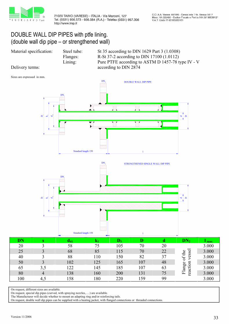
DOUBLE WALL DIP PIPES with ptfe lining. (double wall dip pipe – or strengthened wall)
Material specification: Steel tube: St 35 according to DIN 1629 Part 3 (1.0308)
Flanges: R-St 37-2 according to DIN 17100 (1.0112)
Lining: Pure PTFE according to ASTM D 1457-78 type IV - V
Delivery terms: according to DIN 2874
Sizes are expressed in mm.
l
dkD d D
DN1
2DN
41
11
Dd
l
41
1 1
D k d
DN1
2DN DOUBLE WALL DIP PIPE
STRENGTHENED SINGLE WALL DIP PIPE
Standard length 150
Standard length 150
DN s d41 k1 D1 D d DN2 l max
20 3 58 75 105 70 20 3.000
25 3 68 85 115 70 22 3.000
40 3 88 110 150 82 37 3.000
50 3 102 125 165 107 48 3.000
65 3,5 122 145 185 107 63 3.000
80 4 138 160 200 131 75 3.000
100 4,5 158 180 220 159 99
Fla
ng
e o
f th
e
reac
tio
n v
esse
l
3.000
On request, different sizes are available.
On request, special dip pipes (curved, with spraying nozzles,….) are available.
The Manufacturer will decide whether to mount an adapting ring and/or reinforcing tails.
On request, double wall dip pipes can be supplied with a heating jacket, with flanged connections or threaded connections.

Version 11/2006 34
EXPANSION JOINTS Material specification: Flanges: R-St 37-2 according to DIN 17100 (1.0112)
Lining: “TFM”® (produced by Dyneon )
Delivery terms: according to DIN 2874 Sizes are expressed in mm.
d
d4
k
lD
n x d2
120°
Remarks: DO NOT remove the limiting stud bolts of the expansion joints.
DN d d4 k n x d2 D l for 2
conv.
l for 3
conv.
l for 4
conv.
l for 5
conv.
l for 6
conv.
l for 7
conv.
l for 8
conv.
15 22 45 65 4 x M12 95 38 50 62 74 86 98 110
20 22 58 75 4 x M12 105 38 50 62 74 86 98 110
25 22 68 85 4 x M12 115 41 55 69 83 97 111 125
32 31 78 100 4 x M16 140 41 55 69 83 97 111 125
40 37 88 110 4 x M16 150 51 65 79 93 107 121 135
50 48 102 125 4 x M16 165 56 70 84 98 112 126 140
65 63 122 145 4 x M16 185 54 70 86 102 118 134 150
80 75 138 160 8 x M16 200 54 70 86 102 118 134 150
100 99 158 180 8 x M16 220 82 100 118 136 154 172 190
125 122 188 210 8 x M16 250 82 100 118 136 154 172 190
150 149 212 240 8 x M20 285 87 105 123 141 159 177 195
200 194 268 295 8 x M20 340 86 105 124 143 162 181 200
250 248 320 350 12 x M20 395 78 105 132 159 186 N.A.. N.A.
300 297 370 400 12 x M20 445 78 105 132 159 186 N.A. N.A.
350 325 430 460 16 x M20 505 78 105 132 159 186 N.A. N.A.
400 376 482 515 16 x M22 565 93 120 147 174 201 N.A. N.A.
450 420 532 565 20 x M22 615 93 120 147 174 201 N.A. N.A.
500 471 585 620 20 x M22 670 93 120 147 174 201 N.A. N.A.
600 595 685 725 20 x M27 780 81 100 N.A. N.A. N.A. N.A. N.A.
N.A. = not available.
Flanges are according to DIN PN 16 from DN 15 to DN 150 (included) and DIN PN 10 from DN 200 onwards. All sizes are provided with threaded holes (passing through). All the expansion joints are moulded in “TFM”® (made by Dyneon), with mechanical properties absolutely superior than the traditional PTFE. The expansion joints are supplied with 3 stud bolts for the limit stop at 120° on diameter: DO NOT REMOVE THE LIMITING STUD BOLTS. Each convolutions is provided with a stainless steel reinforcing ring, for better performances. The movement of each convolution is +12 mm (expansion) / -8 mm (compression), longitudinally. On request, it is possible to supply expansion joints with stainless steel flanges. Special sizes shall be required to the Manufacturer.

Version 11/2006 35
FLANGED PIPES according to ANSI B16.5 class 150.
Material specification: Tubes: ASTM A106 gr.B according to ANSI B36.10
API 5L gr.B according to ANSI B36.10
Flanges: ASTM A105 according to ANSI B16.5
Lining: Pure PTFE according to ASTM-D 4894 - 4895
Delivery terms: according to DIN 2874
Sizes are expressed in mm.
L DN 15 ÷ 300: 3.000max.
d d1
d4
k
h h
d2
1 2
D
s f
s
DN d1 sf d s n x d2 d4 k D h1 h2
½“ 24 3,0 12 3 4 x 15,9 35 60,3 88,9 13,6 23,1
¾“ 24 3,0 12 3 4 x 15,9 43 69,8 98,4 15,2 26,3
1“ 33,4 3,38 19 3 4 x 15,9 51 79,4 107,9 17,3 28,4
1¼“ 42,2 3,56 28 3 4 x 15,9 64 88,9 117,5 18,9 30,0
1½“ 48,3 3,68 32 3 4 x 15,9 73 98,4 127,0 20,5 31,6
2“ 60,3 3,91 44 3 4 x 19,0 92 120,6 152,4 22,1 36,2
2½“ 73 5,16 61 3,5 4 x 19,0 105 139,7 177,8 25,2 39,4
3“ 88,9 5,49 69 4 4 x 19,0 127 152,4 190,5 26,8 42,6
4“ 114,3 6,02 94 4,5 8 x 19,0 157 190,5 228,6 26,8 42,6
5“ 141,3 6,55 121 4,5 8 x 22,2 185 215,9 254,0 26,8 44,2
6“ 168,3 7,11 144 5 8 x 22,2 216 241,3 279,4 30,4 46,3
8“ 219,1 6,35 194 6 8 x 22,2 270 298,4 342,9 33,1 53,7
10“ 273 6,35 246 7 12 x 25,4 324 361,9 406,4 35,2 57,4
12“ 323,8 6,35 297 7 12 x 25,4 381 431,8 482,6 36,8 58,9
Steel tube schedule 40 up to 6” (included), schedule 20 from 8” and above.
On request, “Heavy Duty” pieces are available for vacuum condition. Vent holes at Manufacturer’s discretion.
Weights in Kgs.
Size ½” ¾” 1” 1¼” 1½” 2” 2½” 3” 4” 5” 6” 8” 10” 12”
1 meter pipe 1,6 2,1 2,8 3,7 4,2 5,8 7,8 9,9 14,5 20,7 23,4 39,1 51,7 67,7
loose+fixed flange 1,7 2,3 3,0 4,2 4,8 6,7 9,0 11,4 11,7 15,6 20,3 34,0 44,3 68,4

Version 11/2006 36
FLANGED 45° BENDS according to ANSI B16.5 class 150.
Material specification: Steel frames: ASTM A234 gr. WPB, according to ANSI B16.28
Flanges: ASTM A105, according to ANSI B16.5
Lining: Pure PTFE, according to ASTM-D 4894
Delivery terms: according to DIN 2874
Sizes are expressed in mm.
D
k
d
l /l
3
4
l /l
3
4
r
4
s
DN s Type of elbow r l3 l4 d4 k D Weight kg.
½“ 3 L. R. 38,1 45 35 60,3 88,9 2,2
¾“ 3 L. R. 28,6 45 43 69,8 98,4 2,5
1“ 3 L. R. 38,1 45 51 79,4 107,9 3,0
1¼“ 3 L. R. 47,6 51 64 88,9 117,5 4,4
1½“ 3 L. R. 57,2 57 73 98,4 127,0 4,8
2“ 3 L. R. 76,2 64 92 120,6 152,4 6,3
2½“ 3,5 S.R. 63,5 76 105 139,7 177,8 8,3
3“ 4 S.R. 76,2 76 127 152,4 190,5 11,5
4“ 4,5 S.R. 101,6 102 157 190,5 228,6 13,8
5“ 4,5 S.R. 127,0 114 185 215,9 254,0 19,6
6“ 5 S.R. 152,4 127 216 241,3 279,4 28,3
8“ 6 S.R. 203,2 140 270 298,4 342,9 47,6
10“ 7 S.R. 254,0 165 324 361,9 406,4 72,4
12“ 7 S.R. 304,8 190 381 431,8 482,6 106,4
On request, “Heavy Duty” pieces are available for vacuum condition .
Steel frames are according to schedule 40.
On request, bends with different angles are available.
Vent holes at Manufacturer’s discretion.

Version 11/2006 37
FLANGED 90° BENDS according to ANSI B16.5 class 150.
Material specification: Steel frames: ASTM A234 gr. WPB, according to ANSI B16.28
Flanges: ASTM A105, according to ANSI B16.5
Lining: Pure PTFE, according to ASTM-D 4894
Delivery terms: according to DIN 2874
Sizes are expressed in mm.
l /l 1 2
l /l
21
r
d
k Ds
4
DN s Type of elbow r l1 l2 d4 k D Weight kg.
½“ 3 L. R. 38,1 65 35 60,3 88,9 2,3
¾“ 3 L. R. 28,6 75 43 69,8 98,4 2,6
1“ 3 L. R. 38,1 89 51 79,4 107,9 3,3
1¼“ 3 L. R. 47,6 95 64 88,9 117,5 4,6
1½“ 3 L. R. 57,2 102 73 98,4 127,0 5,2
2“ 3 L. R. 76,2 114 92 120,6 152,4 6,9
2½“ 3,5 S.R. 63,5 127 105 139,7 177,8 9,1
3“ 4 S.R. 76,2 140 127 152,4 190,5 11,9
4“ 4,5 S.R. 101,6 165 157 190,5 228,6 14,5
5“ 4,5 S.R. 127,0 190 185 215,9 254,0 21,8
6“ 5 S.R. 152,4 203 216 241,3 279,4 32,0
8“ 6 S.R. 203,2 229 270 298,4 342,9 62,7
10“ 7 S.R. 254,0 279 324 361,9 406,4 94,6
12“ 7 S.R. 304,8 305 381 431,8 482,6 140,4
On request, “Heavy Duty” pieces are available for vacuum condition .
Steel frames are according to schedule 40.
On request, bends with different angles are available.
Vent holes at Manufacturer’s discretion.

Version 11/2006 38
EQUAL AND REDUCING TEE PIECES according to ANSI B16.5 class 150.
Material specification: Steel frame: ASTM A234 gr. WPB, according to ANSI B16.28
Flanges: ASTM A105, according to ANSI B16.5
Lining: Pure PTFE, according to ASTM-D 4894
Delivery terms: according to DIN 2874
Sizes are expressed in mm.
dkD
D
k
d
l
l l
DN
DN
1
2
42
2
2
1 1
41
11
2
s1
s2
DN1 s1 l1 d41 k1 D1 DN2 s2 l2 d42 k2 D2 Weight
Kg. ½” 3 65 35 60,3 88,9 ½” 2,7
¾” 3 75 43 69,8 98,4 ¾” 3,8
¾” 3 75 43 69,8 98,4 ½” 3 75 35 60,3 88,9 3,1
1” 3 89 51 79,4 107,9 1” 5,0
1” 3 89 51 79,4 107,9 ¾” 3 89 43 69,8 98,4 4,6
1” 3 89 51 79,4 107,9 ½” 3 89 35 60,3 88,9 4,1
1¼” 3 95 64 88,9 117,5 1¼” 7,4
1¼” 3 95 64 88,9 117,5 1” 3 95 51 79,4 107,9 7,0
1¼” 3 95 64 88,9 117,5 ¾” 3 95 43 69,8 98,4 6,7
1¼” 3 95 64 88,9 117,5 ½” 3 95 35 60,3 88,9 6,3
1½” 3 102 73 98,4 127,0 1½” 8,9
1½” 3 102 73 98,4 127,0 1¼” 3 102 64 88,9 117,5 8,6
1½” 3 102 73 98,4 127,0 1” 3 102 51 79,4 107,9 8,1
1½” 3 102 73 98,4 127,0 ¾” 3 102 43 69,8 98,4 7,8
1½” 3 102 73 98,4 127,0 ½” 3 102 35 60,3 88,9 7,5

Version 11/2006 39
EQUAL AND REDUCING TEE PIECES according to ANSI B16.5 class 150.
Material specification: Steel frame: ASTM A234 gr. WPB, according to ANSI B16.28
Flanges: ASTM A105, according to ANSI B16.5
Lining: Pure PTFE, according to ASTM-D 4894
Delivery terms: according to DIN 2874
Sizes are expressed in mm.
DN1 s1 l1 d41 k1 D1 DN2 s2 l2 d42 k2 D2 Weight
Kg. 2” 3 114 92 120,6 152,4 2” 11,0
2” 3 114 92 120,6 152,4 1½” 3 114 73 98,4 127,0 9,7
2” 3 114 92 120,6 152,4 1¼” 3 114 64 88,9 117,5 9,1
2” 3 114 92 120,6 152,4 1” 3 114 51 79,4 107,9 8,7
2” 3 114 92 120,6 152,4 ¾” 3 114 43 69,8 98,4 8,4
2” 3 114 92 120,6 152,4 ½” 3 114 35 60,3 88,9 8,0
2½” 3,5 127 105 139,7 177,8 2½” 13,5
2½” 3,5 127 105 139,7 177,8 2” 3 127 92 120,6 152,4 12,6
2½” 3,5 127 105 139,7 177,8 1½” 3 127 73 98,4 127,0 11,7
2½” 3,5 127 105 139,7 177,8 1¼” 3 127 64 88,9 117,5 11,0
2½” 3,5 127 105 139,7 177,8 1” 3 127 51 79,4 107,9 10,3
2½” 3,5 127 105 139,7 177,8 ¾” 3 127 43 69,8 98,4 9,8
2½” 3,5 127 105 139,7 177,8 ½” 3 127 35 60,3 88,9 9,5
3” 4 140 127 152,4 190,5 3” 19,4
3” 4 140 127 152,4 190,5 2½” 3,5 140 105 139,7 177,8 17,2
3” 4 140 127 152,4 190,5 2” 3 140 92 120,6 152,4 15,9
3” 4 140 127 152,4 190,5 1½” 3 140 73 98,4 127,0 15,0
3” 4 140 127 152,4 190,5 1¼” 3 140 64 88,9 117,5 14,4
3” 4 140 127 152,4 190,5 1” 3 140 51 79,4 107,9 14,0
3” 4 140 127 152,4 190,5 ¾” 3 140 43 69,8 98,4 13,3
3” 4 140 127 152,4 190,5 ½” 3 140 35 60,3 88,9 12,6
4” 4,5 165 157 190,5 228,6 4” 23,8
4” 4,5 165 157 190,5 228,6 3” 4 165 127 152,4 190,5 22,0
4” 4,5 165 157 190,5 228,6 2½” 3,5 165 105 139,7 177,8 20,8
4” 4,5 165 157 190,5 228,6 2” 3 165 92 120,6 152,4 19,6
4” 4,5 165 157 190,5 228,6 1½” 3 165 73 98,4 127,0 18,7
4” 4,5 165 157 190,5 228,6 1¼” 3 165 64 88,9 117,5 17,7
4” 4,5 165 157 190,5 228,6 1” 3 165 51 79,4 107,9 17,2
4” 4,5 165 157 190,5 228,6 ¾” 3 165 43 69,8 98,4 16,5
4” 4,5 165 157 190,5 228,6 ½” 3 165 35 60,3 88,9 16,1
5” 4,5 190 185 215,9 254,0 5” 36,0
5” 4,5 190 185 215,9 254,0 4” 4,5 190 157 190,5 228,6 34,5
5” 4,5 190 185 215,9 254,0 3” 4 190 127 152,4 190,5 33,2
5” 4,5 190 185 215,9 254,0 2½” 3,5 190 105 139,7 177,8 32,2
5” 4,5 190 185 215,9 254,0 2” 3 190 92 120,6 152,4 31,3
5” 4,5 190 185 215,9 254,0 1½” 3 190 73 98,4 127,0 30,4
5” 4,5 190 185 215,9 254,0 1¼” 3 190 64 88,9 117,5 29,5
5” 4,5 190 185 215,9 254,0 1” 3 190 51 79,4 107,9 28,7

Version 11/2006 40
EQUAL AND REDUCING TEE PIECES according to ANSI B16.5 class 150.
Material specification: Steel frame: ASTM A234 gr. WPB, according to ANSI B16.28
Flanges: ASTM A105, according to ANSI B16.5
Lining: Pure PTFE, according to ASTM-D 4894
Delivery terms: according to DIN 2874
Sizes are expressed in mm.
DN1 s1 l1 d41 k1 D1 DN2 s2 l2 d42 k2 D2 Weight
Kg. 6” 5 203 216 241,3 279,4 6” 50,8
6” 5 203 216 241,3 279,4 5” 4,5 203 185 215,9 254,0 46,7
6” 5 203 216 241,3 279,4 4” 4,5 203 157 190,5 228,6 42,2
6” 5 203 216 241,3 279,4 3” 4 203 127 152,4 190,5 40,8
6” 5 203 216 241,3 279,4 2½” 3,5 203 105 139,7 177,8 39,4
6” 5 203 216 241,3 279,4 2” 3 203 92 120,6 152,4 38,1
6” 5 203 216 241,3 279,4 1½” 3 203 73 98,4 127,0 36,9
6” 5 203 216 241,3 279,4 1¼” 3 203 64 88,9 117,5 35,8
6” 5 203 216 241,3 279,4 1” 3 203 51 79,4 107,9 34,8
8” 6 229 270 298,4 342,9 8” 89,9
8” 6 229 270 298,4 342,9 6” 5 229 216 241,3 279,4 75,6
8” 6 229 270 298,4 342,9 5” 4,5 229 185 215,9 254,0 74,6
8” 6 229 270 298,4 342,9 4” 4,5 229 157 190,5 228,6 70,6
8” 6 229 270 298,4 342,9 3” 4 229 127 152,4 190,5 66,6
8” 6 229 270 298,4 342,9 2½” 3,5 229 105 139,7 177,8 62,6
8” 6 229 270 298,4 342,9 2” 3 229 92 120,6 152,4 58,6
10” 7 279 324 361,9 406,4 10” 131,6
10” 7 279 324 361,9 406,4 8” 6 279 270 298,4 342,9 112,4
10” 7 279 324 361,9 406,4 6” 5 279 216 241,3 279,4 107,4
10” 7 279 324 361,9 406,4 5” 4,5 279 185 215,9 254,0 103,4
10” 7 279 324 361,9 406,4 4” 4,5 279 157 190,5 228,6 99,4
10” 7 279 324 361,9 406,4 3” 4 279 127 152,4 190,5 94,4
10” 7 279 324 361,9 406,4 2½” 3,5 279 105 139,7 177,8 89,4
10” 7 279 324 361,9 406,4 2” 3 279 92 120,6 152,4 84,4
12” 7 305 381 431,8 482,6 12” 193,6
12” 7 305 381 431,8 482,6 10” 7 305 324 361,9 406,4 164,4
12” 7 305 381 431,8 482,6 8” 6 305 270 298,4 342,9 156,4
12” 7 305 381 431,8 482,6 6” 5 305 216 241,3 279,4 151,4
12” 7 305 381 431,8 482,6 5” 4,5 305 185 215,9 254,0 146,4
12” 7 305 381 431,8 482,6 4” 4,5 305 157 190,5 228,6 142,4
12” 7 305 381 431,8 482,6 3” 4 305 127 152,4 190,5 138,4
12” 7 305 381 431,8 482,6 2½” 3,5 305 105 139,7 177,8 135,4
12” 7 305 381 431,8 482,6 2” 3 305 92 120,6 152,4 131,4
On request, “Heavy Duty” pieces are available for vacuum condition .
Steel frames are according to schedule 40.
Vent holes at Manufacturer’s discretion.

Version 11/2006 41
45° LATERAL TEES according to ANSI B16.5 class 150.
Material specification: Steel frame: A106 gr.B, API 5L gr.B, according to ANSI B36.10
Flanges: ASTM A105, according to ANSI B16.5
Lining: Pure PTFE, according to ASTM-D 4894
Delivery terms: according to DIN 2874
Sizes are expressed in mm.
l l
l
k d D
2 1
1
4
45°
s
DN s l1 l2 d4 k D Weight kg.
1“ 3 180 40 51 79,4 107,9 4,8
1¼“ 3 210 45 64 88,9 117,5 7,0
1½“ 3 220 50 73 98,4 127,0 8,6
2“ 3 240 55 92 120,6 152,4 10,7
2½“ 3,5 260 60 105 139,7 177,8 12,9
3“ 4 290 70 127 152,4 190,5 18,7
4“ 4,5 320 80 157 190,5 228,6 22,8
5“ 4,5 350 90 185 215,9 254,0 34,6
6“ 5 380 100 216 241,3 279,4 50,0
8“ 6 455 120 270 298,4 342,9 89,9
Steel frames are according to schedule 40.
On request, “Heavy Duty” pieces are available for vacuum condition .
Reduced lateral tees and/or lateral tees with different angles can be taken into account.
Vent holes at Manufacturer’s discretion.

Version 11/2006 42
EQUAL AND REDUCING CROSSES according to ANSI B16.5 class 150.
Material specification: Steel frame: ASTM A234 gr. WPB, according to ANSI B16.28
Flanges: ASTM A105, according to ANSI B16.5
Lining: Pure PTFE, according to ASTM-D 4894
Delivery terms: according to DIN 2874
Sizes are expressed in mm.
d 42
k
D
2
2
D k d 1 1 4
1
l l 1 1
l 2l 2
DN1
DN2
s1
s2
DN1 s1 l1 d41 k1 D1 DN2 s2 l2 d42 k2 D2 Weight
kg. ½” 3 65 35 60,3 88,9 ½” 3 65 35 60,3 88,9 3,5
¾” 3 75 43 69,8 98,4 ¾” 3 75 43 69,8 98,4 4,7
¾” 3 75 43 69,8 98,4 ½” 3 75 35 60,3 88,9 3,7
1” 3 89 51 79,4 107,9 1” 3 89 51 79,4 107,9 5,5
1” 3 89 51 79,4 107,9 ¾” 3 89 43 69,8 98,4 5,1
1” 3 89 51 79,4 107,9 ½” 3 89 35 60,3 88,9 4,8
1¼” 3 95 64 88,9 117,5 1¼” 3 95 64 88,9 117,5 7,0
1¼” 3 95 64 88,9 117,5 1” 3 95 51 79,4 107,9 6,1
1¼” 3 95 64 88,9 117,5 ¾” 3 95 43 69,8 98,4 5,2
1¼” 3 95 64 88,9 117,5 ½” 3 95 35 60,3 88,9 4,2
1½” 3 102 73 98,4 127,0 1½” 3 102 73 98,4 127,0 9,4
1½” 3 102 73 98,4 127,0 1¼” 3 102 64 88,9 117,5 9,2
1½” 3 102 73 98,4 127,0 1” 3 102 51 79,4 107,9 8,9
1½” 3 102 73 98,4 127,0 ¾” 3 102 43 69,8 98,4 8,6
1½” 3 102 73 98,4 127,0 ½” 3 102 35 60,3 88,9 8,2

Version 11/2006 43
EQUAL AND REDUCING CROSSES according to ANSI B16.5 class 150.
Material specification: Steel frame: ASTM A234 gr. WPB, according to ANSI B16.28
Flanges: ASTM A105, according to ANSI B16.5
Lining: Pure PTFE, according to ASTM-D 4894
Delivery terms: according to DIN 2874
Sizes are expressed in mm.
DN1 s1 l1 d41 k1 D1 DN2 s2 l2 d42 k2 D2
Weight
kg. 2” 3 114 92 120,6 152,4 2” 3 114 92 120,6 152,4 12,3
2” 3 114 92 120,6 152,4 1½” 3 114 73 98,4 127,0 11,4
2” 3 114 92 120,6 152,4 1¼” 3 114 64 88,9 117,5 10,7
2” 3 114 92 120,6 152,4 1” 3 114 51 79,4 107,9 10,2
2” 3 114 92 120,6 152,4 ¾” 3 114 43 69,8 98,4 9,7
2” 3 114 92 120,6 152,4 ½” 3 114 35 60,3 88,9 9,3
2½” 3,5 127 105 139,7 177,8 2½” 3,5 127 105 139,7 177,8 16,5
2½” 3,5 127 105 139,7 177,8 2” 3 127 92 120,6 152,4 14,8
2½” 3,5 127 105 139,7 177,8 1½” 3 127 73 98,4 127,0 13,8
2½” 3,5 127 105 139,7 177,8 1¼” 3 127 64 88,9 117,5 12,7
2½” 3,5 127 105 139,7 177,8 1” 3 127 51 79,4 107,9 11,7
2½” 3,5 127 105 139,7 177,8 ¾” 3 127 43 69,8 98,4 10,7
2½” 3,5 127 105 139,7 177,8 ½” 3 127 35 60,3 88,9 9,8
3” 4 140 127 152,4 190,5 3” 4 140 127 152,4 190,5 30,8
3” 4 140 127 152,4 190,5 2½” 3,5 140 105 139,7 177,8 29,3
3” 4 140 127 152,4 190,5 2” 3 140 92 120,6 152,4 26,7
3” 4 140 127 152,4 190,5 1½” 3 140 73 98,4 127,0 25,3
3” 4 140 127 152,4 190,5 1¼” 3 140 64 88,9 117,5 24,0
3” 4 140 127 152,4 190,5 1” 3 140 51 79,4 107,9 23,0
3” 4 140 127 152,4 190,5 ¾” 3 140 43 69,8 98,4 22,1
3” 4 140 127 152,4 190,5 ½” 3 140 35 60,3 88,9 21,1
4” 4,5 165 157 190,5 228,6 4” 4,5 165 157 190,5 228,6 46,2
4” 4,5 165 157 190,5 228,6 3” 4 165 127 152,4 190,5 41,1
4” 4,5 165 157 190,5 228,6 2½” 3,5 165 105 139,7 177,8 37,3
4” 4,5 165 157 190,5 228,6 2” 3 165 92 120,6 152,4 33,0
4” 4,5 165 157 190,5 228,6 1½” 3 165 73 98,4 127,0 29,6
4” 4,5 165 157 190,5 228,6 1¼” 3 165 64 88,9 117,5 27,5
4” 4,5 165 157 190,5 228,6 1” 3 165 51 79,4 107,9 23,0
4” 4,5 165 157 190,5 228,6 ¾” 3 165 43 69,8 98,4 21,4
4” 4,5 165 157 190,5 228,6 ½” 3 165 35 60,3 88,9 19,6
5” 4,5 190 185 215,9 254,0 5” 4,5 190 185 215,9 254,0 59,8
5” 4,5 190 185 215,9 254,0 4” 4,5 190 157 190,5 228,6 54,6
5” 4,5 190 185 215,9 254,0 3” 4 190 127 152,4 190,5 50,2
5” 4,5 190 185 215,9 254,0 2½” 3,5 190 105 139,7 177,8 46,6
5” 4,5 190 185 215,9 254,0 2” 3 190 92 120,6 152,4 43,1
5” 4,5 190 185 215,9 254,0 1½” 3 190 73 98,4 127,0 39,4
5” 4,5 190 185 215,9 254,0 1¼” 3 190 64 88,9 117,5 36,6
5” 4,5 190 185 215,9 254,0 1” 3 190 51 79,4 107,9 33,0

Version 11/2006 44
EQUAL AND REDUCING CROSSES according to ANSI B16.5 class 150.
Material specification: Steel frame: ASTM A234 gr. WPB, according to ANSI B16.28
Flanges: ASTM A105, according to ANSI B16.5
Lining: Pure PTFE, according to ASTM-D 4894
Delivery terms: according to DIN 2874
Sizes are expressed in mm.
DN1 s1 l1 d41 k1 D1 DN2 s2 l2 d42 k2 D2
Weight
kg.
6” 5 203 216 241,3 279,4 6” 5 203 216 241,3 279,4 76,5
6” 5 203 216 241,3 279,4 5” 4,5 203 185 215,9 254,0 64,7
6” 5 203 216 241,3 279,4 4” 4,5 203 157 190,5 228,6 58,5
6” 5 203 216 241,3 279,4 3” 4 203 127 152,4 190,5 53,8
6” 5 203 216 241,3 279,4 2½” 3,5 203 105 139,7 177,8 49,2
6” 5 203 216 241,3 279,4 2” 3 203 92 120,6 152,4 45,7
6” 5 203 216 241,3 279,4 1½” 3 203 73 98,4 127,0 42,1
6” 5 203 216 241,3 279,4 1¼” 3 203 64 88,9 117,5 41,9
6” 5 203 216 241,3 279,4 1” 3 203 51 79,4 107,9 37,5
8” 6 229 270 298,4 342,9 8” 6 229 270 298,4 342,9 147,2
8” 6 229 270 298,4 342,9 6” 5 229 216 241,3 279,4 101,1
8” 6 229 270 298,4 342,9 5” 4,5 229 185 215,9 254,0 94,1
8” 6 229 270 298,4 342,9 4” 4,5 229 157 190,5 228,6 86,6
8” 6 229 270 298,4 342,9 3” 4 229 127 152,4 190,5 79,6
8” 6 229 270 298,4 342,9 2½” 3,5 229 105 139,7 177,8 73,1
8” 6 229 270 298,4 342,9 2” 3 229 92 120,6 152,4 67,1
10” 7 279 324 361,9 406,4 10” 7 279 324 361,9 406,4 204,8
10” 7 279 324 361,9 406,4 8” 6 279 270 298,4 342,9 149,4
10” 7 279 324 361,9 406,4 6” 5 279 216 241,3 279,4 131,4
10” 7 279 324 361,9 406,4 5” 4,5 279 185 215,9 254,0 124,9
10” 7 279 324 361,9 406,4 4” 4,5 279 157 190,5 228,6 118,9
10” 7 279 324 361,9 406,4 3” 4 279 127 152,4 190,5 113,4
10” 7 279 324 361,9 406,4 2½” 3,5 279 105 139,7 177,8 108,9
10” 7 279 324 361,9 406,4 2” 3 279 92 120,6 152,4 102,9
12” 7 305 381 431,8 482,6 12” 7 305 381 431,8 482,6 285,3
12” 7 305 381 431,8 482,6 10” 7 305 324 361,9 406,4 214,4
12” 7 305 381 431,8 482,6 8” 6 305 270 298,4 342,9 199,4
12” 7 305 381 431,8 482,6 6” 5 305 216 241,3 279,4 182,4
12” 7 305 381 431,8 482,6 5” 4,5 305 185 215,9 254,0 167,4
12” 7 305 381 431,8 482,6 4” 4,5 305 157 190,5 228,6 153,4
12” 7 305 381 431,8 482,6 3” 4 305 127 152,4 190,5 140,4
12” 7 305 381 431,8 482,6 2½” 3,5 305 105 139,7 177,8 127,9
12” 7 305 381 431,8 482,6 2” 3 305 92 120,6 152,4 115,9
On request, “Heavy Duty” pieces are available for vacuum condition .
Steel frames are according to schedule 40.
Vent holes at Manufacturer’s discretion.

Version 11/2006 45
FLANGED REDUCERS according to ANSI B16.5 class 150. CONCENTRIC / ECCENTRIC
Material specification: Steel frame: ASTM A234 gr. WPB, according to ANSI B16.28
Flanges: ASTM A105, according to ANSI B16.5
Lining: Pure PTFE, according to ASTM-D 4894
Delivery terms: according to DIN 2874
Sizes are expressed in mm.
l l3 3
kD
11
D k
1 1
k D22
Dk2 2
DN1
DN2
DN1
DN2
e
s
s
1
2
s1
2s
DN1 s1 DN2 s2 e l3 K1 D1 k2 D2 Weight kg.
¾“ 3 ½“ 3 3 114 69,8 98,4 60,3 88,9 2,4
1“ 3 ¾“ 3 3 114 79,4 107,9 69,8 98,4 2,6
1“ 3 ½“ 3 3 114 79,4 107,9 60,3 88,9 2,5
1¼“ 3 1“ 3 4 114 88,9 117,5 79,4 107,9 3,5
1¼“ 3 ¾“ 3 4 114 88,9 117,5 69,8 98,4 3,3
1¼“ 3 ½“ 3 4 114 88,9 117,5 60,3 88,9 2,8
1½“ 3 1¼“ 3 3 114 98,4 127,0 88,9 117,5 4,9
1½“ 3 ¾“ 3 7 114 98,4 127,0 69,8 98,4 3,9
1½“ 3 1“ 3 7 114 98,4 127,0 79,4 107,9 2,8
1½“ 3 ½“ 3 7 114 98,4 127,0 60,3 88,9 2,0
2“ 3 1½“ 3 6 127 120,6 152,4 98,4 127,0 6,1
2“ 3 1¼“ 3 9 127 120,6 152,4 88,9 117,5 5,5
2“ 3 1“ 3 13 127 120,6 152,4 79,4 107,9 4,9
2“ 3 ¾“ 3 13 127 120,6 152,4 69,8 98,4 4,3
2“ 3 ½“ 3 13 127 120,6 152,4 60,3 88,9 3,4
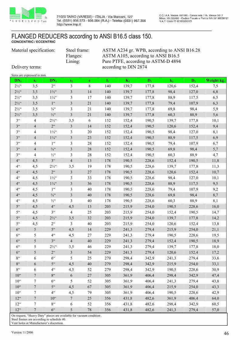
Version 11/2006 46
FLANGED REDUCERS according to ANSI B16.5 class 150. CONCENTRIC / ECCENTRIC
Material specification: Steel frame: ASTM A234 gr. WPB, according to ANSI B16.28
Flanges: ASTM A105, according to ANSI B16.5
Lining: Pure PTFE, according to ASTM-D 4894
Delivery terms: according to DIN 2874
Sizes are expressed in mm.
DN1 s1 DN2 s2 e l3 K1 D1 k2 D2 Weight kg.
2½“ 3,5 2“ 3 8 140 139,7 177,8 120,6 152,4 7,5
2½“ 3,5 1½“ 3 14 140 139,7 177,8 98,4 127,0 6,8
2½“ 3,5 1¼“ 3 17 140 139,7 177,8 88,9 117,5 6,5
2½“ 3,5 1“ 3 21 140 139,7 177,8 79,4 107,9 6,3
2½“ 3,5 ¾“ 3 21 140 139,7 177,8 69,8 98,4 5,9
2½“ 3,5 ½“ 3 21 140 139,7 177,8 60,3 88,9 5,6
3“ 4 2½“ 3,5 6 152 152,4 190,5 139,7 177,8 10,1
3“ 4 2“ 3 14 152 152,4 190,5 120,6 152,4 9,4
3“ 4 1½“ 3 20 152 152,4 190,5 98,4 127,0 8,1
3“ 4 1¼“ 3 23 152 152,4 190,5 88,9 117,5 6,9
3“ 4 1“ 3 28 152 152,4 190,5 79,4 107,9 6,7
3“ 4 ¾“ 3 28 152 152,4 190,5 69,8 98,4 5,7
3“ 4 ½“ 3 28 152 152,4 190,5 60,3 88,9 4,7
4“ 4,5 3“ 4 13 178 190,5 228,6 152,4 190,5 11,8
4“ 4,5 2½“ 3,5 19 178 190,5 228,6 139,7 177,8 11,3
4“ 4,5 2“ 3 27 178 190,5 228,6 120,6 152,4 10,7
4“ 4,5 1½“ 3 33 178 190,5 228,6 98,4 127,0 10,1
4“ 4,5 1¼“ 3 36 178 190,5 228,6 88,9 117,5 9,5
4“ 4,5 1“ 3 40 178 190,5 228,6 79,4 107,9 9,2
4“ 4,5 ¾“ 3 40 178 190,5 228,6 69,8 98,4 8,7
4“ 4,5 ½“ 3 40 178 190,5 228,6 60,3 88,9 8,1
5“ 4,5 4“ 4,5 13 203 215,9 254,0 190,5 228,6 16,0
5“ 4,5 3“ 4 25 203 215,9 254,0 152,4 190,5 14,7
5“ 4,5 2½“ 3,5 32 203 215,9 254,0 139,7 177,8 14,2
5“ 4,5 2“ 3 40 203 215,9 254,0 120,6 152,4 13,8
6“ 5 5“ 4,5 14 229 241,3 279,4 215,9 254,0 21,1
6“ 5 4“ 4,5 27 229 241,3 279,4 190,5 228,6 19,5
6“ 5 3“ 4 40 229 241,3 279,4 152,4 190,5 18,9
6“ 5 2½“ 3,5 46 229 241,3 279,4 139,7 177,8 18,0
6“ 5 2“ 3 54 229 241,3 279,4 120,6 152,4 17,2
8“ 6 6“ 5 25 279 298,4 342,9 241,3 279,4 33,6
8“ 6 5“ 4,5 40 279 298,4 342,9 215,9 254,0 33,1
8“ 6 4“ 4,5 52 279 298,4 342,9 190,5 228,6 30,9
10“ 7 8“ 6 27 305 361,9 406,4 298,4 342,9 47,4
10“ 7 6“ 5 52 305 361,9 406,4 241,3 279,4 43,8
10“ 7 5“ 4,5 67 305 361,9 406,4 215,9 254,0 43,3
10“ 7 4“ 4,5 79 305 361,9 406,4 190,5 228,6 42,9
12“ 7 10“ 7 25 356 431,8 482,6 361,9 406,4 64,0
12“ 7 8“ 6 52 356 431,8 482,6 298,4 342,9 60,5
12“ 7 6“ 5 78 356 431,8 482,6 241,3 279,4 57,0
On request, “Heavy Duty” pieces are available for vacuum condition .
Steel frames are according to schedule 40.
Vent holes at Manufacturer’s discretion.

Version 11/2006 47
REDUCING FLANGES according to ANSI B16.5 class 150.
Material specification: Steel frame: St 44.2 according to DIN 17100
Lining: Pure PTFE, according to ASTM-D 4894
Delivery terms: according to DIN 2874
Sizes are expressed in mm.
DN1
2
DN1
DN2
DN1
DN2
d5
>
d>
5
d>
5
d4
L L L
d
d
k
d
k
D
DN
2
2
1
1
5d
5
2
2
d
k
D
k
d
1
1
3d
d5
2
2
d
k
D
k
d
1
1
3d
A B
B
A
C
C
Form K1 Form K2 Form K3
SECTION A - A SECTION B - B SECTION C - C
DN1 DN2 Tipo D d1 k1 n x d3 n x d4 d2 k2 n x d5 l Weight
kg.
¾“ ½“ K3 98,4 43 69,7 4 X ½“ 35 60,3 4 X ½“ 38,1 1,8
1“ ¾“ K3 107,9 51 79,4 4 X ½“ 43 69,8 4 X ½“ 38,1 1,9
1“ ½“ K3 107,9 51 79,4 4 X ½“ 35 60,3 4 X ½“ 38,1 2,3
1¼“ 1“ K3 117,5 64 88,9 4 X ½“ 51 79,4 4 X ½“ 38,1 3,1
1¼“ ¾“ K3 117,5 64 88,9 4 X ½“ 43 69,8 4 X ½“ 38,1 3,2
1¼“ ½“ K3 117,5 64 88,9 4 X ½“ 35 60,3 4 X ½“ 38,1 3,4
1½“ 1¼“ K3 127,0 73 98,4 4 X ½“ 64 88,9 4 X ½“ 38,1 3,8
1½“ 1“ K3 127,0 73 98,4 4 X ½“ 51 79,4 4 X ½“ 38,1 3,9
1½“ ¾“ K2 127,0 73 98,4 4 X ½“ 43 69,8 4 X ½“ 38,1 3,9
1½“ ½“ K2 127,0 73 98,4 4 X ½“ 35 60,3 4 X ½“ 38,1 4,0
2“ 1½“ K3 152,4 92 120,6 4 X 5/8“ 73 98,4 1 X ½“ 38,1 4,5
2“ 1¼“ K3 152,4 92 120,6 4 X 5/8“ 64 88,9 4 X ½“ 38,1 4,6
2“ 1“ K2 152,4 92 120,6 4 X 5/8“ 51 79,4 4 X ½“ 38,1 4,7
2“ ¾“ K2 152,4 92 120,6 4 X 5/8“ 43 69,8 4 X ½“ 38,1 4,7
2“ ½“ K2 152,4 92 120,6 4 X 5/8“ 35 60,3 4 X ½“ 38,1 4,8

Version 11/2006 48
REDUCING FLANGES according to ANSI B16.5 class 150.
Material specification: Steel frame: St 44.2 according to DIN 17100
Lining: Pure PTFE, according to ASTM-D 4894
Delivery terms: according to DIN 2874
Sizes are expressed in mm.
DN1 DN2 Tipo D d1 k1 n x d3 n x d4 d2 k2 n x d5 l Weight
kg.
2½“ 2“ K3 177,8 105 139,7 4 X 5/8“ 92 120,6 4 X 5/8“ 38,1 5,7
2½“ 1½“ K3 177,8 105 139,7 4 X 5/8“ 73 98,4 1 X ½“ 38,1 5,7
2½“ 1¼“ K2 177,8 105 139,7 4 X 5/8“ 64 88,9 4 X ½“ 38,1 5,8
2½“ 1“ K2 177,8 105 139,7 4 X 5/8“ 51 79,4 4 X ½“ 38,1 6,0
2½“ ¾“ K2 177,8 105 139,7 4 X 5/8“ 43 69,8 4 X ½“ 38,1 6,0
2½“ ½“ K2 177,8 105 139,7 4 X 5/8“ 35 60,3 4 X ½“ 38,1 6,0
3“ 2½“ K2 190,5 127 152,4 4 X 5/8“ 105 139,7 4 X 5/8“ 38,1 6,3
3“ 2“ K2 190,5 127 152,4 4 X 5/8“ 92 120,6 4 X 5/8“ 38,1 6,6
3“ 1½“ K2 190,5 127 152,4 4 X 5/8“ 73 98,4 1 X ½“ 38,1 6,9
3“ 1¼“ K2 190,5 127 152,4 4 X 5/8“ 64 88,9 4 X ½“ 38,1 7,0
3“ 1“ K1 190,5 127 152,4 4 X 19 51 79,4 4 X ½“ 38,1 7,0
3“ ¾“ K1 190,5 127 152,4 4 X 19 43 69,8 4 X ½“ 38,1 7,1
3“ ½“ K1 190,5 127 152,4 4 X 19 35 60,3 4 X ½“ 38,1 7,2
4“ 3“ K3 228,6 157 190,5 8 X 5/8“ 127 152,4 4 X 5/8“ 38,1 7,9
4“ 2½“ K2 228,6 157 190,5 8 X 5/8“ 105 139,7 4 X 5/8“ 38,1 8,1
4“ 2“ K2 228,6 157 190,5 8 X 5/8“ 92 120,6 4 X 5/8“ 38,1 8,2
4“ 1½“ K1 228,6 157 190,5 8 X 19 73 98,4 1 X ½“ 50,8 11,1
4“ 1¼“ K1 228,6 157 190,5 8 X 19 64 88,9 4 X ½“ 50,8 11,4
4“ 1“ K1 228,6 157 190,5 8 X 19 51 79,4 4 X ½“ 50,8 11,6
4“ ¾“ K1 228,6 157 190,5 8 X 19 43 69,8 4 X ½“ 50,8 11,6
4“ ½“ K1 228,6 157 190,5 8 X 19 35 60,3 4 X ½“ 50,8 11,7
5“ 4“ K3 254,0 185 215,9 8 X ¾“ 157 190,5 8 X 5/8“ 38,1 9,5
5“ 3“ K2 254,0 185 215,9 8 X ¾“ 127 152,4 4 X 5/8“ 38,1 10,1
5“ 2½“ K2 254,0 185 215,9 8 X ¾“ 105 139,7 4 X 5/8“ 50,8 13,7
5“ 2“ K1 254,0 185 215,9 8 X 22 92 120,6 4 X 5/8“ 50,8 13,9
5“ 1½“ K1 254,0 185 215,9 8 X 22 73 98,4 1 X ½“ 50,8 14,1
5“ 1¼“ K1 254,0 185 215,9 8 X 22 64 88,9 4 X ½“ 50,8 14,4
5“ 1“ K1 254,0 185 215,9 8 X 22 51 79,4 4 X ½“ 50,8 14,5
5“ ¾“ K1 254,0 185 215,9 8 X 22 43 69,8 4 X ½“ 50,8 14,5
5“ ½“ K1 254,0 185 215,9 8 X 22 35 60,3 4 X ½“ 50,8 14,5
6“ 5“ K3 279,4 216 241,3 8 X ¾“ 185 215.9 8 X ¾“ 38,1 11,1
6“ 4“ K2 279,4 216 241,3 8 X ¾“ 157 190,5 8 X 5/8“ 38,1 12,4
6“ 3“ K1 279,4 216 241,3 8 X 22 127 152,4 4 X 5/8“ 50,8 17,8
6“ 2½“ K1 279,4 216 241,3 8 X 22 105 139,7 4 X 5/8“ 50,8 17,9
6“ 2“ K1 279,4 216 241,3 8 X 22 92 120,6 4 X 5/8“ 50,8 18,1
6“ 1½“ K1 279,4 216 241,3 8 X 22 73 98,4 1 X ½“ 50,8 18,8
6“ 1¼“ K1 279,4 216 241,3 8 X 22 64 88,9 4 X ½“ 50,8 19,6
6“ 1“ K1 279,4 216 241,3 8 X 22 51 79,4 4 X ½“ 50,8 19,6
6“ ¾“ K1 279,4 216 241,3 8 X 22 43 69,8 4 X ½“ 50,8 19,8
6“ ½“ K1 279,4 216 241,3 8 X 22 35 60,3 4 X ½“ 50,8 19,8

Version 11/2006 49
REDUCING FLANGES according to ANSI B16.5 class 150.
Material specification: Steel frame: St 44.2 according to DIN 17100
Lining: Pure PTFE, according to ASTM-D 4894
Delivery terms: according to DIN 2874
Sizes are expressed in mm.
DN1 DN2 Tipo D d1 k1 n x d3 n x d4 d2 k2 n x d5 l Weight
Kg.
8“ 6“ K2 342,9 270 298,4 8 X ¾“ 216 241,3 8 X ¾“ 38,1 16,4
8“ 5“ K1 342,9 270 298,4 8 X 22 185 215.9 8 X ¾“ 38,1 17,3
8“ 4“ K1 342,9 270 298,4 8 X 22 157 190,5 8 X 5/8“ 50,8 24,0
8“ 3“ K1 342,9 270 298,4 8 X 22 127 152,4 4 X 5/8“ 50,8 24,7
8“ 2½“ K1 342,9 270 298,4 8 X 22 105 139,7 4 X 5/8“ 50,8 25,4
8“ 2“ K1 342,9 270 298,4 8 X 22 92 120,6 4 X 5/8“ 50,8 26,0
8“ 1½“ K1 342,9 270 298,4 8 X 22 73 98,4 1 X ½“ 50,8 26,4
8“ 1¼“ K1 342,9 270 298,4 8 X 22 64 88,9 4 X ½“ 50,8 26,5
8“ 1“ K1 342,9 270 298,4 8 X 22 51 79,4 4 X ½“ 50,8 26,5
8“ ¾“ K1 342,9 270 298,4 8 X 22 43 69,8 4 X ½“ 50,8 26,6
8“ ½“ K1 342,9 270 298,4 8 X 22 35 60,3 4 X ½“ 50,8 26,6
10“ 8“ K2 406,4 324 361,9 12 X 7/8“ 270 298,4 8 X ¾“ 38,1 20,9
10“ 6“ K1 406,4 324 361,9 12 X 25 216 241,3 8 X ¾“ 50,8 30,4
10“ 5“ K1 406,4 324 361,9 12 X 25 185 215.9 8 X ¾“ 50,8 31,3
10“ 4“ K1 406,4 324 361,9 12 X 25 157 190,5 8 X 5/8“ 50,8 32,2
10“ 3“ K1 406,4 324 361,9 12 X 25 127 152,4 4 X 5/8“ 50,8 33,4
10“ 2½“ K1 406,4 324 361,9 12 X 25 105 139,7 4 X 5/8“ 50,8 35,1
10“ 2“ K1 406,4 324 361,9 12 X 25 92 120,6 4 X 5/8“ 50,8 36,3
10“ 1½“ K1 406,4 324 361,9 12 X 25 73 98,4 1 X ½“ 50,8 36,6
10“ 1¼“ K1 406,4 324 361,9 12 X 25 64 88,9 4 X ½“ 50,8 36,6
10“ 1“ K1 406,4 324 361,9 12 X 25 51 79,4 4 X ½“ 50,8 37,4
10“ ¾“ K1 406,4 324 361,9 12 X 25 43 69,8 4 X ½“ 50,8 37,4
10“ ½“ K1 406,4 324 361,9 12 X 25 35 60,3 4 X ½“ 50,8 37,7
12“ 10“ K2 482,6 381 431,8 12 X 7/8“ 324 361,9 4 X 5/8“ 38,1 21,7
12“ 8“ K1 482,6 381 431,8 12 X 25 270 298,4 8 X ¾“ 50,8 31,6
12“ 6“ K1 482,6 381 431,8 12 X 25 216 241,3 8 X ¾“ 50,8 34,7
12“ 5“ K1 482,6 381 431,8 12 X 25 185 215.9 8 X ¾“ 50,8 37,2
12“ 4“ K1 482,6 381 431,8 12 X 25 157 190,5 8 X 5/8“ 50,8 38,8
12“ 3“ K1 482,6 381 431,8 12 X 25 127 152,4 4 X 5/8“ 50,8 40,3
12“ 2½“ K1 482,6 381 431,8 12 X 25 105 139,7 4 X 5/8“ 50,8 41,3
12“ 2“ K1 482,6 381 431,8 12 X 25 92 120,6 4 X 5/8“ 50,8 42,8
12“ 1½“ K1 482,6 381 431,8 12 X 25 73 98,4 1 X ½“ 50,8 42,8
12“ 1¼“ K1 482,6 381 431,8 12 X 25 64 88,9 4 X ½“ 50,8 43,4
12“ 1“ K1 482,6 381 431,8 12 X 25 51 79,4 4 X ½“ 50,8 43,8
12“ ¾“ K1 482,6 381 431,8 12 X 25 43 69,8 4 X ½“ 50,8 43,8
12“ ½“ K1 482,6 381 431,8 12 X 25 35 60,3 4 X ½“ 50,8 44,4
On request, eccentric reducing flanges are available.

Version 11/2006 50
BLANK FLANGES lined in PTFE according to ANSI B16.5, class 150
Material specification: Flange: ASTM A105 according to ANSI B16.5
Lining: Pure PTFE, according to ASTM-D 4894
Delivery terms: according to DIN 2874
Sizes are expressed in mm.
d
k
Ds4
DN s d4 k D Weight kg.
½“ 3 35 60,3 88,9 1,0
¾ 3 43 69,8 98,4 1,6
1“ 3 51 79,4 107,9 1,5
1¼“ 3 64 88,9 117,5 2,1
1½“ 3 73 98,4 127,0 2,7
2“ 3 92 120,6 152,4 3,4
2½“ 3,5 105 139,7 177,8 4,5
3“ 4 127 152,4 190,5 5,6
4“ 4,5 157 190,5 228,6 6,9
5“ 4,5 185 215,9 254,0 10,0
6“ 5 216 241,3 279,4 12,3
8“ 6 270 298,4 342,9 19,5
10“ 7 324 361,9 406,4 28,1
12” 7 381 431,8 482,6 36,6

Version 11/2006 51
SPACERS according to ANSI B16.5, class 150
Material specification: Form “F”: Pure PTFE, according to ASTM-D 4894
Form “G” + “H”: ASTM A106 gr. B according to ANSI B36.10
API 5L gr. B according to ANSI B36.10
ASTM A105 according to ANSI B36.10
St 52.0 according to DIN 1629
Delivery terms: according to DIN 2874
Sizes are expressed in mm.
l l l
dd
15 1d
1ddd
45 5 4
d d
Form F Form G Form H
s ss
f
DN d1 sf s d4 d5 l (form F) l (form G) l (form H)
½“ 9 3,0 3 35 44
¾“ 15 3,0 3 43 53
1“ 19 3,38 3 51 63
1¼“ 28 3,56 3 64 72
½“ 32 3,68 3 73 82
2“ 44 3,91 3 92 101
2½“ 61 5,16 3,5 105 119 5 – 20 10 – 70 60 - 100
3“ 69 5,49 4 127 132
4“ 94 6,02 4,5 157 171
5“ 121 6,55 4,5 186 192
6“ 144 7,11 5 216 218
8“ 194 6,35 6 270 275
10“ 246 6,35 7 324 337
12” 297 6,35 7 381 406

Version 11/2006 52
INSTRUMENT TAPPINGS according to ANSI B16.5, class 150
Material specification: Steel frame: ASTM A106 gr. B, according to ANSI B36.10
API 5L gr.B according to ANSI B36.10
St 52.0 according to DIN 1629
Flanges: A105 gr. B according to ANSI B16.5
Lining: Pure PTFE, according to ASTM-D 4894
Delivery terms: according to DIN 2874
Sizes are expressed in mm.
s
d
d
l
4
5
2
DN1
DN2
Main Passage DN1 Branch DN2
DN1 s d4 d5 l1 1“
l2
1”
Weight
kg.
1½”
l2
1½”
Weight
kg.
2”
l2
2“
Weight kg.
1“ 3 51 63 89 51 3,5 = = = =
1¼“ 3 64 72 95 51 4,0 = = = =
1½“ 3 73 82 102 51 4,4 75 5,3 = =
2“ 3 92 101 114 51 5,6 75 7,3 90 9,2
2½“ 3,5 105 119 127 51 7,2 75 8,5 90 11,3
3“ 4 127 132 140 51 7,8 75 9,7 90 12,7
4“ 4,5 157 171 165 51 8,5 75 10,9 90 14,7
5“ 4,5 186 192 190 51 10,2 75 13,2 90 17,0
6“ 5 216 218 203 51 11,4 75 14,6 90 18,4
8“ 6 270 275 229 51 14,3 75 16,6 90 20,7
10“ 7 324 337 279 51 17,2 75 20,1 90 23,5
12” 7 381 406 305 51 21,2 75 24,1 90 28,1
On request, other sizes are available.
On request, instrument tappings with double branches are available. Vent holes at Manufacturer’s discretion.

Version 11/2006 53
SIGHT GLASSES according to ANSI B16.5, class 150
Material specification: Steel frame: ASTM A234 gr. WPB, according to ANSI B16.28
St. 52.0 according to DIN 1629
Flanges: ASTM A105 according to ANSI B16.5
Lining: Pure PTFE, according to ASTM-D 4894
Delivery terms: according to DIN 2874
Sizes are expressed in mm.
d
k
D
l
4
s
DN s d4 k D l Weight kg.
½” 3 35 60,3 88,9 108,0 6,0
¾” 3 43 69,8 98,4 117,5 6,4
1” 3 51 79,4 107,9 127,0 6,7
1¼” 3 64 88,9 117,5 140,0 8,7
1½” 3 73 98,4 127,0 165,0 10,1
2” 3 92 120,6 152,4 178,0 14,5
2½” 3,5 105 139,7 177,8 190,5 25,2
3” 4 127 152,4 190,5 203,0 28,8
4” 4,5 157 190,5 228,6 229,0 43,7
5” 4,5 186 215,9 254,0 254,0 65,5
6” 5 216 241,3 279,4 267,0 78,2
8” 6 270 298,4 342,9 292,0 120,7
On request, “Heavy Duty” pieces are available for vacuum condition.
On request, glasses in borosilicate are available.
On request, other dimensions are available.
Vent holes at Manufacturer’s discretion.

Version 11/2006 54
BALL CHECK VALVES lined in PTFE For horizontal and vertical assembly according to ANSI B16.5, class 150
Material specification: Steel frame: ASTM A105 according to ANSI B16.5
St 52.0 according to DIN 1629
Flanges: ASTM A105 according to ANSI B16.5
Lining: Pure PTFE, according to ASTM-D 4894
Delivery terms: according to DIN 2874
Sizes are expressed in mm.
d
k
D
s
l
4
DN s d4 k D l Weight kg.
½“ 3 35 60,3 88,9 108,0 5,8
¾“ 3 43 69,8 98,4 117,5 6,3
1“ 3 51 79,4 107,9 127,0 6,5
1¼“ 3 64 88,9 117,5 140,0 13,4
1½“ 3 73 98,4 127,0 165,0 14,7
2“ 3 92 120,6 152,4 178,0 17,1
2½“ 3,5 105 139,7 177,8 190,5 23,5
3“ 4 127 152,4 190,5 203,0 28,5
4“ 4,5 157 190,5 228,6 229,0 41,4
6“ 5 216 241,3 279,4 267,0 79,3
8“ 6 270 298,4 342,9 292,0 93,1
On request, combined ball check valves – sight glasses are available in sizes from 1” to 4”.
Ball check valves are regularly delivered with full ptfe sphere: on request, different spheres can be supplied.
Vent holes at Manufacturer’s discretion.

Version 11/2006 55
Y STRAINERS according to ANSI B16.5 class 150.
Material specification: Steel frame: ASTM A106 gr. B according to ANSI B36.10
API 5L gr. B according to ANSI B36.10
ASTM A234 gr. WPB according to ANSI B16.28
Flanges: ASTM A105 according to ANSI B16.5
Lining: Pure PTFE, according to ASTM-D 4894
Filtering basket: Pure PTFE or glass filled PTFE
Filtering net: PTFE
Mesh: standard 210 micron, different sizes on request.
Delivery terms: according to DIN 2874
Sizes are expressed in mm.
dkD
s
l
4
1
DN s l1 d4 k D Weight kg.
1“ 3 160 51 79,4 107,9 5,9
1½“ 3 200 73 98,4 127,0 13,5
2“ 3 230 92 120,6 152,4 17,1
3“ 4 310 127 152,4 190,5 26,2
4“ 4,5 350 157 190,5 228,6 35,0
6“ 5 480 216 241,3 279,4 64,4
8“ 6 600 270 298,4 342,9 101,0
Strainers are only available with DIN face-to-face dimensions and flanges according to ANSI B16.5.
Vent holes at Manufacturer’s discretion.
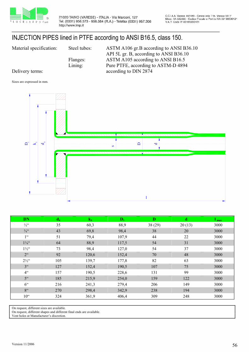
Version 11/2006 56
INJECTION PIPES lined in PTFE according to ANSI B16.5, class 150.
Material specification: Steel tubes: ASTM A106 gr.B according to ANSI B36.10
API 5L gr. B, according to ANSI B36.10
Flanges: ASTM A105 according to ANSI B16.5
Lining: Pure PTFE, according to ASTM-D 4894
Delivery terms: according to DIN 2874
Sizes are expressed in mm.
dDs
411
dkD
l
DN d4 k1 D1 D d l max
½“ 35 60,3 88,9 38 (29) 20 (13) 3000
¾“ 43 69,8 98,4 38 20 3000
1“ 51 79,4 107,9 44 22 3000
1¼“ 64 88,9 117,5 54 31 3000
1½“ 73 98,4 127,0 54 37 3000
2“ 92 120,6 152,4 70 48 3000
2½“ 105 139,7 177,8 82 63 3000
3“ 127 152,4 190,5 107 75 3000
4“ 157 190,5 228,6 131 99 3000
5“ 185 215,9 254,0 159 122 3000
6“ 216 241,3 279,4 206 149 3000
8“ 270 298,4 342,9 238 194 3000
10“ 324 361,9 406,4 309 248 3000
On request, different sizes are available.
On request, different shapes and different final ends are available.
Vent holes at Manufacturer’s discretion.

Version 11/2006 57
PTFE INJECTION NOZZLE (without steel insert).
Material specification: Lining: Pure PTFE, according to ASTM-D 4894
Delivery terms: according to DIN 2874
Sizes are expressed in mm.
d
s
d
l
4 A
max.
DN s dA d4 l max
½“ 3 16 35 3.000
¾“ 3 21 43 3.000
1“ 3 26 51 3.000
1¼“ 3 34 64 3.000
1½“ 3 39 73 3.000
2“ 3 51 92 3.000
2½“ 3,5 69 105 3.000
3“ 4 78 127 3.000
4“ 4,5 103 157 3.000
5“ 4,5 131 185 3.000
6“ 5 154 216 3.000
8“ 6 206 270 3.000
10“ 7 260 324 3.000
12” 7 311 381 3.000

Version 11/2006 58
DIP PIPES according to ANSI B16.5 class 150.
Material Specification: Steel tube: ASTM A106 gr. B according to ANSI B36.10
API 5L gr. B according to ANSI B36.10
Flanges: ASTM A105 according to ANSI B16.5
Lining: Pure PTFE according to ASTM D 4894
Delivery terms: according to DIN 2874
Sizes are expressed in mm.
dkD
Standard length 150 l
dDs
DN1
2DN
ADAPTING RING
411
DN s d4 k1 D1 D d DN2 l max
½“ 3 35 60,3 88,9 38 (29) 20 (13) 3.000
¾“ 3 43 69,8 98,4 38 20 3.000
1“ 3 51 79,4 107,9 44 22 3.000
1¼“ 3 64 88,9 117,5 54 31 3.000
1½“ 3 73 98,4 127,0 54/70 37 3.000
2“ 3 92 120,6 152,4 70 48 3.000
2½“ 3,5 105 139,7 177,8 82 63 3.000
3“ 4 127 152,4 190,5 107 75 3.000
4“ 4,5 157 190,5 228,6 131 99 3.000
5“ 4,5 185 215,9 254,0 159 122 3.000
6“ 5 216 241,3 279,4 206 149 3.000
8“ 6 270 298,4 342,9 238 194 3.000
10“ 7 324 361,9 406,4 309 248
AD
AP
TE
D T
O T
HE
FL
AN
GE
OF
TH
E
RE
AC
TIO
N V
ES
SE
L
3.000
On request, different sizes are available.
on request, special dip pipes (curved, with spraying nozzles,….) are available.
The Manufacturer will decide whether to mount an adapting ring and/or reinforcing tails.

Version 11/2006 59
DOUBLE WALL DIP PIPES according to ANSI B16.5, class 150.
Material specification: Steel tube: ASTM A106 gr. B according to ANSI B36.10
API 5L gr. B according to ANSI B36.10
Flanges: ASTM A105 according to ANSI B16.5
Lining: Pure PTFE according to ASTM D 4894
Delivery terms: according to DIN 2874
Sizes are expressed in mm.
l
dkD d D
DN1
2DN
41
11
Dd
l
41
1 1
D k d
DN1
2DN DOUBLE WALL DIP PIPE
STRENGTHENED SINGLE WALL DIP PIPE
Standard length 150
Standard length 150
DN s d41 k1 D1 D d DN2 l max
¾“ 3 43 69,8 98,4 70 20 3.000
1“ 3 51 79,4 107,9 70 22 3.000
1½“ 3 73 98,4 127,0 82 37 3.000
2“ 3 92 120,6 152,4 107 48 3.000
2½“ 3,5 105 139,7 177,8 107 63 3.000
3“ 4 127 152,4 190,5 131 75 3.000
4“ 4,5 157 190,5 228,6 159 99
Fla
ng
e o
f th
e
reac
tio
n v
esse
l
3.000
On request, different sizes are available.
On request, special dip pipes (curved, with spraying nozzles,….) are available.
The Manufacturer will decide whether to mount an adapting ring and/or reinforcing tails.
On request, double wall dip pipes can be supplied with a heating jacket, with flanged connections or threaded connections.

Version 11/2006 60
EXPANSION JOINTS according to ANSI B16.5 class 150 Material specifications: Flanges: ASTM A105 according to ANSI B16.5
Expansion joints: “TFM”® (product by Dyneon)
Delivery terms: according to DIN 2874 Sizes are expressed in mm.
d
d4
k
lD
n x d2
120°
Remarks: DO NOT remove the limiting stud bolts of the expansion joints.
DN d d4 k n x d2 D l for 2
conv.
l for 3
conv.
l for 4
conv.
l for 5
conv.
l for 6
conv.
l for 7
conv.
l for 8
conv.
½“ 22 35 60 4 x ½“ 89 38 50 62 74 86 98 110
¾“ 22 43 70 4 x ½“ 98 38 50 62 74 86 98 110
1“ 22 51 79 4 x ½“ 108 41 55 69 83 97 111 125
1¼“ 28 64 89 4 x ½“ 117 41 55 69 83 97 111 125
1½“ 33 73 98 4 x ½“ 127 51 65 79 93 107 121 135
2“ 44 92 121 4 x 5/8“ 152 56 70 84 98 112 126 140
2½“ 62 105 140 4 x 5/8“ 178 54 70 86 102 118 134 150
3“ 70 127 152 4 x 5/8“ 190 54 70 86 102 118 134 150
4“ 94 157 190 8 x 5/8“ 229 82 100 118 136 154 172 190
5“ 122 185 216 8 x ¾“ 254 82 100 118 136 154 172 190
6“ 144 216 241 8 x ¾“ 279 87 105 123 141 159 177 195
8“ 194 270 298 8 x ¾“ 343 86 105 124 143 162 181 200
10“ 246 324 362 12 x 7/8“ 406 78 105 132 159 186 n.a. n.a.
12” 297 381 432 12 x 7/8“ 483 78 105 132 159 186 n.a. n.a.
14” 325 413 476 12 x 1” 533 78 105 132 159 186 n.a. n.a.
16” 376 470 540 16 x 1” 597 93 120 147 174 201 n.a. n.a.
18” 420 533 578 16 x 11/8” 635 93 120 147 174 201 n.a. n.a.
20” 471 584 635 20 x 11/8” 698 93 120 147 174 201 n.a. n.a.
24” 595 692 749 20 x 1¼” 813 81 100 n.a. n.a. n.a. n.a. n.a.
n.a. = not available.
Flanges are according to ANSI 150 lbs. All the sizes are provided with threaded holes (passing through). All the expansion joints are moulded in “TFM”® (made by Dyneon), with mechanical properties absolutely superior than the traditional PTFE. The expansion joints are supplied with 3 stud bolts for the limit stop at 120° on diameter: DO NOT REMOVE THE LIMITING STUD BOLTS. Each convolution is provided with a stainless steel reinforcing ring, for better performances. The movement of each convolution is + 12 mm (expansion) / - 8 mm (compression), longitudinally. On request, it is possible to supply expansion joints with stainless steel flanges. Special sizes shall be required to the Manufacturer.

61
Dia
gra
m p
res
su
re -
te
mp
era
ture
fo
r e
xp
an
sio
n j
oin
ts w
ith
2 c
on
vo
luti
on
s
16
16
15,3
14,6
13,9
13,3
12,7
12,2
11,6
11
10,4
9,8
9,3
8,8
8,3
7,9
7,5
7,1
6,8
6,5
6,2
5,9
14,5
14,5
13,8
13,1
12,4
11,8
11,2
10,6
10
9,5
98,6
8,2
7,8
7,5
7,2
6,9
6,6
6,3
65,7
5,4
11,1
11,1
10,5
9,9
9,3
8,8
8,3
7,9
7,5
7,1
6,8
6,5
6,2
5,9
5,7
5,5
5,3
5,1
4,9
4,7
4,6
4,5
88
7,6
7,2
6,8
6,4
6,1
5,8
5,5
5,2
4,9
4,7
4,5
4,3
4,1
3,9
3,7
3,5
3,4
3,3
3,2
3,1
02468
10
12
14
16
18 -1
5°
0°
10°
20°
30°
40°
50°
60°
70°
80°
90°
100°
110°
120°
130°
140°
150°
160°
170°
180°
190°
200°
°C
bar
15÷100 -
½"÷
4"
125-1
50 -
5"-
6"
200-2
50 -
8"-
10"
300÷600 -
12"÷
24"

62
Dia
gra
m p
res
su
re -
te
mp
era
ture
fo
r e
xp
an
sio
n j
oin
ts w
ith
3 c
on
vo
luti
on
s
16
16
15,2
14,4
13,6
12,8
12
11,2
10,6
10
9,4
8,8
8,3
7,8
7,3
6,9
6,5
6,1
5,8
5,5
5,2
4,9
14,1
14,1
13,3
12,5
11,8
11,1
10,5
9,7
9,2
8,7
8,2
7,8
7,4
76,6
6,2
5,8
5,4
5,1
4,8
4,6
4,4
10,7
10,7
10,2
9,6
9
8,4
7,9
7,4
76,6
6,2
5,8
5,5
5,2
54,8
4,6
4,4
4,2
43,8
3,7
7,5
7,5
7
6,5
6,1
5,7
5,3
54,7
4,4
4,1
3,9
3,7
3,5
3,3
3,1
32,9
2,8
2,7
2,6
2,5
02468
10
12
14
16
18 -1
5°
0°
10°
20°
30°
40°
50°
60°
70°
80°
90°
100°
110°
120°
130°
140°
150°
160°
170°
180°
190°
200°
°C
bar
15÷100 -
½"÷
4"
125-1
50 -
5"-
6"
200-2
50 -
8"-
10"
300÷600 -
12"÷
24"

63
Dia
gra
m p
res
su
re -
te
mp
era
ture
fo
r e
xp
an
sio
n j
oin
ts w
ith
4 c
on
vo
luti
on
s
14,2
14,2
13,4
12,6
11,8
11
10,2
9,5
8,8
8,2
7,6
7
6,5
65,6
5,3
54,8
4,6
4,4
4,2
4
11,9
11,9
11,2
10,5
9,9
9,3
8,7
8,1
7,6
7,1
6,6
6,2
5,8
5,4
5,1
4,8
4,6
4,4
4,2
43,8
3,6
99
8,4
7,8
7,3
6,8
6,3
5,9
5,5
5,1
4,7
4,4
4,1
3,8
3,6
3,4
3,2
3,1
32,9
2,8
2,7
6,6
6,6
6,2
5,8
5,4
54,6
4,2
3,9
3,6
3,3
3,1
2,9
2,7
2,5
2,3
2,1
21,9
1,8
1,7
1,6
02468
10
12
14
16 -1
5°
0°
10°
20°
30°
40°
50°
60°
70°
80°
90°
100°
110°
120°
130°
140°
150°
160°
170°
180°
190°
200°
°C
bar
15÷100 -
½"÷
4"
125-1
50 -
5"-
6"
200-2
50 -
8"-
10"
300÷600 -
12"÷
24"

64
Dia
gra
m p
res
su
re -
te
mp
era
ture
fo
r e
xp
an
sio
n j
oin
ts w
ith
5 c
on
vo
luti
on
s
13,5
13,5
12,6
11,8
11
10,2
9,5
8,8
8,2
7,5
6,8
6,2
5,7
5,3
4,9
4,6
4,3
43,8
3,6
3,4
3,3
10
10
10
9,3
8,6
8
7,5
76,6
6,2
5,8
5,4
5,1
4,8
4,5
4,3
43,7
3,5
3,3
3,1
3
88
8
7,4
6,8
6,3
5,8
5,4
54,6
4,3
43,7
3,4
3,1
2,9
2,7
2,5
2,3
2,2
2,1
2
5,8
5,8
5,8
5,3
4,8
4,4
43,7
3,4
3,1
2,9
2,7
2,5
2,3
2,1
1,9
1,7
1,6
1,5
1,4
1,3
1,3
02468
10
12
14
16 -1
5°
0°
10°
20°
30°
40°
50°
60°
70°
80°
90°
100°
110°
120°
130°
140°
150°
160°
170°
180°
190°
200°
°C
bar
15÷100 -
½"÷
4"
125-1
50 -
5"-
6"
200-2
50 -
8"-
10"
300÷600 -
12"÷
24"

65
Dia
gra
m p
res
su
re -
te
mp
era
ture
fo
r e
xp
an
sio
n j
oin
ts w
ith
6 c
on
vo
luti
on
s
9,8
9,8
9,8
9,8
9,1
8,4
7,7
7
6,4
5,8
5,2
4,7
4,2
3,8
3,4
3,1
2,8
2,5
2,3
2,1
22
7,5
7,5
7,5
7,5
6,9
6,3
5,8
5,3
4,8
4,4
43,7
3,4
3,1
2,9
2,7
2,5
2,3
2,1
1,9
1,8
1,8
6,9
6,9
6,9
6,9
6,4
5,9
5,4
4,9
4,5
4,1
3,7
3,3
32,7
2,4
2,1
1,9
1,7
1,5
1,4
1,3
1,3
4,5
4,5
4,5
4,5
4
3,5
3,1
2,7
2,4
2,1
1,8
1,6
1,4
1,3
1,2
1,1
11
11
11
02468
10
12 -1
5°
0°
10°
20°
30°
40°
50°
60°
70°
80°
90°
100°
110°
120°
130°
140°
150°
160°
170°
180°
190°
200°
°C
bar
15÷100 -
½"÷
4"
125-1
50 -
5"-
6"
200-2
50 -
8"-
10"
300÷600 -
12"÷
24"

66
Dia
gra
m p
res
su
re -
te
mp
era
ture
fo
r e
xp
an
sio
n j
oin
ts w
ith
7 c
on
vo
luti
on
s
7,2
7,2
7,2
7,2
7,2
6,7
6,2
5,7
5,2
4,7
4,2
3,7
3,3
2,9
2,5
2,2
1,9
1,6
1,4
1,3
1,3
1,3
6,6
6,6
6,6
6,6
5,9
5,3
4,8
4,3
3,9
3,5
3,2
2,9
2,6
2,3
2,1
1,8
1,6
1,4
1,2
1,1
11
66
66
5,5
5
4,5
4,1
3,7
3,3
3
2,7
2,4
2,1
1,9
1,7
1,5
1,3
1,2
1,1
11
012345678 -15°
0°
10°
20°
30°
40°
50°
60°
70°
80°
90°
100°
110°
120°
130°
140°
150°
160°
170°
180°
190°
200°
°C
bar
15÷100 -
½"÷
4"
125-1
50 -
5"-
6"
200-2
50 -
8"-
10"
300÷600 -
12"÷
24"

67
Dia
gra
m p
res
su
re -
te
mp
era
ture
fo
r e
xp
an
sio
n j
oin
ts w
ith
8 c
on
vo
luti
on
s
66
66
6
5,5
5,1
4,7
4,3
3,9
3,5
3,1
2,7
2,4
2,1
1,8
1,5
1,3
1,1
11
1
66
66
5,5
4,9
4,4
3,9
3,5
3,1
2,8
2,5
2,2
1,9
1,7
1,5
1,3
1,2
1,1
11
1
5,6
5,6
5,6
5,6
5,1
4,6
4,1
3,7
3,3
2,9
2,6
2,3
2,1
1,9
1,7
1,5
1,3
1,2
1,1
11
1
01234567 -15°
0°
10°
20°
30°
40°
50°
60°
70°
80°
90°
100°
110°
120°
130°
140°
150°
160°
170°
180°
190°
200°
°C
bar
15÷100 -
½"÷
4"
125-1
50 -
5"-
6"
200-2
50 -
8"-
10"
300÷600 -
12"÷
24"
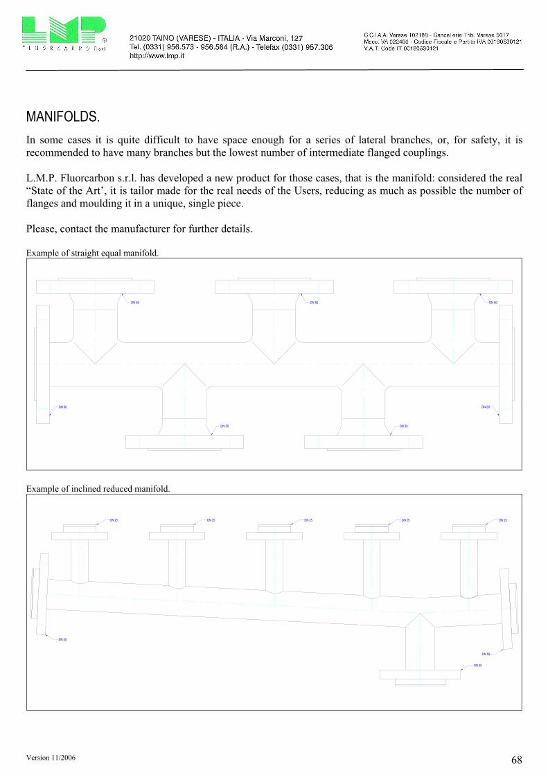
Version 11/2006 68
MANIFOLDS.
In some cases it is quite difficult to have space enough for a series of lateral branches, or, for safety, it is
recommended to have many branches but the lowest number of intermediate flanged couplings.
L.M.P. Fluorcarbon s.r.l. has developed a new product for those cases, that is the manifold: considered the real
“State of the Art’, it is tailor made for the real needs of the Users, reducing as much as possible the number of
flanges and moulding it in a unique, single piece.
Please, contact the manufacturer for further details.
Example of straight equal manifold.
DN 50 DN 50
DN 50 DN 50
DN 50 DN 50 DN 50
Example of inclined reduced manifold.
DN 50
DN 50
DN 25 DN 25 DN 25 DN 25 DN 25
DN 50

Version 11/2006 69
JACKETED PIPES AND FITTINGS.
L.M.P. Fluorcarbon s.r.l. can propose pipes and fittings with heating jackets: both the alternatives ANSI and
DIN are available with heating unit.
Two choices can be offered, the flanged connections or the threaded ones.
Please, contact the manufacturer for further details.
Instrument tapping with heating jacket – version with flanged connections.
SECTION A - A
A A
FLANGED CONNECTION
FOR HEATING JACKET
FLANGED CONNECTION
FOR HEATING JACKET
Instrument tapping with heating jacket – version with threaded connections.
A A
SEZIONE A - A
THREADED CONNECTION FOR HEATING JACKET
THREADED CONNECTION FOR HEATING JACKET

Version 11/2006 70
COLUMNS AND VESSELS.
L.M.P. Fluorcarbon s.r.l. has developed a full range of ptfe lined column sections and vessels with an
innovative system for lateral branches, in order to guarantee a perfect sealing even in case of critical
applications.
The result is a customized column or reaction vessel, designed for the most different applications and made
following very severe building criteria.
Please, contact the manufacturer for further details.
Example of column.
Ø 1
50
Ø 1
60
Ø 1
80
Ø 1
85
Ø 2
13
Ø 2
23
10
2025
5
3083
93
M20
Ø 1
49M
180
pass
o 3
Ø 4
8
Ø 5
5
Ø 7
1
Ø 7
6
1016M
16
18
3,5
25
7376
M71
pass
o 3
Ø 4
8no
ccio
lofil
etta
to
½"
NP
T
6
4
34
33
Ø 3
0
150
150
24 fo
ri pa
ssan
ti Ø
30
su Ø
920
Ø 9
75
4
4
31
34
1000
6
1000400200
2606
200 200
600
31
34
200 15020073127
100 100100
150 150
100
150
4
31
34
150
4
4
31
34
31
34
Øi p
tfe 7
96
Øe
ptfe
- Ø
i acc
iaio
804
Øe
acci
aio
820
spes
sore
ptfe
4
spes
sore
acc
iaio
8
Ø 48,3
2,6
Øi p
tfe 7
96
Øe
ptfe
- Ø
i acc
iaio
804
Øe
acci
aio
820
spes
sore
ptfe
4
spes
sore
acc
iaio
8
Øi a
ccia
io p
er c
amic
ia 8
63
Øe
acci
aio
per
cam
icia
875
spes
sore
acc
iaio
per
cam
icia
6
2021,5
3
Ø 48,3
2,6
Ø 48,3
2,6
Ø 48,3
2,6
550
550
circa 100
550
circ
a Ø
700
circa 37
30°
6
700
550
639
+
0
13N
+ 1
50
12N
+ 8
50
+10
00
11N
+11
56
+10
06
7N9N
+17
56
8N10
N+
1856
+20
06
3N4N
+220
6
+24
06
+26
06
5N6N
1N2N
3° tr
onco
2° tr
onco
1° tr
onco14
665
1466
6
1466
7
1466
8
1466
9
146
7014
671
137
1467
414
675
1467
71N2N
4N5N
8N
10N
11N
12N
13N
men
sole
di s
uppo
rto
Ser
ie I
men
sole
di s
uppo
rto
Ser
ie II
ELE
VA
ZIO
NI
Ø 51
2 2 2 22 2
3
3
3
4 4 55
6
9
7
8
11 10
1315
16
1616
16
1921
59
43 61
44
57
38
37 61
53
55
51
51
52
55
27
27
52 5227
55
52
27
54
62
62
62
63 66
6467
+ 5
00ta
rga
dati
Ø 1
09
Ø 1
03
1921
Example of vessel.
Ø 7
5
Ø 1
09
10
Ø 1
21
16,3
3°
18
R4
9
16
44
6
50
4
31
34
110
6
Ø 1
50
Ø 8
8,9
5,4
9
15
Ø 1
10
15
250
250
411
390
Ø 9
20
321
Ø 9
75
10
20
Ø 2
47
Ø 2
59
Ø 2
80
Ø 1
00
Ø v
etr
o 1
50
Ø 1
58
8 fo
ri fil
etta
ti M
12
su Ø
185
Ø 2
05
M28
0 p
asso
4
Ø 3
20
Ø 3
50
Ø 3
95
Ø 2
86
Ø 3
23
Ø 3
33
31
88
99
3026
37,5
5
6
7
4,5
Ø 1
09
14
Ø 1
9
Ø 1
4
22
13
3
25
0,5
2,7
8
35
20°
Øi p
tfe
796
Øe
ptfe
804
(Ø
i acc
iaio
)
Ø 8
20
Øi c
am
icia
863
Øe
cam
icia
875
2021,5
1050
110
7974
1574
296,5
Ø430
Ø630
Ø796 (interno ptfe)
Ø875 (esterno camicia)
Ø920
Ø97
5
Ø30
100
Ø 2
5
Ø 3
1
Ø 7
0
Ø 7
5
Ø 1
01
Ø 1
09
10
18
M6
2 p
asso
3
Ø 1
10
Ø 1
50
18
47,5
7582,5
45°
4
31
34
6
34
120
130
351
ca. 100
550
550
550
Ø150
Ø11
0Ø85
M12M16
40
44
44
130
140
Ø150
Ø110
M16
Ø75
M12 Ø150
Ø110
M16
Ø88
M16
0°
45°
90°
135
°
225
°
270°
AA
180
°
90°
270
°
Ø 2
5
Ø 7
0
Ø 1
01
Ø 3
1
M6
1 p
asso
3
Ø 1
10
Ø 1
50
23,5
49,5
56,5
Ø150
Ø11
0Ø85
M12M16
200
1N
1N
2N
3N
4N5N
5N
6N
6N
7N
7N
8N
9N
9N 8N
209
86
2098
6
209
87
209
88
209
88
209
89
209
89
SE
ZIO
NE
A -
A (
scal
a 1
: 2)
CC
BB
Ø88
,9
5,49
Ø110
Ø150
Ø180
M16
Ø7
07
500
500
1
1 2 2 3
3
4 4
4
4
5
6
7
7
7
7
88
8 8
9
99
9
99
10
10
10 10
10
10
11
13
14
161
8
18
18
18
20
17
18
20
21
21
22
23
23
23
23
24
24
25
25
1819
26
26
27
28
28
28
28
29
30
31
31
32

Version 11/2006 71
COLUMNS AND VESSELS - OPTIONS.
The inside sections of columns and vessels can usually contain other components, in order to obtain the desired
result from the passage of the media.
L.M.P. Fluorcarbon s.r.l. has developed a wide range of complementary components for apparatus, including
among the others grids, conveyers, spray balls, dip pipes…
Please, contact the manufacturer for further details.
Example of grid.
Example of conveyer.
Example of dip pipe.

Version 11/2006 72
SPECIAL PIECES.
Chemical plants are very often critical due to the missed space to permit modifications, or processes are asking
difficult plants to obtain the desired final results: L.M.P. Fluorcarbon s.r.l. has a chance to study special
components, out of any standardisation, to satisfy the Customers’ needs.
Thanks to our technology of the isostatic moulding process, we have a good flexibility to create “tailor made”
pieces, trying to solve the space troubles and the technical matters faced in a plant.
Please, contact the manufacturer for further details.
Example of special sight glass.
Example of special concentric reducer.
Example of special 90° bend.
Example of special strainer.

Version 11/2006
Via Marconi, 127 21020 TAINO (Varese) - Italy
Phone +39 0331 956.573 Fax +39 0331 957.306
e-mail: [email protected] - http://www.lmp.it