Summary of the Third APEX Meeting
32
3rd APEX Meeting, May 6-8,98 -1- M.Z.Y, June 4, 1998 Summary of the Third APEX Meeting May 6-8, 1998 UCLA Content I. Introduction II. Summary of Working Sessions III. Action Items IV. APEX-Phase I Milestones V. Requirements for a Concept (Analysis Information) VI. Requirements for a Concept (Planning and Comparison Information) VII.Meeting Agenda VIII.List of Attendees IX. Appendices I. Introduction The third APEX meeting was held at UCLA, May 6-8, 1998. A summary of the working sessions, prepared by respective chairmen and the Secretary, is given in Section II. Section III lists the action items agreed upon during the meeting. The milestones of Phase I of the APEX study is given in Section IV. For a concept to be further evaluated within the study, it was agreed that there is minimum information that should be provided about the concept, mainly, the Analysis Information (defined in Table 1, Section V) and Planning and Comparison Information (defined in Table 2, Section VI. The meeting agenda is in given in Section VII and a list of attendees is given in Section VIII. Section IX is reserved for Appendices. The presentations given during the meeting, this summary, and other information can be found on the APEX Web Page http://www.fusion.ucla.edu. II. Summary of Working Sessions Summary of Session I Status and Rational Session Chair: Sam Berk, OFES S. Berk (OFES) presented the current status of the U.S. Fusion Technology Program (USFTP) in relation to the other elements of the Fusion Energy Sciences. The USFTP heavily focused in FY 1998 on ITER-specific tasks. In FY 1999, a transition to broader scope of activities is envisioned (e.g. reduction in ITER-specific tasks but ITER remains the major element of program, increase in effort on enabling technologies for U.S. plasma experiments such as D-DIII, C-MOD, and worldwide plasma experiments such as JT-60, LHD, JET). Emphasis will also be placed on dual purpose tasks that support both ITER and plasma experiments. In addition, the scope will be broadened with innovative technology initiatives where APEX/ALPS studies fall in. The total of $50 M in FY 1999 will be devoted to (a) Advanced Design/Analysis (ITER + Development Path and Power Plant Studies) - 34%, (b) Enabling Technologies (ITER-specific
Transcript of Summary of the Third APEX Meeting

3rd APEX Meeting, May 6-8,98 -1- M.Z.Y, June 4, 1998
Summary of the Third APEX MeetingMay 6-8, 1998
UCLA
Content I. IntroductionII. Summary of Working SessionsIII. Action ItemsIV. APEX-Phase I MilestonesV. Requirements for a Concept (Analysis Information)VI. Requirements for a Concept (Planning and Comparison Information)VII. Meeting AgendaVIII. List of AttendeesIX. Appendices
I. Introduction
The third APEX meeting was held at UCLA, May 6-8, 1998. A summary of the workingsessions, prepared by respective chairmen and the Secretary, is given in Section II. Section IIIlists the action items agreed upon during the meeting. The milestones of Phase I of the APEXstudy is given in Section IV. For a concept to be further evaluated within the study, it was agreedthat there is minimum information that should be provided about the concept, mainly, the AnalysisInformation (defined in Table 1, Section V) and Planning and Comparison Information (defined inTable 2, Section VI. The meeting agenda is in given in Section VII and a list of attendees is givenin Section VIII. Section IX is reserved for Appendices. The presentations given during themeeting, this summary, and other information can be found on the APEX Web Pagehttp://www.fusion.ucla.edu.
II. Summary of Working SessionsSummary of Session I Status and RationalSession Chair: Sam Berk, OFES
S. Berk (OFES) presented the current status of the U.S. Fusion Technology Program (USFTP) inrelation to the other elements of the Fusion Energy Sciences. The USFTP heavily focused in FY1998 on ITER-specific tasks. In FY 1999, a transition to broader scope of activities is envisioned(e.g. reduction in ITER-specific tasks but ITER remains the major element of program, increasein effort on enabling technologies for U.S. plasma experiments such as D-DIII, C-MOD, andworldwide plasma experiments such as JT-60, LHD, JET). Emphasis will also be placed on dualpurpose tasks that support both ITER and plasma experiments. In addition, the scope will bebroadened with innovative technology initiatives where APEX/ALPS studies fall in.The total of $50 M in FY 1999 will be devoted to (a) Advanced Design/Analysis (ITER +Development Path and Power Plant Studies) - 34%, (b) Enabling Technologies (ITER-specific

3rd APEX Meeting, May 6-8,98 -2- M.Z.Y, June 4, 1998
and Dual Purpose + U.S. and Worldwide Plasma Experiments) - 35%, (c) Advanced Materials(Structures and Irradiation Facilities and Non-structural and Systems Interactions) - 15%, (d)Advanced Technologies (Power Handling Innovations + Plasma Support Innovations) - 7%, and(e) Management/Close-out/SBIR - 9%. Berk pointed out that enhanced community role will beemphasized through the Virtual Laboratories that are created in many parts of the U.S. DOE.The USFTP Virtual Laboratory will be fully established by the end of 1998.
M. Abdou (UCLA) gave introductory remarks to serve as the opening/guidance of the APEXmeeting. He emphasized the long-term objective of APEX as the development of a vision for anattractive product with favorable economics, safety, and environmental impact attributes. Theeconomics is the major challenge that requires high-performance plasma and power extractiontechnology, low failure rates and short maintenance time, high power multiplication and efficienthigh temperature energy extraction system for favorable thermal efficiency. Both innovativeconfinement concept initiative in plasma physics and new initiatives in technology are the two-sided coin for this attractive fusion product.
Based on feedback from the community and for self-consistency in the calculations, Abdouindicated that the reference values for the (peak) neutron wall load (NWL) and the surface heat(SHF) have changed for any proposed concept for high power density (HPD) extraction to be 10MW/m2 and 2 MW/m2, respectively. Additional measure of very high potential of NWL = 20MW/m2 and SHF = 4 MW/m2 is encouraged, if feasible. Some of the proposed HPD conceptswhere either abandoned from last meeting (e.g. Heat pipe, Mist flow) or put on hold during thismeeting (Porous Wall). In the later case, recent analysis has indicated that the stress andtemperature limits of SiC, for example, could be exceeded based on the current data under highNWL. The consensus of the attendees (discussed during the last day, see action items) is to holdthe filtrated porous wall concept for the time being. Other concepts that will be pursued are, thethin Convective thin wall concept, the thick liquid wall (free fall and magnetically restrained)concept, the free fall Li2O Particulates with no structural FW concept, and the helium-cooledsolid refractory FW concept. The vaporization concept presented by Malang (FZK) wasencouraged to be evaluated in-depth. Abdou emphasized that proposals for new concepts willalways be welcome throughout the project. Minimum required information about a proposedconcept were discussed in details during the last day of the meeting (See Section IV, V, and VI)
During the session it was agreed that steady state operation in Tokamaks is the reference pointAdvanced Tokamak , ARIES-RS, general parameters will be adopted in the study. Open systemssuch FRC/Spheromak will also be considered as an alternative confinement system. Ralph Moir(LLNL) will (or find a physicist to) get configuration and boundary conditions of such systems.
The two stages of the study till October 2000 were defined by Abdou. Stage 1 is for the designidea formulation in which an idea for the design concept is evolved followed by supportinganalysis to examine the scientific feasibility of the concept. Mechanical design options should alsobe explored and resources be defined to assist in continuing (or terminating) a concept. Thedecision will be based on judgment by Project Management (Steering Committee). AccomplishingStage 2 will be the final product of APEX first 3 years study in which a reasonably detailedanalysis and mechanical design of a concept is outlined in more details and ranking of each

3rd APEX Meeting, May 6-8,98 -3- M.Z.Y, June 4, 1998
concept will be based on expert judgment and qualitative evaluation. Participants agreed that thecompletion of Stage 2 will lead to the start of a full-fledged conceptual design of a reactor basedon the winning concepts that are highly ranked. The APEX Schedule and Milestones in thepresent 3-year study were presented by Abdou and are given in Section IV.
Abdou announced that the next APEX meeting will be held in Albuquerque , New Mexico, July27-28, 1998. Plasma interface issues and plasma confinement concepts will be held July 29, 1998followed by the ALPS meeting, scheduled July 30-31, 1998, in the same place.
The importance of improving plasma performance and the strong tie between plasma physics andHPD technology was emphasized by Kotschenreuther (UTXS). He presented several options forhigh power density plasmas in Tokamaks and in spheromaks/FRC. MHD stability codes werereviewed. As was stressed in Berk’s presentation, strong interaction between plasma innovativeoperational scheme and technology innovations should be maintained during the study.
Announcements and review of last APEX meeting’s action items were given by Youssef (APEXSecretary, UCLA) as the last presentation in this session (see Appendix I).
Summary of Session II: Analysis of Promising HPD Concepts for APEXSession Chairmen: Neil Morley and Mahmoud Youssef, UCLA
This was a long session, which took most of Wednesday and part of Thursday, where analyses onpreviously proposed high power density concepts, and ideas for some new concepts, werereported. One idea that came out of the session was the fact that concepts that tolerate leaks orsoft failures, would be very advantage. Also, concepts that radically reduce the primary stress andneutron damage may result in longer lifetime of components and less hard failure, reducing theneed for costly and time consuming blanket replacements. The following summary is organizedaccording to design concept.
Convective Liquid LayerN. Morley (UCLA) gave a presentation looking at the power balance, hydraulics and vacuumdrainage of the thin, fast liquid layer concept with integrated droplet divertor. The issues wereexplored for both lithium and flibe as working liquid. The following conclusions were made.
(1) A 2 cm thickness turbulent flibe flow at 10 m/s is needed to ensure wall adhesion, while thesurface temperature rise should be small due to turbulent mixing. A 2 cm thick laminar-MHDlithium flow at 20 m/s is required to keep the surface temperature rise below 100 K.
(2) At these flow rates the overall bulk temperature rise is ~100 K if the entire flow is recirculatedto the blanket region. It is desirable to reduce the flow rates to increase the bulk temperature rise,but the amount of any reduction is limited by (1).
(3) Drain from vacuum of lithium at these flow rates may require long, large pipes due to MHDforces. Flibe drainage by gravity is not seen to be a problem.
3rd APEX Meeting, May 6-8,98 -4- M.Z.Y, June 4, 1998
More detailed calculations are need to really optimize the flow rates in conjunction with otherconcerns like drainage and bulk temperature rise. The group expressed concerns that thecompeting goals of low surface temperature and high exit temperatures may make lithium difficultto apply. The question was raised as to what are the real difficulties with flibe. D.K. Szesuggested that fast flowing flibe might be decomposed by the V x B EMF generated in the semi-conductor.
A. Hadid (Boeing) presented some discussion of different techniques for free surface computationand reviewed Rocketdyne’s capabilities in this area. He is working with UCLA to analyze boththick and thin liquid flows.
Thick Liquid WallsA. Ying (UCLA) presented 2D Navier-Stokes solutions where she shows that free thick liquid jetstend to be dramatically thinned due to the acceleration of gravity. This can be overcome byincreasing the velocity of the jets, but then the recirculation power is increased while the bulktemperature rise is decreased. Ideas to combat this thinning were discussed including somestructure at the rear of the flow which would tend to slow down the flow and maintain thethickness. Also considered are multiple layer slabs, starting at different vertical heights.
M. Youssef (UCLA) presented the level of radiation damage in the vacuum vessel for the flowingliquid FW concept. In this concept, the thick liquid layer is assumed to be flowing poloidally onthe surface of the V.V. whereas the blanket is outside the vacuum boundary behind the V.V.Material combination considered for the liquid wall/blanket are Li/(Li-V4Cr4Ti,80:20) andFlibe/(Flibe-FS,80:20). Because neutron mean free path (MFP) in Li at energies above ~3eV islarger than those in Flibe by as much as an order of magnitude, the damage to the V.V.(expressed in terms of DPA, he-4, and H production rate) as a function of the flowing layerthickness is noticeably larger than in the Flibe case. Consequently, the 10-fold thickness of theFlibe (the thickness needed to reduce a damage index by an order of magnitude) was shown to be~25-40 cm while it is about twice as much (~54-80 cm) in the Li case The ratio of the he-4/dparate for a bare wall is ~11 in the Li system and ~3 in the Flibe system and drops to ~6 and 1.5 at alayer thickness of 50 cm. It was argued that ratios similar to those found in fission reactors can inprinciple be achieved by increasing the liquid layer thickness and introducing an appropriateshield. In another presentation given by Youssef, he showed that increasing Li-6 enrichment up to90% could reduce the DPA rate in the V.V. by only ~15% in the 50 cm-thick Flibe case while theimpact is larger (~45% reduction) in the Li case for the same layer thickness. Power multiplicationdecreased in the Flibe case (M=1.13 to M=1.1) and increased in the Li case (M=1.18 to M=1.19).About 30% of the power is deposited in the first 10 cm of the Li layer whereas ~ 45% isdeposited in the Flibe layer for natural Li-6 enrichment
In relation to the above, M. Sawan (UW) presented neutronics results for liquid metal protectedICF chamber and extrapolation to thick liquid metal concept. The results presented were basedon the several ICF chamber designs (HIBALL, HYLIFE, LIBRA-LiTE, LIBRA-SP) performed inthe past decade. The chamber in these designs is protected by a blanket made of flexible INPORT(Inhibited flow PORus Tubes) tubes in which Li17Pb83 (HIBALL) or (Li or Li13Pb83 (LIBRA-LiTE) flows. The structure in these tubes is SiC (HIBALL) or HT-9 (LIBRA-LiTE) with a ratio

3rd APEX Meeting, May 6-8,98 -5- M.Z.Y, June 4, 1998
of 2% (the .packing factor of the tubes is 33%). The variation of chamber structure dpa and he-4production with liquid metal protection thickness was used to determine the e-fold and 10-folddistance for Li, Li17Pb83, and Flibe. It was shown that the 10-fold thickness of Li, LiPb, andFlibe is ~ 52 cm, 45 cm, and 31 cm for dpa response with natural lithium. The correspondingthickness for he-4 response is 43 cm, 20 cm, and 30 cm. Thinner thickness (by ~ 6 cm for dpa and~ 2 cm for he-4) is required if Li-6 is enriched to 90%. These 10-fold thickness’ are very similarto the values presented by Youssef when the second order corrections due to geometrical andspectral differences in ICF and MCF systems are taken into consideration.
Khater (UW) presented the specific activity and decay heat in the FW/V.V. after 30 FPYoperation and 7 MW/m2 wall load in the three Liquid metal/structure options discussed byYoussef, mainly, Li/(Li-V4Cr4Ti), Flibe/(Flibe-FS), and LiPb/(LiPb-SiC.). A comparison ofresults was shown for the three cases: bare FW, natural Li in the 50 cm-thick liquid layer, and90%Li-6 enriched layer. It was shown that using a flowing layer of Li results in a factor of threereduction in the activity and decay heat in the vanadium structure of the FW/V.V. and a further anorder of magnitude reduction is obtained with enriched Li. These reduction factors of layerinclusion are more than an order of magnitude in the Flibe/(Flibe-FS) and the LiPb/(LiPb-SiC)system, respectively. It was also shown that the Flibe/FS option provide the TFC with the highestshielding protection. If Fetter waste disposal are used, the inclusion of the flowing layer will allowfor the disposal of the FW and blanket structure of the three options as low level waste (LLW).However, if the limits of the NRC are applied, the Li/V option is the only one among the threeoptions that is qualified as LLW. Khater showed also that the off-site dose inventory issignificantly reduced when the flowing layer is used to protect the FW/blanket. The LiPb/SiCoption produced the least off-site dose inventory.
Liquid-Infiltrated Porous WallsThe idea to use porous walls with infiltrated liquid to create a compliant, high thermalconductivity first wall was put on hold. N. Ghoniem (UCLA) presented some calculations (by A.El-Azab, UCLA) that showed that the SiC-Li system could not meet the NWL requirements ofAPEX due to decreasing strength of the porous material, and the SiC-Li computabilitytemperature limit of ~600 C. The V-Li system also failed to reach the APEX goals for NWL,being limited by the reduced strength of the V alloy. The group raised questions regarding thedefinition of strength and failure in a porous material. Ralph Moir urged the group to rememberthe concept of “soft-failure” in a leaky wall system is an important goal, since small cracks do notshut down reactor operation. The idea of using a porous wall, or flexible woven wall, should stillbe considered for modified concepts of this type as long as the heat is removed in some cleverway (e.g. evaporation) that doesn’t rely solely on conduction through a thick (~4 mm) wall.
Li2O Particulate FW/Blanket – APPLED.K. Sze (ANL) reviewed the merits and issues associated with the APPLE concept. Hepresented results of calculations in the following areas.
(1) Tritium in the form of tritiated water molecules will diffuse out of the Particulates in about100 s after their birth. About 500 g of tritium will be bred each FPD, releasing 2.5 kg of oxygenas well from the Li2O.
3rd APEX Meeting, May 6-8,98 -6- M.Z.Y, June 4, 1998
(2) The amount of evaporated material released to the plasma was estimated to be 86 kg/FPD,along with an additional 2.5 kg of oxygen (discussed above). Sputtering was estimated to be ofthe same order as Be. The total release of this magnitude requires a plasma edge barrier of ~100to keep core impurities reasonable.
(3) The heat transfer area in the vacuum heat exchanger was estimated to be 30,000 m2, which isconsidered reasonable by current standards. There was some debate by the group whether or notthe heat transfer was computed in a realistic way. The assumption that every particulate comesinto intimate contact with a fin during the passage through the heat exchanger is implicit in thecalculation which determines the required surface area. During that contact time, the particulatecools by radiating to the fin.
The group also expressed concerns over the performance and reliability of the radiation cooledbaffles necessary to direct the flow of Particulates in the FW.
M. Sawan presented also the neutronics, shielding, and activation analyses for the Li2Oparticulate concept discussed in this session by Sze. An overall TBR>1.2 is achievable in thisconcept. A minimum blanket thickness of 40 cm is required for the structure to be a life-timecomponent. However, if rewelding of the V.V. is allowed, the required totalblanket/reflector/shield thickness is ~105 cm. It was shown that more than an order of magnitudereduction in decay heat and short term activity is obtained from placing the structure behind theLi2O particulate blanket. Also, using the low activation ferritic steel (ORNL LAFS 9Cr-2WVTa)as permanent structure behind the Li2O particulate blanket can allow for near surface burial of thewaste.
Helium Cooled Refractory FWC. Wong (GA) reviewed again the requirements of FW/Blanket systems and the benefits of Hecooled liquid breeder blankets. R. Nygren (SNL) reviewed high heat flux testing needs, and theresults of previous solid wall, high heat flux tests at Sandia. The group commented that the stateof understanding of conventional solid wall designs is already considerably more advanced thanthat of radical liquid or flow solid particulate FWs discussed above. Specific calculations anddesign data on this concept was promised for the next meeting in ABQ.
Evaporative Spray Cooling of the FWS. Malang (FZK) proposed a new concept based on the previously (see October meeting)advanced ideas of quasi-heat pipe FW and entrained mist cooling of the FW. Malang’s ideaimproves on these concepts by forcing complete liquid coverage of the FW area by pressurizedliquid jets emanating from a delivery tube. The liquid (sodium, lithium or potassium) thenvaporizes and flows under its own pressure out of the blanket. The concept is inherently hightemperature and requires a refractory metal structure. However, high heat conversion efficiencycan be achieved. In addition, low first wall pressure reduce the worry concerning creep rupture(allowing thinner structural walls) and low liquid coolant velocities eliminates the need forelectrical insulator coatings. M. Tillack (UCSD), N. Morley and R. Mattas (ANL) and B. Nelson(ORNL) volunteered to investigate this concept further.

3rd APEX Meeting, May 6-8,98 -7- M.Z.Y, June 4, 1998
Summary of Session III: Mechanical Design, Configuration, Reliability, and First WallConsiderations (Session Co-chairs: S. Malang, B. Nelson)The purpose of this session was to summarize some of the mechanical design issues associatedwith the APEX blanket and first wall and present the status of design work to date. Thepresentation included discussions of the following topics:
• Status of activities for mechanical design and availability group• General Design Requirements and concept information needed• First thoughts on flowing liquid concept
Status of activities for mechanical design and availability group The Mechanical Design andAvailability Group will assist all design conceptualization groups with the mechanical design andintegration of their concept. Specifically, the group has responsibility for:
1. Vacuum boundary concept2. Mechanical configuration3. Maintenance approach (innovative ideas to enhance maintainability)4. Reliability (suggestions for reducing failure rates and for fault-tolerant designs)5. Minimum wall thickness6. Fabrication techniques
The group includes Brad Nelson, Paul Goranson, Paul Fogarty, John Haines, Dave Lousteau(ORNL); Mark Tillack (UCSD); Siegfried Malang (FZK); M. Dagher, Alice Ying (UCLA); DonClemens (Rocketdyne); Igor Sviatoslovsky (UW);
The group is still in the formative stages, and work since the last meeting has been somewhatlimited. It was suggested at the January APEX meeting that the ARIES RS serve as a baselineconfiguration for incorporating the various APEX concepts, so the ARIES RS design wasreviewed and CAD files were generated for use with the concept development. Additional CADfiles in the PRO-E format were obtained from the ARIES RS group
The general approach for the mechanical design group will be to:1. Develop requirements, both general and concept-specific2. Identify generic device configurations (such as advanced tokamak, ST, etc) to use in the
development of concepts3. Produce a strawman design for each concept, including a 3-D layout showing the main
features of the concept
The group thought that in addition to an advanced tokamak (ARIES RS), an FRC configuration(to be furnished by Ralph Moir) should be included in the study. The ST was judged to be similarenough to the advanced tokamak that separate studies were not required at this time.
General Design Requirements and Considerations

3rd APEX Meeting, May 6-8,98 -8- M.Z.Y, June 4, 1998
A list of general design requirements was presented again as shown in Table 1, but with changesand comments included from the January meeting. Dr. Abdou suggested that the peak powerloading should be increased from 7 to 10 MW/m^2 and the surface heat flux should be increasedfrom 1.5 to 2 MW/m^2. The group decided that the configuration of penetrations for heatingand diagnostics is not known, so a generic 1 m^2 opening should be developed for each concept.It was also noted that the tritium breeding ratio should be 1.3 based on 1-D calculations and 1.2based on more complex calculations.
General Design Requirements and Assumptions
Function Requirement Value/Goal
Power Extraction Neutron Wall Load
Surface Heat Flux
7 MW/m^2 avg*10 MW/m^2 peak*
2 MW/m^2*
Tritium Breeding Self Sufficient TBR > 1.2(1.3 for 1-D)
Shielding Radiation exposure of coils (insulation)Nuclear heating of coils (sc cable)Reweldable confinement boundary
< 1x10⁹ Rad< 1kW/m3
< 1 appm He
Vacuum Compatible with plasma- Base partial pressure, non-fuel- Base pressure, fuel (H,D,T)
< 1x10⁻⁹ Torr< 1x10⁻⁷ Torr
Safetyconfinement boundaries 2
Plasma Exhaust Divertor required to remove helium
Penetrations Plasma Heating Power Density - NBI - ICH
DiagnosticsPenetration size
TBD MW/m2
TBD MW/ m2
TBD1 m^2
OperatingParameters
Pulse LengthNumber of pulsesDisruptions
Steady State> 3,000TBD
Availability Maximize total availability Aplant > .75Ablanket/FW > .98
3rd APEX Meeting, May 6-8,98 -9- M.Z.Y, June 4, 1998
* Values are minimum goals for steady state operation
As was presented in the January meeting, in order to begin the task of assisting with themechanical design for specific concepts, some information is needed by the design group. Thisinformation includes:
• Device type- Point design device (tokamak, stellarator, RFP, etc.)- Limitations (will only work for _____ )
• Configuration- General - 1 m^2 chunk of the FW/blanket- Integrated - schematic of system for point design device (e.g., tokamak)
• Size/total power:- Point design - GW fusion power for developed concept- Limits, if any, on maximum/minimum size/power
• Shielding:- power deposition profile- thickness required for breeding- thickness required to limit coil heating/insulator damage
• Coolant parameters:- cooling media (lithium, flibe, helium, solid, combination)
- flow rate per unit FW area or unit power- inlet and outlet temperatures- inlet and outlet pressure and pumping method
First thoughts on Flowing Liquid conceptInvestigations of the flowing liquid concept have begun, with an attempt to illustrate the locationand available space for the various concept features. These features include:
• Film forming device• Film collecting device• Concept for starting system• Concept for providing heating and diagnostic penetrations• Vacuum pumping concept• Divertor concept
It was apparent that a double null divertor concept would be difficult for this concept, so a singlenull configuration was assumed. The liquid is introduced at the top of the machine, split intomultiple streams by the “film former”, flows down the walls and out the bottom of the torusthrough the vacuum pumping duct to a separator and pump. The liquid does not fill the duct, sothere is not a limit on duct length to provide sufficient head for gravity flow. Penetrations are
3rd APEX Meeting, May 6-8,98 -10- M.Z.Y, June 4, 1998
provided by placing a deflector in the stream on the outboard side. Some of the issues for thisconcept include:
• How do you move ~105 kg/s of Li in and out of the machine?• How do you separate the thin and thick flow regimes?• How do you start the two streams?• Does stream follow field lines and come off of the inboard wall?• How do the passive stability currents move the surfaces around?• How do you accommodate a double null configuration?• What are the failure modes?
A meeting at UCLA is proposed for the week of June 15 or June 22 to further develop thisconcept.
Summary of Session IV: Materials Data base and Limits(Chairman: Richard Nygren)
There were six presentations in the Materials Data Base and Limits Session. The first twoscheduled presentations, “Neutron Wall Load Limits for Some Refractory Materials” (El-Azab)and “Assessment of High Temperature Refractory Metals” (Ghoniem) were presented by NasrGhoniem. Two NWL limits, one based on stress and the other on temperature, were shown forTZM, Nb-1Zr and T111 assuming a primary stress of 20 MPa, expansion but not bending, bulkheating of 10 W/cm3 per MW/m2 neutron wall load and a heat flux of 0.2 MW/m2. Acompendium of physical and mechanical properties of Nb and Nb alloys, Mo and Mo alloys, Taand Ta alloys, W and W alloys and Re and Re alloys, and Ni bearing alloys were presented alongwith some data on cost and compatibility with Li and interstitial elements. The followingcomments were offered. The values used for costs of several of the materials appeared to beinaccurate and much too high (several). The DBTT values may be from reduction of areameasurements rather than from Charpy tests (Zinkle). From the standpoint of compatibility withHe coolant, the Mo alloys appear to be the best choice (Ghoniem/Zinkle). Corrosion will notlimit austenitic SS’s at ~600°C (Moir per Devan of ORNL). Transmutation of Ta will lead tomuch higher W content as the alloy is subjected to irradiation, e.g., W increased from 8% to 25%at end of life in STARFIRE (Mattas).
In “Chemical Compatibility and Radiation Effects Issues in High Temperature Refractory Metals”(Zinkle/Ghoniem), recent activities of the APEX Material Group were summarized. Assessmentsof irradiated and unirradiated properties of low activation structural materials (V-4Cr-4Ti, Fe-8Crand SiC/SiC) were completed. Information on oxide dispersion strengthened ferritic andmartensitic steels is being compiled. A draft report on Ta-111 (Ta-8W-2Hf) has been completed.Information on chemical compatibility of refractory alloys with liquid metals is being compiled;and a limited database on radiation effects on refractory alloys has been assembled. The followingcomments were offered. Look at Nb-1Zr in range of 700-1000°C (Ghoniem). Look at Al2O3coating on Ta (Wong). MRS Symposium a couple of years ago may be helpful resource (Zinkle);but now there are new bonding techniques available (Ghoniem). Devan (ORNL) recommends304SS with flibe (Moir). We should raise the temperature limit of interest for flibe from 650°C

3rd APEX Meeting, May 6-8,98 -11- M.Z.Y, June 4, 1998
max. to 1000°C (Sze); this action was accepted. Look at total ductility and reduction of area(Mattas). At these high temperatures, tritium will diffuse everywhere (Sze).
In “Impact of Ferromagnetism of Materials on Fusion Reactors Design” (Zinkle/Tillack)presented by Brad Nelson, the main message was that, while there is no absolute ban on use offerromagnetic materials, there has long been a general concern on their use because of error fieldsduring alignment of the coils and field perturbations during operation. Some analytical workdisputes the validity of these concerns. Also, the forces on primary structures on piping is aconcern and was evaluated in STARFIRE and MARS. The following comments were offered.There are some good but old calculations but few people have looked in detail (Abdou).Physicists are taught to avoid field errors; we need to make calculations for real designs (Meade).
“Risks from Low Activation Materials” (Kotschenreuther) was an overview of concerns regardingactivation associated with fusion reactors. The following comments were offered. The EZCOManalysis presents some real problems now since we know more now but this analysis is wellpublicized and referenced (McCarthy). We must be careful not to overstate what “low activation”means (Abdou).
In “An Overview of Safety and Environmental Issues for APEX” (McCarthy), safety goals forfusion and lessons learned were reviewed. Among the many lesson, issues and concerns reviewedwas the recommendation that stopping neutrons in a small volume, even if it means generatingsome greater-than-Class-C waste, is preferable to spreading neutrons out through a very largevolume. The scope and depth of the ITER EDA safety effort was unprecedented and provides avaluable resource. In the discussion, Kathy McCarthy noted that Japan is formulating disposalguidelines for fusion and looking at (a) reuse, (b) low level and (c) medium level (but not highlevel). The issue of W mobilization was raised; Kathy intends to do a parametric study. Anaction item was reported; 20 experiments were done at the University of Wisconsin in which Li at527°C was introduced into Therminal 66 (organic coolant) at 300°C. There was no real reactionat 300°C and maybe a very slow reaction below 300°C and some decomposition of Therminal at400°C.
Summary of Session V: Physics Interface(Chairman, Dale Meade , PPPL)
Mattas (ANL) gave the latest activities in the ALPS project, particularly the summary of lastFebruary 1998 meeting, in the area of physics and engineering. In the physics area, he showed thatliquid surfaces (e.g. Li) will significantly affect the plasma edge and core performance byincreasing confinement, enhancing DT fusion power and radiation losses (by as much as 100%increase) with high-z impurities. Little or no penetration into plasma core by Li is envisioned withminimal effect on electron temperature. There is unresolved (not understood) phenomenon thatwas observed from experiment. Instead of plasma cooling in response to the additional radiativepower losses due to impurity injection, the electron temperature stayed approximately the samewhile total stored plasma energy increased. Similar results were observed on other Tokamaks(e.g. ISX (ZMODE), TEXTOR (RIMODE)). Topics discussed by Mattas in the physics areawere:

3rd APEX Meeting, May 6-8,98 -12- M.Z.Y, June 4, 1998
(a) Plasma-Materials Interactions: Li will trap essentially all DT particles striking the surface aspredicted by the DIFFUSE model (SNL) - He may be trapped - there could be enhancedsputtering of liquid surfaces due to bubble/droplet formation (SPLASH code).
(b) PMI Experiments: DiMES can be used to test ALPS concept (SNL) - PISCES can offer anexperimental verification of liquid metal droplet iteraction in plasmas - The SNL facility can beused to test sputtering of liquid and surface segregation effects while the UIUC facility can beused to study sputtering of solid Li.
In the engineering areas, Mattas discussed the ALPS basic issues on what limits heat removal inliquid surface PFCs. This complex question involves disciplines such as heat transfer, thermalhydraulics and surface stability. Liquid metal film flow in magnetic field is also a complex problemsince many factors come together to influence heat transfer at the free surface, and all requiremodeling to assess their relative importance (i.e. unsteady, 3D, free surface, turbulent, MHD flowanalysis is required). This applies as well to liquid metal droplet flows in magnetic field. Livaporization rate from surfaces is another issue discussed. As for the next steps, suggestedscreening criteria were outlined for the ALPS study. This includes peak/average heat flux in thedivertor of 5/2, useful heat thermal efficiency > 20%, safety (tritium inventory < 500 g -use ofreduced activation materials), component should withstand neutron fluence > 10 MW-yr/m2 andlifetime-erosion > 2 MW-yr/m2. The concept evaluation will be based on performance in severalareas such as plasma scrape-off & core specifications, surface sciences (e.g. sputtering, DT/Hetrapping/release), heat transfer characteristics (e.g. thermal response, MHD free-surface flow), X-vessel components behavior (e.g. tritium system, heat exchanger), safety (e.g. accident response,waste disposal issue, recycling), and foundation of the data base (e.g. surface properties, solid andliquid bulk properties).
Plasma operation and interface issues were next discussed by Meade (PPPL). These issues wereraised during last APEX meeting and were addressed by this time. As for the liquid surfaceplasma interface, Meade showed that, based on typical scrape-off parameters of TFTR andARIES (ne ~ 1013 cm-3, Te > 10 eV, width wes ~ 10 cm) and Li surface parameters ( SHF ~1.5MW/m2, Tsurface ~ 500 °C), the idealized screening estimate is more than adequate. This isconsistent with the TFTR Li injection experience where ~< 0.1% Li penetration occurred for 25MW beam heating. As for the question of whether or not the high influx of wall impurities willquench the screening action of the plasma scrape-off, he showed that this issue “looks OK” andshould not raise a concern (power input to scrape-off plasma from core ~ 200 MW and powerloss from scrape-off due to ionization and radiation ~ 30 MW, using ARIES-RS parameters).Meade indicated that present codes to model the plasma scrape-off of Tokamaks (e.g. EIRENE +B2.5, UEDGE + DEGAS2) could in principle be modified to model the problems at hand in theAPEX study to address the screening and dynamics of the scrape-off for liquid walls. He alsoaddressed the merits/disadvantages of rectangular FW as opposed to FW that follow the contoursof plasma edge.
Other presentations in this session were given by Kotschenreuther (Reducing Liquid Wall SurfaceTemperature with Plasma Instability) and Moir (Edge Plasma calculations). In the first

3rd APEX Meeting, May 6-8,98 -13- M.Z.Y, June 4, 1998
presentation, Kotschenreuther indicated that sources of plasma turbulence are important for liquidwalls since they could lead to reducing surface temperature and may cause splashing into plasma.Rippling mode is identified as the most important instability for plasma. It is the resistive MHDinstability which produces the most turbulence and heat transport. He pointed out that thedifferences of the liquid walls from plasma case are in the boundary conditions and that surfacetension effect should be included in modeling the liquid FW. In the latter presentation, Moiraddressed the same issue discussed by Meade, emphasizing the need for plasma modeling usingcodes such as UEDGE and DEGAS to estimate how much evaporated liquid materials willpenetrate through the edge plasma. He showed rough calculations (most of the parameters usedneed to be checked) for the evaporation rates in Tokamak and Field Revered Configuration (FRCor Spheromak). Moir presented also some chemical kinetics for Flibe. He concluded byaddressing the need for cross section information on D, T, He, Li, BeF2, LiF and UEDGEcalculations for open and closed field line edge plasmas. He further emphasized the couplingbetween plasma physics and blanket technology by addressing the need to examine for eachconfinement concept whether or not a thick liquid layer could replace the usual solid FW.
Summary of Session VI: Parallel Group Meetings
The seven groups of APEX study met in the afternoon of Thursday to discuss key feasibilityissues pertaining to the scope of each group. These groups are: Evaluation Criteria, Materials,Mechanical Design and Availability, Plasma Interface and Alternate Confinement, PowerConversion, , Safety and Environment, and the Neutronics Group (the latter three groups havebeen globally termed as the Analysis Group). Reports from these groups were scheduled forpresentation Friday morning.
Summary of Session VII: Group Reporting(Chair: M. Abdou)
The lead person of each group presented a summary of the key issues/action items in his/hergroup. Summary of reports are given below for some groups:
Materials Group (Zinkle): (1) Prepare summary on liquid metal compatibility (Li, Pb-Li, Flibe) with structural materials(F/M steels, V alloys, SiC/SiC, Ta, 300SS, Nb, Mo, W).(2) Prepare a summary on He coolant compatibility.(3) Complete property assessment reports on Ta, Mo, W alloys.(4) Prepare mechanical design report (modification of ITER documentation).(5) Porous materiel properties: general analysis completed by El-Azab, Further reports are put onhold.(6) Other issues: tritium permeation, impact of insulating coatings (T2 permeation, etc.), joiningtechniques (friction welding, etc.), updating cost of materials (7/98), and transmutation effects(through the neutronics group)
Power Conversion Group (Sze) (1) Don’t use binary cycle. Using regenerator HX is always beneficial.

3rd APEX Meeting, May 6-8,98 -14- M.Z.Y, June 4, 1998
(2) Keep the coolant exit temperature as high as possible.(3) Keep the coolant ∆T in the range of 200 to 400 °C, if possible.(4) Keep the coolant inlet temperature > 300 °C.(5) The group will work with all blanket concepts to develop the power conversion system as thecoolant parameters are defined.
Tritium Issues (Sze) (1)FW tritium permeation.(2) Tritium concentration in structure materials.(3) Tritium clean-up, recovery and processing.(4) Tritium Safety.(5) Fueling and vacuum.
Neutronics Group (Youssef) (1) Attenuation characteristics of liquid FW and (solids, e.g. SiC) to surface wall load(Bremsstrahlung and cyclotron radiation). Impact of impurities in plasma.(2) Heat deposition profiles in LM/solid FW and blanket from neutrons(3) System power multiplication and percentage of heat deposited in each component.(4) Tritium breeding ratio (TBR) and tritium production profiles (TPR). Percentage of T bred ineach component.(5) Radiation damage to structural materials : in FW, blanket, TFC, etc(6) Impact of Li-6 enrichment on TBR, TPR, and damage parameters.(6) Shielding design(7) Transmutation effect and radioactivity inventory.(8) Decay heat assessment.
Summary of Session VII: Resources, Man Power Requirements, and Technical Plans for DesignConcept Development and Analysis(Chair: M. Abdou)
Each concept proponent presented a plan for the concept during the next 12 Month. Summary foreach concept is given below. More details can be found on the APEX web site:
Thick Liquid Wall Concepts (A. Ying)key tasks next 12 months:(1) Hydrodynamics (free surface flow characteristics and stability
- 1 man (75% from UCLA) on behavior of turbulent liquid jets and films- 1 man (50% UCLA, 50% Boeing) on behavior of electrically conducting liquid jets- 0.5 man (UCLA) on liquid jet stability
(2) Heat Transfer- 0.5 man (30% UCLA) on temperature profiles in liquid jets and film-0.5 man (50% UCLA) on identification and characterization of effect of turbulence.
(3) Design and Engineering Configuration (0.5 man)(4) Supporting analysis
- 0.1 man (neutronics)
3rd APEX Meeting, May 6-8,98 -15- M.Z.Y, June 4, 1998
- 0.1 man (power conversion)- 0.1 (man materials)
Convective Liquid Layer Concept (N. Morley)Analysis needed:(1) Estimates of allowable FW contamination fluff or LMs and Flibe.(2) Detailed analysis of film flow behavior including: wall adhesion, film thickness/velocity, waveformation, heat transfer at surface, and evaporation flux from surface.(3) Analysis of film extraction from vacuum chamber, including possibility of integrated divertor.(4) Estimates of effects of 3D magnetic field (surface T gradient), temporally and spatially varyingmagnetic fields, off-normal plasma events.(5) Thermal hydraulic analysis of system, including feed lines and nozzle, free surface flow,removal from vacuum chamber, recirculation through the blanket, and heat exchanger.(6) Neutronics analysis with consistent mechanical design. (Some overlapping analysis with other LM concepts and with ALPS)Resources2 man-yr (UCLA) for RIPPLE, MHD tool, thermal hydraulics, neutronics).0.5 man-yr (Boeing) for MHD tool0.25 man-yr (ORNL) for mechanical design0.75 man-yr (ANL/LLNL/PPPL) for disruption and plasma edge modeling(Total of 3.5 man-yr, about 1.5 man-yr is considered as overlap with other APEX concepts andALPS)
He-cooled FW/B/Divertor Concept (C. Wong/R. Nygren)Plan was set from date till Feb. 99. By end of FY98, good idea on how the FW/B/Divertorconcept should look and ready to initiate fabrication, reliability, safety, and testing tasks. Tasksfall in the area of evaluation, design/analysis, physics interface, neutronics, safety, fabrication,testing, and compatibility/cleanup/He purification. Design/analysis includes configuration,structural analysis, thermal hydraulics, and stability. Man power requirements are 2 FTE (fromGA), 1 FTE +$150 k experiment (from SNL), 0.1-0.2 FTE (from UCLA for neutronics). Supportfrom INEEL (safety) and ORNL (design) is from Task Accounting (TA).
Plans for other concepts will be submitted to APEX management by June 15 (see action items)
Summary of concluding Round-the-Table-Discussion:
In concluding the workshop, a round-the-table discussion was conducted about the importantpoints of concerns raised during the meeting. They are:
(a) Concept evaluation process: The evaluation criteria group is in the process of developingmeaningful criteria that emphasize scientific foundations and concept potential for majorimprovements. Emphasis is on high power density capability, low failure rate, simplicity, anddesign margin. These criteria are in addition to the usual attributes of economics, safety , andenvironmental impact. R&D requirements is also an important category. New concepts/ideas willalways be welcome. More details on the evaluation process will be discussed in the next meeting.

3rd APEX Meeting, May 6-8,98 -16- M.Z.Y, June 4, 1998
(b) Concepts present at hand and requirements per concept: Three/four classes of concepts areconsidered (Porous Walls concept is put on hold). For each concept there are several issues thatrequire should be resolved. The classes of concepts are: (1) Thin and Thick Liquid FW(controlling the trajectory of the liquid is an issue. In the free falling layer, how to get the liquidbeing formed is an issue), (2) Free falling Li2O Particulates with no solid FW (radiation cooledbaffles to direct Li2O Particulates flow and the amount of material evaporation to plasma areconcerns), (3) Helium-cooled refractory structural FW and (4) Spray coating FW (who isinterested in carrying the evaluation of this concept was tentatively identified after the meeting,namely Malang, Mattas, Tillack, Morley, Wong, Youssef).
Each concept should be presented with supporting analytical results (i.e. each concept should bebrought to the same level of analysis to be able to screen among concepts). There was adiscussion on what is the minimum information required for each concept’s idea to be considered.These requirements should be met before an idea evolves to a concept. Additionally, for planningand comparison purposes, other information are needed such as: crucial issues of the concept tobe addressed during the coming 8 months, what are the new models, codes or experiments thatare required to investigate these crucial issues, and the needed resources (analysis andexperiments) over how long a time are required to investigate these feasibility issues.
Malang (FZK) volunteered to outline the minimum required information for each concept. Hedistributed this information for comments one week after the workshop. After revisions suggestedby some participants (Wong, Sawan, Youssef), these requirements were officially distributed byAbdou along with the milestones for the APEX study. Section VI, V, and VI give the APEXplanning milestone, required analysis information and required planning and comparisoninformation, respectively. Abdou requested that the lead person of each concept to submit toAPEX management the crucial issues pertaining to the concept to be addressed during the coming8 months, the new models, codes or experiments that are required to investigate these crucialissues, and the needed resources (analysis and experiments) over specified length of time frame toinvestigate these feasibility issues.
(c) Formation of a Steering Committee: Abdou suggested a Steering Committee to be formedfrom people (5-6) who don’t have immediate interest in the outcomes from the study and who canbest judge, evaluate, and possibly prioritize the proposed concepts based on their expertise andwho attend, when possible, all APEX meetings. There was a suggestion (Berk) to have thisevaluation/judgment be rendered from within the APEX Planning Group.
III. Action Items
The following action items were agreed upon during the workshop:
(1) The next APEX meeting will be held in Albuquerque , New Mexico, July 27-28, 1998. Plasmainterface issues and plasma confinement concepts will be held July 29, 1998 followed by theALPS meeting, scheduled July 30-31, 1998, in the same place.
3rd APEX Meeting, May 6-8,98 -17- M.Z.Y, June 4, 1998
(2) The reference values for the (peak) neutron wall load (NWL) and the surface heat (SHF) havechanged for any proposed to be 10 MW/m2 and 2 MW/m2, respectively. Additional measure ofvery high potential of NWL = 20 MW/m2 and SHF = 4 MW/m2 is encouraged, if feasible.
(3) Some of the proposed HPD concepts where either abandoned from last meeting (e.g. Heatpipe, Mist flow) or put on hold during this meeting (Porous Wall). In the latter case, recentanalysis has indicated that the stress and temperature limits of SiC, for example, could beexceeded based on the current data under high NWL. The consensus of the attendees was to holdthe filtrated porous wall concept for the time being. Other concepts that will be pursued are, thethin Convective thin wall concept, the thick liquid wall (free fall and magnetically restrained)concept, the free fall Li2O Particulates with no structural FW concept, and the helium-cooledsolid refractory FW concept. The vaporization concept presented by Malang (FZK) wasencouraged to be evaluated in-depth. people who indicated their interest to work on this conceptare: Mattas (ANL). Tillack (UCSD), Nelson, Berry (ORNL), Morley, Youssef (UCLA), andMalang (FZK).
(4) Steady state operation in Tokamaks is the reference point. Advanced Tokamak , ARIES-RS,general parameters will be adopted in the study. Open systems such FRC/Spheromak will also beconsidered as an alternative confinement system. Ralph Moir (LLNL) will (or find a physicist to)get configuration and boundary conditions of such systems. (Suggested person is A. Hoffman, U.Washington). It was a greed to devote time during the next APEX meeting to discussconfiguration and parameters of Stellerators (1hr) and FRC (1hr). Meade will look into thisarrangement.
(5) Malang (FZK) outlined the minimum required information for each concept. Theserequirements were officially distributed by Abdou along with the milestones for the APEX study.(see Sections VI, V, and VI). Abdou requested that the lead person of each concept to submit toAPEX management by June 15 the crucial issues pertaining to the concept to be addressed duringthe coming 8 months, the new models, codes or experiments that are required to investigate thesecrucial issues, and the needed resources (analysis and experiments) over specified length of timeto investigate these feasibility issues.
(6) A Steering Committee to be formed from people (5-6) who can best judge, evaluate, andpossibly prioritize the proposed concepts based on their expertise and who attend, when possible,all APEX meetings.
Other items are:
(7) Specific calculations and design data on Helium-cooled refractory structural FW concept waspromised (Wong) for the next meeting in ABQ.
(8) The configuration of penetrations for heating and diagnostics is not known, so a generic 1m^2 opening should be developed for each concept.

3rd APEX Meeting, May 6-8,98 -18- M.Z.Y, June 4, 1998
(9) The Mechanical group (Nelson) proposed a meeting at UCLA for the week of June 15 or June22 to further develop the liquid FW concept.
(10) From the Materials Session, the values used for costs of several of the materials presented byGhoniem appeared to be inaccurate and much too high (several). He will check these data. Otherdata to be checked are: Nb-1Zr in range of 700-1000°C (Ghoniem), Al2O3 coating on Ta(suggested by Wong), using 304SS with flibe (suggested by Moir). Sze suggested raising theoperating temperature limit of interest for from 650°C max. to 1000°C. This action was accepted.
3rd APEX Meeting, May 6-8,98 -19- M.Z.Y, June 4, 1998
IV. APEX Phase I Milestones
The milestone for the APEX during the 3-years study is outlined in the following Figure presented by Abdou (see summary of SessionI)

3rd APEX Meeting, May 6-8,98 -20- M.Z.Y, June 4, 1998
APEX Schedule and Milestones for Phase I (May ‘98)
10/97
Phase I Report
10/0010/9910/98
Interim Report3/99
Scoping &Approach
Design Idea Formulation
Conceptual Design (Advanced Tokamaks & ICC)
Modelling and Analysis
Small Scale Experiments
Write, Compare, R&D
Year 1 Year 2 Year 3
Plan for
Phase II
New Ideas

3rd APEX Meeting, May 6-8,98 -21- M.Z.Y, June 4, 1998
V. Requirements for a Concept (Analysis Information)Table 1Analysis Information(Requirements to be met before an idea evolves to a concept)
A) Sketch the geometry of the first wall and blanket componentsB) Outline FW/blanket radial build including approximate dimensionsC) Select and present candidate materials for PFC, structure, breeder, and coolantD) Estimate values of the following parameters, based on a peak neutron wall load of 10 MW/m2 and first wall surface heat flux of 2 MW/m2, and a peaking factor of 1.4 for both.
a) Coolant parameters (temperature, pressure) at inlet/outlet ofn plasma facing surface (liquid FW)n FW cooling channel (solid FW)n breeding zone
b) Maximum/minimum temperatures ofn breeder materialn structural material
c) 1-D maximum primary and total (primary + secondary) stress in the structural materiald) Tritium breeding ratio (1-D calculation)
e) Maximum power density in structure, breeder and coolant materialf) Power multiplication
E) For a typical unit size module, which could be one of the following elements:(Include the sketch of coolant routing)n a chunk with a FW surface of 1m2
n a cut out of a blanket segment with a poloidal height of 1mn a sector cut of a segment with full height and a toroidal width of 1mn a complete outboard segmentn a full sectorestimates for the following parameters have to be provided, assuming the heat loads givenunder D):a) total surface heat loadb) total heat load (surface heat load + volumetric heat generation)c) coolant mass flow rate (either total or for the different zones, depending on the concept)d) coolant maximum and minimum velocities inside FW and breeding zonee) coolant inlet and outlet manifold sizesf) coolant inlet and outlet piping location and sizesg) coolant pumping powerh) a brief indication of structural supporti) identification of external primary or secondary coolant pumping system
VI. Requirements for a Concept (Planning and Comparison Information)Table 2Planning and Comparison Information
3rd APEX Meeting, May 6-8,98 -22- M.Z.Y, June 4, 1998
(A, B and C are needed by June 15, 1998)
A) What are the crucial issues of the concept to be addressed during the coming 8 months?B) Which new models, codes or experiments are required to investigate these crucial issues?C) Which resources (analysis and experiments) over how long a time are required to investigate
these hard feasibility issues?
For a first comparison of different concepts, estimates (guesstimates?) should be providedregarding the following issues (first cut by July 27-28 meeting):
D) What is the potential of the concept in regard to the allowable power density and powerconversion efficiency?
E) What are the margins of the concept in regard to temperature and stress limits and how do these margins compare to the guesstimated uncertainties in the estimated values?
F) What are the estimated lifetimes of the different elements and what are the limiting factors?(maximum dpa, He-4, and h-production rates)
G) What technology development will be needed or extended for the concept?H) What are the technical uncertainties of the concept?I) What are the performance limitations of the concept?J) What element of the concept has most impact on reliability?
VII. Agenda of the Meeting
Agenda for APEX Study MeetingUCLA
ACKERMAN, Room 2408May 6-8, 1998
8:30-9:00 a.m. Continental Breakfast
Wednesday, May 6Session I: Study Status and Rational(Session Chair: Sam Berk)9:00 a.m. Introductory Remarks Berk
9:10 a.m. Status and Progress Abdou
9:35 a.m. Designs for High Power Density Devices Kotschenreuther
9:50 a.m. Secretary’s Announcements Youssef
Session II Analysis of Promising HPD Concepts for APEX(Session Chair: Neil Morley)10:00 a.m. Analyses of Liquid Wall Concepts Morley
3rd APEX Meeting, May 6-8,98 -23- M.Z.Y, June 4, 1998
10:30 a.m. Fluid Stability Issues Gulec
10:45 a.m. Analysis and Modeling of Thick Liquid Wall Concept Ying
11:15 a.m. Mechanics of Porous Materials and Assessment of PorousFW Concept
El-Azab(Ghoniem)
11:40 a.m. Structure Damage Rates in Liquid Layer Concepts Youssef
12:10 p.m. Free-Surface LM Flow in Tokamaks Woolley
12:35 p.m. Lunch
1:45 p.m. CFD Development for Free Surface Liquid Flows in APEX Hadid
2:00 p.m. The Li2O Particulate Blanket Concept and Power Cycle/Configuration and Maintenance
Sze
2:30 p.m. Nuclear Analysis of the Li2O Particulate Concept Sawan/Khater
3:00 p.m. He-Cooled FW/Blanket Concepts - FunctionalRequirement/Critical Issues
Wong
3:30 p.m. Innovative Vaporization Concepts - Spray Cooling of theFirst Wall
Malang
4:00 p.m. Coffee Break
4:15 p.m. Issues in FW/Divertor He-Cooled Design for HPD Ulrickson/Nygren
4:45 p.m. Liquid Wall Considerations Kotschenreuther
5:00 p.m. Impact of Li-6 Enrichment on Heating and Damage Ratesin Structure of Thick LM Concepts
Youssef
5:15 p.m. Extrapolation of ICF Chamber Neutronics to Thick LMConcept
Sawan
5:40 p.m. Activation Analysis for Thick LM Concept Khater
6:00 p.m. Group Discussion
6:15 p.m. Adjourn
3rd APEX Meeting, May 6-8,98 -24- M.Z.Y, June 4, 1998
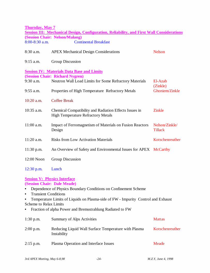
Thursday, May 7Session III: Mechanical Design, Configuration, Reliability, and First Wall Considerations(Session Chair: Nelson/Malang)8:00-8:30 a.m. Continental Breakfast
8:30 a.m. APEX Mechanical Design Considerations Nelson
9:15 a.m. Group Discussion
Session IV: Materials Data Base and Limits(Session Chair: Richard Nygren)9:30 a.m. Neutron Wall Load Limits for Some Refractory Materials El-Azab
(Zinkle)9:55 a.m. Properties of High Temperature Refractory Metals Ghoniem/Zinkle
10:20 a.m. Coffee Break
10:35 a.m. Chemical Compatibility and Radiation Effects Issues inHigh Temperature Refractory Metals
Zinkle
11:00 a.m. Impact of Ferromagnetism of Materials on Fusion ReactorsDesign
Nelson/Zinkle/Tillack
11:20 a.m. Risks from Low Activation Materials Kotschenreuther
11:30 p.m. An Overview of Safety and Environmental Issues for APEX McCarthy
12:00 Noon Group Discussion
12:30 p.m. Lunch
Session V: Physics Interface(Session Chair: Dale Meade)• Dependence of Physics Boundary Conditions on Confinement Scheme• Transient Conditions• Temperature Limits of Liquids on Plasma-side of FW - Impurity Control and ExhaustScheme to Relax Limits• Fraction of alpha Power and Bremsstrahlung Radiated to FW 1:30 p.m. Summary of Alps Activities
Mattas
2:00 p.m. Reducing Liquid Wall Surface Temperature with PlasmaInstability
Kotschenreuther
2:15 p.m. Plasma Operation and Interface Issues Meade
3rd APEX Meeting, May 6-8,98 -25- M.Z.Y, June 4, 1998
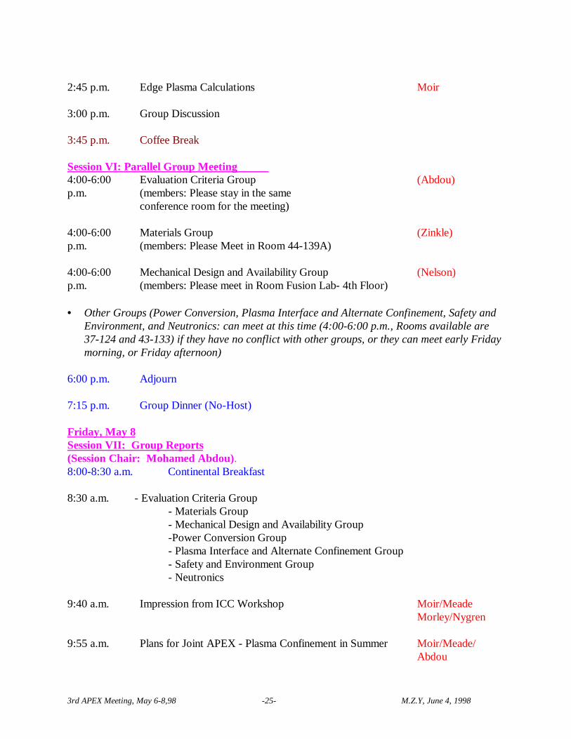
2:45 p.m. Edge Plasma Calculations Moir
3:00 p.m. Group Discussion
3:45 p.m. Coffee Break
Session VI: Parallel Group Meeting 4:00-6:00p.m.
Evaluation Criteria Group (members: Please stay in the same conference room for the meeting)
(Abdou)
4:00-6:00p.m.
Materials Group (members: Please Meet in Room 44-139A)
(Zinkle)
4:00-6:00p.m.
Mechanical Design and Availability Group (members: Please meet in Room Fusion Lab- 4th Floor)
(Nelson)
• Other Groups (Power Conversion, Plasma Interface and Alternate Confinement, Safety andEnvironment, and Neutronics: can meet at this time (4:00-6:00 p.m., Rooms available are37-124 and 43-133) if they have no conflict with other groups, or they can meet early Fridaymorning, or Friday afternoon)
6:00 p.m. Adjourn
7:15 p.m. Group Dinner (No-Host)
Friday, May 8Session VII: Group Reports(Session Chair: Mohamed Abdou).8:00-8:30 a.m. Continental Breakfast
8:30 a.m. - Evaluation Criteria Group- Materials Group- Mechanical Design and Availability Group-Power Conversion Group- Plasma Interface and Alternate Confinement Group- Safety and Environment Group- Neutronics
9:40 a.m. Impression from ICC Workshop Moir/MeadeMorley/Nygren
9:55 a.m. Plans for Joint APEX - Plasma Confinement in Summer Moir/Meade/Abdou

3rd APEX Meeting, May 6-8,98 -26- M.Z.Y, June 4, 1998
Session VIII: Resources, Man Power Requirements, and Technical Plans for DesignConcept Development and Analysis(Session Chair: Mohamed Abdou)10:05 a.m.10:15 a.m.10:25 a.m.10:35 a.m.10:45 a.m.10:50 a.m.11:00 a.m.
- Li2O Particulate Concept- Thick Liquid Metal Concept- Thin Liquid Metal Concept- He-Cooled Concept- Porous/Foam Wall Concept- LM Thick Free Flow- Other Concepts
SzeYingMorleyWong/NygrenGhoniem/AzabWoolleyMalang,Others ..
11:10 -Noon Discussion, Action Items, and Plan for Next Meeting
12:00 p.m. Close of the Meeting

3rd APEX Meeting, May 6-8,98 -27- M.Z.Y, June 4, 1998
VIII. List of Attendees
UCLA - APEX Planning Group Contact Information
Name Office Phone Facsimile E-mailMohamed Abdou (310) 206-0501 (310) 825-2599 [email protected] Dagher (310) 787-7097 (310) 787-7099 [email protected] El-Azab* (310) 825-7421 (310) 825-2599 [email protected] Ghoniem (310) 825-4866 (310) 206-4830 [email protected] Gulec (310) 206-7726 (310) 825-2599 [email protected] Morley (310) 206-1230 (310) 825-2599 [email protected] Uchimoto (310) 794-5354 (310) 825-2599 [email protected] Ying (310) 206-8815 (310) 825-2599 [email protected] Youssef(Group’s Secretary)
(310) 825-2879 (310) 825-2599 [email protected]
* Did not Attend Meeting
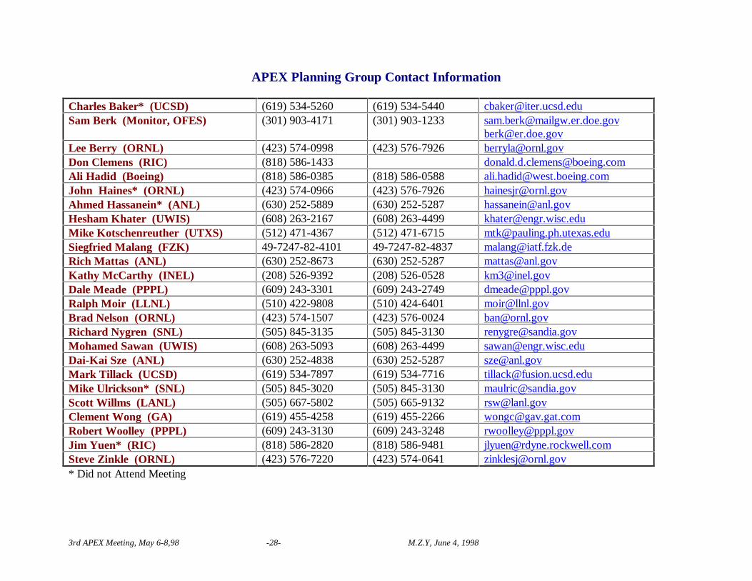
3rd APEX Meeting, May 6-8,98 -28- M.Z.Y, June 4, 1998
APEX Planning Group Contact Information
Charles Baker* (UCSD) (619) 534-5260 (619) 534-5440 [email protected] Berk (Monitor, OFES) (301) 903-4171 (301) 903-1233 [email protected]
[email protected] Berry (ORNL) (423) 574-0998 (423) 576-7926 [email protected] Clemens (RIC) (818) 586-1433 [email protected] Hadid (Boeing) (818) 586-0385 (818) 586-0588 [email protected] Haines* (ORNL) (423) 574-0966 (423) 576-7926 [email protected] Hassanein* (ANL) (630) 252-5889 (630) 252-5287 [email protected] Khater (UWIS) (608) 263-2167 (608) 263-4499 [email protected] Kotschenreuther (UTXS) (512) 471-4367 (512) 471-6715 [email protected] Malang (FZK) 49-7247-82-4101 49-7247-82-4837 [email protected] Mattas (ANL) (630) 252-8673 (630) 252-5287 [email protected] McCarthy (INEL) (208) 526-9392 (208) 526-0528 [email protected] Meade (PPPL) (609) 243-3301 (609) 243-2749 [email protected] Moir (LLNL) (510) 422-9808 (510) 424-6401 [email protected] Nelson (ORNL) (423) 574-1507 (423) 576-0024 [email protected] Nygren (SNL) (505) 845-3135 (505) 845-3130 [email protected] Sawan (UWIS) (608) 263-5093 (608) 263-4499 [email protected] Sze (ANL) (630) 252-4838 (630) 252-5287 [email protected] Tillack (UCSD) (619) 534-7897 (619) 534-7716 [email protected] Ulrickson* (SNL) (505) 845-3020 (505) 845-3130 [email protected] Willms (LANL) (505) 667-5802 (505) 665-9132 [email protected] Wong (GA) (619) 455-4258 (619) 455-2266 [email protected] Woolley (PPPL) (609) 243-3130 (609) 243-3248 [email protected] Yuen* (RIC) (818) 586-2820 (818) 586-9481 [email protected] Zinkle (ORNL) (423) 576-7220 (423) 574-0641 [email protected]* Did not Attend Meeting

3rd APEX Meeting, May 6-8,98 -29- M.Z.Y, June 4, 1998
IX. AppendicesAppendix I
SECRETARY’s ANNOUNCEMENTS
SUMMARY OF LAST MEETING- Distributed to participants. Thanks for Sessions Chairs who provided summaries of theirsessions. Action Items was developed during the meeting.- e-mail list is updated to include more participants/interested individuals in the study.
ACTION ITEMS FROM LAST MEETING (Attached):PLEASE REVIEW THE ITEMS IN YOUR AREA AND BE PREPARED TO UPDATEGROUP ON STATUS.
-Several documents and Technical Memos were provided to Secretary and added toAPEX Web Site (http://www.fusion.ucla.edu)::- Thermophysical and Mechanical Properties of V-(4-5)%Cr-(4-5)%Ti Alloys (S. J.Zinkle)- Thermophysical and Mechanical Properties of Fe-(8-9)%Cr Reduced Activation Steels(Steve Zinkle, J.P. Robertson and R.L. Klueh)- Thermophysical and Mechanical Properties of SiC/SiC Composites (S. J. Zinkle,L.L.Snead)- Damage rate in V.V. as a Function of Convective Layer Thickness (M.Z. Youssef)- Impact of Li-6 Enrichment of the Convective Layer on Damage and Heat Depositionrate in V.V. (M.Z. Youssef)- Results n NML Limits for the Porous Solid Wall-Liquid Lithium Concept (A. El-Azab)- Porous FW Concepts (A. El-Azab)
Prepared and sent to UCLA. Will be discussed this meeting.
APEX WEB SITE:PLEASE MAKE SURE TO GIVE SECRETARY A COPY OF YOURPRESENTATION FOR THIS MEETING. A COPY ON A DISC OR SENT AS ASOFTWARE DOCUMENT IS PREFERABLE.
PUBLICATIONS:An Overview paper on APEX will be presented by M. Abdou at 1998 ANS Annual Meeting andEmbedded Topical Meeting: June 7-11, 1998
APEX SecretaryM. Youssef, May 6, 1998

3rd APEX Meeting, May 6-8,98 -30- M.Z.Y, June 4, 1998
III. Action Items From Last Meeting (compiled by M. Youssef)(Taken from Summary of APEX Planning Group Meeting, January 12-14, 1998)
General Action Items or Observations
1) APEX will look at all magnetic confinement schemes. It is not limited to tokamaks.
2) The type of Tokamak (along with its design parameters) to be adapted as guidance in theAPEX study was chosen to be ARRIES-RS since it has high power density characteristics.(Alice to check with Mark Tillack (UCSD) and compile typical dimensions and parameters)
3) Plasma disruptions, and other plasma transients, will be considered as a non-limiting factor(free factor) in the APEX study. However, any concept to be developed should at least takefew (~2) disruptions and demonstrate that plasma startup can be performed. In general,concepts that can accommodate easily off-normal conditions will get credit for this.
4) Dai Kai Sze will work with each group concept to construct and identify an efficient powerconversion system.
5) Questions regarding safety should be directed to the Safety Group (K. McCarthy) once theyarise (by e-mail, no waiting)
6) Perform nuclear analysis to assess guidelines for concept developers with regard to damage,after heat, activation, etc. (M. Youssef, M. Sawan). Also, agree on methodology to be usedin the more detailed stage to evaluate tritium self sufficiency. In particular, agree on whattype of 3-D heterogeneous calculations to be done for tritium breeding.
7) Several P/FW/B/VV/C configurations to be explored and evaluated. These area. Conventional: P/FW/B/VV1/C/VV2b. Variation 1: P/FW/VV1/B/C/VV2 Blanket outside VVc. Variation 2: P/FWCB/B/VV1/C/VV2 FW is a conductance barrierd. Variation 3: P/FW/B/C/VV1/VV2 VV outside coile. Variation 4: P/FW/B/VV1/C/VV2 Vacuum Vessel is TF Coil
Specific Action Items
1) Mohamed Abdou suggested that Protecting FW Liquid could be the only material inside theVV in order to simplify maintenance. He requested evaluation of the various areas related tothis:
The protection requirements of the VV in this geometry (e.g. 1 ppm He, dpa limits, etc.)will be checked through nuclear analysis (M. Youssef).
Mechanical Design Group (Brad Nelson) will examine how this configuration simplifiesmaintainability and how the protecting liquid layer could be formed.

3rd APEX Meeting, May 6-8,98 -31- M.Z.Y, June 4, 1998
The kind of coolant in the VV will be explored (H2O, He, hydrogen-bearing material, Li,etc.). Kathy McCarthy will talk about hydrocarbons next meeting.
2) Steve Zinkle will provide M. Youssef with "Tables of Materials Properties" to be put on theWeb. Included with these tables are the properties of Foams (Nasr Ghoniem)
3) Anter El-Azab will find the limits (stress, temperature) of the materials provided by S. Zinkle.(e.g. Cu-Ni-Be, T-111, Nb-1Zr, TZM, etc.). Hydrogen content in material (e.g. Vanadium)will be considered in affecting these limits.
4) Explore the possibility of forming gaps in the flowing protecting liquid which could be usedfor penetration. Additionally, the instability of the magnetic field in the toroidal directioncould be a limiting factor to be examined (Neil Morley).
5) Next APEX Meeting is scheduled to be April 29- May 1, 1998 at UCLA. Alternate magneticConfinement Meeting will be held April 27-28, 1998 and arranged by Dale Meade. A personper concept will attend this meeting. Mohamed Abdou will draft a letter about APEX studyto this group.
6) Mike Ulrickson (SNL) and Clement Wong (GA) will examine a base FW of Tungsten andVanadium with Helium cooling system and assess the merit of these combinations on carryingaway HHF. UCLA will assist in the analysis as needed.
7) Perform elastic-plastic analysis for stress evaluation and operating limits (Anter El-Azab).
8) Brad Nelson will assist each concept group to develop a design that incorporates reasonablemargins and simplifies maintainability. He will stay with UCLA group after this meeting forthat purpose.
9) The Physics Interface Group (Dale Meade) will do the following:
− Critical review of impact of evaporated liquid (lithium, lead ) on plasma performance.Examine allowable evaporation rate and sputtering limits (there is a sputtering reportabout lead on the web, Mike Ulrickson)
− Define the plasma functional requirements that should be met to start plasma. (heating,fueling, control field, removing alpha particles, etc.)
− Provide UCLA (and others) with a representative Bremsstrahlung spectrum withtypical line radiation from impurities (agree on a standard temperature profile andcategorize/parameterize it for impurities). Currently, M. Youssef (UCLA) is usingITER plasma radiation for surface heating and will compare impact of various spectraon volumetric heat deposition in Li, Flibe, and Li17Pb83 liquid layers.

3rd APEX Meeting, May 6-8,98 -32- M.Z.Y, June 4, 1998
− Provide definition of representative physical penetration (circular, rectangular,triangular shape and dimension) for heating, fueling, and diagnostics.
− Merits/disadvantages of using rectangular FW as opposed to FW that follows thecontours of plasma edge. Examine the issue of the need to have a conducting FW (atrade-off question).
10) The concepts that will be further examined/discussed next meeting are:
UCLA: (1) Convective Liquid wall (Li, Flibe) (2) Porous FW filtrated with liquid (non-evaporated) (3) Thick non-conducting FW
PPPL: (4) Magnetically restrained thick FW of Lithium (conducting)
− UCLA (N. Morley) will examine the EM forces on the moving liquid(i.e. include MHD in the analysis) which could lead to instabilities.Consider turbulence in the falling liquid layer.
− UCLA (Alice Ying) will examine evaporation of falling liquid as amechanism to remove heat. Will work with PPPL (Bob Woolley) asneeded on its concept.
ANL: (5) Free Falling Li2O Particulates.
− Dai kai Sze will perform more detailed thermal analysis of that conceptby next meeting, including heat exchangers.
(6) Purse using foams in FW (Nasr Ghoniem) and examine evaporation of liquidfrom FW. Develop a complete thermal hydraulic cycle for that concept by nextmeeting and improve thermodynamic efficiency.
UW: (7) Sprayed-FW concept