Summary of CDR reportwestrocketry.com/sli2011/FRR_MadisonWest2011_Bamboo.docx · Web viewThe motor...
89
March 21, 2011 A Comprehensive Study of Healing of Fargesia Fungosa from Hypergravity-Induced Damage Madison West High School
Transcript of Summary of CDR reportwestrocketry.com/sli2011/FRR_MadisonWest2011_Bamboo.docx · Web viewThe motor...

March 21, 2011
A Comprehensive Study of Healing of Fargesia Fungosa from Hypergravity-Induced Damage
Madison West High School
Back: Suhas, Max, Peter, Jacob E, DuncanFront: Yifan, Enrique, Jacob K
SLI 2011 Flight Readiness Review
Madison West High School Senior Team SLI 2011 CDR
Table of Contents
Summary of CDR report...................................................................................................5Team Summary............................................................................................................5Launch Vehicle Summary.............................................................................................6Payload Summary........................................................................................................6
Changes made since CDR...............................................................................................8Changes made to vehicle criteria.................................................................................8Changes made to payload criteria................................................................................8Changes made to activity plan.....................................................................................8
Vehicle Criteria.................................................................................................................9Major Milestones Schedule.......................................................................................9
Testing and Design of Vehicle......................................................................................9Flight Reliability Confidence......................................................................................9Static Testing............................................................................................................9Verification Plan and Status....................................................................................10Matrix Legend.........................................................................................................11Proper Use of Materials..........................................................................................11Rational for material choice....................................................................................11Strength of Assembly..............................................................................................11Integrity of Design...................................................................................................11Approach to Workmanship......................................................................................12Safety and Mitigations.............................................................................................12Full Scale Test Results...........................................................................................13
Recovery Subsystem..................................................................................................14Safety and Failure Analysis.....................................................................................15
Mission Performance Predictions...............................................................................16Mission Statement..................................................................................................16
Predictions and Analysis............................................................................................25Entire Vehicle..........................................................................................................25Sustainer.................................................................................................................26Propulsion System..................................................................................................29Wind Speed vs. Altitude..........................................................................................31Thrust Profile...........................................................................................................32Acceleration Profile.................................................................................................32
-2-

Madison West High School Senior Team SLI 2011 CDR
Safety and Environment (Vehicle)..............................................................................34Safety Officer..........................................................................................................34Risks and Mitigations..............................................................................................34Physical Risks.........................................................................................................34Rocket/Payload Risks.............................................................................................34Toxicity Risks..........................................................................................................36
Assembly and Launch Operation Procedures............................................................37Booster....................................................................................................................37Sustainer.................................................................................................................37Disarming Procedure (only if motor doesn’t ignite).................................................38Recovery Preparation.............................................................................................38Motor Preparation...................................................................................................38Igniter Installation....................................................................................................38Setup on Launcher..................................................................................................38Troubleshooting......................................................................................................39Post flight inspection...............................................................................................39Environmental Concerns.........................................................................................40
Payload Integration.....................................................................................................41Payload Criteria..............................................................................................................42
Creativity and originality..........................................................................................42Uniqueness or significance.....................................................................................42Suitable level of challenge......................................................................................42
Science Value.............................................................................................................43Science payload objectives.....................................................................................43State the mission success criteria...........................................................................43Experimental logic, scientific approach, and method of investigation.....................44Meaningful test and measurement, variables and controls.....................................45Relevance of expected data, along with an accuracy/error analysis, including tables and plots.................................................................................................................46Provide detailed experiment process procedures...................................................46Data Acquisition......................................................................................................47
Experiment Design of Payload...................................................................................47Verification Matrix.......................................................................................................54Application of engineering, functionality, and feasibility..............................................55Flight performance predictions (Payload)...................................................................55
-3-
Madison West High School Senior Team SLI 2011 CDR
Flight preparation procedures (Payload)....................................................................55Specify approach to workmanship as it relates to mission success...........................56Discuss completed component, functional, or static testing.......................................56
Assembly........................................................................................................................57Clear details of how the rocket is assembled.............................................................57Integration and compatibility simplicity.......................................................................57Structural integrity for flight.........................................................................................58Quality of construction................................................................................................58
Safety and Environment (Payload).................................................................................59Educational engagement............................................................................................61
Community Support................................................................................................61Outreach Programs.................................................................................................62
Conclusion.....................................................................................................................63
-4-

Madison West High School Senior Team SLI 2011 CDR
Summary of CDR reportTeam Summary
School Name Madison West High School
Title of ProjectA Comprehensive Study of Healing of Fargesia Fungosa Plants from Hypergravity Induced Damage
Educators and Mentors
Administrative Staff MemberWest High School Principal Ed HolmesMadison West High School, 30 Ash St., Madison, WI, 53726Phone: (608) 204-4104E-Mail: [email protected]
Team OfficialMs. Christine Hager, Biology InstructorMadison West High School, 30 Ash St., Madison, WI 53726Phone: (608) 204-3181E-Mail: [email protected]
Educators and Mentors
Pavel Pinkas, Ph.D., Senior Software Engineer for DNASTAR, Inc.1763 Norman Way, Madison, WI, 53705Work Phone: (608) 237-3068Home Phone: (608) 957-2595Fax: (608) 258-3749E-Mail: [email protected]
Brent Lillesand4809 Jade Lane, Madison, WI 53714Phone: (608) 241-9282E-mail: [email protected]
Jeffrey A. Havlena118 Richland Lane Madison, WI 53705Phone: (608) 238-6880E-Mail: [email protected]
-5-
Madison West High School Senior Team SLI 2011 CDR
-6-

Madison West High School Senior Team SLI 2011 CDR
Scientific ConsultantsDonna E. FernandezDept. of Botany, UW-MadisonPhone: (608) 262-9033E-Mail: [email protected]
Simon GilroyDept. of Botany, UW-MadisonPhone: (608) 262-4008E-Mail: [email protected]
Patrick H MassonDept. of Genetics, UW-MadisonPhone: (608) 265-2312E-Mail: [email protected]
Section 508 Consultant: Ms. Ronda SolbergDNASTAR, Inc. (senior software designer)3801 Regent St, Madison, WI 53705E-Mail: [email protected]
Associated NAR Chartered Section #558President: Mr. Scott T. GoebelPhone: (262) 634-3971E-Mail: [email protected]://www.wooshrocketry.org
Wisconsin Organization Of Spacemodeling Hobbyists (WOOSH) is a chartered section (#558) of the National Association of Rocketry. They assist Madison West Rocketry with launches, mentoring, and reviewing.
-7-
Madison West High School Senior Team SLI 2011 CDR
Launch Vehicle Summary
A two stage rocket 3" in diameter, 15ft in length, propelled by two J-class motors, will be used to generate two distinct acceleration profiles (high-g and low-g). Each stage will carry a payload of young bamboo plants that will be subjected to flight stresses, mainly gravitational shocks.
Payload Summary
We will be investigating the effect of hypergravity on the growth and healing of Fargesia Fungosa shoots. Hypergravity research has been done on various plants in laboratories, but because they are done within centrifuges, rapid acceleration and deceleration cannot be easily produced. Although our rocket will not reach extremely high acceleration values, it will go through a rapid acceleration which cannot be obtained in a centrifuge. After a successful flight we will test the variables pertaining to our experiment.
-8-

Madison West High School Senior Team SLI 2011 CDR
Changes made since CDR
Changes made to vehicle criteriaThe motors have been changed from the Aerotech manufactured motors to the CTI-J1055V-MAX and the CTI-K2045V-MAX in the booster and sustainer, respectively. Otherwise the vehicle criteria remain the same.
Changes made to payload criteriaNo significant changes have been made to payload criteria.
Changes made to activity planNo significant changes have been made to the activity plan.
-9-

Madison West High School Senior Team SLI 2011 CDR
Vehicle Criteria
Major Milestones ScheduleMajor Milestones
26 Full Configuration Launch28-31 FRR presentations (tentative)
April 201110 Rocket Ready for Launch in Huntsville13 Travel to Huntsville
14-15 Rocket Fair/hardware and safety check16 Launch day17 Return Home
May 20119 Post-Launch Assessment Review (PLAR) due
Table 1: Timeline of important events
Testing and Design of Vehicle
Flight Reliability ConfidenceThe full scale vehicle will be able to meet the mission success criteria. It has been tested in a test flight of the sustainer. Although there was a major motor malfunction, changes to the motor selection have eliminated the risk of such an event reoccurring. The full configuration (both stages) will be tested on March 20.
Static TestingWe completed static testing for the sustainer of our vehicle on February 19 th. All charge sizes for the sustainer were adequate and all parachutes deployed. The first test flight confirmed our findings in static testing that the charges are sufficient. The static testing for the booster will be completed prior to the launch.
-10-

Madison West High School Senior Team SLI 2011 CDR
Verification Plan and StatusVerification Tests
V1 Integrity Test: applying force to verify durability.V2 Parachute Drop Test: testing parachute functionality.V3 Tension Test: applying force to the parachute shock cords to test durabilityV4 Prototype Flight: testing the feasibility of the vehicle with a scale model.V5 Functionality Test: test of basic functionality of a device on the groundV6 Altimeter Ground Test: place the altimeter in a closed container and decrease air pressure to simulate altitude changes. Verify that both the apogee and preset altitude events fire. (Estes igniters or low resistance bulbs can be used for verification).V7 Electronic Deployment Test: test to determine if the electronics can ignite the deployment charges.V8 Ejection Test: test that the deployment charges have the right amount of force to cause parachute deployment and/or planned component separation.V9 Computer Simulation: use RockSim to predict the behavior of the launch vehicle.V10 Integration Test: ensure that the payload integrates precisely into the vehicle, and is robust enough to withstand flight stresses.
Tested ComponentsC1: Body (including construction techniques)
C2: Altimeter
C3: Data Acquisition System (custom computer board and sensors)
C4: Parachutes
C5: Fins
C6: Payload
C7: Ejection charges
C8: Launch system
C9: Motor mount
C10: Telemetry and Beacons
C11: Shock cords and anchors
C12: Rocket stability
C13: Second stage separation and ignition electronics/charges
-11-

Madison West High School Senior Team SLI 2011 CDR
Matrix LegendXXX: Planned TestsXXX: Finished Tests
V 1 V 2 V 3 V 4 V 5 V 6 V 7 V 8 V 9 V 10
C 1 PC 2 PC 3 P C 4
C 5
C 6
C 7
C 8 PC 9
C 10
C 11
C 12
C13
Table 2: Verification matrix for the vehicleOur verification plan is two thirds complete; however, all of the necessary tests will be completed before our departure to Huntsville.
Proper Use of MaterialsRefer to Integrity of Design.
Rational for material choiceThe materials selected for the full scale rocket were based on strength and weight constraints. Refer to Strength of Assembly and Integrity of Design.
Strength of AssemblyThe rocket has been assembled using tested high power rocketry components. All attachment points in the rocket that are non-separating have been attached using metal screws and all separating junctions of the rocket have been secured using shear pins if required. All attachment points have been properly aligned. The motor mounts are made using a combination of J.B. Weld and Aeropack motor retention systems.
Integrity of DesignWe have chosen standard high power rocketry materials – namely G-10 fiberglass for the fins, half-inch plywood for the bulkheads, fiberglass tubing for the body, stainless steel hardware – to ensure structural integrity of the vehicle during flight and landing. The standard trapezoidal shape and proper size of our fins ensures the stable flight of our vehicle and reduces the risk of fin flutter during ascent. We will employ an Aeropack motor retention system to ensure motor does not dislodge during flight. Our use of West Systems Epoxy on the full scale vehicle will ensure the robustness of load bearing structural sections of the rocket; specifically, attachment points of the fins to the body
-12-

Madison West High School Senior Team SLI 2011 CDR
tubes, connections of couplers to body tubes, and fixture points of permanent bulkheads and centering rings within body tubes. The rocket body is constructed of fiberglass tubing due to the high forces integral to our experiment
Approach to WorkmanshipThe mission success of our project depends on our approach to workmanship. The demands of our project success require that the upmost care be taken during the construction of our vehicle. Members of our team have had extensive experience in the construction of rockets and use procedures that ensure vehicle robustness. During the construction of the vehicle, team members took care to ensure that the final vehicle is clean and attractive. Before our departure to Huntsville, the full scale rocket will be painted to enhance its aesthetics.
Safety and MitigationsRefer to Risks and Mitigations in Safety and Environment (Vehicle).
-13-

Madison West High School Senior Team SLI 2011 CDR
Full Scale Test Results
Figure 1: Sustainer liftoff (AT-J1299N)
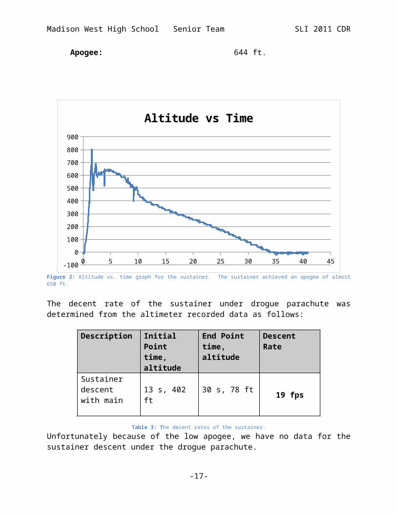
The sustainer had a straight boost however late in the boost the threads on the aft closure of our motor casing for the J1299N failed. This resulted in a burst of pressure which destroyed the fin assembly. Rocket continued to apogee at a height of 644 feet at a time of 4.5 seconds. This is significantly lower than our projected apogee of approximately 2000 feet. We are attributing this to the failure of the motor, which resulted in a loss of thrust and stability (after the destruction of fin assembly).
Liftoff Weight: 7.0 kgMotor: J1299NLength: 112 inchesDiameter: 3inStability Margin (sustainer): 7.6 calibersApogee: 644 ft.
-14-

Madison West High School Senior Team SLI 2011 CDR
0 5 10 15 20 25 30 35 40 45-100
0
100
200
300
400
500
600
700
800
900
Altitude vs Time
Figure 2: Altitude vs. time graph for the sustainer. The sustainer achieved an apogee of almost 650 ft.
The decent rate of the sustainer under drogue parachute was determined from the altimeter recorded data as follows:
Description Initial Pointtime, altitude
End Pointtime, altitude
Descent Rate
Sustainer descent with main
13 s, 402 ft 30 s, 78 ft 19 fps
Table 3: The decent rates of the sustainer.
Unfortunately because of the low apogee, we have no data for the sustainer descent under the drogue parachute.
Because of the high failure rate of the Aerotech motors, we have decided to change our propulsion to CTI Pro54 motors, namely J1055Vmax for the booster and K2045Vmax for the sustainer. A test flight is scheduled for March 26th and an update to our FRR will be issued as soon as we have the data from the test flight analyzed. The simulation for CTI motor combination are shown below.
The drag coefficient has not been calculated because of the catastrophic motor failure on the first test flight. A test flight with new propulsion choice is scheduled.
-15-

Madison West High School Senior Team SLI 2011 CDR
Recovery Subsystem
Our rocket will deploy a total of three parachutes. We will use a standard deployment scheme with redundant charges and ejection triggers to ensure proper ejection, and we will determine and verify the sizes of parachutes and ejection charges with static tests.
Two parachutes are housed in the sustainer. The sustainer drogue will be deployed at sustainer’s apogee, slowing and stabilizing the rocket’s descent. The sustainer’s main chute will be deployed at 500ft, slowing the rocket to a safe descent rate.
The other parachute is housed in the booster. This recovery system will also deploy at 500ft.
Vehicle RecoveryParachute name Parachute size [in] Descent rate [ft/] Ejection charge size [g]
BoosterMain 60 21 2.8
SustainerDrogue 14 89 2.0Main 60 21 2.8Separation N/A N/A 1.0
Table 4: Vehicle Recovery
The ejection charge sizes were calculated with the formula
Wp= dP * V / (R * T) * 454/12
where
Wp - ejection charge weight in grams.dP - ejection charge pressure, 15psi.V - free volume in cubic inches.R- combustion gas constant, 22.16 ft-lb/degrees R*mol FFFF black powder.T – combustion gas temperature, 3307 degrees R
Because of the increasingly limited availability and handling restriction for black powder, we are using Triple Se7en Pyrodex for our ejection charges. We have developed a wrapping method that ensures proper pressurization of the charges and we have been testing Pyrodex charges for entire SLI2011 season. Our TARC teams in 2007, 2008 and 2009 seasons used Pyrodex charges exclusively.
-16-
Madison West High School Senior Team SLI 2011 CDR
Safety and Failure AnalysisRefer to Safety and Environment (Vehicle).
-17-

Madison West High School Senior Team SLI 2011 CDR
Mission Performance Predictions
Mission StatementTo have a successful mission we need to reach one mile AGL and Subject the payload to a large acceleration. The rocket will be 186 inches long, with a 3 inch diameter for both the booster and the sustainer. It has a liftoff weight of 13.2 kilograms (sustainer itself is 7.5 kilograms). The proposed vehicle and propulsion options are discussed in detail below. The propulsion comes from a K-class motor in the booster and a J-class motor in the sustainer and total impulse is 2155 Ns. The vehicle will launch from a large, 12 foot, rail due to its length.
Mission statement, requirements, and mission success criteriaFor a successful mission, the vehicle must reach (but not exceed) 5280ft, deliver the payload, and recover safely.
1. The vehicle carries an innovative scientific payload. The bamboo shoots will fly on board through the two-stage flight trajectory. The post-flight analysis of the bamboo shoots for cell structure damage will generate qualitative data for a comprehensive study of bamboo healing from hypergravity-induced damage.
Figure 3: Horizontally Oriented Bamboo Chamber (right) and Vertically Oriented Bamboo Chamber (left) are shown above; each chamber is equipped with a temperature sensor (T), humidity sensor (H), Data Processing and Storage System (a printed circuit board on top of each chamber), agar, and bamboo shoots.
-18-

Madison West High School Senior Team SLI 2011 CDR
2. RockSim simulations and test flights will aid us in the creation of a two-stage rocket with a maximum achievable acceleration that has an apogee altitude close to, but not exceeding, 5,280ft above ground level. The rocket needs 200g of ballast.
Figure 4: Altitude vs. Time Graph
Wind Speed[mph]
Altitude[ft]
Percent Change in Altitude
0 5250 0.00%5 5244 0.11%10 5226 0.44%15 5199 0.94%20 5167 1.52%
Table 5: Wind Speed vs. Flight Apogee
As shown in the table above, the rocket apogee will not vary significantly with the wind speed. There will be only 1.5% altitude loss in the worst case event (wind speed at the NAR limit of 20mph).
3. Our recovery system electronics will include the following characteristics:a. Redundant altimeters-for safetyb. Each altimeter will be equipped with an external arming switch and battery
that is not shared with any other electronic device in the rocket.c. Every arming switch for each altimeter will be accessible from the exterior
of the rocket, via a secured door on the fiberglass body.
-19-

Madison West High School Senior Team SLI 2011 CDR
d. All arming switches are able to lock in the on position for launch.e. The recovery system is designed to be armed while the rocket is on the
pad.f. The vehicle will transport separate electronics for each system: the
recovery system and the payload each have independent electronics and power sources.
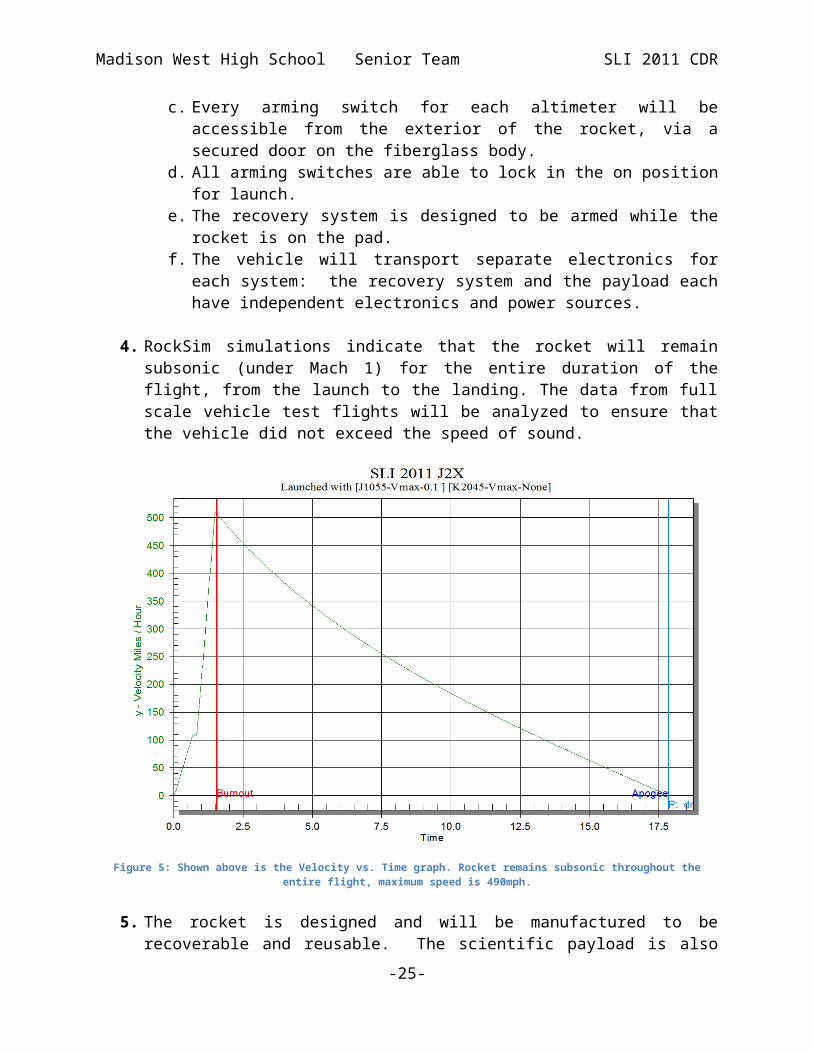
4. RockSim simulations indicate that the rocket will remain subsonic (under Mach 1) for the entire duration of the flight, from the launch to the landing. The data from full scale vehicle test flights will be analyzed to ensure that the vehicle did not exceed the speed of sound.
Figure 5: Shown above is the Velocity vs. Time graph. Rocket remains subsonic throughout the entire flight, maximum speed is 490mph.
5. The rocket is designed and will be manufactured to be recoverable and reusable. The scientific payload is also designed to be recoverable and reusable, and the landing should cause as little damage as possible to the actual bamboo shoots in order to lessen its effect on the experiment. Both the vehicle and the payload will be able to launch again on the same day with no preceding repairs or modifications to either.
6. Separation at apogee will only involve the deployment of the drogue parachute. Payload components will not deploy at launch, or throughout the flight, thus the drift will be minimal.
-20-

Madison West High School Senior Team SLI 2011 CDR
7. Dual deployment recovery will be used.
Figure 6: The Mission Profile Chart includes the flight sequences for both stages and is described with more detail below
-21-

Madison West High School Senior Team SLI 2011 CDR
Event Time [s] Altitude [ft]
Velocity [mph]
Triggering Condition
Triggering Device
1 Launch 0.0 0 0 Ready to launch Launch Control
2Separation 0.7 75 125 Booster burnout
(negative acceleration)
Flight computer (accelerometer)
3Sustainer burn 0.8 – 1.5 85 - 400 125 -
500Stage 2 ignition delay elapses
Flight computer (timer)
4Sustainer apogee/Deployment
17.5 5250 0 Apogee Deployment altimeter (MAWD)
2a
Booster apogee, main deployment
11.0 ~700 0 Apogee Deployment altimeter (MAWD)
3a
Booster touchdown
76.0 0 0 - -
5 Descent under drogue
17.5-64.0
5250-500
-60 Drogue deployment
-
6Main deployment/Descent
64 500 -13 500ft reached Deployment altimeter (MAWD)
7 Sustainer touchdown
88 0 0 - -
Table 6: Flight events, including time and altitude of each event, condition that trigger an event and a device that executes the action associated with the event.
8. Removable shear pins will be used for both the main parachute compartment and the drogue parachute compartment.
We shall use removable nylon shear pins of sufficient strength to prevent premature rocket separation. The size and number of shear pins will be fine tuned during test flights.
9. The vehicle, or any un-tethered sections, will have a descent rate under the main parachute(s) between 17ft/s and 22ft/s, inclusive.
Vehicle RecoveryParachute name Parachute size [in] Descent rate [ft/s] Ejection charge size [g]
BoosterMain 60 18 2.8
SustainerDrogue 14 90 2.0Main 60 20 2.8
Table 7: The parachute size, descent rate and estimated ejection charge size for the main and drogue parachutes
-22-

Madison West High School Senior Team SLI 2011 CDR
10.The vehicle, or any un-tethered sections, will have a descent rate under the drogue parachute(s) between 50 and 100ft/s, inclusive. Only the second stage of our vehicle will be use drogue controlled descent and the estimated descent rate under drogue for this stage is 90ft/s. The first stage uses single deployment (main parachute deployed at the stage apogee).
11.Each rocket will be capable of being prepared for flight at the launch site within 4 hours, from the time the waiver opens at the field until RSO inspections have been successfully completed.
We shall use a vehicle preparation checklist so that we can prepare the rocket in the allotted time.
12.All vehicle and payload components will be designed to land within 2500 ft. of the pad under all safe wind conditions. The table below indicates that even in the worst case scenario (wind speed at the NAR safety limit of 20mph) both stages will land within 2,500ft from the launch pad.
Wind speed vs. Rocket driftWind speed [mph] Booster drift [ft] Sustainer drift [ft]
0 0 05 621 576
10 1243 115215 1865 172820 2487 2304
Table 8: Amount of rocket drift with varying wind speed. The table has been computed assuming sustainer apogee of 5,280ft, booster apogee of 1,650ft, sustainer main parachute deployment altitude of 700ft, booster main parachute deployment altitude of 1,650ft, drogue descent rate of 90ft/s and main parachute descent rates of 20ft/s.
13.After being fully armed for launch, the rocket will be capable of remaining on the pad for 1 hour before launching without losing the functionality of any vehicle or payload component.
We shall construct the payload so that it can sit on the pad for at least one hour, and ensure that all batteries can run their circuits for at least one hour. Battery capacity testing will be conducted during payload construction and development; new batteries will be used for each flight. A preliminary review of the payload design has not identified any possible power bottleneck.
14.Rockets will be launched from a standard firing system (provided by the Range) that does not need additional circuitry or special ground support equipment to initiate the flight or complicate a normal 10-second countdown.
We shall build the rocket using standard rail buttons and standard motor ignition systems to ensure that no additional equipment is needed for the launch. Staging, deployment, and payload functionality are controlled by autonomous onboard devices with lift-off detection capability (allowing
-23-

Madison West High School Senior Team SLI 2011 CDR
most of the electronics to remain in the shallow sleep mode until the liftoff).
15.The experiment will be designed to follow the scientific method. See section on independent and dependent variables for more information.
16.Each stage of the rocket will contain a telemetry device consisting from a GPS receiver and 900MHz transceiver (in transmitter mode) to aid in recovery.
GPS satellite data will be received by the GPS receiver. The GPS receiver transfers the data over serial link to flight computer that will instruct 900MHz XBee transceiver to transmit the data. Another 900MHz XBee transceiver (located on the ground) will receive the GPS data broadcasted by the rocket and the GPS location will be entered into a handheld GPS device. The handheld GPS will guide the recovery to the landing site.
Figure 7: Diagram of satellite-based telemetry system
17.The vehicle will be designed to reach the correct altitude using commercially available rocket motors with a total impulse of less than 4,000 Ns. The total impulse of the J1055 and the K2045 is approximately 2150Ns. The motors will
-24-
Madison West High School Senior Team SLI 2011 CDR
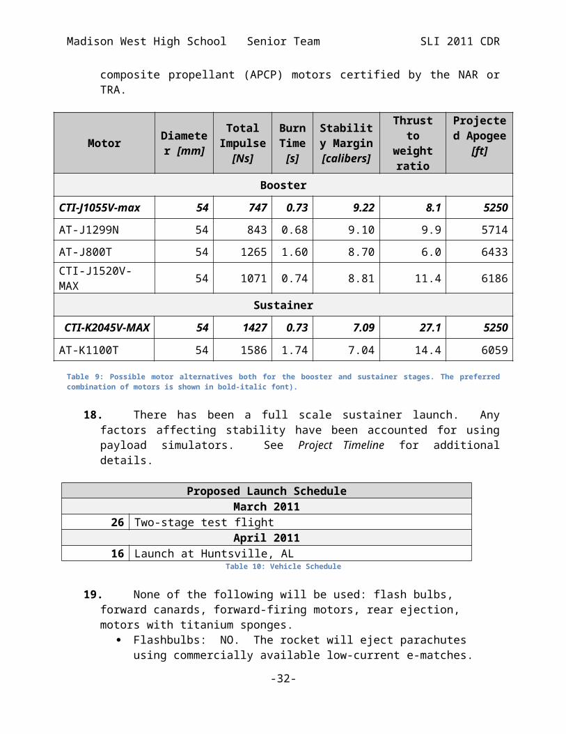
contain commercially available ammonium perchlorate composite propellant (APCP) motors certified by the NAR or TRA.
Motor Diameter [mm]
Total Impulse
[Ns]
Burn Time
[s]
Stability Margin
[calibers]
Thrust to weight ratio
Projected Apogee
[ft]Booster
CTI-J1055V-max 54 747 0.73 9.22 8.1 5250
AT-J1299N 54 843 0.68 9.10 9.9 5714
AT-J800T 54 1265 1.60 8.70 6.0 6433
CTI-J1520V-MAX 54 1071 0.74 8.81 11.4 6186
Sustainer
CTI-K2045V-MAX 54 1427 0.73 7.09 27.1 5250
AT-K1100T 54 1586 1.74 7.04 14.4 6059
Table 9: Possible motor alternatives both for the booster and sustainer stages. The preferred combination of motors is shown in bold-italic font).
18.There has been a full scale sustainer launch. Any factors affecting stability have been accounted for using payload simulators. See Project Timeline for additional details.
Proposed Launch ScheduleMarch 2011
26 Two-stage test flightApril 2011
16 Launch at Huntsville, ALTable 10: Vehicle Schedule
19.None of the following will be used: flash bulbs, forward canards, forward-firing motors, rear ejection, motors with titanium sponges.
Flashbulbs: NO. The rocket will eject parachutes using commercially available low-current e-matches.
Forward canard fins: NO (cf. Vehicle Design). Forward-firing motors: NO. Rear-ejection parachute designs: NO (standard e-bay coupling
arrangement will be used for parachute deployment). Motors which expel titanium sponges: NO. None of our proposed motors
contain titanium sponges.
-25-

Madison West High School Senior Team SLI 2011 CDR
20.A final launch and safety checklist will be included in the FRR and used during the safety inspection and on launch day. The checklist will be continuously updated as the project progresses. Test flights will be used to fine tuned and test the checklist.
21.Students will do all of the work on the project except for handling motors and black powder charges.
-26-

Madison West High School Senior Team SLI 2011 CDR
Predictions and Analysis
Entire Vehicle
Figure 8: A two dimensional schematic of the entire rocket. Stability margin for the entire vehicle is 8.95 calibers.
Vehicle Parameters
Length[in]
Mass[kg]
Diameter [in]
Motor Selection
Stability Margin
[calibers]Thrust to
weight ratio
183 13.3 3 CTI-J1055 9.22 8.1
Table 11: The rocket’s dimensions, stability, and propulsion
The figure below shows all compartments and sections of our rocket. Each stage will contain one payload module. We will use standard dual deployment for the sustainer and single deployment for the booster.
Figure 9: A three dimensional schematic of the entire rocket
Letter Part Letter Part
A Nosecone HSustainerMotor Mount and Interstage Coupler
B Sustainer Main Parachute I Booster
Parachute
C SustainerE-Bay J Booster E-bay
D Sustainer Drogue Parachute K Booster Payload
E Sustainer Payload L BoosterFins
-27-
D L I
MJ I
K I
I
G
HFECBA

Madison West High School Senior Team SLI 2011 CDR
Letter Part Letter Part
F Telemetry/Staging Electronics M Booster Motor Mount
G Sustainer Fins
Table 12: Rocket sections and parts
Sustainer
Figure 10: A two dimensional schematic of the sustainer part of the rocket. The stability margin for the sustainer is 7.18 calibers.
Sustainer Parameters
Length [in]
Mass[kg]
Diameter [in]
Motor Selection
Stability Margin
[calibers]
Thrust to weight ratio
109 7.8 3 CTI-K2045 7.09 26.9
Table 13: The dimensions of the sustainer, stability margin, and primary propulsion choice.
Figure 11: A three dimensional schematic of the sustainer
-28-

Madison West High School Senior Team SLI 2011 CDR
Figure 12: The Mission Profile Chart includes the flight sequences for both stages and is described with more detail below
Event Time [s] Altitude Velocity Triggering Triggering
-29-

Madison West High School Senior Team SLI 2011 CDR
[ft] [mph] Condition Device
1 Launch 0.0 0 0 Ready to launch Launch Control
2Separation 0.7 75 125 Booster burnout
(negative acceleration)
Flight computer (accelerometer)
3Sustainer burn 0.8 – 1.5 85 - 400 125 -
500Stage 2 ignition delay elapses
Flight computer (timer)
4Sustainer apogee/Deployment
17.5 5250 0 Apogee Deployment altimeter (MAWD)
2a
Booster apogee, main deployment
11.0 ~700 0 Apogee Deployment altimeter (MAWD)
3a
Booster touchdown
76.0 0 0 - -
5 Descent under drogue
17.5-64.0
5250-500
-60 Drogue deployment
-
6Main deployment/Descent
64 500 -13 500ft reached Deployment altimeter (MAWD)
7 Sustainer touchdown
88 0 0 - -
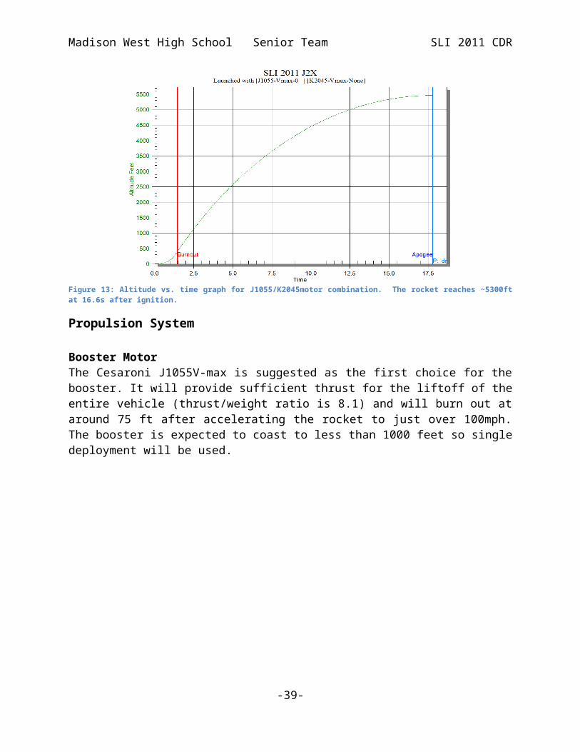
The graph below shows the simulated flight profile for J1055/K2045 motor combination. A significant increase in slope is visible shortly after the first stage burnout (.7s) and the sustainer reaches the apogee of 5250 ft (we have yet to get a solid Cd Value to confirm these predictions but our full scale flight will confirm this). The vehicle sustainer arrives to apogee 17.5s after the ignition.
-30-

Madison West High School Senior Team SLI 2011 CDR
Figure 13: Altitude vs. time graph for J1055/K2045motor combination. The rocket reaches ~5300ft at 16.6s after ignition.
Propulsion System
Booster MotorThe Cesaroni J1055V-max is suggested as the first choice for the booster. It will provide sufficient thrust for the liftoff of the entire vehicle (thrust/weight ratio is 8.1) and will burn out at around 75 ft after accelerating the rocket to just over 100mph. The booster is expected to coast to less than 1000 feet so single deployment will be used.
Figure 14: Thrust profile for CTI-J1055
-31-
Madison West High School Senior Team SLI 2011 CDR
Motor Length [mm]
Diameter [mm]
Average Impulse [N]
Total Impulse [Ns]
Burn Time [s]
CTI-J1055 V-max 236 54 1057 747 0.73Table 14: Primary booster motor
Sustainer MotorAfter the separation from the booster, the K2045 motor will deliver the sustainer to the target altitude. The maximum estimated speed is 500 mph and the motor will burn for 0.73s.
Figure 15: Thrust profile for K2045
Motor Length [mm]
Diameter [mm]
Average thrust [N]
Total Impulse
[Ns]Burn Time
[s]
CTI-K2045V-max 404 54 2045 1408 0.73Table 15: Primary sustainer motor
-32-

Madison West High School Senior Team SLI 2011 CDR
Wind Speed vs. AltitudeThe effect of the wind speed on the apogee of the entire flight is investigated in the table below. Even under the worst possible conditions (wind speeds 20mph, the NAR safety limit) the flight apogee will differ by only 1.5% from the apogee reached in windless conditions.
Wind Speed[mph]
Altitude[ft]
Percent Change in Altitude
0 5250 0.00%5 5244 0.11%10 5226 0.44%15 5199 0.94%20 5167 1.52%
Table 16: Flight apogee vs. wind speed
-33-

Madison West High School Senior Team SLI 2011 CDR
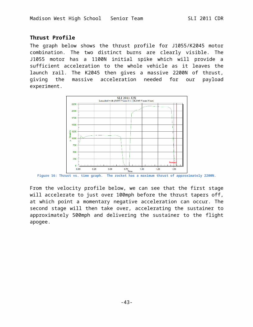
Thrust ProfileThe graph below shows the thrust profile for J1055/K2045 motor combination. The two distinct burns are clearly visible. The J1055 motor has a 1100N initial spike which will provide a sufficient acceleration to the whole vehicle as it leaves the launch rail. The K2045 then gives a massive 2200N of thrust, giving the massive acceleration needed for our payload experiment.
Figure 16: Thrust vs. time graph. The rocket has a maximum thrust of approximately 2200N.
From the velocity profile below, we can see that the first stage will accelerate to just over 100mph before the thrust tapers off, at which point a momentary negative acceleration can occur. The second stage will then take over, accelerating the sustainer to approximately 500mph and delivering the sustainer to the flight apogee.
Figure 17: Velocity vs. time graph. The booster motor burns out at 0.7s and the sustainer motor burns out at about 1.5 seconds. After burnout the rocket slows down gradually until it reaches apogee.
-34-

Madison West High School Senior Team SLI 2011 CDR
Acceleration ProfileThe graph below depicts the estimated acceleration profile. Two separate peaks correspond to the two burns. Our rocket will be robust enough to endure the 25g+ acceleration shocks.
Figure 18: Acceleration vs. time graph. The rocket has a maximum acceleration of approximately 9g for the booster and a maximum almost 30g for the sustainer’s burn.
-35-

Madison West High School Senior Team SLI 2011 CDR
Safety and Environment (Vehicle)
Safety OfficerOur Safety officer is Yifan Li.
Risks and Mitigations
Physical RisksRisks Consequences Mitigation
Saws, knives, Dremel tools, band saws
Laceration All members will follow safety procedures and use protective devices to minimize risk
Sandpaper, fiberglass
Abrasion All members will follow safety procedures and use protective devices to minimize risk
Drill press Puncture wound All members will follow safety procedures and use protective devices to minimize risk
Soldering iron Burns All members will follow safety procedures to minimize risk
Computer, printer
Electric shock All members will follow safety procedures to minimize risk
Workshop risks Personal injury, material damage
All work in the workshop will be supervised by one or more adults. The working area will be well lit and strict discipline will be required
Table 17: Risks that would cause physical harm to an individual
Rocket/Payload RisksRisks Consequences Mitigation
Unstable rocket Errant flight Rocket stability will be verified by computer and scale model flight.
Improper motor mounting
Damage or destruction of rocket.
Engine system will be integrated into the rocket under proper supervision and used in the accordance with the manufactures’ recommendations.
Weak rocket structure
Rocket structural failure
Rocket will be constructed with durable products to minimize risk.
Propellant malfunction
Engine explosion All members will follow NAR Safety Code for High Powered Rocketry, especially the safe distance requirement. Attention of all launch participants will be required. Mentors will assemble the motors in accordance with manufacturer's instructions.
Parachute Parachute failure Parachute Packaging will be double checked by team members. Deployment of parachutes will be verified during static testing.
-36-

Madison West High School Senior Team SLI 2011 CDR
Payload Payload failure/malfunction
Team members will double-check all possible failure points on payload.
Launch rail failure
Errant flight NAR Safety code will be observed to protect all member and spectators. Launch rail will be inspected prior each launch.
Separation failure
Parachutes fail to deploy
Separation joints will be properly lubricated and inspected before launch. All other joints will be fastened securely.
Ejection falsely triggered
Unexpected or prematureignition/personal injury/property damage
Proper arming and disarming procedures will be followed. External switches will control all rocket electronics.
Recovery failure
Rocket is lost The rocket will be equipped with radio and sonic tracking beacons.
Transportation damage
Possible aberrations in launch, flight and recovery.
Rocket will be properly packaged for transportation and inspected carefully prior to launch
Table 18: Risks associated with the rocket launch
Specific Two Stage Vehicle RisksRisks Consequences Mitigation
Stages fail to separate
Stage 2 motor burns while still attached to booster
Make sure coupler fit is exact, and use a previously tested method for use in two-stage rockets of this size. The size of separation charge will be verified in static testing.
Second stage motor fails to ignite
No second stage separation, rocket too heavy for safe descent rate
Recommended staging igniters will be used and the staging electronics will thoroughly tested before each flight. Recovery of all stages is triggered by altimeters and all recovery devices will deploy even if the second stage fails to ignite.
Second stage motor fires late
Horizontal second stage flight
Our members will check that the timer is accurately set, a reliable igniter will be used, and we will supply new batteries for each flight.
Motor failure (chaff or CATO)
Second stage mistakenly detects launch and ignites
We will use reliable motors and electronics. The timers require 2g+ acceleration for 0.5s before they trigger the timer countdown.
Table 19: Risks associated with a two stage rocket launch
-37-

Madison West High School Senior Team SLI 2011 CDR
Toxicity RisksRisks Consequences Mitigation
Epoxy, enamel paints, primer, superglue
Toxic fumes Area will be well ventilated and there will be minimal use of possibly toxic-fume emitting substances
Superglue, epoxy, enamel paints, primer
Toxic substance consumption
All members will follow safety procedures to minimize risk. Emergency procedure will be followed in case of accidental digestion.
Table 20: Risks that could cause toxic harm to an individual
-38-
Madison West High School Senior Team SLI 2011 CDR
Assembly and Launch Operation Procedures
Booster1. Insert environmental chambers into booster payload bay.2. Insert deployment electronics bay into booster payload bay.3. Fold parachute properly and wrap with Nomex protective sheet.4. Attach booster main parachute to deployment electronics bay bulkhead.5. Attach both booster main charges to deployment electronics bay terminal blocks.6. Check charges for continuity by booting altimeters.7. Switch the altimeters off.8. Attach other end of shock cord to interstage coupler bulkhead. 9. Insert parachute.10.Check attachment and insertion of booster main parachute.11. Insert interstage coupler into top of parachute housing.12.Attach separation charge to electronics.
Sustainer
13. Insert environmental chambers into sustainer payload bay.14. Insert payload electronics bay into sustainer. 15.Fold parachutes properly and wrap with Nomex protective sheets.16.Attach sustainer main parachute to nosecone bulkhead and deployment
electronics bay bulkhead.17.Attach both sustainer main charges to fore deployment electronics bay terminal
blocks and check for continuity.18. Insert parachute.19.Check attachment and insertion of sustainer main parachute.20.Attach sustainer drogue parachute to deployment electronics bay bulkhead and
payload bulkhead.21.Attach both sustainer drogue charges to aft deployment electronics bay terminal
blocks and check for continuity.22. Insert parachute.23.Check attachment and insertion of sustainer drogue parachute.24. Insert second stage ignition igniters into conduit.25. Install and secure the motor in the sustainer, including the staging igniter.26. Insert booster motor into the booster motor mount and secure with motor
retention system27.Place rocket onto launch tower and make sure the rocket slides smoothly 28.Attach sustainer ignition charges to electronics and insert screws to hold rocket
together.29.Place sustainer onto interstage coupler.30.Place igniter into the booster and place engine cap over the end to secure it in
place31.Activate electronics, wait for boot and confirm continuity
-39-

Madison West High School Senior Team SLI 2011 CDR
32.Attach the igniter to the launch system and check for continuity33.Move 300 feet away from rocket (minimum safe launch distance of K-class
equivalent impulse complex vehicles)34.Check sky for aircraft35.Arm ignition system36.Countdown 37.Launch rocket
Disarming Procedure (only if motor doesn’t ignite)1. Remove ignition interlock to prevent accidental ignition2. Wait designated time by HPR safety code (1 minute)3. Disarm electronics and remove rocket from pad4. Replace igniter5. Place rocket back on pad, re-arm electronics6. Test continuity
Recovery PreparationFirst, both sets of parachutes (sustainer and booster) will be properly folded and attached to the appropriate bulkheads. Next, the deployment charges will be attached and then placed into the rocket. Finally, the parachutes will be inserted into their respective deployment tubes.
Motor PreparationThe instructions included in the motor kit will be followed for motor preparation by an HPR L3 NAR mentor who will assemble both motors for flight.
Igniter InstallationThe igniter for the booster will only be installed when the rocket is on the launch pad and the recovery electronics are armed. There will be two igniters inserted in the sustainer for ignition redundancy. These will be inserted near the launch pad to limit the possibilities for accidental ignition.
Setup on LauncherWhen the rocket is ready for launch we will begin setting up the rocket on the launch pad. First, we will slide the booster onto the 12ft launch rail. Next, the igniters for the sustainer will be inserted and attached to the electronics. The sustainer will then be placed on top of the interstage coupler and we will raise the rocket to a vertical position (verifying using a level) and secure the launch rail. Next, the altimeters in the booster will be armed. All payload electronics will be activated and then the altimeters for the sustainer parachute deployment. Finally, we will activate the electronics for second stage ignition.
-40-

Madison West High School Senior Team SLI 2011 CDR
TroubleshootingWe will test all electric connections for continuity before launch. If we detect non-functional electronic component prior to launch, the disarming procedure will be executed. We will then return to the rocket preparation area, and determine the cause of the failure. After fixing the problem, the rocket will return to the launch pad for another launch attempt.
Post flight inspection1. Check rocket for damage.2. Deactivate electronics.3. Check for live charges.4. Check bamboo for damage.5. Disconnect satellite boards from main board.
-41-

Madison West High School Senior Team SLI 2011 CDR
Environmental Concerns
With any activity such as rocketry, one can cause damage to the environment. Fumes emitted from the engine of the rocket during the launch can possibly cause air pollution; rockets that aren’t recovered could cause physical harm to animals, and any non-biodegradable material will remain for years. To try to minimize the potential environmental hazards associated with rocketry, we will strictly comply with all state and federal environmental regulations. We will keep track of everything we use to launch our rockets and the rockets themselves to ensure that all parts are recovered. We will use Nomex parachute protection to avoid littering the launch area with flame retardant wadding.
-42-
Madison West High School Senior Team SLI 2011 CDR
Payload Integration
Figure 19: Payload Integration
The payload team has been provided with two bays of adequate size for the payload capsules. The payload has a limitation of 28 inches and 2 kilograms each for the sustainer and booster. Each payload bay will contain four environmental chambers, which will be contained in a single unit and loaded from the front. Three machine screws in threaded inserts will support each payload end cap, and the heads of these screws will protrude from the rocket. We shall make sure that the holes on the airframe correspond with the screw-holes in the end caps. Payload integration is described in detail in the payload section.
-43-
Payload Bay Payload Bay

Madison West High School Senior Team SLI 2011 CDR
Payload Criteria
Creativity and originality
Our payload this year is very complex and involved, primarily in the scientific goals of the project. In our previous year, our post-flight analysis was relatively simple; the analysis was completed using off-the-shelf equipment that required reliantly little expertise to operate. This year we have conceived of a complicated payload specimen analysis project to determine with a much greater degree of certainty what the effect of the acceleration is on the payload specimens.
We also have designed an intricate and modular payload capsule design that will allow us to standardize the atmospheric conditions across the control, first stage, and second stage flight capsule payload modules. This control will allow us to ensure better scientific results and will also give us firm footing for future experiments that require environmental chambers (this modular payload design could be adapted to many different payloads). The modularity of the payload will also allow us to easily replace a payload module in the event of breakage during transport, contamination, etc.
Uniqueness or significanceWe have increased our complexity and scientific value from our previous experiments on the effect of hypergravity on various plants mainly by increasing the sheer amount of scientific analysis that is to be done. Previous experiments have only tested the effect of gravity on a single variable, such as growth or marked gene expression. We instead will determine the effect of gravity on many variables, such as growth, robustness, cross-section analysis (radial and axial), density, metabolism differences, gene expression, hemocellulose concentration differences, lignin concentrations, and rhizome testing. In addition to testing many different variables, we will also be using a different kind of plant. Bamboo is a much different plant, and it presents its own unique set of challenges and characteristics.
Suitable level of challengeOur payload this year is very complex and involved, primarily in the scientific goals of the project. In our previous year, our post-flight analysis was relatively simple; the analysis was completed using off-the-shelf equipment that required relatively little expertise to operate. This year we have conceived a complicated payload specimen analysis project to determine with a much greater degree of certainty what the effect of the acceleration is on the payload specimens.
We also have designed an intricate and modular payload capsule design that will allow us to standardize the environmental conditions across the control, first stage, and second stage flight capsule payload modules. This control will allow us to ensure better scientific results and will also give us firm footing for future experiments that require environmental chambers (this modular payload design could be adapted to many
-44-

Madison West High School Senior Team SLI 2011 CDR
different payloads). The modularity of the payload will also allow us to easily replace a payload module in the event of breakage during transport, contamination, etc.
We have increased our complexity and scientific value from our previous experiments on the effect of hyper-gravity on various plants mainly by increasing the sheer amount of scientific analysis that is to be done. Previous experiments have only tested the effect of gravity on a single variable, such as growth or marked gene expression. We instead will determine the effect of gravity on many variables, such as growth, robustness, cross-section analysis (radial and axial), density, metabolism differences, gene expression, hemocellulose concentration differences, lignin concentrations, and rhizome testing. In addition to testing many different variables, we will also be using a different kind of plant. Bamboo is a much different plant, and it presents its own unique set of challenges and characteristics.
The rocket vehicle itself is designed to deliver maximum achievable acceleration without exceeding the altitude target of one mile. The preliminary estimates indicate that the sustainer of our vehicle will experience 30g, which is significantly more than in our other projects. We have never undertook a two stage projects with these parameters.
Additionally, in order to satisfy performance target #16 (GPS location broadcast) we will be adding telemetry to our vehicle and payload. While we posses significant expertise in electronic design, wireless communications will be a fresh addition to our projects. We will strive to develop not just a GPS location broadcaster but a fully featured telemetry system that will broadcast the payload as well.
Science Value
Science payload objectivesWe will be investigating the effect of hypergravity on the growth and healing of bamboo shoots. Hypergravity research has been done on various plants in laboratories, but because they are done within centrifuges rapid acceleration and deceleration cannot be easily produced. Although our rocket will not reach extremely high acceleration values, it will go through a rapid acceleration which cannot be obtained in a centrifuge. Therefore, we will concentrate on the effect of rapid acceleration (jerk) on bamboo.
We are currently experimenting with Fargesia Fungosa to learn about various properties of this species to establish a control.
-45-

Madison West High School Senior Team SLI 2011 CDR
State the mission success criteria Bamboo grown to specified length Successful application of acceleration forces on bamboo Undamaged payload Reliable data from electronics Maintain experimental controls Successful post-flight analysis
Experimental logic, scientific approach, and method of investigation.After a successful flight, we will take our bamboo payload to a laboratory for analysis.
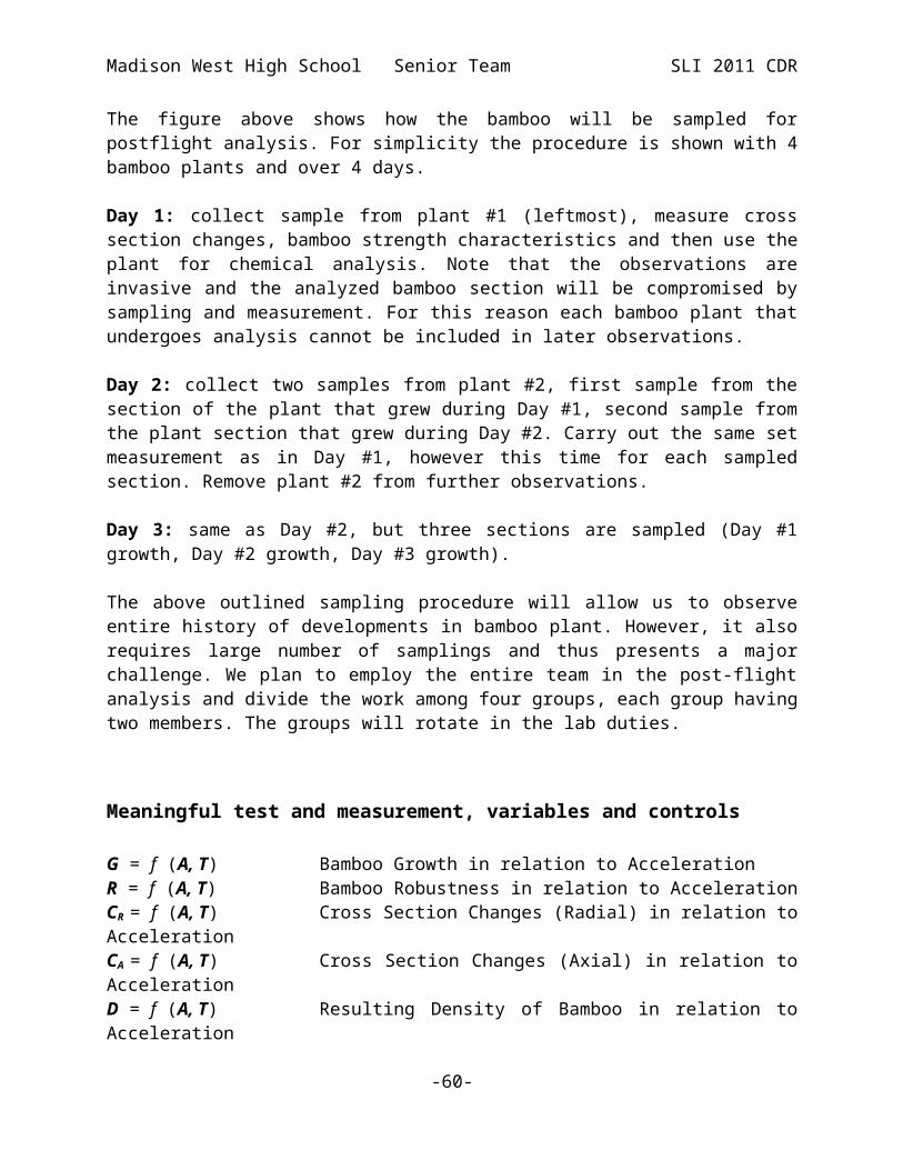
Figure 20: Sampling of bamboo for postflight analysis.
The figure above shows how the bamboo will be sampled for postflight analysis. For simplicity the procedure is shown with 4 bamboo plants and over 4 days.
Day 1: collect sample from plant #1 (leftmost), measure cross section changes, bamboo strength characteristics and then use the plant for chemical analysis. Note that the observations are invasive and the analyzed bamboo section will be compromised by sampling and measurement. For this reason each bamboo plant that undergoes analysis cannot be included in later observations.
-46-
Madison West High School Senior Team SLI 2011 CDR
Day 2: collect two samples from plant #2, first sample from the section of the plant that grew during Day #1, second sample from the plant section that grew during Day #2. Carry out the same set measurement as in Day #1, however this time for each sampled section. Remove plant #2 from further observations.
Day 3: same as Day #2, but three sections are sampled (Day #1 growth, Day #2 growth, Day #3 growth).
The above outlined sampling procedure will allow us to observe entire history of developments in bamboo plant. However, it also requires large number of samplings and thus presents a major challenge. We plan to employ the entire team in the post-flight analysis and divide the work among four groups, each group having two members. The groups will rotate in the lab duties.
Meaningful test and measurement, variables and controls
G = f (A, T) Bamboo Growth in relation to AccelerationR = f (A, T) Bamboo Robustness in relation to AccelerationCR = f (A, T) Cross Section Changes (Radial) in relation to AccelerationCA = f (A, T) Cross Section Changes (Axial) in relation to AccelerationD = f (A, T) Resulting Density of Bamboo in relation to Acceleration
Test and Measurement, Variables and Controls
Test Specific Measurements following abovementioned methods
Bamboo Growth Length measurements on bamboo will be made every day for three weeks
Bamboo Robustness Break strength meter will measure robustness
Radial Cross Section changes We will quantify details from microscope analysis of bamboo cross sections (radial)
Axial Cross Section changes We will quantify details from microscope analysis of bamboo cross sections (axial)
Density of bamboo Weight and volume measurements taken every day for many weeks
Table 21: Test and Measurement, Variables and Controls
-47-

Madison West High School Senior Team SLI 2011 CDR
Independent Variables
A AccelerationT Age of plant
Dependent Variables
G Bamboo growthR Bamboo robustnessCR and CA Changes in cross section (radial and axial)D Resulting plant density
Constants Light Exposure Bamboo Specimen Growing Conditions Testing Methods Bamboo Orientation in Payload Chambers
Relevance of expected data, along with an accuracy/error analysis, including tables and plots
The correlations that can be made from our experiment can help us better understand
the healing of fargesia fungosa plants from hypergravity-induced damage. The change in cell structure as a result in the healing process may cause increased strength in the bamboo. As an alternative and green building material, knowledge of how the structural strength of bamboo can be increased is relevant. All of the seedlings will be planted and grown in environmentally controlled chambers. The bamboo species, growing conditions, testing methods, and acceleration on the bamboo will remain constant throughout the payload.
To ensure the accuracy of our experiment, there will be two redundant environmental chambers for each orientation and acceleration. There will also be control groups which will remain grounded and will be tested with the same procedures as the fargesia fungosa that was flown. Tests will be performed on the plants on a daily basis to monitor the changes in the fargesia fungosa.
Provide detailed experiment process procedures. To prepare the soil mixture for successful growth of the fargesia fungosa seedlings, it will first be mixed in a 40:40:20 mixture of sand, silt, and clay respectively from its constituent components by hand. Then, the soil will be measured out into portions for each environmental chamber; it will also be moistened at this stage. The bamboo will be
-48-

Madison West High School Senior Team SLI 2011 CDR
planted in the soil and allowed to grow for approximately one week. After growth, the chambers will be fully sealed and the samples will be flown.
The mechanical system will be assembled before the biological system is planted within it, allowing the soil mixture (loam) to conform to the shape of the containers in which it will be housed, with minimal root disruption that would come with re-potting. The mechanical system is made entirely from synthetic materials and stainless steel to allow for the moisture that will inevitably accumulate during the watering and growth of the bamboo seedlings.
The electronics system will not be attached to the mechanical system until just before flight. This is to prevent risk of corrosion from atmospheric moisture. Just prior to the sealing of the environmental chambers for the flight, the satellite boards will be installed on the inter-payload bulkheads and the master board installed on the top bulkhead. Then electronics tests will be run on all connections prior to flight.
-49-

Madison West High School Senior Team SLI 2011 CDR
Data Acquisition
See Monitoring Components System
Experiment Design of Payload
Review the design at a system level, describe integration plan, and demonstrate that the design can meet all mission goals.Designed as independent units, each Environmental Chamber studies the effect of hypergravity on Fargesia Fungosa seedlings based on its assigned orientation. For redundancy, we have included four chambers in both the booster and the sustainer, two of each orientation. Other than the Agar Containment Unit in the Horizontally Positioned Bamboo Chamber, each chamber design consists of the same systems: a Mechanical System, Biological System, Data Process and Storage System, Monitoring Components System.
Robust and weight-efficient, the Mechanical System provides adequate protection to the vital components inside, while adhering to the weight constraint imposed by the vehicle team. Materials were chosen because of availability and low costs; furthermore, the clear acrylic tubing will let us view the interior of the chamber at all time.
The bamboo species—a Biological System component—was a difficult choice. Of the problems we encountered while choosing the species, finding an available plant store caused the most distress. It was difficult enough to find a small plant type that would fit in our rocket, but finding a store that sold it in our area was even harder. We eventually chose Fargesia Fungosa because of the price, and ordered it from a German plant store online.
Both the Data Process and Storage System and the Monitoring Components System were chosen based on previous experience with experiments that require electronics. To simplify our subsystem organizations, we divided the electronic elements into these basic categories.
Payload SystemsOur payload consists of three major systems: the Mechanical System, The Biological System, Data Processing and Storage System, Monitoring Components System.
-50-

Vessel
Inter-Payload Bulkhead
Madison West High School Senior Team SLI 2011 CDR
Mechanical SystemThe Mechanical System is the containment system for our payload. This system helps control the experiment. Each Environmental Chamber includes a Vessel, which holds the Biological System. At the end of each Vessel is an Inter-Payload Bulkhead. The Vessel will fit between the bulkheads and there will be tie-rods running through the bulkheads to fix the vessel in place.
Figure 21: Mechanical System of our Environmental Chamber
-51-

Madison West High School Senior Team SLI 2011 CDR
Figure 22: Payload bulkhead designed in Autodesk
Subsystem Function Accuracy/Precision Requirements
VesselA 2.50 inch acrylic tube, the vessel will contain the Biological System of our payload.
N/A
Inter-Payload Bulkheads
These bulkheads will be the transition between each Environmental Chamber. The Vessels will fit into the bulkheads and attached using tie-rods. The electrical system will also be attached to the bulkheads.
We will print these bulkheads using 3-D printers to ensure that all components will attach correctly.
Table 22: Subsystems of the Mechanical System
-52-

Loam
Bamboo
Loam Containment Unit
Madison West High School Senior Team SLI 2011 CDR
Biological SystemThe Biological System of our payload includes loam, Fargesia Fungosa (Bamboo Seedling), and the Loam Containment Unit. The Loam Containment Unit is used exclusively for the horizontally growing bamboo. Loam is a soil mixture containing sand, silt and clay. It will contain all the necessary nutrients and be of a sufficient density to go through the gravitational forces generated during flight. The bamboo will be grown to a specific age before being flown.
Figure 23: Biological System of the Environmental Chamber
-53-

Madison West High School Senior Team SLI 2011 CDR
Subsystem Function Accuracy/Precision Requirements
Loam
We will grow our Bamboo seedlings in the loam. The Loam will provide nutrients for the bamboo during the entire growth cycle.
Consistency of the loam in terms of nutrients and density.
Fargesia Fungosa (Bamboo Seedling)
Bamboo seedlings will be planted in the loam. Once they are a week old, the bamboo seedlings will be flown in our vehicle.
Bamboo seedlings will be grown to the correct age.
Loam Containment Unit
This will be used specifically for the horizontally growing bamboo. This vessel will contain the loam and bamboo.
N/A
Table 23: Subsystems of the Biological System
Data Processing and Storage SystemThe Data Processing and Storage System involves storage of data collected from the satellite boards as well as the various miscellaneous items required for the successful functioning of electronics.
Subsystem Function Accuracy/Precision EEPROM Programs the CPU 24LC1025, 128kBCable and Data Transfer Transfer data from satellite
board to central board N/A
Power Source Powers the electronics 8 x 1.5AA battery packG-Switch Start collecting data after
liftoff 2g activation force
Power Regulators Provide clean 5.00V and 3.30V power source LS1085, LT1461
ADC (Analog to Digital Convertor)
Converts the analog to a digital signal
16bit, 3kSps
CPU (Central Processing Unit)
Initiates the reaction, collects the temperature profiles and controls the fans
A Parallax Propeller Chip, 8 cores, 80MHz clock, 32 kB RAM
Memory Stores Data Atmel AT26/25 flash memory, 2MB
Table 24: Subsystems of the Data Processing and Storage System
-54-

Madison West High School Senior Team SLI 2011 CDR
Figure 24: Left: The central flight computer includes the G-Switch, EEProm, ADC, Power Convertor, Buzzer, Memory and connectors. Right: The layout of central flight computer and satellite payload controllers.
-55-
Madison West High School Senior Team SLI 2011 CDR
Figure 25: Central Board's high-level schematic
Monitoring Components System
The Monitoring Components system records data from the various Environmental Chambers. It collects temperature, humidity and light sensor data. It also provides power for the light source for constant lighting in the environmental chambers.
Subsystem Function Accuracy/Precision
Cable and Data Transfer Transfer data from satellite board to central board N/A
Temperature SensorStarts collecting data after liftoff
Thermistor measures to 0.1 of a degree, sampled 1 time a second
Humidity SensorStarts collecting data after liftoff
Humidity sensor measures to 0.1 percent, time a second
Light Sensor Detects the light intensity in payload TSL230
Light Source Keeps constant lighting in payload N/A
Table 25: Subsystems of the Monitoring Components System
Design meets system level functional requirements
System Subsystems Performance Characteristics
Mechanical System
1. Vessel2. Inter-Payload
Bulkhead
1. Adequately contains Biological System
2. Reliably isolates and separates each chamber
3. Reliably holds Electronics in place
4. Manages experiment variables
Biological System 1. Loam2. Fargesia Fungosa
(Bamboo Seedlings)3. Loam Containment
Unit
1. Supports seedling position
2. Must withstand gravitational forces generated by rocket flight
3. Reliably provide equal nutrition to all bamboo
4. Keeps loam from
-56-
Madison West High School Senior Team SLI 2011 CDR
moving excessively throughout entire flight
Data Processing and Storage System
1. Master Flight Computer Storage Subsystem
2. Cable and Data Transfer
3. Power Source
1. Stores data reliably, low data corruption rate
2. Transfers data correctly, high signal to noise ratio
Monitoring Components System
1. Temperature Sensor2. Humidity Sensor3. Light Sensor4. Light Source5. Cable and Data
Transfer
1. Reliably monitors temperature, light, and humidity inside chambers
2. Provides consistent and regular lighting
3. Transfers data correctly, high signal to noise ratio
Table 26: Performance Characteristics of each Systems and subsystems
Provide information regarding the precision of instrumentation and repeatability of measurement.Please refer back to the Payload Subsystem section for the precision of instrumentation.
Our payload is designed for easy repetition of the experiment. The payload components are linked together in such a way that removal from and insertion into the rocket does not require significant effort or altering of the payload, meaning that the experiment is easily repeatable. Additionally, the payload modules do not require any kind of altering to remove the bamboo specimens, thus allowing us to repeat the experiment without having to re-build the payload modules.
-57-
Madison West High School Senior Team SLI 2011 CDR
Verification MatrixThe components and tests for the verification matrix are listed below.Verification Test
1. Drop Test: Drop components to ensure that they will not break in flight or during landing. Drop height will be chosen so that it simulates a rocket landing.
2. Connection and Basic Functionality Test: Ensure that all electronic components, devices and batteries are connected firmly and will not loosen in flight. When possible verify that powered up component functions correctly.
3. Pressure Chamber Test: We will place the altimeter in a chamber to make sure the altimeter registers the correct pressure
4. Temperature and Humidity Sensor Test: Place sensors in a known setting—in terms of temperature and humidity level—to verify that they register the correct values.
5. Durability Test: Verify that the various components will not detach during flight.6. Battery Capacity Test: Verify that our batteries will supply enough power for our
electronics to function for a sufficient time (at least one hour).7. Final Test: Test the complete subsystem for its function.
P=PlanedF=Finished
1 2 3 4 5 6 7
Vessel P P PInter-Payload Bulkhead F F F PLoam F F F FFargesia Fungosa (Bamboo Seedlings) F F F F FLoam Containment Unit P P P PMaster Flight Computer Storage Subsystem F F F F F F FCable and Data Transfer P P P P P PPower Source F F F F F FTemperature Sensor F F F F F FHumidity Sensor F F F F F FLight Sensor F F F F F FLight Source F F F F F
Table 27: Verification Matrix of the Payload
The payload is currently being designed and developed and as of now no components were made ready for testing.
-58-

Madison West High School Senior Team SLI 2011 CDR
Application of engineering, functionality, and feasibility.Each payload module is designed with the success criteria in mind. The modules are made to work easily with each system and subsystem. The Biological, Mechanical and Electronic systems each correspond with each other. Please refer to the Experimental Design of the Payload and Assembly section of the document.
Flight performance predictions (Payload)During the first two seconds the bamboo will first experience a mild acceleration of approximately 8 Gees, then a high acceleration of approximately 30 Gees. The high acceleration as well as high rate of change for acceleration, jerk, will cause damage to the bamboo and change the cell structure and growth patterns.
Flight preparation procedures (Payload)1. Grow the bamboo in both the horizontal and vertical orientations2. Activate various sensors prior to flight3. Clamp each environmental chambers between the Inter-payload Bulkheads4. Secure the tie-rods5. Slide into the vehicle.6. Install exterior vehicle screws to secure payload
Specify approach to workmanship as it relates to mission success.Our meetings are held twice weekly, with all members and mentors present. Dedicated sub teams exist for. There is a lot of communications between the four groups. We have a dynamic bond between team members and mentors which enables us to work efficiently and precisely.
Discuss completed component, functional, or static testingWe have a series of planned testing regarding the payload and its components. These tests will be discussed in the Verification Matrix.
-59-
Madison West High School Senior Team SLI 2011 CDR
Assembly
Clear details of how the rocket is assembled.
Each payload module consists of an Environmental Chamber—either a horizontally oriented or vertically oriented one. Regardless, both types will include the same components: Inter-Payload Bulkhead, Loam, Fargesia Fungosa (Bamboo Seedling), electronics, and sensors. However, a Loam Containment Unit exists in the horizontally oriented Environmental Chamber to situate the Loam.A clear acrylic Vessel holds the Bamboo Seedlings inside the Loam (and the Loam is held in place by the Loam Containment Unit). At each end of the Vessel, the Inter-Payload Bulkheads separate each Environmental Chamber. The sensors—temperature, humidity, and light—are at one Inter-Payload Bulkhead and collect all data significant to the discrete modules. The majority of the electronics remain at one Inter-Payload Bulkhead, and wires running down the sides of the Environmental Chambers connect them.
Integration and compatibility simplicity
Figure 26: Integration of the payload into the vehicle
To investigate the effects of hypergravity on Fargesia Fungosa, we designed chambers that will hold the bamboo shoots and its aiding components. We designed similar chambers to hold the horizontal and vertical bamboo specimens. A total of eight chambers—four chambers each for horizontal and vertical bamboo—will make up the payload. The first set will fly inside the booster section; the second, inside the sustainer. Each set will be connected using tie-rods and a set of inter-payload bulkheads. Installing each set as one unit greatly reduces the complexity of the integration and increases the ease of installation.
This payload design integrates easily with the vehicle. Payload components will stay in place for the duration of rocket flight and are independent of vehicle subsystems. The payload meets size and weight constraints imposed by the vehicle, and will be able to withstand the stresses of rocket flight. This design will allow easy installation and removal of the payload.
-60-

Madison West High School Senior Team SLI 2011 CDR
Structural integrity for flight
The payload modules, consisting of polycarbonate bulkheads, acrylic tubing, and steel threaded rods, will have enough structural stability to withstand the rigors of flight and landing. The Loam will have the optimal density; it will not break underneath the gravitational forces. In addition, we will secure the payload modules to the vehicle using screws. This will ensure that the payload does not slide within the tube and cause damage to critical flight systems.
Quality of constructionThe quality of our payload construction is directly proportional to the quality of our results. Thus, we take the utmost care to construct our payload to the specifications necessary to carry our flight objectives. Members of our team have had extensive experience in the construction of mechanical devices and are well-versed in tool usage to ensure a workable result. During the construction of the payload, team members will take care in the construction to ensure that the final payload can function to meet mission criteria.
-61-

Madison West High School Senior Team SLI 2011 CDR
Safety and Environment (Payload)Safety Officer: Yifan LiI NAR Safety Requirements
a. Certification and Operating Clearances: Mr. Lillesand holds a Level 3 HPR certification. Dr. Pinkas has a Level 1 HPR certification and plans on having a Level 2 HPR certification by the end of February 2010. Mr. Lillesand has Low Explosives User Permit (LEUP). If necessary, the team can store propellant with Mr. Goebel, who owns a BATFE approved magazine for storage of solid motor grains containing over 62.5 grams of propellant.
Mr. Lillesand is the designated individual rocket owner for liability purposes andhe will accompany the team to Huntsville. Upon his successful L2 certification,Dr. Pinkas will become a backup person for this role.
All HPR flights will be conducted only at launches covered by an HPR waiver (mostly the WOOSH/NAR Section #558 10,000ft waiver for Richard Bong Recreation Area launch site). All LMR flights will be conducted only at the launches with the FAA notification phoned in at least 24 hours prior to the launch. NAR and NFPA Safety Codes for model rockets and high power rockets will be observed at all launches. Mentors will be present at all launches to supervise the proceedings.
b. Motors: We will purchase and use in our vehicle only NAR-certified rocket motors and will do so through our NAR mentors. Mentors will handle all motors and ejection charges.
c. Construction of Rocket: In the construction of our vehicle, we will use only proven, reliable materials made by well established manufacturers, under the supervision of our NAR mentors. We will comply with all NAR standards regarding the materials and construction methods. Reliable, verified methods of recovery will be exercised during the retrieval of our vehicle. Motors will be used that fall within the NAR HPR Level 2 power limits as well as the restrictions outlined by the SLI program. Lightweight materials such as fiberglass tubing and carbon fiber will be used in the construction of the rocket to ensure that the vehicle is under the engine’s maximum liftoff weight. The computer program RockSim will be utilized to help design and pre-test the stability of our rocket so that no unexpected and potentially dangerous problems with the vehicle occur. Scale model of the rocket will be built and flown to prove the rocket stability.
d. Payload: As our payload does not contain hazardous materials, it does not present danger to the environment. However, our NAR mentors will check the payload prior to launch in order to verify that there will be no problems.
e. Launch Conditions: Test launches will be performed at Richard I. Bong Recreation Area with our mentors present to oversee all proceedings. All launches will be carried
-62-

Madison West High School Senior Team SLI 2011 CDR
out in accordance with FAA, NFPA and NAR safety regulations regarding model and HPR rocket safety, launch angles, and weather conditions. Caution will be exercised by all team members when recovering the vehicle components after flight. No rocket will be launched under conditions of limited visibility, low cloud cover, winds over 20mph or increased fire hazards (drought).
II. Hazardous MaterialsAll hazardous materials will be purchased, handled, used, and stored by our NAR mentors. The use of hazardous chemicals in the construction of the rocket, such as epoxy resin, will be carefully supervised by our NAR mentors. When handling such materials, we will make sure to carefully scrutinize and use all MSDS sheets and necessary protection (gloves, goggles, proper ventilation etc.).
All MSDS sheets applicable to our project are available online athttp://westrocketry.com/sli2010/msds/msds2010n.html
III. Compliance with Laws and Environmental RegulationsAll team members and mentors will conduct themselves responsibly and construct the vehicle and payload with regard to all applicable laws and environmental regulations. We will make sure to minimize the effects of the launch process on the environment. All recoverable waste will be disposed properly. We will spare no efforts when recovering the parts of the rocket that drifted away. Properly inspected, filled and primed fire extinguishers will be on hand at the launch site.
IV. Education, Safety Briefings and SupervisionMentors and experienced rocketry team members will take time to teach new members the basics of rocket safety. All team members will be taught about the hazards of rocketry and how to respond to them; for example, fires, errant trajectories, and environmental hazards. Students will attend mandatory meetings and pay attention to pertinent emails prior participation in any of our launches to ensure their safety. A mandatory safety briefing will be held prior each launch. During the launch, adult supervisors will make sure the launch area is clear and that all students are observing the launch. Our NAR mentors will ensure that any electronics included in the vehicle are disarmed until all essential pre-launch preparations are finished. All hazardous and flammable materials, such as ejection charges and motors, will be assembled and installed by our NAR-certified mentor, complying with NAR regulations. Each launch will be announced and preceded by a countdown (in accordance with NAR safety codes).
V. Procedures and DocumentationIn all working documents, all sections describing the use of dangerous chemicals will be highlighted. Proper working procedure for such substances will be consistently applied, such as using protective goggles and gloves while working with chemicals such as epoxy. MSDS sheets will be on hand at all times to refer to for safety and emergency procedures. All work done on the building of the vehicle will be closely supervised by adult mentors, who will make sure that students use proper protection and technique when handling dangerous materials and tools necessary for rocket construction.
-63-

Madison West High School Senior Team SLI 2011 CDR
Educational engagement
Community Support
After seven years of the club’s existence, we are well known at various departments of the UW and many researchers are eager to work with us. During our six years of participation in SLI we have met with a number of people from various departments within the University of Wisconsin-Madison, including Professor McCammon from the department of Physics, Professor Eloranta from the department of Atmospheric Sciences, Professor Pawley from the department of Zoology, and Professors Anderson and Bonazza from the department of Mechanical Engineering. This year we have added Prof. Fernandez and Prof. Gilroy from the department of Botany, and Prof. Masson from the department of genetics.These contacts have been incredibly helpful in designing and refining our original experimental ideas and creating an experiment that will return meaningful data.
Every year we raise funds by raking leaves during autumn in local neighborhoods. We find this is an excellent way to earn the support of the community and increase our visibility. Madison West Rocket Club has received a significant amount of publicity as a result of our first place ranking in the 2009 TARC contest. Many local newspapers and news channels carried the story. The Madison Metropolitan School District Media produced a short film detailing our achievements, which helped spread our accomplishments.
The club also provides a steady stream of volunteers for public television and public radio fundraising drives. While this is not a direct display of our work or interests, it gives us the opportunity to provide public service in the name of our club. This year around 12 members of the club will be participating in Wisconsin Public Television pledge drives.
In 2009 many club members gave back to the community by helping build a fence in the local soccer park where we also happen to launch our TARC practice flights in the winter. We are currently discussing other soccer park improvements with their management.
-64-

Madison West High School Senior Team SLI 2011 CDR
Outreach ProgramsMadison West rocket club has recently cooperated with the Randall and O'Keefe to build and launch the ever-popular SELTZURN-V rockets (Alka-Seltzer powered rockets). Each club member worked one-on-one with an elementary/middle school student to help them build the rockets. Approximately 280 rockets were built and launched.
Figure 27: SELTZURN V rockets at final stages of the launch countdown
In addition, a short presentation was held to explain to the students how rocket propulsion works. Special attention was paid to hybrid AS+H2O motors and FujiFilm combustion chambers.
Figure 28: Elementary student coloring Alka-Seltzer rocket template
-65-

Madison West High School Senior Team SLI 2011 CDR
In mid-March many of our club’s members attended a major science event held for the benefits of elementary school students. This event, known as the Super Science Fair involves about one hundred elementary school students. We began our outreach with preparation, and presentations about our club’s rocketry projects, telling the students about our participation in TARC and SLI to interest them in rocketry beyond a middle school level. Afterward we helped each student to build and launch a miniature film canister rocket powered with Alka-Seltzer.
Date Event # of participantsNovember 2010 A-Class Rocket Building Session and
Launch at Allied Outreach Center15
November 2010 A-Class Rocket Launch for Wisconsin Youth organization Outreach with Elm Lawn Elementary School at Elver Park
50
December 2010 A-Class Rocket Launch at EAGLE School
15
January 2011 Alka Seltzer Rockets at Lincoln Elementary School
25
March 2011 Alka Seltzer Rockets at Franklin/Randal and O'Keefe School Super Science Saturday
280
April 2011 Pneumatic Rockets at EAGLE School 15June 2011 Lunch & Launch: Madison West
Rocketry Public Launch and Potluck50
Total Participants (estimate) 450
Table 28:Planed Outreach Programs
ConclusionThe project is on schedule and is progressing smoothly. Further vehicle tests will be conducted to obtain flight data. All lessons learned from the scale model flights and the full-scale flights yet to come will be applied to the design and safety of the rocket for its final launch in Huntsville.
We have made the travel and accommodation arrangements for our trip to Huntsville, AL.
-66-