
Summary 2G y 3G
66
Summary Architecture GSM & WCDMA Mtr. Axel Abraham Valdes Vargas
-
Upload
axel-abraham-valdes -
Category
Technology
-
view
215 -
download
6
Transcript of Summary 2G y 3G

Summary Architecture
GSM & WCDMA
Mtr. Axel Abraham Valdes Vargas

GSM
OSS
DESIGN
AIR
INTERFACE
GSM
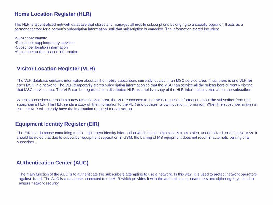
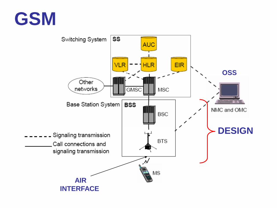
The HLR is a centralized network database that stores and manages all mobile subscriptions belonging to a specific operator. It acts as a
permanent store for a person’s subscription information until that subscription is canceled. The information stored includes:
•Subscriber identity
•Subscriber supplementary services
•Subscriber location information
•Subscriber authentication information
Visitor Location Register (VLR)
Home Location Register (HLR)
When a subscriber roams into a new MSC service area, the VLR connected to that MSC requests information about the subscriber from the
subscriber’s HLR. The HLR sends a copy of the information to the VLR and updates its own location information. When the subscriber makes a
call, the VLR will already have the information required for call set-up.
The VLR database contains information about all the mobile subscribers currently located in an MSC service area. Thus, there is one VLR for
each MSC in a network. The VLR temporarily stores subscription information so that the MSC can service all the subscribers currently visiting
that MSC service area. The VLR can be regarded as a distributed HLR as it holds a copy of the HLR information stored about the subscriber.
AUthentication Center (AUC)
The main function of the AUC is to authenticate the subscribers attempting to use a network. In this way, it is used to protect network operators
against fraud. The AUC is a database connected to the HLR which provides it with the authentication parameters and ciphering keys used to
ensure network security.
Equipment Identity Register (EIR)
The EIR is a database containing mobile equipment identity information which helps to block calls from stolen, unauthorized, or defective MSs. It
should be noted that due to subscriber-equipment separation in GSM, the barring of MS equipment does not result in automatic barring of a
subscriber.
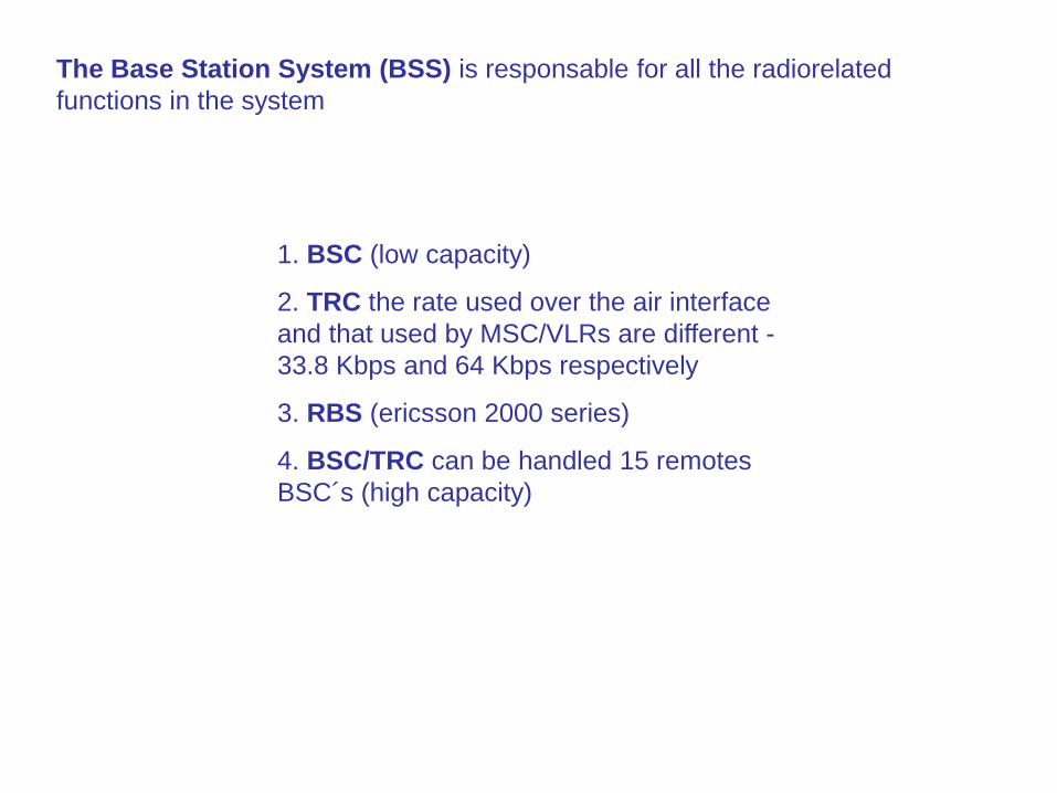
The Base Station System (BSS) is responsable for all the radiorelated
functions in the system
1. BSC (low capacity)
2. TRC the rate used over the air interface
and that used by MSC/VLRs are different -
33.8 Kbps and 64 Kbps respectively
3. RBS (ericsson 2000 series)
4. BSC/TRC can be handled 15 remotes
BSC´s (high capacity)

RADIO

Mode Term Description
Registration This is the process in which an MS
informs a network that it is attached.
Roaming When an MS moves around a network in
idle mode, it is referred to as roaming.
International
Roaming
When an MS moves into a network which
is not its home network, it is referred to as
international roaming. MSs can only roam
into networks with which the home
network has a roaming agreement.
Location
Updating
An MS roaming around the network must
inform the network when it enters a new
LA. This is called location updating.
Paging This is the process whereby a network
attempts to contact a particular MS. This
is achieved by broadcasting a paging
message containing the identity of that
MS.
Active Handover This is the process in which control of a
call is passed from one cell to another
while the MS moves between cells.
Idle

Transmission Problems
Path loss
shadowing
multipath fading
Rayleight fading
time dispersion
time alignment
Solution Problems
Interleaving
antenna diversity
space diversity
polarization diversity
adaptative equalization
frequency hopping
timing advance
use 63 bittimes (35 Km), with extended
range (70 Km) or (121 Km) using 2 TS

Rate (Kbps)
Full rate 13
Half rate 6.5
Enhanced full rate (EFR)13
Logical Channel
Control Channel
Traffic Channel
BCCH FCCH, SCH, BCCH
CCCH PCH, AGCH, RACH
DCCH SDCCH, SACCH, FACCH
Full rate and EFR
Half Rate
CHANNELS
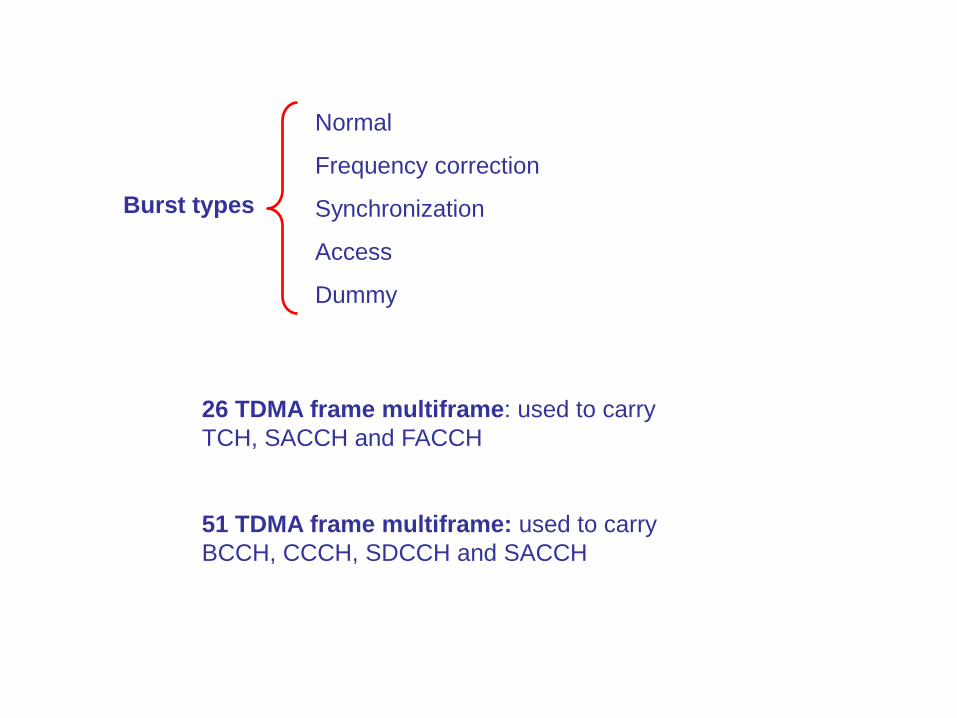
Burst types
Normal
Frequency correction
Synchronization
Access
Dummy
26 TDMA frame multiframe: used to carry
TCH, SACCH and FACCH
51 TDMA frame multiframe: used to carry
BCCH, CCCH, SDCCH and SACCH
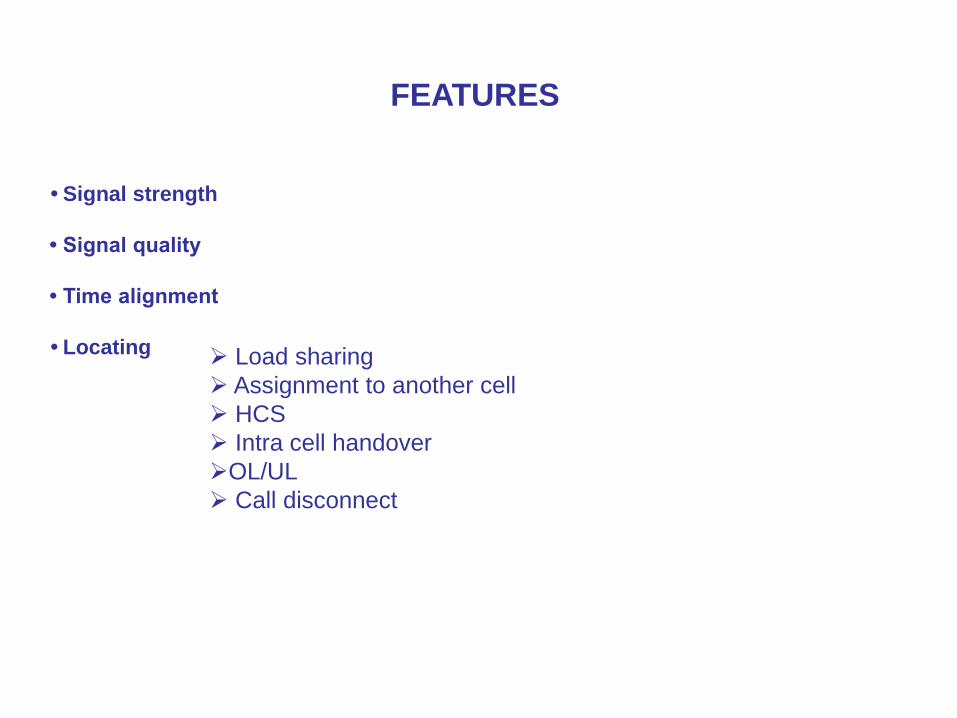
• Signal strength
• Signal quality
• Time alignment
• Locating
FEATURES
Load sharing
Assignment to another cell
HCS
Intra cell handover
OL/UL
Call disconnect

DESIGN
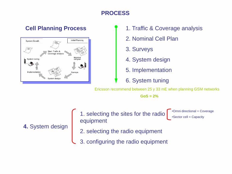
Cell Planning Process 1. Traffic & Coverage analysis
2. Nominal Cell Plan
3. Surveys
4. System design
5. Implementation
6. System tuning
Ericsson recommend between 25 y 33 mE when planning GSM networks
GoS = 2%
4. System design
1. selecting the sites for the radio
equipment
2. selecting the radio equipment
3. configuring the radio equipment
•Omni directional = Coverage
•Sector cell = Capacity
PROCESS

Adjacent frequencies C/A are the frequencies with a landslide of 200 KHz of the Carrier and
preferably also must be avoided in the same Cell and in their neighbors, so that they cause to
problems of Interference and Quality in the call.
Ericsson recommends that relation C/A in GSM is of -9 dB
Maximum radius of a GSM cell = 35 Km
Whit 2 TMA = 70 Km (large coverage and low capacity)
C/I is greater than 9 dB (ericsson recommend 12 dB)
C/A is greater than -9 dB (ericsson recommend that higher that 3 dBm) F2 = F1 + 200KHz
Plan 7/21 recommend for networks whit higher interference
4/12 4 sectors site and 12 group frequency
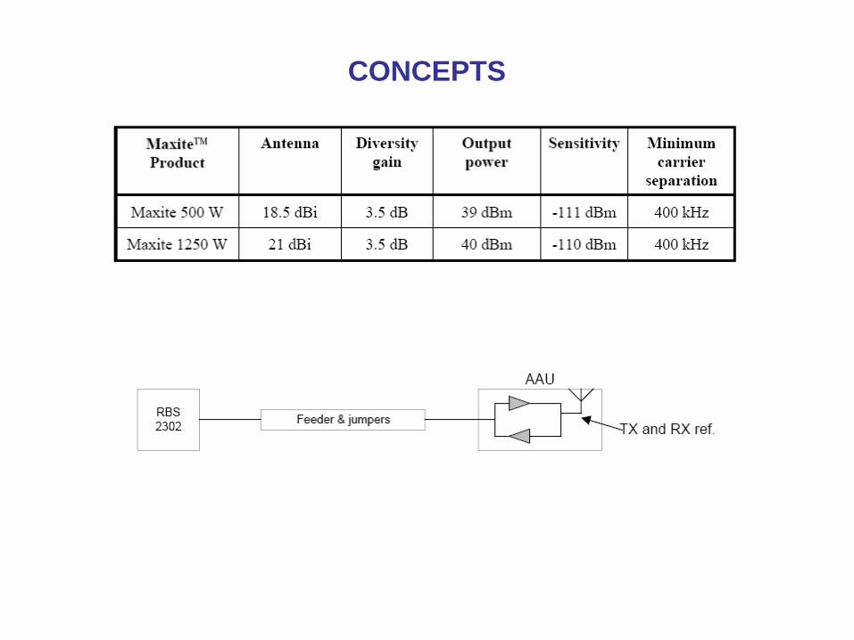
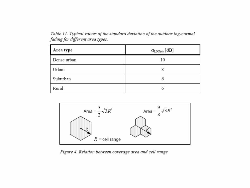
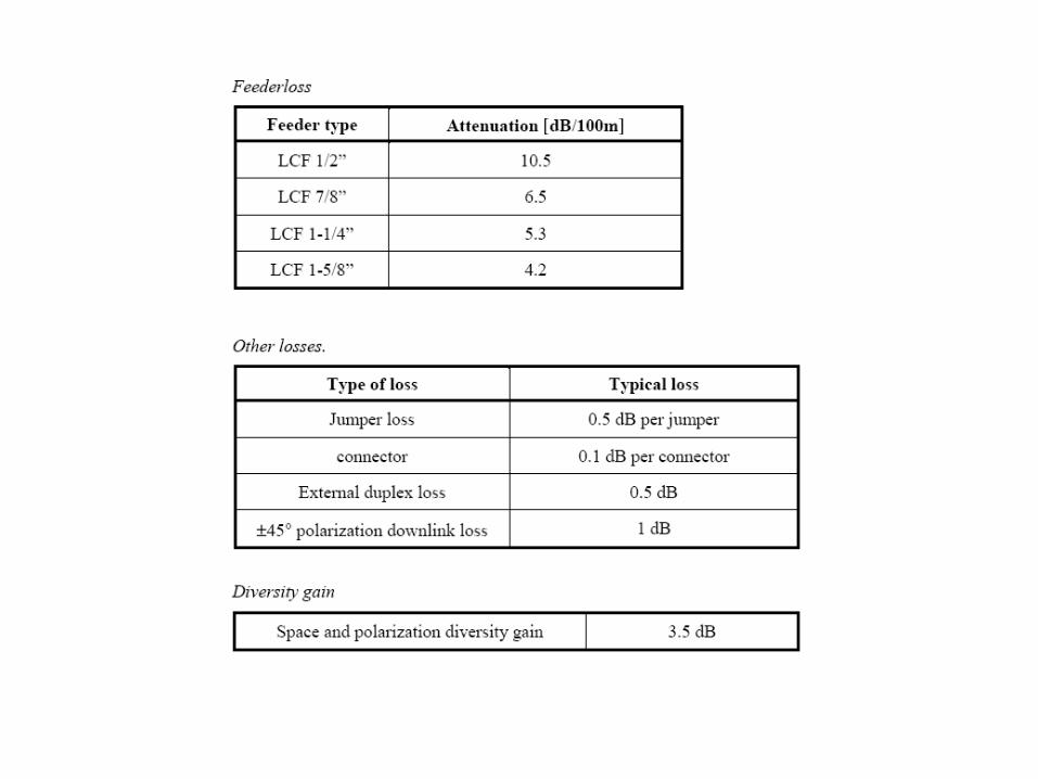
CONCEPTS
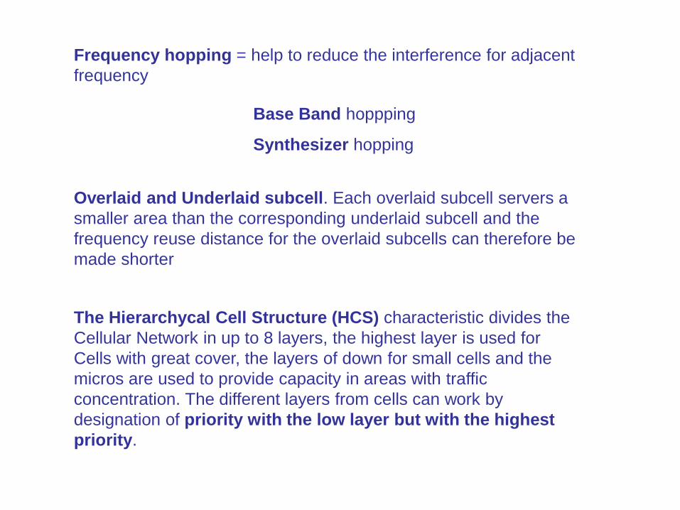
Frequency hopping = help to reduce the interference for adjacent
frequency
Overlaid and Underlaid subcell. Each overlaid subcell servers a
smaller area than the corresponding underlaid subcell and the
frequency reuse distance for the overlaid subcells can therefore be
made shorter
Base Band hoppping
Synthesizer hopping
The Hierarchycal Cell Structure (HCS) characteristic divides the
Cellular Network in up to 8 layers, the highest layer is used for
Cells with great cover, the layers of down for small cells and the
micros are used to provide capacity in areas with traffic
concentration. The different layers from cells can work by
designation of priority with the low layer but with the highest
priority.
HW
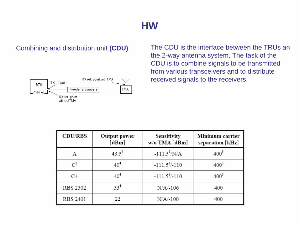
Combining and distribution unit (CDU) The CDU is the interface between the TRUs an
the 2-way antenna system. The task of the
CDU is to combine signals to be transmitted
from various transceivers and to distribute
received signals to the receivers.
CONCEPTS

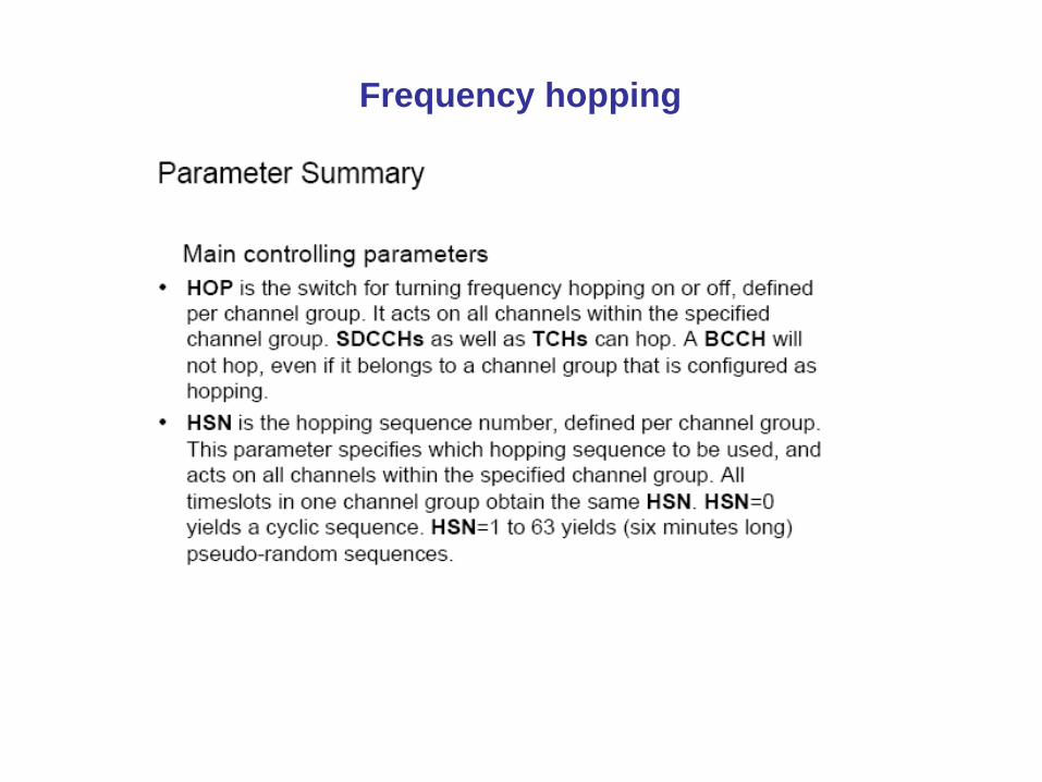
Frequency hopping
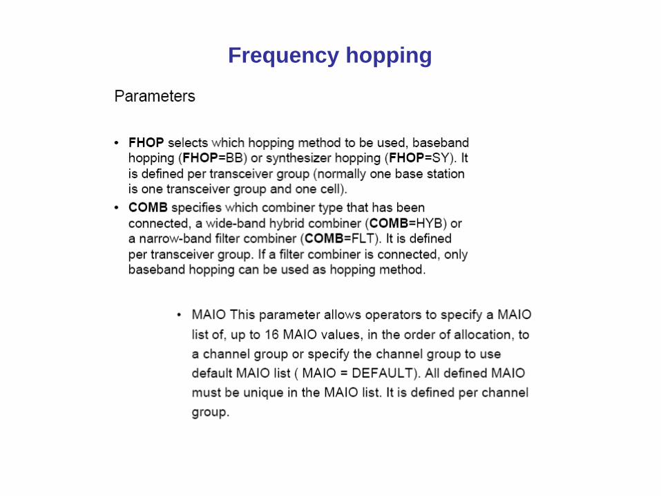
Frequency hopping

OSS
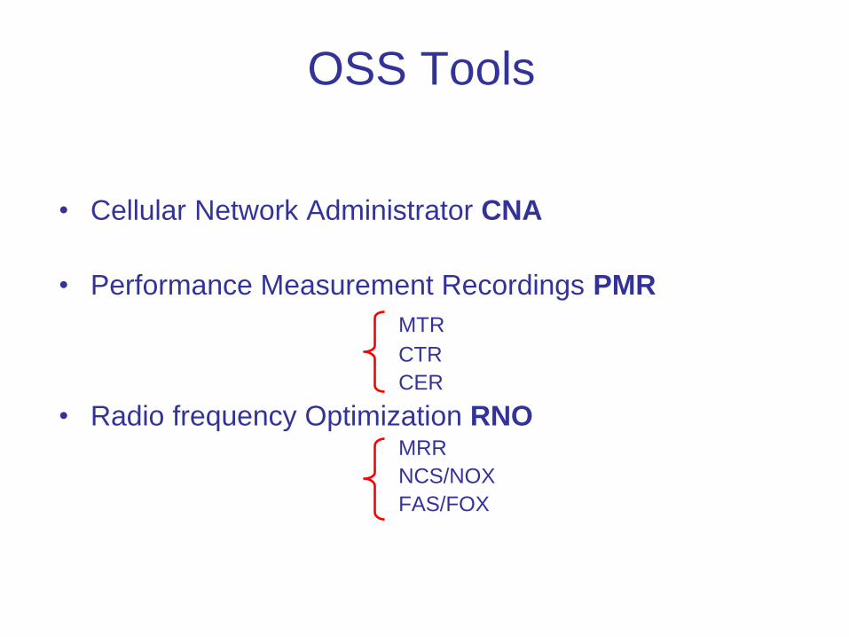
OSS Tools
• Cellular Network Administrator CNA
• Performance Measurement Recordings PMR
MTR
CTR
CER
• Radio frequency Optimization RNO MRR
NCS/NOX
FAS/FOX
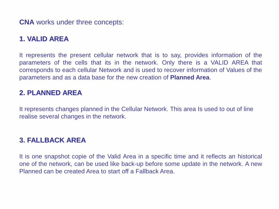
CNA works under three concepts:
1. VALID AREA
It represents the present cellular network that is to say, provides information of the
parameters of the cells that its in the network. Only there is a VALID AREA that
corresponds to each cellular Network and is used to recover information of Values of the
parameters and as a data base for the new creation of Planned Area.
2. PLANNED AREA
It represents changes planned in the Cellular Network. This area Is used to out of line
realise several changes in the network.
3. FALLBACK AREA
It is one snapshot copie of the Valid Area in a specific time and it reflects an historical
one of the network, can be used like back-up before some update in the network. A new
Planned can be created Area to start off a Fallback Area.


PMR
• MTR – mobile traffic recording
– For one or more associate MSC's as well as its BSCs
– Up to 64 IMSI’s (to level MSC)
– Independent measurements by each IMSI
– Maximum duration of 1 week
• CTR – cell traffic recording
– Events (and measurements) in a cell in particular
– Only one cell by each BSC in the same time
– Maximum duration of 1 hour

RNO
• MRR
• NCS/NOX Neighbor Optimization
• FAS/FOX Frequency Optimization
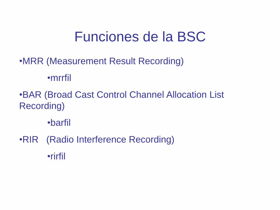
Funciones de la BSC
•MRR (Measurement Result Recording)
•mrrfil
•BAR (Broad Cast Control Channel Allocation List
Recording)
•barfil
•RIR (Radio Interference Recording)
•rirfil

WCDMA

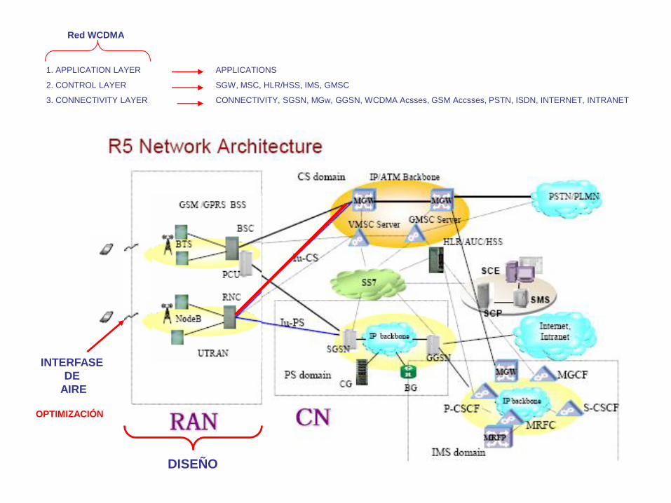
1. APPLICATION LAYER
2. CONTROL LAYER
3. CONNECTIVITY LAYER
APPLICATIONS
SGW, MSC, HLR/HSS, IMS, GMSC
CONNECTIVITY, SGSN, MGw, GGSN, WCDMA Acsses, GSM Accsses, PSTN, ISDN, INTERNET, INTRANET
Red WCDMA
DISEÑO
INTERFASE
DE
AIRE
OPTIMIZACIÓN
SERVER
MSC
SGSN
GGSN
RNC BSC/TRC
MGw
BTS Node B
WCDMA GSM
UE
Iub
Iur RNC
Uu
Iu CS
Iu PS
A-bis
Gb
A
BSC A-ter
Um
Gn

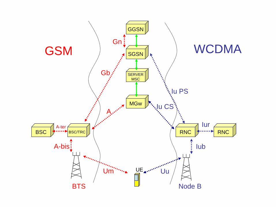
Interfaces
Iu interface = The Iu interface connects the UTRAN to the CN and is split in two
parts. The Iucs is the interface between the RNC and the circuit switched domain
of the CN. The Iups interface is the interface between the RNC and the packet
switched domain of the CN.
Uu interface = The Uu interface is the WCDMA radio interface
with in UMTS. It is the interface through which the UE accesses
the fixed part of the network.
Iub interface = The Iub interface connects the Node B and the RNC.
Iur interface = This RNC-RNC interface was initially designed in order to provide
inter RNC soft handover, but more features were added during the development.
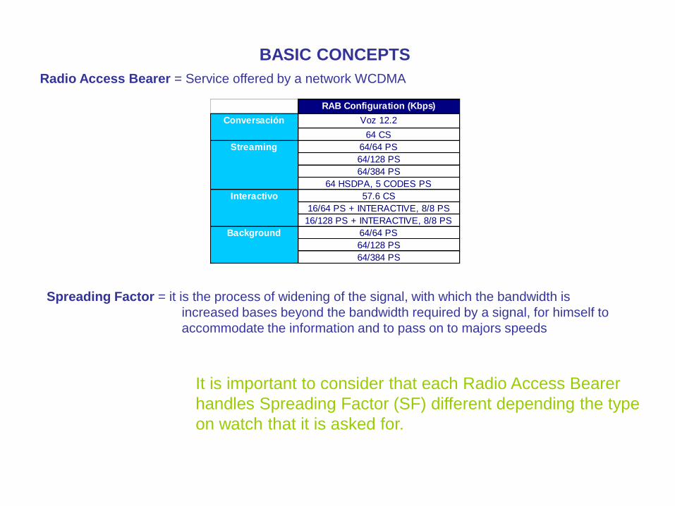
BASIC CONCEPTS
Radio Access Bearer = Service offered by a network WCDMA
RAB Configuration (Kbps)
Voz 12.2
64 CS
64/64 PS
64/128 PS
64/384 PS
64 HSDPA, 5 CODES PS
57.6 CS
16/64 PS + INTERACTIVE, 8/8 PS
16/128 PS + INTERACTIVE, 8/8 PS
64/64 PS
64/128 PS
64/384 PS
Conversación
Streaming
Interactivo
Background
Spreading Factor = it is the process of widening of the signal, with which the bandwidth is
increased bases beyond the bandwidth required by a signal, for himself to
accommodate the information and to pass on to majors speeds
It is important to consider that each Radio Access Bearer
handles Spreading Factor (SF) different depending the type
on watch that it is asked for.

Channel Element = one talks about to the resources required in node B (Hw) to provide
capacity for the services asked for by the users such as voice, data, streaming
etc…
SIZING OF NETWORK WCDMA
For the calculation of Chanel Elements used in each node B, the following
accountants take care who indicate the number to us of Links Radio
pmNoOfRadioLinksSf128
pmNoOfRadioLinksSf16
pmNoOfRadioLinksSf256
pmNoOfRadioLinksSf32
pmNoOfRadioLinksSf4
pmNoOfRadioLinksSf64
pmNoOfRadioLinksSf8
In order to obtain the number of CE the
accountant by the number of CE is due to
multiply indicated in the CE stairs

These accountants are classified by Spreading Factor and enter radiolinks that happen
between mobile and Node B in a determined period, in such a way that to obtain Channel
Elements the count is made of Radiolinks and they are related to the stairs of Channel
Elements
Channel Element Stair
Channel Element in: SF # SF #
AMR 12.2 Kbps 64 1 128 1
CS64K 16 4 32 4
PS64K 16 4 32 4
PS128 8 8 16 4
PS384 4 16 8 16
Ul Dl

Input data for the design of a network 3G
1. Equipo preliminar (RAN)
2. Naming Convention (RAN)
3. IP ranges (IP)
4. Netwok topology (Tx)
5. Conectividad (Tx)
6. Traffic Model and services to be offered
7. RF nominal plan
8. RF detailled plan
9. CORE network design: SGSN (PS), MGw (CS), OSS
(O&M)
10. Sincronization
Speech Data
Required bandwidth
Mbps
Required
bandwidth Mbps
Traffic in E by user
(mE)
Traffic in Mb by
month
Traffic in E Kbytes / hour
Model of traffic
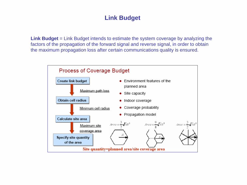
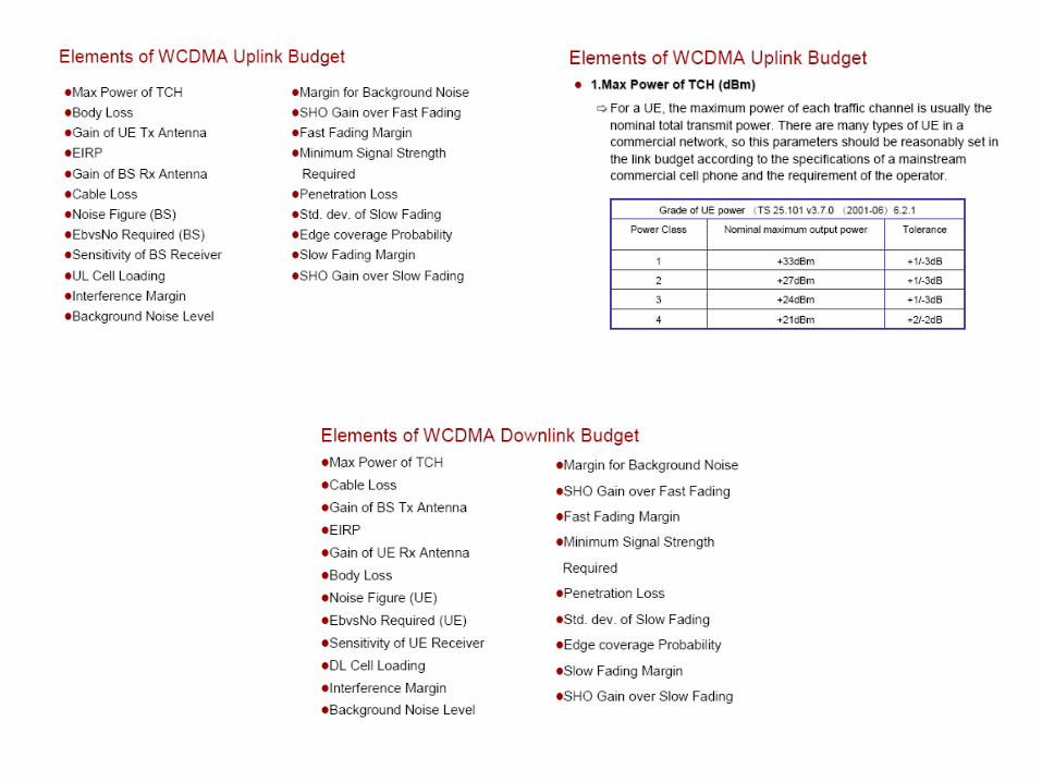
Link Budget = Link Budget intends to estimate the system coverage by analyzing the
factors of the propagation of the forward signal and reverse signal, in order to obtain
the maximum propagation loss after certain communications quality is ensured.
Link Budget
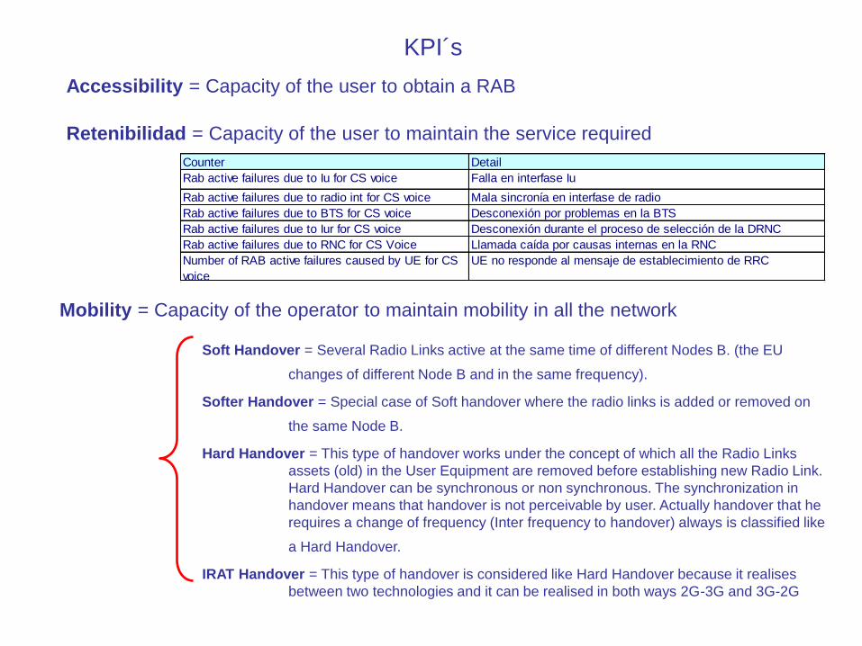
KPI´s
Accessibility = Capacity of the user to obtain a RAB
Retenibilidad = Capacity of the user to maintain the service required
Counter Detail
Rab active failures due to Iu for CS voice Falla en interfase Iu
Rab active failures due to radio int for CS voice Mala sincronía en interfase de radio
Rab active failures due to BTS for CS voice Desconexión por problemas en la BTS
Rab active failures due to Iur for CS voice Desconexión durante el proceso de selección de la DRNC
Rab active failures due to RNC for CS Voice Llamada caída por causas internas en la RNC
Number of RAB active failures caused by UE for CS
voice
UE no responde al mensaje de establecimiento de RRC
Mobility = Capacity of the operator to maintain mobility in all the network
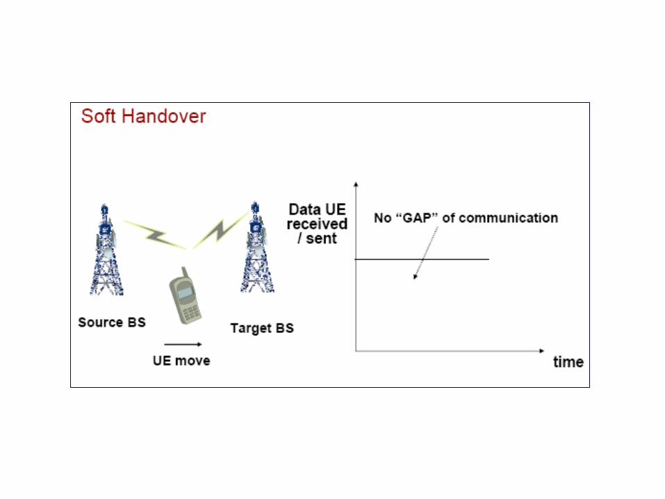
Soft Handover = Several Radio Links active at the same time of different Nodes B. (the EU
changes of different Node B and in the same frequency).
Softer Handover = Special case of Soft handover where the radio links is added or removed on
the same Node B.
Hard Handover = This type of handover works under the concept of which all the Radio Links
assets (old) in the User Equipment are removed before establishing new Radio Link.
Hard Handover can be synchronous or non synchronous. The synchronization in
handover means that handover is not perceivable by user. Actually handover that he
requires a change of frequency (Inter frequency to handover) always is classified like
a Hard Handover.
IRAT Handover = This type of handover is considered like Hard Handover because it realises
between two technologies and it can be realised in both ways 2G-3G and 3G-2G

Blocking Rate = Congestion in the cell.
CCSR (Call Completation Success Rate) = Completation of successful calls
Report Radio Measurements Detail
Received total wideband power (RTWP) Total Noise Frequency Ul UTRA in the
antenna of the cell
Transmitted carrier power Total power TX in DL in the antenna of the cell
SIR (signal to interference ratio) Signal Stregth in UL (RSCP) between the signal
and mobile and the perceived interference
(ISCP)
RSCP Received Signal Code Power, is the power of
the signal by code
SIR error Difference between the intensity of signal
measured by the RNC servant and the intensity
of signal measured by the moving body
Transmitted code power It is the transmitted power of a cell for a
dedicated physical channel (DPCH) in Dl
Chip Energy Over noise (Ec/No) He is equivalent to the intensity of signal (SIR),
but based on measurements of the pilot
channel (CPICH) Common Pilot Chanel Control
Received Signal code power It is the received power that perceives the EU
UTRA received signal strength indicator (RSSI) It is the intensity of received signal that it
perceives the EU
Node B
Dedicated Measurements
UE
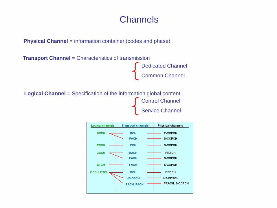
Channels
Physical Channel = information container (codes and phase)
Transport Channel = Characteristics of transmission
Dedicated Channel
Common Channel
Logical Channel = Specification of the information global content
Control Channel
Service Channel

Transport Channel = Dedicated Transport Channel
Dedicated Channel (DCH)
Common Channel Broadcast Channel (BCH)
Forward Access Channel (FACH)
Paging Channel (PCH)
Random access channel (RACH)
High-speed downlink shared channel (HS-DSCH)
Uplink
Downlink
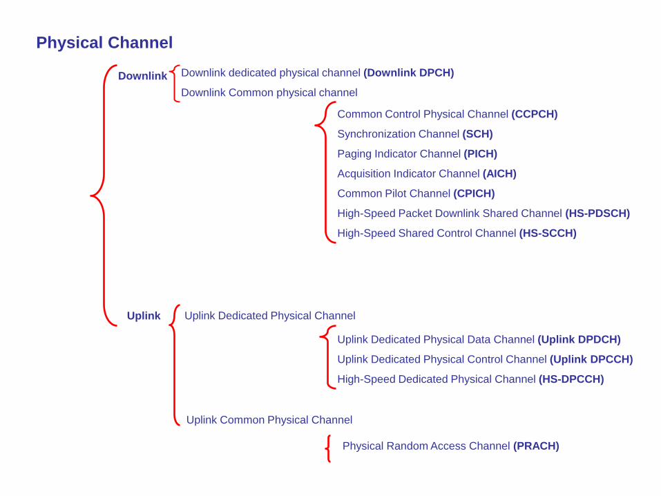
Physical Channel
Downlink
Downlink dedicated physical channel (Downlink DPCH)
Downlink Common physical channel
Common Control Physical Channel (CCPCH)
Synchronization Channel (SCH)
Paging Indicator Channel (PICH)
Acquisition Indicator Channel (AICH)
Common Pilot Channel (CPICH)
High-Speed Packet Downlink Shared Channel (HS-PDSCH)
High-Speed Shared Control Channel (HS-SCCH)
Uplink Uplink Dedicated Physical Channel
Uplink Dedicated Physical Data Channel (Uplink DPDCH)
Uplink Dedicated Physical Control Channel (Uplink DPCCH)
High-Speed Dedicated Physical Channel (HS-DPCCH)
Uplink Common Physical Channel
Physical Random Access Channel (PRACH)
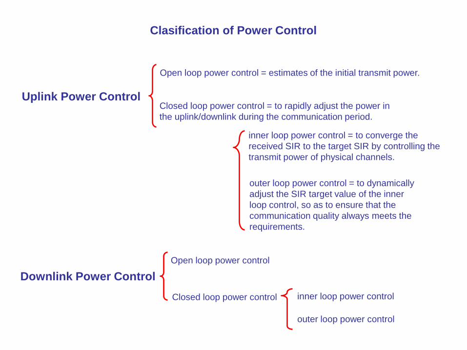
Clasification of Power Control
Uplink Power Control
Downlink Power Control
Open loop power control = estimates of the initial transmit power.
Closed loop power control = to rapidly adjust the power in
the uplink/downlink during the communication period.
inner loop power control = to converge the
received SIR to the target SIR by controlling the
transmit power of physical channels.
outer loop power control = to dynamically
adjust the SIR target value of the inner
loop control, so as to ensure that the
communication quality always meets the
requirements.
Open loop power control
Closed loop power control inner loop power control
outer loop power control

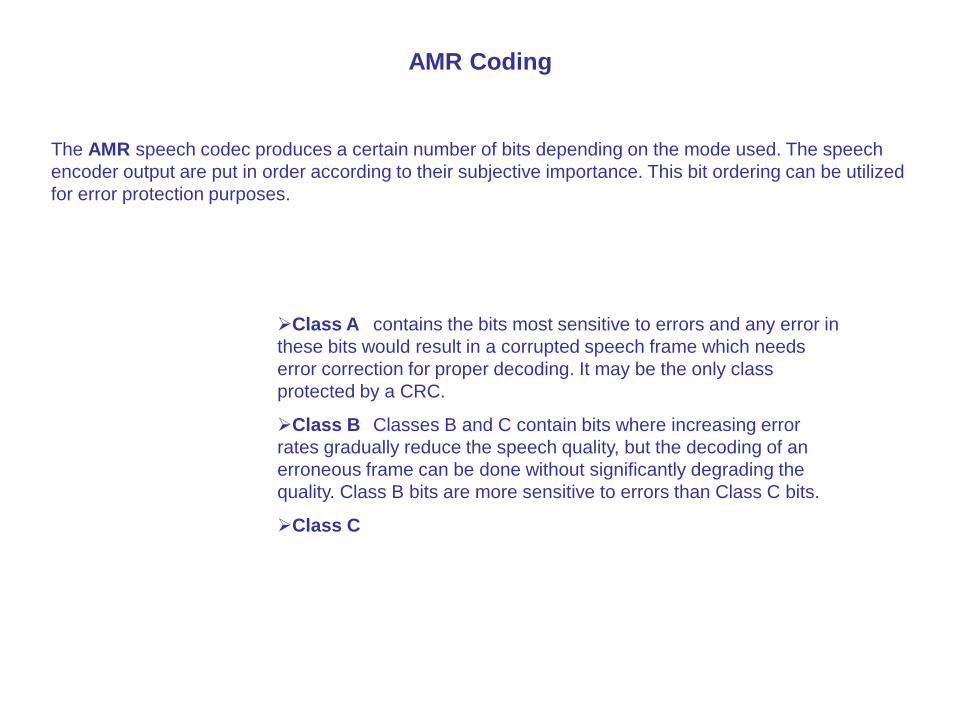
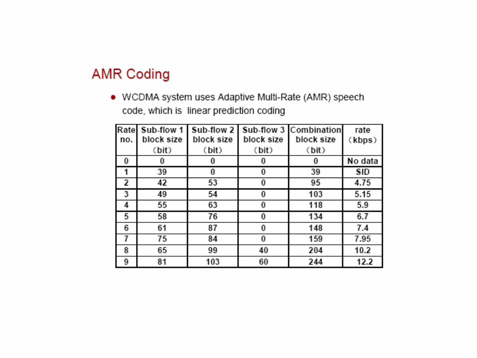
AMR Coding
The AMR speech codec produces a certain number of bits depending on the mode used. The speech
encoder output are put in order according to their subjective importance. This bit ordering can be utilized
for error protection purposes.
Class A contains the bits most sensitive to errors and any error in
these bits would result in a corrupted speech frame which needs
error correction for proper decoding. It may be the only class
protected by a CRC.
Class B Classes B and C contain bits where increasing error
rates gradually reduce the speech quality, but the decoding of an
erroneous frame can be done without significantly degrading the
quality. Class B bits are more sensitive to errors than Class C bits.
Class C
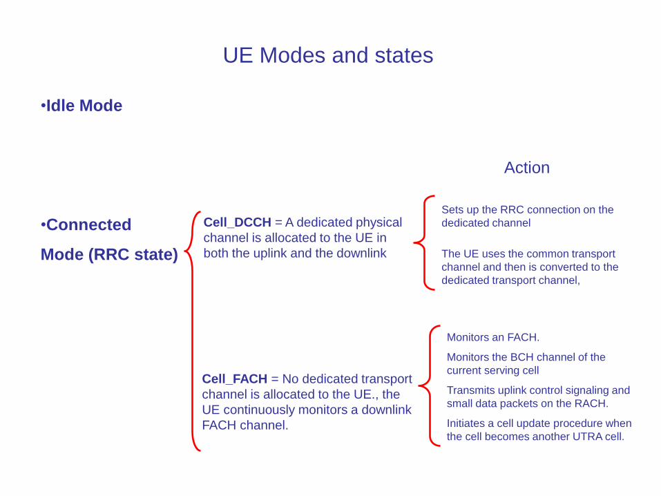
UE Modes and states
•Idle Mode
•Connected
Mode (RRC state)
Cell_DCCH = A dedicated physical
channel is allocated to the UE in
both the uplink and the downlink
Sets up the RRC connection on the
dedicated channel
Action
The UE uses the common transport
channel and then is converted to the
dedicated transport channel,
Cell_FACH = No dedicated transport
channel is allocated to the UE., the
UE continuously monitors a downlink
FACH channel.
Monitors an FACH.
Monitors the BCH channel of the
current serving cell
Transmits uplink control signaling and
small data packets on the RACH.
Initiates a cell update procedure when
the cell becomes another UTRA cell.


Cell_PCH = No dedicated channel is allocated
to the UE, the DRX technology is
adopted for the UE to monitor the
information transmitted on the PCH
channel at a specific paging time
slot.
•Monitors the paging time slot based on
the DRX period and receives the paging
messages transmitted on the PCH.
•Monitors the BCH channel of the
current serving cell
•Initiates the cell update procedure when
the cell changes.
URA_PCH = No dedicated channel is allocated to
the UE, the DRX technology is
adopted for the UE to monitor the
information transmitted on the PCH
channel at a specific paging time slot,
no uplink activity is allowed.
•Monitors the paging time slot based on
the DRX period and receives the paging
messages transmitted on the PCH.
•Monitors the BCH channel of the current
serving cell
•Initiates the URA update procedure when
the URA changes.
•No resource is allocated for data
transport in the URA_PCH state.

SHO System Handover
Active Set = Including all cells currently participating in a SHO connection of a UE
Monitored Set = Including all cells being continuously monitored by the UE and
which are not current included in its active set
Detected Set = Including the cells the UE has detected but are neither in the active set
nor in the monitored set
Process
Measurement
Decision
Execution
•Measurement Control
•Measurement execution and the result processing
•The measurement report
•Mainly accomplished by UE
Based on Measurement
The application and distribution of resource
Mainly accomplished by RRM in RNC
The process of signaling
Support the failure drawback
Measurement control refresh
Events of reporting
Intra-frequency events:1A,1B,1C,1D,1F
Inter-frequency events :2D,2F,2B,2C
Inter-system events :3A,3C
Others:6G,6F

1A A primary pilot channel enters the reporting range. When the active set of UE is full, UE stops reporting 1A
event.
1B A primary pilot channel leavels the reporting range.
1C The primary pilot channel in a non active set is better than the primary pilot channel in an active set
1D The best cell change
1E The measurement value of a primary pilot channel exceeds the absolute threshold
1F The measurement value of a primary pilot channel is lower than the absolute threshold
Intra-frequency events
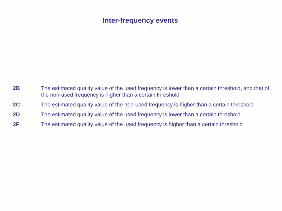
2B The estimated quality value of the used frequency is lower than a certain threshold, and that of
the non-used frequency is higher than a certain threshold
2C The estimated quality value of the non-used frequency is higher than a certain threshold
2D The estimated quality value of the used frequency is lower than a certain threshold
2F The estimated quality value of the used frequency is higher than a certain threshold
Inter-frequency events
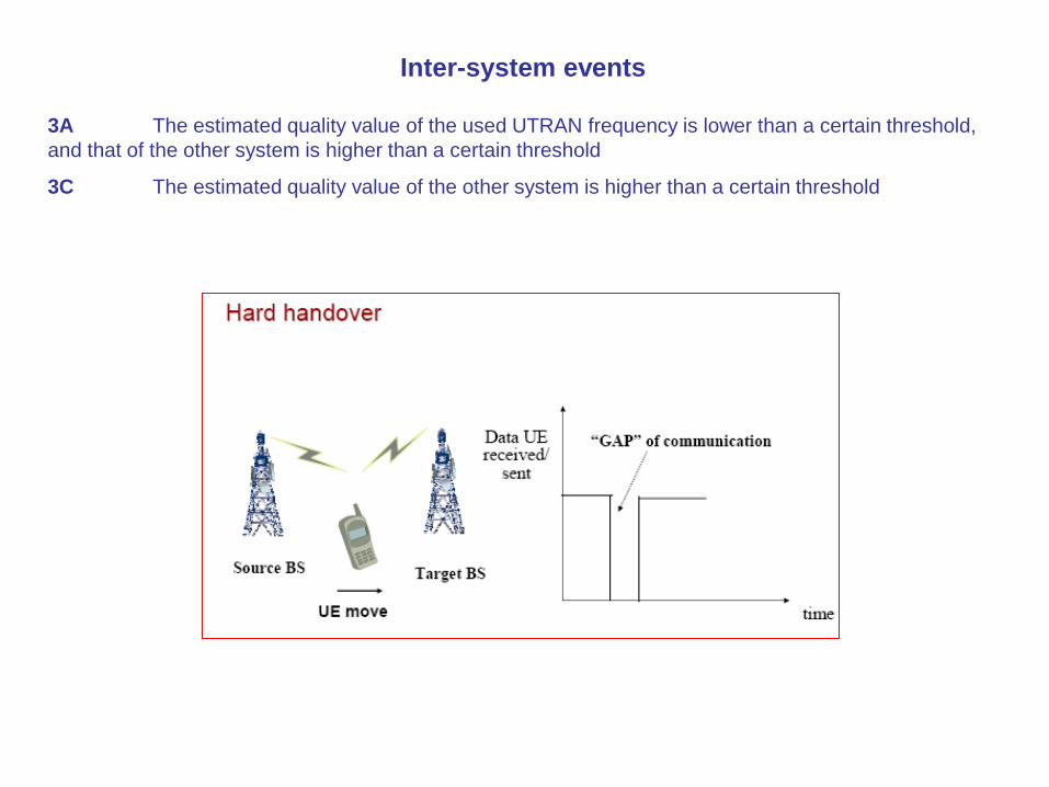
3A The estimated quality value of the used UTRAN frequency is lower than a certain threshold,
and that of the other system is higher than a certain threshold
3C The estimated quality value of the other system is higher than a certain threshold
Inter-system events

6G The time difference between downlink receiving and uplink transmission of the UE is shorter
than an absolute threshold
6F The time difference between downlink receiving and uplink transmission of the UE is bigger
than an absolute threshold
Others
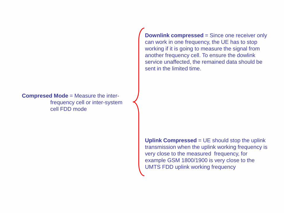
Compresed Mode = Measure the inter-
frequency cell or inter-system
cell FDD mode
Downlink compressed = Since one receiver only
can work in one frequency, the UE has to stop
working if it is going to measure the signal from
another frequency cell. To ensure the dowlink
service unaffected, the remained data should be
sent in the limited time.
Uplink Compressed = UE should stop the uplink
transmission when the uplink working frequency is
very close to the measured frequency, for
example GSM 1800/1900 is very close to the
UMTS FDD uplink working frequency

SRNC/DRNC SRNC and DRNC are on a per connection basis
between a UE and the UTRAN
The SRNC handles the connection to one UE, and
may borrow radio resources of a certain cell from the
DRNC
Drift RNSs support the Serving RNS by providing
radio resources
A UE in connection state has at least one and only
one SRNC, but can has 0 or multiple DRNCs
CRNC The CRNC owns the radio resources of a cell
Dynamical control of power for dedicated channels,
within limits admitted by CRNC, is done by the SRNC.
Scheduling of data for dedicated channels is done by
the SRNC, while for common channels it is done by the
CRNC

Optimization
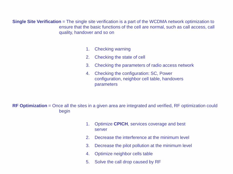
Single Site Verification = The single site verification is a part of the WCDMA network optimization to
ensure that the basic functions of the cell are normal, such as call access, call
quality, handover and so on
1. Checking warning
2. Checking the state of cell
3. Checking the parameters of radio access network
4. Checking the configuration: SC, Power
configuration, neighbor cell table, handovers
parameters
RF Optimization = Once all the sites in a given area are integrated and verified, RF optimization could
begin
1. Optimize CPICH, services coverage and best
server
2. Decrease the interference at the minimum level
3. Decrease the pilot pollution at the minimum level
4. Optimize neighbor cells table
5. Solve the call drop caused by RF
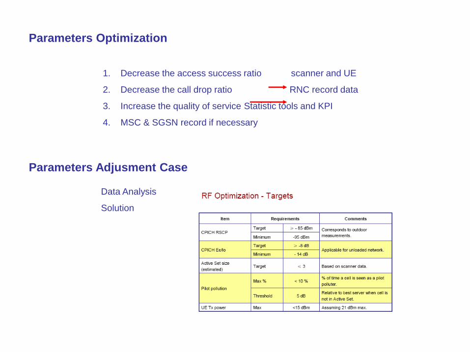
Parameters Optimization
1. Decrease the access success ratio scanner and UE
2. Decrease the call drop ratio RNC record data
3. Increase the quality of service Statistic tools and KPI
4. MSC & SGSN record if necessary
Parameters Adjusment Case
Data Analysis
Solution
GSM
Vs
WCDMA
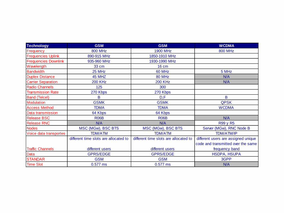
Technology GSM GSM WCDMA
Frequency 800 MHz 1900 MHz 800 MHz
Frequencies Uplink 890-915 MHz 1850-1910 MHz
Frequencies Downlink 935-960 MHz 1930-1990 MHz
Wavelength 33 cm 16 cm
Bandwidth 25 MHz 60 MHz 5 MHz
Duplex Distance 45 MHZ 80 MHz N/A
Carrier Separation 200 KHz 200 KHz N/A
Radio Channels 125 300
Transmission Rate 270 Kbps 270 Kbps
Band (Telcel) B D,F B
Modulation GSMK GSMK QPSK
Access Method TDMA TDMA WCDMA
Data transmission 64 Kbps 64 Kbps
Release BSC R06B R06B N/A
Release RNC N/A N/A R99 y R5
Nodes MSC (MGw), BSC BTS MSC (MGw), BSC BTS Server (MGw), RNC Node B
Voice data transportes TDM/ATM TDM/ATM TDM/ATM/IP
Traffic Channels
different time slots are allocated to
different users
different time slots are allocated to
different users
different users are assigned unique
code and transmitted over the same
frequency band
Data GPRS/EDGE GPRS/EDGE HSDPA, HSUPA
STANDAR GSM GSM 3GPP
Time Slot 0.577 ms 0.577 ms N/A
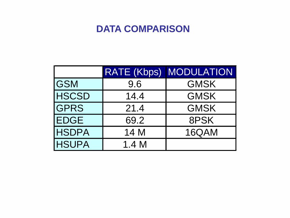
RATE (Kbps) MODULATION
GSM 9.6 GMSK
HSCSD 14.4 GMSK
GPRS 21.4 GMSK
EDGE 69.2 8PSK
HSDPA 14 M 16QAM
HSUPA 1.4 M
DATA COMPARISON


