Sumitomo Drive Technologies Sales Office Benelux Italy ... · World headquarters Sumitomo Heavy...
271
CATALOGUE I 991091 - 10/2007 CYCLO DRIVE 6000 Gearmotors & Speed Reducers Getriebemotoren & Getriebe
Transcript of Sumitomo Drive Technologies Sales Office Benelux Italy ... · World headquarters Sumitomo Heavy...

World headquarters
Sumitomo Heavy Industries Ltd.PTC GroupThinkPark Tower, 1-1, Osaki 2-chome,Shinagawa-ku, Tokyo 141-6025Japan
www.cyclo.shi.co.jp
Headquarters & ManufacturingEUROPE
Sumitomo Drive TechnologiesSumitomo (SHI) Cyclo Drive Germany GmbHCyclostraße 9285229 Markt IndersdorfGermanyTel: +49 (8136) 66 -0Fax: +49 (8136) 57 71
email: [email protected]
Sales Offices & Assembly Centres in Europe
Sumitomo Drive TechnologiesSM-Cyclo UK LimitedUnit 29, Bergen Way, Sutton Fields Industrial EstateKingston upon HullHU7 0YQ, East Yorkshire
Great BritainTel: +44 (0) 1482 790340Fax: +44 (0) 1482 8790321
Sumitomo Drive TechnologiesSM-Cyclo Scandinavia ABFöretagsvägen 30AS-23237, Arlov
SwedenTel: +46 (40) 43 02 20Fax: +46 (40) 43 10 01
Sumitomo Drive TechnologiesSales Office Benelux Heikneuterlaan 23 B-3010 Kessel-Lo/Leuven
BelgiumTel: +32 ( 016) 60 8 3 11Fax: +32 (016) 57 16 39
Headquarters & ManufacturingUSA
Sumitomo Drive TechnologiesSumitomo Machinery Corp. of America4200 Holland BoulevardChesapeake, VA 23323USATel: +1 (757) 4 85 33 55Fax: +1 (757) 4 87 31 93
www.smcyclo.com
Sumitomo Drive TechnologiesSM-Cyclo France 65-75 Avenue Jean MermozEspace Primagaz, 93126 La Courneuve
FranceTel: +33 (1) 49 92 94 94Fax: +33 (1) 49 92 94 90
Sumitomo Drive TechnologiesSM-Cyclo Italy S.R.LVia dell' Artigianato 2320010 Cornaredo (MI)
ItalyTel: +39 (02) 93 56 21 21Fax: +39 (02) 93 56 98 93
Sumitomo Drive TechnologiesSM-Cylo IberiaEdificio Gobelas C/Landabarri no4 Escalera1 2o izqda, Leioa48940 Vizcaya
SpainTel: +34 (94) 48 05 38 9Fax: +34 (94) 48 01 55 0
Worldwide locations
Sumitomo (SHI) Cyclo Drive Germany, GmbH
CCYY
CCLLOO
DDRR
IIVVEE
6600
0000
CATALOGUE I 991091 - 10/2007
CCYYCCLLOO DDRRIIVVEE 66000000GGeeaarrmmoottoorrss && SSppeeeedd RReedduucceerrssGGeettrriieebbeemmoottoorreenn && GGeettrriieebbee
D6000_10_2007_991091_cover.qxp 25.10.2007 10:52 Seite 1


CCooppyyrriigghhtt SSuummiittoommoo ((SSHHII)) CCyycclloo DDrriivvee GGeerrmmaannyy,, GGmmbbHH22000077.. AAllllee RReecchhttee vvoorrbbeehhaalltteenn..
Nachdruck, auch auszugsweise, nur mit unsererGenehmigung gestattet.
Die Angaben in diesem Katalog wurden mit größterSorgfalt auf ihre Richtigkeit überprüft.Trotzdem kann füreventuell fehlerhafte oder unvollständige Angabenkeine Haftung übernommen werden.
CCooppyyrriigghhtt SSuummiittoommoo ((SSHHII)) CCyycclloo DDrriivvee GGeerrmmaannyy,, GGmmbbHH22000077.. AAllll rriigghhttss rreesseerrvveedd..
Reproduction in part or whole is not permitted without ourprior approval.
Whilst every care has been taken in preparation of this cata-logue, no liability can be accepted for any errors or omissi-ons.
DDRRIIVVEE 66000000
TransmissionÜbersetzung
OutputAbtrieb
InputAntrieb

DDRRIIVVEE 66000000
2
Table of contents Inhaltsverzeichnis
General Information . . . . . . . . . . . . . . . . . . . . . . . . 3
Cyclo Drive 6000 Product Information . . . 3
The Cyclo Principle . . . . . . . . . . . . . . . . . . . . . 4
Features and Benefits . . . . . . . . . . . . . . . . . . . 8
Nomenclature Cyclo Drive 6000. . . . . . . . 10
Gearmotor Selection . . . . . . . . . . . . . . . . . . 14
Operation . . . . . . . . . . . . . . . . . . . . . . . . . . . . . 20
Lubrication. . . . . . . . . . . . . . . . . . . . . . . . . . . . 22
Gearmotor Selection Tables . . . . . . . . . . . . . . . . 29
Gearmotor Dimensions . . . . . . . . . . . . . . . . . . . . 69
Single Stage. . . . . . . . . . . . . . . . . . . . . . . . . . . 70
Double Stage . . . . . . . . . . . . . . . . . . . . . . . . 100
Speed Reducer Selection Tables . . . . . . . . . . 139
Single Stage . . . . . . . . . . . . . . . . . . . . . . . . . 140
Double Stage . . . . . . . . . . . . . . . . . . . . . . . . 150
Speed Reducer Dimensions . . . . . . . . . . . . . . . 161
Calculations . . . . . . . . . . . . . . . . . . . . . . . . . . . . . . 233
Motor-Information . . . . . . . . . . . . . . . . . . . . . . . 243
Allgemeine Information . . . . . . . . . . . . . . . . . . . . . 3
Cyclo Drive 6000 Produktinformation . . . 3
Das Cyclo-Prinzip . . . . . . . . . . . . . . . . . . . . . . . 4
Eigenschaften und Vorteile . . . . . . . . . . . . . 8
Typenbezeichnung Cyclo Drive 6000. . . 10
Getriebemotor-Auswahl . . . . . . . . . . . . . . . 14
Inbetriebnahme . . . . . . . . . . . . . . . . . . . . . . . 20
Schmierung . . . . . . . . . . . . . . . . . . . . . . . . . . . 22
Getriebemotor-Auswahllisten . . . . . . . . . . . . . . 29
Getriebemotoren-Maßblätter . . . . . . . . . . . . . . 69
1-stufig/Fußmontage . . . . . . . . . . . . . . . . . . 70
2-stufig/Fußmontage. . . . . . . . . . . . . . . . . 100
Getriebe-Auswahl . . . . . . . . . . . . . . . . . . . . . . . . 139
Einstufige Getriebe. . . . . . . . . . . . . . . . . . . 140
Zweistufige Getriebe . . . . . . . . . . . . . . . . . 150
Getriebe-Maßblätter. . . . . . . . . . . . . . . . . . . . . . 161
Berechnungen . . . . . . . . . . . . . . . . . . . . . . . . . . . 233
Motor-Information . . . . . . . . . . . . . . . . . . . . . . . 243

Features and Benefits
Compact size
Unmatched reliability
High shock load capacity
Large range of ratios
Overall economy
Ideal for highly dynamic applications
Low noise
Exceptional performance, even at high ratios
Long lifetime
Energy saving motors
No thermal factor limitations
Product description
The Sumitomo Cyclo Drive is unsurpassed by anyother inline drive available in the market today.TheCyclo unique cycloidal design has advantagessuperior to speed reducers using common invo-lute gears. Cyclo components operate in compres-sion, not in shear. Unlike gear teeth with limitedcontact points, a Cyclo has 30 % of its reductioncomponents in contact at all times. Cyclo speedreducers and gearmotors provide exceptional per-formance, reliability and long life in the mostsevere applications.
General Information Allgemeine Information
Produktbeschreibung
Das Sumitomo Cyclo Drive-Getriebe ist unüber-troffen im Vergleich zu herkömmlichen Getrieben.Das einzigartige Zykloidengetriebe hat durch denwälzenden Ablauf einen erheblichen Vorteilgegenüber einem Zahnradgetriebe. Im Gegensatzzu den herkömmlichen Stirnradgetrieben, beidenen ein bis zwei Zähne die gesamte Belastungaufnehmen,wird bei einem Cyclo Getriebe die Lastauf mindestens 30 % der Kurvenscheiben verteilt.Cyclo Getriebe und -Getriebemotoren bieten aus-gezeichnete Leistung, Zuverlässigkeit und langeLebensdauer selbst unter härtesten Einsatz-bedingungen.
Eigenschaften und Vorteile
Kompakte Bauform
Hohe Zuverlässigkeit
Hohe Überlastreserven
Großer Übersetzungsbereich
Wirtschaftlich
Besondere Eignung für dynamische Applikationen
Niedriger Geräuschpegel
Hoher Wirkungsgrad auch bei hoher Übersetzung
Lange Lebensdauer
Energiesparende Motoren
Keine thermische Begrenzung
3

4
The Cyclo Principle Das Cyclo Prinzip
Ring gear pins and rollersAußenbolzen mit Rollen
SpacerZwischenring
Slow speed shaft rollersMitnehmerrollen
Eccentric bearingExzenterlager
Slow speed shaft assemblyAbtriebswellenbaugruppe
Ring gear housingBolzenring
Cycloid discsKurvenscheiben
DDRRIIVVEE 66000000

5
The CYCLO Origins
The name Cyclo derives from Kyklos – the Greekword for circle and refers to the Cyclo disc, whoseouter profile describes a cycloidal curve.The unique CYCLO operating principle was invent-ed by the German engineer Lorenz Braren in 1931and the ingenious design has continued its pro-gressive development up to the present day.
Gen
eral
Info
rmat
ion
Allg
emei
ne In
form
atio
n
CYCLO – Der Ursprung
Der Name Cyclo wurde abgeleitet von Kyklos, demgriechischen Wort für Kreis. Cyclo steht heute fürExzentergetriebe, deren Außenprofil einenZykloiden-Kurvenzug beschreibt.Das einzigartige Cyclo Prinzip wurde 1931 vondem deutschen Ingenieur Lorenz Braren erfunden.Das geniale Prinzip wird seitdem ständig weiterentwickelt.
Ring gear housingBolzenring
Slow speed shaft pinsMitnehmerbolzen
Slow speed shaftAbtriebswelle
Cycloid discKurvenscheiben
High speed shaft with eccentric bearing Antriebswelle mit Exzenterlager
The Cyclo Principle …
There are essentially four major components in theCyclo gearbox:
1. High speed shaft with eccentric bearing2. Cycloid discs3. Ring gear housing with pins and rollers4. Slow speed shaft or flange with pins and rollers
Das Cyclo Prinzip …
Das CYCLO Getriebe setzt sich aus vier Hauptbe-standteilen zusammen:
1. der Antriebswelle mit dem Exzenter2. den Kurvenscheiben3. dem Bolzenring mit den Bolzen und Rollen4. der Abtriebswelle mit Bolzen und Rollen

DDRRIIVVEE 66000000
6
The Cyclo Principle …
As the eccentric cam rotates, it rolls the cycloiddiscs around the internal circumference of the sta-tionary ring gear. The resulting action is similar tothat of a wheel rolling around the inside of a ring.
As the wheel (cycloid disc) travels in a clockwisepath around the ring (ring gear housing), thewheel itself turns slowly on its own axis in acounter-clockwise direction.
In the CYCLO system the cycloidal profile aroundthe outer edge of the disc engages progressivelywith the rollers of the fixed ring gear housing toproduce a reverse rotation at reduced speed. Foreach complete revolution of the high speed shaftthe cycloid disc turns one cycloidal tooth pitch inthe opposite direction.
In general, there is one less cycloidal tooth aroundthe disc than there are pins in the fixed ring gearhousing, which results in reduction ratios beingnumerically equal to the number of cycloidal teethon the disc. (NOTE: On some ratios, there are twoless teeth per cycloid disc than there are pins in thering gear housing.)
The reduced rotation of the cycloid discs is trans-mitted to the slow speed shaft by means of drivepins and rollers which engage with holes locatedaround the middle of each disc.The rotation of thecycloid discs is transmitted to the slow speed shaftvia the pins and rollers projecting through holes inthe cycloid discs.
Normally a two disc system is used with a doubleeccentric cam which increases the torque capacityand offers an exceptionally smooth vibration-freedrive.
Das Cyclo Prinzip …
Wenn sich der Exzenter dreht, wälzt er dieKurvenscheiben entlang des inneren Umfangsdes feststehenden Bolzenrings. Die entstehendeBewegung ist ähnlich der einer Scheibe, die sichinnerhalb eines Ringes dreht.
Während sich die Kurvenscheiben im Uhrzeiger-sinn innerhalb des Bolzenrings fortbewegen, dre-hen sie sich gleichzeitig entgegen dem Uhrzei-gersinn um ihre eigene Achse. Dadurch greifennacheinander Kurvenabschnitte in die Bolzen desBolzenrings ein und erzeugen so eine umgekehrteRotation mit verminderter Geschwindigkeit. Jedevolle Umdrehung der Antriebswelle bewegt dieKurvenscheibe um einen Kurvenabschnitt weiter.
Das Übersetzungsverhältnis ins Langsame wirddurch die Anzahl der Kurvenabschnitte einerKurvenscheibe bestimmt. Jede Kurvenscheibe hateinen Kurvenabschnitt weniger als Bolzen imBolzenring sind, wodurch die Übersetzungsver-hältnisse jeweils gleich der Anzahl von Kurven-abschnitten der Kurvenscheibe sind. (Bemerkung:bei einigen Übersetzungen sind im Bolzenringzwei Bolzen mehr als Kurvenabschnitte in derKurvenscheibe.)
Die reduzierte Drehbewegung der Kurven-scheiben wird über Bolzen, die in die Bohrungender Kurvenscheiben eingreifen, auf die Abtriebs-welle übertragen.
Normalerweise wird ein Bausatz mit zweiKurvenscheiben mit doppeltem Exzenter verwen-det, wodurch das Drehmoment erhöht werdenkann und trotzdem ein außergewöhnlich ruhiger,vibrationsfreier Lauf gewährleistet wird.

Für das Übersetzungsverhältnis gilt dieDrehzahlgleichung
n1= Drehzahl der Antriebswellen2= Drehzahl der Abtriebswellen3= Drehzahl des Gehäuses
(für spezielle Einsätze, z.B. Zentrifugen)
i = n1 = -z
n2
i = n1 = z + 1
n3
i = n2 =
z + 1
n3 z
i = n2 = -
1
n1 z
i = n3 =
1
n1 z + 1
i = n3 =
z
n2 z + 1
n3n2
IInnppuutt:: Input shaft (n1)
OOuuttppuutt:: Output shaft (n2)
FFiixxeedd:: Ring gear housing (n3)
IInnppuutt:: Input shaft (n1)
OOuuttppuutt:: Ring gear housing (n3)
FFiixxeedd:: Output shaft (n2)
IInnppuutt:: Output shaft (n2)
OOuuttppuutt:: Ring gear housing (n3)
FFiixxeedd:: Input shaft (n1)
IInnppuutt:: Output shaft (n2)
OOuuttppuutt: Input shaft (n1)
FFiixxeedd:: Ring gear housing (n3)
IInnppuutt:: Ring gear housing (n3)
OOuuttppuutt:: Input shaft (n1)
FFiixxeedd:: Output shaft (n2)
IInnppuutt:: Ring gear housing (n3)
OOuuttppuutt:: Output shaft (n2)
FFiixxeedd:: Input shaft (n1)
i = "Effective" reduction ratioz = Reduction ratio acc. to catalogue- = Change of rotational direction
+ = Rotational direction same as input
Input Output
AAnnttrriieebb:: Antriebswelle (n1)
AAbbttrriieebb:: Abtriebswelle (n2)
FFeessttsstteehheenndd:: Bolzenring (n3)
AAnnttrriieebb:: Antriebswelle (n1)
AAbbttrriieebb:: Bolzenring (n3)
FFeessttsstteehheenndd:: Abtriebswelle (n2)
AAnnttrriieebb:: Abtriebswelle (n2)
AAbbttrriieebb:: Bolzenring (n3)
FFeessttsstteehheenndd:: Antriebswelle (n1)
AAnnttrriieebb:: Abtriebswelle (n2)
AAbbttrriieebb: Antriebswelle (n1)
FFeessttsstteehheenndd:: Bolzenring (n3)
AAnnttrriieebb:: Bolzenring (n3)
AAbbttrriieebb:: Antriebswelle (n1)
FFeessttsstteehheenndd:: Abtriebswelle (n2)
AAnnttrriieebb:: Bolzenring (n3)
AAbbttrriieebb:: Abtriebswelle (n2)
FFeessttsstteehheenndd:: Antriebswelle (n1)
i = „Effektive“ Übersetzungz = Übersetzung gemäß Katalog- = Drehrichtungswechsel+ = Drehrichtung wie Antriebswelle
Antrieb Abtrieb
The reduction ratio can be calculated from the followingequation
n1=speed of the high speed shaftn2=speed of the slow speed shaftn3=speed of the casing (special application
for example in centrifuges)
(n3 - n1)z = -
(n3 - n2)
TThhee CCyycclloo PPrriinncciippllee aallss ddiiffffeerreennttiiaall ddrriivvee DDaass CCyycclloo PPrriinnzziipp aallss DDiiffffeerreennttiiaallaannttrriieebb
(n3 - n1)z = -
(n3 - n2)
7
Cyclo Getriebe können aufgrund ihrer Bauart sehr gut alsDifferentialgetriebe angewendet werden.
Dabei können die drei Baugruppen Antrieb, Abtrieb undGehäuse angetrieben oder fixiert werden. Für die verschie-denen Bewegungsmodelle gelten die unten stehendenGleichungen:
The Cyclo Gear design is suitable as differential drive, thethree components input, output and casing can be drivenor fixed.
The following equations are valid for the different movingsystems:
Gen
eral
Info
rmat
ion
Allg
emei
ne In
form
atio
n

DDRRIIVVEE 66000000
8
Features and Benefits
550000 %% SShhoocckk OOvveerrllooaadd CCaappaacciittyy
Since the CYCLO system distributes the load to numerous cycloid teeth, it can withstand momentary intermittentshock overloads of up to 500 % of the rated torque in extreme emergency situations.Here’s why:At least 30 % of the CYCLO’s unique disc profiles share the shock overload and the components are in compression –so can’t be sheared off.
CCoommppaacctt SSiizzee
Reduction ratios from 3:1 to 119:1 are available for single stage units and for example, triple stages units offer ratiosup to almost 1,000,000:1.
OOvveerraallll EEccoonnoommyy
Competitive initial cost, high reliability, long life and minimum of maintenance give CYCLO gearmotor superior overalleconomy when compared to conventional gearboxes.
CCaappaacciittyy ffoorr FFrreeqquueenntt SSttaarrtt-- SSttoopp aanndd SSeevveerree RReevveerrssiinngg
The inertia the CYCLO speed reducer is reduced to a minimum, so that it responds quickly in these applications. Theshear-free cycloidal profile makes the unit ideal for those applications that quickly wear out competitor's reducers.
LLooww NNooiissee
When compared with the sliding tooth contact of conventional helical gears, the CYCLO system provides reducednoise level.
EEnneerrggyy SSaavviinngg MMoottoorrss
Sumitomo’s F frame 4 pole motor range 1.1kW to 55kW are EFF2 classified. EFF1 motors are available from 1,1 kW to11 kW on special request.
HHiigghh EEffffiicciieennccyy eevveenn aatt HHiigghh RRaattiiooss
Torque transmitting parts have a rolling action with minimal friction, so the overall efficiency is as high as 95 % in sin-gle stage units.
NNoo TThheerrmmaall FFaaccttoorr LLiimmiittaattiioonnss
CYCLO gearmotors and speed reducers smooth, almost frictionless operation all but eliminates the conventional limi-tations due to heat. In all sizes and combinations, the drive has a thermal rating that exceeds mechanical capacities.
EExxcceeppttiioonnaall LLiiffee
Tests on Cyclo units show negligible wear after 50,000 hours, and experience shows that future wear and tear isinsignificant.

Gen
eral
Info
rmat
ion
Allg
emei
ne In
form
atio
n
Eigenschaften und Vorteile
550000 %% SScchhoocckküübbeerrllaassttbbaarrkkeeiitt
Da sich die Last stets auf mehrere der robusten Kurvenabschnitte verteilt, lässt ein Cyclo Getriebe in extremenNotsituationen kurzzeitig Schocküberlastungen bis 500 % des Nenndrehmoments zu.Wie das funktioniert?Mindestens 30 % der Kurvenabschnitte einer Kurvenscheibe des einzigartigen CYCLO Getriebesystems nehmen dieSchockbelastungen auf. Die Kurvenabschnitte sind nur Druckbelastungen ausgesetzt – daher ist ein Abscheren nichtmöglich.
KKoommppaakkttee BBaauuffoorrmm
Übersetzungsverhältnisse von 3:1 bis 119:1 sind für einstufige Getriebe lieferbar. Bei dreistufigen Getrieben sind z. B.Übersetzungen von bis zu 1.000.000:1 lieferbar.
WWiirrttsscchhaaffttlliicchhkkeeiitt
Mit Anschaffungskosten in gutem Preisverhältnis, hoher Rentabilität, langer Lebensdauer und minimaler Wartungsind Cyclo Getriebe im Vergleich zu herkömmlichen Getrieben sehr wirtschaftlich.
BBeessoonnddeerree EEiiggnnuunngg ffüürr ddyynnaammiisscchhee AApppplliikkaattiioonneenn
Durch das geringe Trägheitsmoment sind Cyclo Getriebe besonders gut geeignet für häufigen Start-Stop-Betrieb undDrehrichtungswechsel sowie für den Betrieb mit Frequenzumrichter.
NNiieeddrriiggeerr GGeerrääuusscchhppeeggeell
Während bei Zahnflanken Gleitreibung entsteht, wälzen die kraftübertragenden Teile beim Cyclo Getriebe aneinan-der ab, das Laufgeräusch wird reduziert.
EEnneerrggiieessppaarreennddee MMoottoorreenn
Vierpolige Sumitomo-Motoren der Serie F mit einer Leistung von 1,1 bis 55 kW sind nach EFF2 klassifiziert.EFF1 Motoren sind von 1,1 kW bis 11 kW auf Anfrage erhältlich.
HHoohheerr WWiirrkkuunnggssggrraadd aauucchh bbeeii hhoohheenn ÜÜbbeerrsseettzzuunnggeenn
Die Übertragung des Drehmoments erfolgt mit einer minimalen Reibung, deshalb beträgt der Gesamtwirkungsgradbei einem einstufigen Getriebe 95 % .
KKeeiinnee tthheerrmmiisscchhee BBeeggrreennzzuunngg
Cyclo Getriebe und -Getriebemotoren sind durch geringe Reibung nicht den herkömmlichen Grenzen durch thermi-sche Belastung ausgesetzt. In allen Größen und Bausystemen ist die thermische Begrenzung größer als die mechani-sche Kapazität.
AAuußßeerrggeewwööhhnnlliicchhee LLeebbeennssddaauueerr
Die bei CYCLO Getriebeeinheiten durchgeführten Tests zeigten nach 50.000 Betriebsstunden keinen nennenswertenVerschleiß. In der Praxis hat sich herausgestellt, dass Verschleißerscheinungen auch nach längerem Betrieb unbedeu-tend sind.
9

DRIVE 6000 Nomenclature
1100
Shaft specification(see detailed dimension pages)
E = Standard metric output and solid input shaft (up to size 614)
G = metric shaft (k6), optional up top size 612Y = inch output and solid input shaft (all sizes)– = metric shaft (h6), sizes 613-627
Input connectionM Gearmotor– Reducer;free input shaftJ J-adaptor without motorJM solid input shaft with motorX X-adaptor without motorXM hollow input shaft with motor
CC NN HH MM 66 66112255 EE 1111 GG
CYCLODrive
S = Special design
Input powerkW 4-pole 6-pole
0,12 0120,18 0180,25 030,37 040,55 080,75 11,10 1H1,50 22,20 33,00 44,00 65,50 87,50 1011,0 1515,0 2018,5 25 25622,0 30 30630,0 40 40637,0 50 50645,0 60 60655,0 75 75675,0 100 100690,0 1256110 1506132 1756
Available sizes
single reduction double reduction triple reduction6065, 6075, 6095, etc. 6065, 6075DA, 6095,DA, etc. 6065TA, 6075TA, 6095TA, etc.
Speed reducer specification
TL Torque limiterR1 High capacity bearingR2 High capacity bearing with ductile iron casingLB Low backlashH1 Foot mounted at the ceiling (size 6130 and above)
Foot mounted at the wall on the left viewed fromslow speed shaft (from size 6130 and above)Foot mounted at the wall on the right viewed fromslow speed shaft (from size 6130 and above)
H2
H3
Brake – Without brakeB With brake
LubricationG GreaseT Oil bathQ Circulating oil
Input elementssee dimension
sheets
Motor specification
– Standard 3-phase motor
AV For Japan and USA only, 400V 60HzMotor one frame bigger for inverter
SG Single phase motorSV Servo motorDV DC motorBV Inverter integrated
P= HP top mount of horizontal
output shaft direction
= VP side mount of vertical downoutput shaft direction
Output directionH HorizontalV Vertical, shaft downW Vertical, shaft upN Universal
maintenance free
Mounting (see page 12)H Foot mountF Flange mount,F-casingV Flange mount,V-casing
Nominal ratiosee page 13

Ausführung der Welle(Siehe Maßblätter)
E = metrische Welle, Standard (bis Größe 614)G = metrische Welle (k6), optional (bis Größe 612)Y = Inch Abtriebs- und Antriebswelle, Vollwelle (alle Größen)
= metrische Welle (h6), Größen 613 - 627
Gen
eral
Info
rmat
ion
Allg
emei
ne In
form
atio
n
1111
Typenbezeichnung DRIVE 6000
AntriebsartM Getriebemotor- Getriebe,freie Antriebswelle J J-Adaptor ohne MotorJM Antrieb Vollwelle mit MotorX X-Adaptor ohne MotorXM Hohlwelle mit Motor
CC NN HH MM 66 66112255 EE 1111 GG
CYCLODrive
S = Sonderausführung
AntriebsleistungkW 4-polig 6-polig
0,12 0120,18 0180,25 030,37 040,55 080,75 11,10 1H1,50 22,20 33,00 44,00 65,50 87,50 1011,0 1515,0 2018,5 25 25622,0 30 30630,0 40 40637,0 50 50645,0 60 60655,0 75 75675,0 100 100690,0 1256110 1506132 1756
Baugrößen
einstufig zweistufig dreistufig6065, 6075, 6095, etc. 6065, 6075DA, 6095,DA, etc. 6065TA, 6075TA, 6095TA, etc.
Getriebe Spezifikation
TL DrehmomentbegrenzerR1 für erhöhte Radiallast 1R2 für erhöhte Radiallast 2 mit SphärogussgehäuseLB geringes VerdrehspielH1 Fußmontage an der Decke (ab Größe 6130)
Fußmontage an der Wand, vom Abtrieb ausgesehen links (ab Größe 6130)Fußmontage an der Wand, vom Abtrieb ausgesehen rechts (ab Größe 6130)
H2
H3
Bremse – ohne BremseB mit Bremse
SchmierungG FettT ÖltauchQ Ölumlauf
Antriebs-zubehör
siehe Maßblatt
Motor Spezifikation
– Standard 3-Phasen Motor
AVNur für Japan und USA,400V 60HzMotor eine Bg. größer für Umrichter
SG Einphasiger MotorSV Servo motorDV DC MotorBV Integrierter Frequenzumrichter
P= HP Anbau oben bei
horizontaler Wellenlage
= VP Anbau seitlich bei vertikaler Wellenlage
WellenlageH HorizontalV Vertikal, nach untenW Vertikal, nach obenN beliebig, wartungsfrei
Bauform(Seite 12 )
H FußausführungF Flanschmontage,F-GehäuseV Flanschmontage,V-Gehäuse
Übersetzungsiehe Seite 13

DRIVE 6000 Nomenclature/Typenbezeichnung
H F V
H =
V =
W =
N =
CHHM CHVMCHFM
CNHM
CWHM
CVHM CVFM CVVM
CNVMCNFM
CWFM CWVM
The standard terminal box position is N33- N3AStandard Klemmenkastenlage ist N33-N3A
Terminal Box Position:Klemmenkastenlage:
MountingBauformShaft position
Wellenlage HHFoot mountingFußausführung
FFF-Casing
F-Gehäuse
VVV-Casing
V-Gehäuse
horizontal
vertical downvertikal nach unten
vertical upvertikal nach oben
universalbeliebig
maintenance-freesize 6060-6125wartungsfreiGröße 6060-6125
1122

Nomenclature/Typenbezeichnung DRIVE 6000
Gen
eral
Info
rmat
ion
Allg
emei
ne In
form
atio
n
3 5 6 8 11 13 15 17 21
25 29 35 43 51 59 71 87 119
102* 104 121 143 165 174* 187* 195 210*(17x6) (13x8) (11x11) (13x11) (15x11) (29x6) (17x11) (15x13) (35x6)
231 258* 273 289* 319 354* 357 377 385*(21x11) (43x6) (21x13) (17x17) (29x11) (59x6) (21x17) (29x13) (35x11)
425 435* 473 493* 522* 525 559 595 649(25x17) (29x15) (43x11) (29x17) (87x6) (25x21) (43x13) (35x17) (59x11)
731 841* 957* 1003* 1131* 1225* 1247* 1479* 1505*(43x17) (29x29) (87x11) (59x17) (87x13) (35x35) (43x29) (87x17) (43x35)1711* 1849* 2065* 2193* 2537* 3045* 3481* 3741* 4437*
(59x29) (43x43) (59x35) (51x43) (59x43) (87x35) (59x59) (87x43) (87x51)5133* 6177* 7569*
(87x59) (87x71) (87x87)
6060 6065 6070 6075 6080 6085 6090 6095 6100 61056110 6115 6120 6125 6130 6135 6140 6145 6160 61656170 6175 6180 6185 6190 6195 6205 6215 6225 62356245 6255 6265 6275
6060DA 6065DA 6070DA 6075DA 6090DA 6095DA 6100DA 6105DA 6120DA 6120DB(6060+6060) (6065+6065) (6070+6065) (6075+6065) (6090+6075) (6095+6075) (6100+6075) (6105+6075) (6120+6075) (6120+6095)
6125DA 6125DB 6130DA 6130DB 6130DC 6135DA 6135DB 6135DC 6140DA 6140DB(6125+6075) (6125+6095) (6130+6075) (6130+6095) (6130+6105) (6135+6075) (6135+6095) (6135+6105) (6140+6075) (6140+6095)
6140DC 6145DA 6145DB 6145DC 6160DA 6160DB 6160DC 6165DA 6165DB 6165DC(6140+6105) (6145+6075) (6145+6095) (6145+6105) (6160+6095) (6160+6105) (6160+6125) (6165+6095) (6165+6105) (6165+6125)
6170DA 6170DB 6170DC 6175DA 6175DB 6175DC 6180DB 6185DB(6170+6095) (6170+6105) (6170+6125) (6175+6095) (6175+6105) (6175+6125) (6185+6135) (6185+6135)
6190DA 6190DB 6195DA 6195DB 6205DA 6205DB 6215DA 6215DB 6225DA 6225DB(6190+6125) (6190+6135) (6195+6125) (6195+6135) (6205+6125) (6205+6135) (6215+6135) (6215+6165) (6225+6135) (6225+6175)
6235DA 6235DB 6245DA 6255DB 6255DA 6255DB 6265DA 6275DA(6235+6165) (6235+6185) (6245+6165) (6255+6185) (6255+6175) (6255+6195) (6265+6195) (6275+6195)
6060T A 6065T A 6070T A 6075T A 6090T A 6095T A 6100T A 6105T A 6120T A 6120T B(6060+6060 (6065+6065 (6070+6065 (6075+6065 (6090+6075 (6095+6075 (6100+6075 (6105+6075 (6120+6075 (6120+6095
+6060) +6065) +6065) +6065) +6065) +6065) +6065) +6065) +6065) +6075)6125T A 6125T B 6130T A 6130T B 6130T C 6135T A 6135T B 6135T C 6140T A etc.
(6125+6075 (6125+6095 (6130+6075 (6130+6095 (6130+6105 (6135+6075 (6135+6095 (6135+6105 (6140+6075+6065) +6075) +6065) +6075) +6075) +6065) +6075) +6095) +6065)
SSiizzeeGGrröößßee
Single Reduction SizeGetriebegröße einstufig
1133
Double Reduction SizeGetriebegröße zweistufig
Triple Reduction SizeGetriebegröße dreistufig
RRaattiiooÜÜbbeerrsseettzzuunngg
Single Reduction SizeGetriebegröße einstufig
Double Reduction SizeGetriebegröße zweistufig

1. Select correct service factor
The ratings shown in the selection tables are based on arunning time of 10 hours per day with uniform load,including up to 10 starts or stops per hour, at which themomentary peak torque is up to 200 % of the rated torque.(A momentary intermittent shock load capacity isallowable up to 500 % of the rated torque. See our termsand conditions for complete details of our guarantee.)If actual working conditions are different, then anequivalent service factor fB1 must be selected from tablefor load classification by application or ratio of inertiatogether with table for service factor.
TThheenn tthhee ssppeeeedd rreedduucceerr iiss sseelleecctteedd aass ffoolllloowwss ::Find the required power P1 or torque M2mot
Find the correct output speed n2
Choose the speed reducer size with a service factorgreater than the fB1 recommended
fB1 = required service factor [-]
fB = actual service factor [-]
P1 = allowable input power [kW]
M2 = allowable output torque [Nm]n2 = output speed [min -1 ]
IInn aaddddiittiioonn ttoo tthhee aabboovvee,, tthhee ffoolllloowwiinngg iitteemmss mmuusstt aallssoobbee cchheecckkeedd::
a) Include stops in number of starts/stops, if the stops are managed by a brake.
b) Check allowable thermal motor capacityc) Please consult Sumitomo Drive Technologies, if the
machine starts under pre-load with torque or overhung load
I II III I II III I II IIIuniform
loadmoderate
shocksheavyshocks
uniformload
moderateshocks
heavyshocks
uniformload
moderateshocks
heavyshocks
Anläufe/h gleichförmigerBetrieb
mäßige Stöße
schwere Stöße
gleichförmigerBetrieb
mäßige Stöße
schwere Stöße
gleichförmigerBetrieb
mäßige Stöße
schwere Stöße
< 10 0,80 1,00 1,20 1,00 1,10 1,35 1,20 1,35 1,50
< 200 0,85 1,10 1,30 1,10 1,30 1,50 1,25 1,50 1,65
< 500 0,9 1,2 1,4 1,15 1,45 1,6 1,3 1,6 1,75
3 hours per day 10 hours per day 24 hours per day
loadcondition/h
3 Stunden pro Tag 10 Stunden pro Tag 24 Stunden pro Tag
1144
DRIVE 6000
Gear motor selection Getriebemotor-Auswahl1. Wählen Sie den richtigen Betriebsfaktor
Die Daten in den Auswahllisten für Getriebemotorenbeziehen sich auf eine tägliche Betriebsdauer von 10Stunden bei stoßfreiem Betrieb, einschließlich 10 Anlauf-bzw. Bremsvorgängen pro Stunde, wobei dieSpitzenbelastung 200 % des Nennwertes nicht über-schreiten darf. (Kurzfristig auftretende Lastspitzen bis zu500 % des Nenndrehmoments sind zulässig. Detailsentnehmen Sie bitte unseren Garantiebedingungen.)Liegen andere Einsatzbedingungen vor, so wird zuerst einentsprechender Betriebsfaktor fB1 mit Hilfe der Tabelleund der Belastungskennwerte bestimmt.
DDeerr GGeettrriieebbeemmoottoorr wwiirrdd ddaannnn wwiiee ffoollggtt aauussggeewwäähhlltt::Auswahl der benötigten Leistung P1 oder des benötigtenDrehmomentes M2motAuswahl der gewünschten Abtriebsdrehzahl n2Festlegung der Größe des Getriebemotors unterBerücksichtigung des benötigten Betriebsfaktors fB1
fB1 = benötigter Betriebsfaktor [-]
fB = Betriebsfaktor [-]
P1 = Nennantriebsleistung [kW]
M2mot = Abtriebsdrehmoment [Nm] auf den Antriebsmotor bezogen
n2 = Abtriebsdrehzahl des Getriebemotors [min -1 ]
ZZuussäättzzlliicchh zzuu oobbeennggeennaannnntteenn VVoorrsscchhrriifftteenn mmüüsssseenn ddiieeffoollggeennddeenn PPuunnkkttee ggeepprrüüfftt wweerrddeenn::
a) Anzahl der Stoppvorgänge aus der Gesamtanzahl der Start- und Stoppvorgänge, wenn die Stopp-vorgänge mittels der Bremse getätigt werden.
b) Kontrollieren Sie die zulässige Erwärmungskapazitätdes Motors
c) Kontaktieren Sie bitte Sumitomo Drive Technologies,wenn die Maschine mit Drehmoment oder Radialkraftvorbelastung startet
2. Consideration of the ratio of inertia
ratio of inertia =
‘All external inertias’ is the sum of the individual inertias ofeach driven component (including the gearbox), related tothe motor speed.Inertia on the motor side is the inertia of the motor and, ifexisting, the brake and the high inertia fan.
II uniform load allowable ratio of inertia < 0,3IIII moderate shock allowable ratio of inertia < 3IIIIII heavy shock allowable ratio of inertia < 10
2. Berücksichtigung des Trägheitsverhältnisses
Trägheitsverhältnis =
Das externe Trägheitsmoment ist ein auf die Motordreh-zahl reduziertes Trägheitsmoment von angetriebener Ma-schine und Getriebe.Das motorseitige Trägheitsmoment ist das Trägheitsmoment des Motors und, wenn vorhanden, der Bremse und des Lüfters.
II gleichförmiger Betrieb zul. Trägheitsverhältnis < 0,3IIII mäßige Stöße zul. Trägheitsverhältnis < 3IIIIII schwere Stöße zul. Trägheitsverhältnis < 10
Alle externen TrägheitsmomenteMotorseitiges Trägheitsmoment
all external inertiasinertia on motor side

1155
DRIVE 6000
3. Erwärmungskapazität des Motors prüfen
Gen
eral
Info
rmat
ion
Allg
emei
ne In
form
atio
n
PPoowweerr LLeeiissttuunngg
[[kkWW]]
wwiitthhoouutt bbrraakkee wwiitthh bbrraakkeeoohhnnee BBrreemmssee mmiitt BBrreemmssee
0,12 3200 3000 2000 1200 3,3 3,50,18 2200 2800 2800 2500 5,0 5,50,25 2200 2800 2800 2500 5,0 5,50,37 1800 2200 1500 1500 6,5 6,80,55 1800 2200 1500 1500 10,1 11,10,75 1400 1400 800 500 12,0 13,01,1 1400 1400 800 500 18,5 20,81,5 1200 1200 500 400 21,3 23,52,2 1000 900 400 200 33,3 37,33 1000 900 400 200 70,0 81,04 800 800 800 700 84,8 81,0
5,5 300 300 200 150 114 1257,5 400 350 300 300 268 30311 200 200 150 150 375 410
(CMB-20) 1330(FB-20) 1070
18,5 2250 243022 2250 243030 2500 262037 307545 342555 6750
CC xx ZZ
Inertia of motorMotormassenträgheits-
moment [10-4 kgm²]
[[kkWW ]] EE DD <<3355%% EE DD 3355~~5500%% DD 5500~~8800%% EE DD 8800~~110000%%
89815
3. Check thermal capacity of motor
44..11)) BBeerreecchhnneenn SSiiee ddeenn CC--WWeerrtt nnaacchh ffoollggeennddeerr FFoorrmmeell::
44..22)) BBeerreecchhnneenn SSiiee ddiiee AAnnzzaahhll ddeerr SSttaarrttvvoorrggäännggee pprroo SSttuunnddee ZZ
a) Wenn nr die Anzahl der Startvorgänge pro Arbeits-zyklus bei Betriebsdauer ta [s] und Pausenzeit tb [s] ist.
b) Bei Tippschaltung ist ni Anzahl der Startvorgänge pro Zyklus (ta +tb). Die Anzahl der Tippschaltungen pro Stunde Zi ist in der Anzahl der Startvorgänge berücksichtigt.
c) Berechnen Sie die Gesamtanzahl der Startvorgänge Z [Zeit/Zyklus] aus a) und b)
44..33)) PPrrüüffeenn SSiiee CC xx ZZ aauuss 44..11 uunndd 44..22 aannhhaanndd ddeesszzuulläässssiiggeenn WWeerrtteess iinn ddeerr oobbiiggeenn TTaabbeellllee..
44..44)) AAnntteeiill ddeerr BBeettrriieebbssddaauueerr %% EEDD
Trägheitsmoment des Motors + Gesamtträgheitsmoment ohne Motor
Trägheitsmoment des MotorsC =
44..11)) CCaallccuullaattee vvaalluuee CC--WWeerrtt ffrroomm ffoolllloowwiinngg FFoorrmmuullaa::
44..22)) CCaallccuullaattee nnuummbbeerr ooff ssttaarrttss ppeerr hhoouurr ZZ
a) Assume that one operating period consists of “on-time” ta [sec], “off-time”t tb [sec] and the motor is started nr times per cycle.
b) When inching, ni [times cycle] is included in 1 cycle (ta +tb) the number of inching times per hour Zi is then included in the number of starts
c) Calculate total number of Starts Z [time/cycle ] from a) and b)
44..33)) CChheecckk CC xx ZZ ffrroomm 44..11 aanndd 44..22 aaggaaiinnsstt tthhee aalllloowwaabbllee vvaalluuee iinn ttaabbllee aabboovvee..
44..44)) PPeerrcceennttaaggee ooff ooppeerraattiioonn ttiimmee %% EEDD
Z = Zr + 1/2 x Zi
Zr =
Zi = 3600 x nita + tb
inertia of motor + total inertia except motor
inertia of motorC =
% ED = x 100 ta
ta + tb
3600 x nrta + tb

DRIVE 6000
Gear motor Selection
Speed reducer size 6100 is correct
EXEMPLE OF SELECTIONEffektive Torque Mef = 95 Nm
Driven Machine: Chain conveyorNature of Load: II (moderate shocks)Daily Duty: 24 hours / dayService factor fB1: 1,25
Input Speed n1: 1450 min-1
Reductin Ratio i 35
Output speed n2: 41,4 min-1
Refer to selection table n1 = 1450 min-1 (page 146)
Mq = 95 Nm x 1,25 = 118,7 Nm
Selected Speed Reducer Size: 6090M2 = 134 Nm > Mq = 118,7 Nm
Connection with Driven Machine:Chain, Cf = 1
Pitch Circle Diameter do of the sprocket: 70 mmLoad Position: Mid Slow Speed Shaft, Lf = 1
Check radial load on slow speed shaft:
Shaft Position Horizontal/Universal (depending on size)
Mounting Foot mount
Type designation CNH 6100E-35/G
Lubricaton Method Grease lubrication for life
Determine nature of load of thedriven machine and required
service factorr fB1
Determine input/output speedand reduction ratio i = n1/n2
Refer to corresponding selectiontable (page 146)
Select SizeMef x fB1 = Mq < M2
Calculate Shaft Load Fr2
Select a higher radial load type(refer to type designation) or a
larger size
Determine Shaft Position andMounting Form (page 12)
Check dimensions
Check Lubrication Method(pages 23 - 27)
Shaft Load within the allowable Values?
No
Compare with allowable RadialLoad Fr2 in Selection Sheet
YES 2 x 10³ x 95 x 1,25 x 1 x 13393 N
3340 N < FRq= 3394 N
70FRq
FR2
=
=
4970 N > FRq= 3664 NFR2 =
=
2 x 10³ x Mef x fB1 x Lf x Cf[ N ]
doFRq = =
1166

1177
DRIVE 6000
Gen
eral
Info
rmat
ion
Allg
emei
ne In
form
atio
n
Motorleistung berechnenBelastungskennwert und
benötigten Betriebsfaktor fB1festlegen
An-/Abtriebsdrehzahl undUntersetzung festlegen i = n1/n2
Siehe entsprechende Auswahlliste(Seite 146)
Getriebegröße wählen:Mef x fB1 = Mq < M2
effektiv benötigte Radiallast Fr2
Getriebe mit verstärkterAbtriebswellenlagerung, siehe
Typenbez. oder größeres Getriebeauswählen
Größe und Bauform festlegen(Seite 141)
Abmessungen prüfen
Schmierung überprüfen(Seiten 32 - 39)
Radiallast der Welleinnerhalb der
zulässigen Werte?
NEIN
AUSWAHLBEISPIELEffektives Drehmoment Mef = 95 Nm
Angetriebene Maschine: KettenfördererBelastungskennwert: II (mäßige Stöße)Betriebsdauer: 24 Stunden pro TagBetriebsfaktor fB1: 1,25
Antriebsdrehzahl n1: 1450 min-1
Übersetzung i 35
Abtriebsdrehzahl n2: 41,4 min-1
siehe Auswahlliste n1 = 1450 min-1 (Seite 146)
Mq = 95 Nm x 1,25 = 118,7 Nm
gewählte Getriebegröße: 6090M2 = 134 Nm > Mq = 118,7 Nm
Verbindung mit der anzutreibenden Maschine:Kette, Cf = 1
Durchmesser des Kettenrades : 70 mmLastangriffspunkt: Mitte Abtriebswelle Lf = 1
Kontrolle der Radiallast an der Abtriebswelle:
Wellenlage horizontal/universal (abhängig von der Größe)
Bauform Fußausführung
Typenbezeichnung CNH 6100E-35/G
Schmierung Lebensdauerfettschmierung
Getriebemotor Auswahl
mit zulässiger Radiallast Fr2 in der Auswahlliste vergleichen
Getriebemotorgröße 6100 ist richtig
JA 2 x 10³ x 95 x 1,25 x 1 x 13393 N
3340 N < FRq= 3394 N
70FRq
FR2
=
=
4970 N > FRq= 3664 NFR2 =
=
2 x 10³ x Mef x fB1 x Lf x Cf[ N ]
doFRq = =

1188
DRIVE 6000
RReeccoommmmeennddeedd LLooaadd CCllaassssiiffiiccaattiioonn bbyy AApppplliiccaattiioonn BBeellaassttuunnggssaarrtteenn nnaacchh AAnnwweenndduunnggssaarrtt
BBRRIICCKK,, CCOONNCCRREETTEE SSTTOONNEE,, CCLLAAYYConcrete mixer IIStone crusher IIIHammer-/Ball-/Beater mills IIIInclined hoists RBrick presses III
CCOONNVVEEYYOORRSS –– UUNNIIFFOORRMMLLYY LLOOAADDEEDDBelt conveyors IBucket conveyors IAssembly lines IChain conveyors IFreight elevators IApron conveyors IScrew conveyors I
CCOONNVVEEYYOORRSS –– HHEEAAVVYY DDUUTTYYBelt conveyors IIBucket conveyors IIAssembly lines IIChain conveyors IIFreight elevators IIApron conveyors IIScrew conveyors II
CCRRAANNEESSTraction gears RHoists IISlewing gears R
EEXXCCAAVVAATTOORRTraction gears RCutter head gears IIISlewing gears RWinches II
FFOOOODD AANNDD SSUUGGAARR IINNDDUUSSTTRRYYKneading machines IICooker ISugar crushing mills IISugar beet cutter IISugar cane mills II
MMEETTAALL WWOORRKKIINNGG MMAACCHHIINNEESSBending or straightening machines IIPresses IIIPlate shears IIIMachine tools- main drive II- auxiliary drive II
MMIIXXEERRSS AANNDD AAGGIITTAATTOORRSS- for constant viscosity I- for variable viscosities II
II == uunniiffoorrmm llooaaddIIII == mmooddeerraattee sshhoocckkss
IIIIII == hheeaavvyy sshhoocckkssRR == ccoonnssuulltt SSDDTT
II == gglleeiicchhfföörrmmiiggee BBeellaassttuunnggIIII == sscchhwweerree SSttöößßee
IIII == mmääßßiiggee SSttöößßee RR == RRüücckkffrraaggee bbeeii SSDDTT
ZZIIEEGGEELL,, BBEETTOONN,, SSTTEEIINNEE,, EERRDDEEBetonmischer IIBrecher IIIHammer-/Kugel-/Schlagmühlen IIISchrägaufzüge RZiegelpressen III
FFÖÖRRDDEERRAANNLLAAGGEENN MMIITT GGLLEEIICCHHFFÖÖRRMMIIGGEERR BBEELLAASSTTUUNNGGBandförderer IBecherwerke IFließbänder IKettenförderer ILastaufzüge IPlattenbänder ISchneckenförderer I
FFÖÖRRDDEERRAANNLLAAGGEENN MMIITT UUNNGGLLEEIICCHHFFÖÖRRMMIIGGEERR BBEELLAASSTTUUNNGGBandförderer IIBecherwerke IIFließbänder IIKettenförderer IILastaufzüge IIPlattenbänder IISchneckenförderer II
KKRRAANNAANNLLAAGGEENNFahrwerke RHubwerke IISchwenkwerke R
BBAAGGGGEERRFahrwerke RSchneidköpfe IIISchwenkwerke RWinden II
NNAAHHRRUUNNGGSSMMIITTTTEELL-- UUNNDD ZZUUCCKKEERRIINNDDUUSSTTRRIIEEKnetmaschinen IIKocher IZuckerbrecher IIZuckerschneider IIZuckermühlen II
MMEETTAALLLLBBEEAARRBBEEIITTUUNNGGSSMMAASSCCHHIINNEENNBiege- und Richtmaschinen IIPressen IIIScheren IIIWerkzeugmaschinen- Hauptantriebe II- Hilfsantriebe II
MMIIXXEERR UUNNDD RRÜÜHHRREERR- für konstante Viskosität I- für variable Viskosität II

Gen
eral
Info
rmat
ion
Allg
emei
ne In
form
atio
n
1199
DRIVE 6000
PPAAPPEERR IINNDDUUSSTTRRYYBleaching apparatus ICoucher RMachine glazing cylinders RBeaters II/IIICalenders IIWet presses II/IIIDrying drums II
PPUUMMPPSSCentrifugal pumps RPlunger pumps R
RROOLLLLIINNGG MMIILLLLSSPlate shears RPlate turners II/IIIRoller tables IIIWire wheels RDescaling machines IIChain transfer IICooling beds IICross transfer RSlab transport RTube straightening machines RContinuous casting machines RRoller adjustment drives II
RRUUBBBBEERR AANNDD PPLLAASSTTIICC MMAACCHHIINNEESSExtruders I/IICalenders IIKneading machines III
TTEEXXTTIILLEE IINNDDUUSSTTRRYYDyeing machines IITanning vats IICalenders IIWillows IILooms II
WWAATTEERR TTRREEAATTMMEENNTT PPLLAANNTTSSAerators RFilter presses IIMixer IIScraper/Thickener IIScrew pumps II
II == uunniiffoorrmm llooaaddIIII == mmooddeerraattee sshhoocckkss
IIIIII == hheeaavvyy sshhoocckkssRR == ccoonnssuulltt SSDDTT
II == gglleeiicchhfföörrmmiiggee BBeellaassttuunnggIIII == sscchhwweerree SSttöößßee
IIII == mmääßßiiggee SSttöößßee RR == RRüücckkffrraaggee bbeeii SSDDTT
MMIISSCCHHEERR UUNNDD RRÜÜHHRRWWEERRKKEE-- für konstante Dichte I- für veränderliche Dichte II
PPAAPPIIEERRIINNDDUUSSTTRRIIEEBleicher IGautscher RGlättzylinder RHolländermüller II/IIIKalander IIFeuchtpressen II/IIITrockenzylinder II
PPUUMMPPEENNKreiselpumpen RPlungerpumpen R
WWAALLZZWWEERRKKEEBlechscheren RBlechwender II/IIIBlocktransportanlagen IIIDrahthaspeln REntzundungsmaschinen IIKettenschlepper IIKühlbetten IIQuerschlepper RRollgänge RRohrrichtmaschinen RStranggussanlagen RWalzverstellvorrichtungen II
GGUUMMMMII-- UUNNDD KKUUNNSSTTSSTTOOFFFFMMAASSCCHHIINNEENNExtruder I/IIKalander IIKnetwerke III
TTEEXXTTIILLIINNDDUUSSTTRRIIEEFärbereimaschinen IIGerbfässer IIKalander IIReißwölfe IIWebstühle II
WWAASSSSEERRAAUUFFBBEERREEIITTUUNNGGSSAANNLLAAGGEENNBelüfter RFilterpressen IIMischer IIRäumer IISchneckenpumpen II
RReeccoommmmeennddeedd LLooaadd CCllaassssiiffiiccaattiioonn bbyy AApppplliiccaattiioonn BBeellaassttuunnggssaarrtteenn nnaacchh AAnnwweenndduunnggssaarrtt
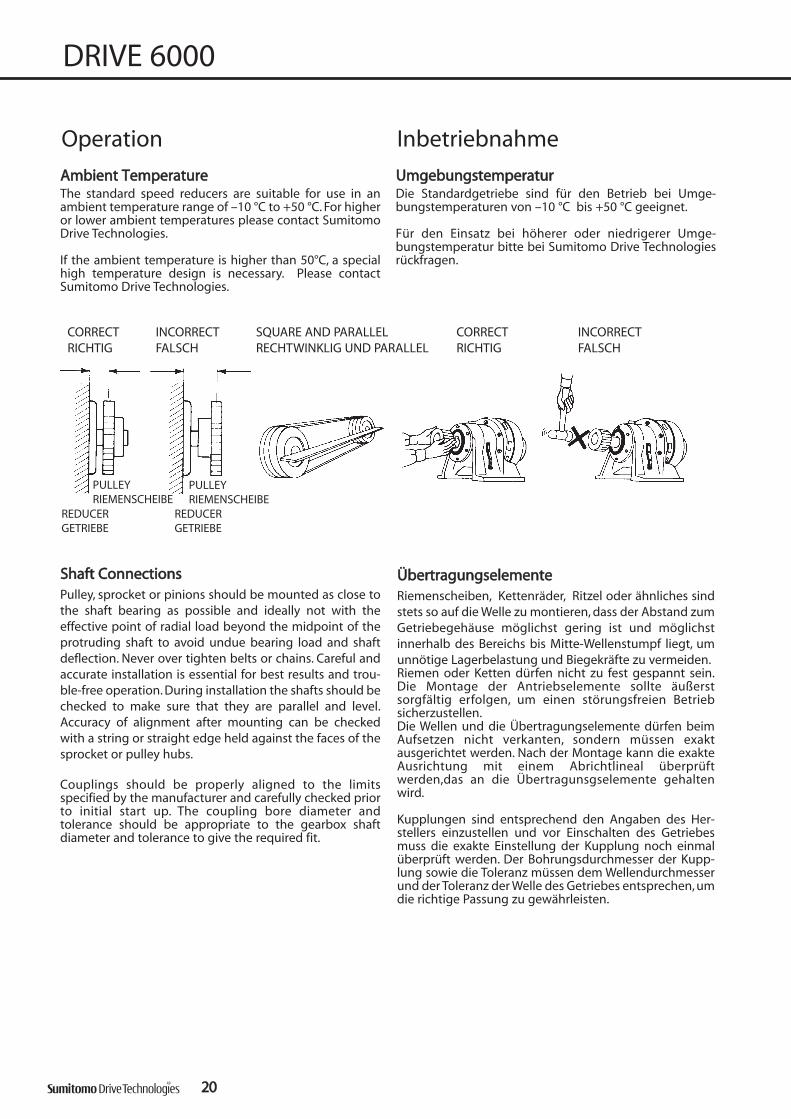
AAmmbbiieenntt TTeemmppeerraattuurreeThe standard speed reducers are suitable for use in anambient temperature range of –10 °C to +50 °C. For higheror lower ambient temperatures please contact SumitomoDrive Technologies.
If the ambient temperature is higher than 50°C, a specialhigh temperature design is necessary. Please contactSumitomo Drive Technologies.
SShhaafftt CCoonnnneeccttiioonnssPulley, sprocket or pinions should be mounted as close tothe shaft bearing as possible and ideally not with theeffective point of radial load beyond the midpoint of theprotruding shaft to avoid undue bearing load and shaftdeflection. Never over tighten belts or chains. Careful andaccurate installation is essential for best results and trou-ble-free operation. During installation the shafts should bechecked to make sure that they are parallel and level.Accuracy of alignment after mounting can be checkedwith a string or straight edge held against the faces of thesprocket or pulley hubs.
Couplings should be properly aligned to the limitsspecified by the manufacturer and carefully checked priorto initial start up. The coupling bore diameter andtolerance should be appropriate to the gearbox shaftdiameter and tolerance to give the required fit.
2200
DRIVE 6000
Operation Inbetriebnahme
UUmmggeebbuunnggsstteemmppeerraattuurrDie Standardgetriebe sind für den Betrieb bei Umge-bungstemperaturen von –10 °C bis +50 °C geeignet.
Für den Einsatz bei höherer oder niedrigerer Umge-bungstemperatur bitte bei Sumitomo Drive Technologiesrückfragen.
CORRECT INCORRECT SQUARE AND PARALLEL CORRECT INCORRECTRICHTIG FALSCH RECHTWINKLIG UND PARALLEL RICHTIG FALSCH
REDUCERGETRIEBE
REDUCERGETRIEBE
PULLEYRIEMENSCHEIBE
PULLEYRIEMENSCHEIBE
ÜÜbbeerrttrraagguunnggsseelleemmeenntteeRiemenscheiben, Kettenräder, Ritzel oder ähnliches sindstets so auf die Welle zu montieren, dass der Abstand zumGetriebegehäuse möglichst gering ist und möglichstinnerhalb des Bereichs bis Mitte-Wellenstumpf liegt, umunnötige Lagerbelastung und Biegekräfte zu vermeiden.Riemen oder Ketten dürfen nicht zu fest gespannt sein.Die Montage der Antriebselemente sollte äußerstsorgfältig erfolgen, um einen störungsfreien Betriebsicherzustellen.Die Wellen und die Übertragungselemente dürfen beimAufsetzen nicht verkanten, sondern müssen exaktausgerichtet werden. Nach der Montage kann die exakteAusrichtung mit einem Abrichtlineal überprüftwerden,das an die Übertragunsgselemente gehaltenwird.
Kupplungen sind entsprechend den Angaben des Her-stellers einzustellen und vor Einschalten des Getriebesmuss die exakte Einstellung der Kupplung noch einmalüberprüft werden. Der Bohrungsdurchmesser der Kupp-lung sowie die Toleranz müssen dem Wellendurchmesserund der Toleranz der Welle des Getriebes entsprechen, umdie richtige Passung zu gewährleisten.

DRIVE 6000
MMoouunnttiinngg CCoonnssiiddeerraattiioonnssHorizontal and vertical oil-lubricated units should bemounted in exact planes whenever possible. When theyare mounted on inclined surfaces, minor modifications arenecessary, since an inclined mounting could lower the oillevel. However, over-filling the unit with oil may causeleakage through the air vent, foaming and churning andconsequently overheating. Please contact Sumitomo DriveTechnologies.
2211
Gen
eral
Info
rmat
ion
Allg
emei
ne In
form
atio
n
CCoonnttrrooll ooff sshhaafftt llooaaddWhen power is transmitted through spur gears, belts,pulleys or chains radial forces are applied to the shafts.Theradial load capacities are calculated from load centeringand compared with the allowable radial load.
IInnssttaallllaattiioonnBe sure to install and operate CYCLO DRIVE gearmotor andspeed reducers in compliance with applicable local andnational safety codes. Appropriate guarding for rotatingshafts should always be fitted.
WWeelllleennllaasstt üübbeerrpprrüüffeennErfolgt die Kraftübertragung über Riemen, Kette oderRitzel, dann tritt an den Wellenenden eine Radial-belastung auf. Die Wellenbelastungen werden unterBerücksichtigung des Lastangriffspunktes berechnet undmit der zulässigen Belastung verglichen.
EEiinnbbaauuBeim Einbau und Betrieb von CYCLO Drive-Getriebemotoren und -Getrieben sind alle einschlägigenSicherheitsbestimmungen zu beachten. Für rotierendeWellen müssen entsprechende Sicherheitsabdeckungenvorgesehen werden.
Operation Inbetriebnahme
HHiinnwweeiissee ffüürr ddiiee AAuuffsstteelllluunnggÖlgeschmierte DRIVE für horizontale und vertikaleEinbaulage sind auf einem ebenen und starrenFundament aufzustellen. Geneigte Einbauflächen könnenunter Umständen eine Korrektur der eingefülltenSchmierstoffmengen bzw. andere Anpassungs-maßnahmen erforderlich machen. Eine Überfüllung vonölgeschmierten Getrieben kann zu Leckagen durch denAtmungsfilter, Aufschäumen des Öls und darausresultierend zu Überhitzung des Getriebes führen. InZweifelsfällen bitte Rückfrage bei Sumitomo DriveTechnologies.

11 15 21 29 35 43 59 8762056215622562356245625562656275
2222
DRIVE 6000
Lubrication Schmierung
Horizontal mounting single stage Horizontale Wellenlage einstufige Getriebe
SchmiersystemDie CYCLO Getriebeeinheiten bis Größe 6125 sowie einigemehrstufige Getriebe sind fettgeschmiert. Alle größerenGetriebeeinheiten sind normalerweise ölgeschmiert.
Lubrication SystemThe smaller CYCLO units up to size 6125 and somemultiple reduction units are grease lubricated. All largerunits are normally oil lubricated as standard.
3 5 6 8 11 13 15 17 21 25 29 35 43 51 59 71 87 119
6060 6065
6070 6075
6080 6085
6090 6095
6100 6105
6110 61156120 6125
6130 6135
6140 6145
6160 6165
6170 6175
6180 6185
6190 6195
SizeGröße
SizeGröße
single stage / einstufig
Grease (maintenance free)Fett (wartungsfrei)
Grease Fett
Grease Fett
Oil bathÖlbad
single stage / einstufig
Oil bathÖlbad

2233
DRIVE 6000
Gen
eral
Info
rmat
ion
Allg
emei
ne In
form
atio
n
Lubrication SchmierungHorizontal mounting double stage Horizontale Wellenlage zweistufige Getriebe
104 121 143 165 195 231 319 357 377 425 473 525 559 649 731 841 1003 1015 1247 1479 1894 2065 2537 3045 3481 4437 5133 6177 75696060DA6065DA6070DA6075DA6090DA6095DA6100DA6105DA6120DA6120DB6125DA6125DB
6130DB6130DC6135DB6135DC6140DC6145DC6160DB6165DB
6160DC6165DC6170DA6175DA6180DA6185DA
6170DC6175DC6180DB6185DB6190DA6195DA6190DB6195DB6205DA6205DB6215DA6215DB6225DA6225DB6235DA6235DB6245DA6245DB6255DA6255DB6265DA6275DA
Grease (maintenance free)Fett (wartungsfrei)
double stage / zweistufigSize /Größe
Oil bathÖlbad
GreaseFett

2244
DRIVE 6000Lubrication SchmierungVertical mounting single stage Vertikale Wellenlage einstufige Getriebe
104 121 143 165 195 231 319 357 377 425 473 525 559 649 731 841 1003 1015 1247 1479 1894 2065 2537 3045 3481 4437 5133 6177 75696060DA6065DA6070DA6075DA6090DA6095DA6100DA6105DA6120DA6120DB6125DA6125DB
6130DB6130DC6135DB6135DC6140DC6145DC6160DB6165DB6170DA6175DA6180DA6185DA6160DC6165DC
473
6170DC6175DC
841
6180DB6185DB
1015
6190DA6195DA6190DB6195DB
2065
6205DA6205DB
1849
6215DA6215DB
2537
6225DA6225DB6235DA6235DB6245DA6245DB6255DA6255DB6265DA
6275DA
Grease (maintenance free)Fett (wartungsfrei)
GreaseFett
Forced oil lubricationÖlumlaufschmierung
with trochoid pump/mit Trochoidenpumpe
Vertical mounting double stage Vertikale Wellenlage zweistufige Getriebe
SizeGröße
double stage / zweistufig
SizeGröße
single stage / einstufig3 5 6 8 11 13 15 17 21 25 29 35 43 51 59 71 87 119
6060606560706075608060856090609561006105611061156120612561306135614061456160616561706175618061856190619562056215622562356245625562656275
GreaseFett
GreaseFett
Grease (maintenance free)Fett (wartungsfrei)
Oil bathÖlbad
Forced oil lubricationÖlumlaufschmierung
with trochoid pump/mit Trochoidenpumpe

FFeettttsscchhmmiieerruunnggAlle fettgeschmierten Getriebe sind werksseitig mit Fettbefüllt und werden betriebsbereit geliefert.
LLeebbeennssddaauueerr--FFeettttsscchhmmiieerruunnggCYCLO Drive-Getriebemotoren und -Getriebe bis zu Größe6125 einstufig und mehrstufig sind lebensdauer-fettgeschmiert und für jede Einbaulage geeignet. DieseGetriebe werden werksseitig mit Fett ESSO Unirex N2befüllt und sind wartungsfrei für 20.000 Betriebsstundenoder 4 bis 5 Jahre.
WWeeiitteerree FFeettttsscchhmmiieerruunnggDie fettgeschmierten CYCLO Drive-Getriebemotoren und-Getriebe bis zu Größe 6125 ein- und mehrstufig, sowiegrößer als 6125 mit allen Übersetzungsverhältnissensollten nach den ersten 500 Betriebsstunden nach-geschmiert werden, spätestens jedoch nach 2 Monaten.Weitere Nachschmierungen werden alle 3 bis 6 Monateempfohlen, oder spätestens nach 2 Jahren. Diese Getriebe-einheiten sind mit Schmiernippel und Atmungsfiltern fürperiodische Nachschmierung ausgerüstet. Für Nach-füllung oder Fetterneuerung muss stets dasselbe Fett wiebei der Originalbefüllung verwendet werden. Das Mischenverschiedener Fettsorten ist nicht gestattet.
ÖÖllsscchhmmiieerruunnggAlle ölgeschmierten CYCLO Drive-Getriebemotoren und -Getriebe werden aus Sicherheitsgründen ohne Öl-befüllung geliefert.Vor Inbetriebnahme ist Erstbefüllung erforderlich.Manche Getriebe erfordern Ölbefüllung an mehrerenStellen. Hinweise zur Ölbefüllung und Ölstandskontrollefinden Sie in den Betriebsanleitungen.Wenn ölgeschmierte CYCLO Drive-Getriebe mit Fettgeschmiert werden sollen, aufgrund besondererAnforderungen bitte vorher mit Sumitomo DriveTechnologies Rücksprache nehmen.
ÖÖllwweecchhsseelliinntteerrvvaalllleeDer richtige Ölstand sollte alle 5000 Stunden überprüftwerden.Wenn das Öl verschmutzt, verbrannt oder zähflüssig ist,wechseln Sie das Öl sofort und spülen Sie, falls erfor-derlich, das Getriebe.Unter normalen Betriebsbedingungen empfehlen wireinen Ölwechsel alle 10000 Stunden. Die Intervalle solltennicht länger als 2 Jahre sein. Kürzere Ölwechselintervalle(alle 3000 bis 5000 Stunden) erhöhen die Lebensdauer.Ein Ölwechsel nach den ersten 500 Stunden ist sehrempfehlenswert. Obige Empfehlungen können unteranderen Betriebsbedingungen wie hohe Temperatur,hohe Feuchtigkeit oder korrosive Umgebung geändertwerden.Wenn eine dieser Situationen vorliegt, müssen häufigereÖlwechsel stattfinden.
2255
DRIVE 6000
Gen
eral
Info
rmat
ion
Allg
emei
ne In
form
atio
n
GGrreeaassee LLuubbrriiccaattiioonnAl grease lubricated units are filled with grease at thefactory and are ready for use.
LLiiffeettiimmee GGrreeaassee LLuubbrriiccaattiioonnCYCLO Drive gearmotor and speed reducers up to size6125 single stage and multi stage are grease lubricated forlife and suitable for any mounting position. They aresupplied filled with ESSO Unirex N2 grease and aremaintenance free for 20,000 operating hours or 4 to 5years.
OOtthheerr GGrreeaassee LLuubbrriiccaattiioonnGrease lubricated CYCLO Drive gearmotor and speedreducers up to size 6125 single- and multistage, andabove size 6125 with all ratios have to be regreased for thefirst time after 500 hours of operation, but at least after 2months. Further regreasing is recommended every 3 - 6months of operation, but at least every 2 years.These unitsare provided with grease nipples and vent plugs to allowfor periodic regreasing. Grease lubricated units have a tagwhich specifies the filled in grease. For recharge or renewalthe same kind of grease must be used. Mixing of differentgrease types is not allowed.
OOiill--LLuubbrriiccaatteedd UUnniittssAll oil-lubricated CYCLO Drive gearmotor and speedreducers are shipped without oil.They require pre-filling with oil prior to operation. Somemodels need to be supplied with oil in distinct locations.The location of the oil accessories are shown in theoperation manual. Please consult Sumitomo DriveTechnologies if oil lubricated units are used with greaselubrication, in case of special requirements.
OOiill cchhaannggee iinntteerrvvaallssOil levels must be checked every 5,000 hours. If the oil iscontaminated, burned or waxed, change the oilimmediately, and flush the gear if necessary. Under normaloperating conditions oil should be changed every 10,000hours or after 2 years at the latest. A more regular oilchange (every 3000 or 5000 hours) will increase the gearlifetime.We recommend changing the oil after the first 500 hoursof operation.The recommendations above do not apply to abnormaloperating conditions, i.e., high temperature, high humidityor corrosive environments. If any of these situations exist,the lubricant may have to be changed more frequently.
Lubrication Schmierung

2266
DRIVE 6000
Selection of oil viscosity by ambient/operating temperature
Lubrication Schmierung
Ölviskositätsklassen nach Betriebstemperatur/Umgebungstemperatur
CLP 68CLP 100CLP 150CLP 220CLP 320
-20°C 0° +20° +40° +60° +80° +100°
Lubricants as per DIN 51517 part 3
Schmierstoff nachDIN 51517 Teil 3
possible working temperatures °Cmögliche Betriebstemperatur °C
ambient temperature °CUmgebungstemperatur °C
LubricantsGrease types
SchmierstoffeFettsorten
H V W H V W H V W
6060 6065
6070 6075
6080 6085
6090 6095
6100 6105
6110 6115
6120 6125
6130 6135
6140 6145
6160 6165
6170 6175
6180 6185
6190 6195
6205
6215
6225
6235
6245
6255
6265
6275
ESSO
Unirex N2
ESSO
Unirex N2
ESSO
Unirex N2
oder/or
Öl/Oil
ESSO
Unirex N2
oder/or
Öl/Oil
Öl
Oil
nicht lieferbar
not available
Öl
Oil
ESSO
Unirex N2
SHELL
Alvania EP2
SHELL Alvania EPFL 0ESSO Unirex N2
(maintenance free/wartungsfrei)
Öl
OilSHELL Alvania EPFL 0
ESSO
Unirex N2
SHELL
Alvania EP2
SHELL
Alvania EP2
oder/or
Öl/Oil
Übersetzung 104 und größer
Ratio 104 and aboveRatio 6 to 119Ratio 3 & 5
Übersetzung 3 & 5 Übersetzung 6 bis 119
Manufacturer type of oil Manufacturer type of oil Manufacturer type of oilHersteller Öl Hersteller Öl Hersteller Öl
ARAL Degol BG DEA Falcon CLP MOBIL MobilgearAVIA Gear RSX ELF Reductelf SP OPTIMOL Ultra
BP Energol GR-XP ESSO Spartan EP SHELL OmalaCASTROL AlphaMW KLÜBER Klüberoil GEM1 TOTAL Carter EP
Any oil type that meets the requirements as per DIN 51517 part 3 may be used. Make sure that the correctviscosity class as per 51519 is selected depending onactual operating temperature.
Synthetic oil types on Polyglycol-basis can be used also.The compatibility with the seal material must be checked.Please contact Sumitomo Drive Technologies in suchcases.
Geeignet sind alle Schmieröle, die die Anforderungennach DIN 51517 Teil 3 erfüllen.Je nach Umgebungs- oder Betriebstemperatur muss dierichtige Viskositätsklasse nach DIN 51519 gewähltwerden.Synthetische Schmierstoffe auf Polyglykolbasis könnenauch verwendet werden. Kompatibilität mit Dichtungs-material muss jedoch geprüft werden. Für solche Fällebitte Rückfrage bei Sumitomo Drive Technologies.
Recommended Oil Types Empfohlene Schmieröle

2277
DRIVE 6000
Gen
eral
Info
rmat
ion
Allg
emei
ne In
form
atio
n
Lubrication Schmierung
Grease quantity Fettmenge
66113300DDAA 66113300DDBB 66113300DDCC 66114400DDAA 66114400DDBB 66114400DDCC 66116600DDAA 66116600DDBB 66117700DDAA 66117700DDBB
66113355DDAA 66113355DDBB 66113355DDCC 66114455DDAA 66114455DDBB 66114455DDCC 66116655DDAA 66116655DDBB 66117755DDAA 66117755DDBB
1st stage 1. Stufe2nd stage 2. Stufe
66118800DDBB 66119900DDAA 66119900DDBB
66118855DDBB 66119955DDAA 66119955DDBB
1st stage 1. Stufe2nd stage 2. Stufe
1st stage 1. Stufe2nd stage 2. Stufe
25 90 140 25 90 140 90 140 90 140
450 450 450 450 450 450 750 750 1000 1000
SS iizzee//GGrröößßee
Output/Abtrieb 300 300 300 300 300 300 300 300 500 500
SS iizzee//GGrröößßee
450 150
1100 1500
600 700Output/Abtrieb
66223355DDBB
66220055DDBB66220055DDAA 66223355DDAA66221155DDAA 66221155DDBB 66222255DDAA 66222255DDBB
450 150 450 450 750 450 1000 750
1500 1500 1500 2000 2000 2500 2500 4000
1000700 700 700 800 800 900 900
66226655DDAA
1100 750 1100 1000 1500 1500
66224455DDAA 66224455DDBB 66225555DDAA 66225555DDBB
4000 4500 4500 6000
SS iizzee//GGrröößßee
Output/Abtrieb
6000 8000
1000 1100 1100 1200 1200 1300
Approximate oil quantities [l] Ungefähre Ölmengen [l]
The table shows the approximate quantities. The actualquantity should be determined by means of the oil levelgauge (please refer to Operating Manual).
Die angegebenen Mengen sind durchschnittlicheRichtwerte. Die genaue Menge ist anhand des vorge-schriebenen Ölstandes zu kontrollieren (sieheBetriebsanleitung).
6130 6140 6160 6170 6180 61906135 6145 6165 6175 6185 6195
[l] 0,7 0,7 1,4 1,9 2,5 4,0 5,5 8,5 10 15 16 21 29 566160DC 6170DC 6180DB 6190DA 6190DB6165DC 6175DC 6185DB 6195DA 6195DB
[l] 1,5 2,4 3,5 5,8 6,0 6,0 6,0 10 10 11 11 17 17 186245DB 6255DA 6255DB 6265DA 6275DA
18 23 23 32 70
6130 6140 6160 6170 6180 61906135 6145 6165 6175 6185 6195
[l] 1,1 1,1 1,0 1,9 2,0 2,7 5,7 7,5 10 12 15 42 51 606160DC 6170DC 6180DB 6190DA 6190DB6165DC 6175DC 6185DB 6195DA 6195DB
[l] 1,0 1,9 2,0 2,7 2,7 11 11 14 14 18 18 23 23 296245DB 6255DA 6255DB 6265DA 6275DA
29 42 42 51 60
6130 6140 6160 6170 6180 61906135 6145 6165 6175 6185 6195
[l] 0,25 0,25 0,9 1,5 1,3 2 3 4 5 7,5 8 11 14 306160DC 6170DC 6180DB 6190DA 6190DB6165DC 6175DC 6185DB 6195DA 6195DB
[l] 1,0 2,0 2,3 3,8 4,0 4,0 4,0 5,5 5,5 6,0 6,0 9,5 9,5 106245DB 6255DA 6255DB 6265DA 6275DA
10 13 13 17 44
CCHHHH ……,, CCHHHHXX ……,, CCHHVV ……,, CCHHVVXX ……
DimensionGröße
6205 6215 6225 6235 6245 6255 6265 6275
DimensionGröße
6205DA 6205DB 6215DA 6215DB 6225DA 6225DB 6235DA 6235DB 6245DA
DimensionGröße
CCVVVV ……,, CCVVVVXX ……
DimensionGröße
6205 6215 6225 6235 6245 6255 6265 6275
DimensionGröße
6205DA 6205DB 6215DA 6215DB 6225DA 6225DB 6235DA 6235DB
6215 6225 6235 6245
DimensionGröße
CCHHFF ……,, CCHHFFXX ……
DimensionGröße
6205
6235DA
6245DA
6255
6235DB 6245DA
DimensionGröße
6265 6275
DimensionGröße
6205DA 6205DB 6215DA 6215DB 6225DA 6225DB
Fettmenge [g] für LebensdauerfettschmierungGrease quantity [g] for lifetime grease lubrication
60606065
25
-
35
60706075
25
-
35
60806085
65
-
70
60906095
90
-
100
61006105
140
-
100
61106115
200
-
90
61206125
330
-
120
6060DA6065DA
25
25
35
6070DA6075DA
25
25
35
6090DA6095DA
25
90
100
6100DA6105DA
25
140
100
6120DA6125DA
25
330
120
6120DB6125DB
90
330
120
SizeGröße
1st stage1. Stufe
2nd stage2. StufeOutputAbtrieb

2288
DRIVE 6000

2299
DRIVE 6000
GGeeaarrmmoottoorrss SSeelleeccttiioonn TTaabblleess GGeettrriieebbeemmoottoorr--AAuusswwaahhlllliisstteenn
Gea
rmot
or S
elec
tion
Get
rieb
emot
or-A
usw
ahl

Rating tables are based on a service factor fB1 of 1.0, i.e. 10 hoursper day at uniform load.The service factors apply to all motor power with a speed of n1 = 1400 min-1. The actual speed can (depending on theoperating conditions) deviate from the theoretical value given inthe table on page 246.
i = reduction ration2 = output speed [min-1]M2mot = output torque [Nm] with
reference to the driving motorfB = service factorFR 2 = allowable radial load applied to
mid of shaft end [N]
Alle Angaben in den Auswahllisten gelten für einenBetriebsfaktor fB1von 1,0, d.h für 10 Stunden pro Tag beigleichförmiger Belastung.Die Betriebsfaktoren gelten bei allen Motorleistungen für n1 = 1400 min-1. Die tatsächliche Drehzahl kann (abhängig vonden Betriebsbedingungen) von dem in Tabelle Seite 246genannten theoretischen Wert abweichen.i = Übersetzungn2 = Antriebsdrehzahl [min-1]M2mot = Abtriebsdrehmoment [Nm] auf
Antriebsmotor bezogenfB = BetriebsfaktorFR 2 = zulässige Radialkraft auf Mitte
Wellenende [N]
EExxaammppllee // BBeeiissppiieell:: CCNNHHMM001122--66112255EE--552255//GGFF6633SS//44
Gearmotors Selection Table 00,,1122 kkWW Getriebemotor-Auswahllisten
1,01 6120DA 100 110 1201,21 6125DA 100 110 1201,50 6130DB 102 112 1221,81 6135DB 102 112 122
1,14 6120DA 100 110 1201,36 6125DA 100 110 1201,98 14700 6130DB 102 112 122
1,24 6120DA 100 110 1201,49 6125DA 100 110 1201,84 14700 6130DB 102 112 122
1,32 6120DA 100 110 1201,58 6125DA 100 110 1201,96 14700 6130DB 102 112 122
0,80 1460 6105DA 100 110 1201,41 6120DA 100 110 1201,69 6125DA 100 110 1202,09 14700 6130DB 102 112 122
0,89 4140 6105DA 100 110 1201,56 6120DA 100 110 1201,87 6125DA 100 110 120
0,83 6100DA 100 110 1200,99 6105DA 100 110 1201,74 6120DA 100 110 1202,08 6125DA 100 110 120
0,93 6100DA 100 110 1201,12 6105DA 100 110 1201,94 9810 6120DA 100 110 120
0,98 6100DA 100 110 1201,18 6105DA 100 110 1202,06 9810 6120DA 100 110 120
CNHMCHHM
CNFMCHFM
525
473
731
649
595
Größe
FR2
[N]
357
425
377
5400
9810
5400
5400
n2
[min-1]
M2Mot
[Nm]
3,92 263
9810
14700
9810
9810
9810
9810
9810348
3,29 313
3,71 278
2,96
5381,92
2,16 478
2,35 438
4122,50
Dimension pageMaßblatt Seite
2,67 387
CNVMCHVM
559
fB
Ratio
Über-setzung
Size
0,88 3140 6095DA 100 110 1201,10 6100DA 100 110 1201,32 6105DA 100 110 1202,29 9810 6120DA 100 110 120
1,03 3340 6095DA 100 110 1201,29 6100DA 100 110 1201,54 6105DA 100 110 1202,69 9810 6120DA 100 110 120
0,91 6090DA 100 110 1201,22 6095DA 100 110 1201,52 6100DA 100 110 1201,83 6105DA 100 110 120
1,08 6090DA 100 110 1201,44 6095DA 100 110 1201,80 5400 6100DA 100 110 120
1,28 6090DA 100 110 1201,70 6095DA 100 110 1202,13 5400 6100DA 100 110 120
1,47 6090DA 100 110 1201,80 6095DA 100 110 120
1,74 6090DA 100 110 1201,86 6095DA 100 110 120
1,04 6090 70 78 861,21 6095 70 78 86
0,81 1770 6075DA 100 110 1202,03 3340 6090DA 100 110 120
1,01 2560 6085 70 78 861,76 3340 6090 70 78 86
5400
5,13 201 2735400
FR2 Size
[N] GrößeCNFMCHFM
Über-setzung
7,18 1443340
195
6,06 170 2313340
54004,39 235 319
8,48 1223340
165
143
12111,6 89,1
3340
3340
9,79 105
119
104
87
11,8
13,5
16,1
92,5
76,6
67,6
3340
RatioDimension page
Maßblatt Seiten2 M2Mot
fB
[min-1] [Nm]CNVMCHVM
CNHMCHHM
3300
DRIVE 6000

EExxaammppllee // BBeeiissppiieell:: CCNNHHMM001122--66007755EE--4433//GGFF6633SS//44
3311
DRIVE 6000
Gearmotors Selection Table 00,,1122 kkWW Getriebemotor-Auswahllisten
Gea
rmot
or S
elec
tion
Get
rieb
emot
or-A
usw
ahl
Rating tables are based on a service factor fB1 of 1.0, i.e. 10 hoursper day at uniform load.The service factors apply to all motor power with a speed of n1 = 1400 min-1. The actual speed can (depending on theoperating conditions) deviate from the theoretical value given inthe table on page 246.
i = reduction ratio
n2 = output speed [min-1]
M2mot = output torque [Nm] with reference to the driving motor
fB = service factor
FR 2 = allowable radial load applied to mid of shaft end [N]
Alle Angaben in den Auswahllisten gelten für einenBetriebsfaktor fB1von 1,0, d.h für 10 Stunden pro Tag beigleichförmiger Belastung.Die Betriebsfaktoren gelten bei allen Motorleistungen für n1 = 1400 min-1. Die tatsächliche Drehzahl kann (abhängig vonden Betriebsbedingungen) von dem in Tabelle Seite 246genannten theoretischen Wert abweichen.
i = Übersetzung
n2 = Antriebsdrehzahl [min-1]
M2mot = Abtriebsdrehmoment [Nm] auf Antriebsmotor bezogen
fB = Betriebsfaktor
FR 2 = zulässige Radialkraft auf Mitte Wellenende [N]
1,00 6080 70 78 861,38 6085 70 78 862,10 3340 6090 70 78 86
0,83 6070 70 78 861,13 6075 70 78 861,54 2560 6080 70 78 861,95 2560 6085 70 78 86
0,83 6070 70 78 861,19 6075 70 78 861,60 6080 70 78 862,01 6085 70 78 86
0,93 1180 6065 70 78 861,39 6070 70 78 861,86 6075 70 78 86
0,92 6060 70 78 861,14 6065 70 78 861,71 6070 70 78 862,27 6075 70 78 86
0,92 6060 70 78 861,38 6065 70 78 861,88 1770 6070 70 78 86
43
55,219,7
CNHM
23,7
39,727,5
45,9
CNFM
71
n2
[min-1]
M2Mot
[Nm]
2560
Größe
fB
Ratio
1180
1180
[N] CNVMÜber-
setzung
163059
256051
1660
SizeFR2
Dimension pageMaßblatt Seite
35
29
32,6 33,41770
40 27,21770
48,3 22,5
0,92 6060 70 78 861,38 6065 70 78 861,92 1770 6070 70 78 86
1,53 6060 70 78 861,90 6065 70 78 86
1,67 6060 70 78 862,35 6065 70 78 86
1,67 6060 70 78 862,38 6065 70 78 86
1,67 6060 70 78 862,38 6065 70 78 86
1,67 6060 70 78 862,38 6065 70 78 86
1,67 6060 70 78 862,38 6065 70 78 86
1,67 6060 70 78 862,38 6065 70 78 86
127 8,6
233
175
4,67
6,22
93,3 11,7
108 10,1
21
17
15
13
56
CNVM
1180
1180
118016,366,7
82,4 13,2
19,4
Dimension pageMaßblatt Seite
Ratio
Über-setzung
Size
Größe
FR2
[N]
fB
n2
[min-1]
M2Mot
[Nm] CNHM CNFM
251180
1180
111120
821 8
717 6

Rating tables are based on a service factor fB1 of 1.0, i.e. 10 hoursper day at uniform load.The service factors apply to all motor power with a speed of n1 = 1400 min-1. The actual speed can (depending on theoperating conditions) deviate from the theoretical value given inthe table on page 246.
i = reduction ration2 = output speed [min-1]M2mot = output torque [Nm] with
reference to the driving motorfB = service factorFR 2 = allowable radial load applied to
mid of shaft end [N]
3322
DRIVE 6000
Gearmotors Selection Table 00,,1188 kkWW Getriebemotor-AuswahllistenAlle Angaben in den Auswahllisten gelten für einenBetriebsfaktor fB1von 1,0, d.h für 10 Stunden pro Tag beigleichförmiger Belastung.Die Betriebsfaktoren gelten bei allen Motorleistungen für n1 = 1400 min-1. Die tatsächliche Drehzahl kann (abhängig vonden Betriebsbedingungen) von dem in Tabelle Seite 246genannten theoretischen Wert abweichen.
i = Übersetzungn2 = Antriebsdrehzahl [min-1]M2mot = Abtriebsdrehmoment [Nm] auf
Antriebsmotor bezogenfB = BetriebsfaktorFR 2 = zulässige Radialkraft auf Mitte
Wellenende [N]
EExxaammppllee // BBeeiissppiieell:: CCHHHHMM001188--66113355DDBB--447733//GGFF6633MM//44
0,81 9810 6125DA 100 110 1201,00 6130DB 102 112 1221,21 6135DB 102 112 1221,57 6140DC 102 112 1221,76 6145DC 102 112 122
0,91 9810 6125DA 100 110 1201,32 6130DB 102 112 1221,52 6135DB 102 112 1221,77 16000 6140DC 102 112 122
0,83 6120DA 100 110 1200,99 6125DA 100 110 1201,23 6130DB 102 112 1221,48 6135DB 102 112 1221,93 16000 6140DC 102 112 122
0,88 6120DA 100 110 1201,06 6125DA 100 110 1201,31 6130DB 102 112 1221,58 6135DB 102 112 1222,05 16000 6140DC 102 112 122
0,94 6120DA 100 110 1201,12 6125DA 100 110 1201,39 6130DB 102 112 1221,61 6135DB 102 112 1222,19 16000 6140DC 102 112 122
1,04 6120DA 100 110 1201,25 6125DA 100 110 1201,55 6130DB 102 112 1221,86 6135DB 102 112 122
1,16 6120DA 100 110 1201,39 6125DA 100 110 1201,72 6130DB 102 112 1221,98 6135DB 102 112 122
1,29 6120DA 100 110 1201,57 6125DA 100 110 1201,94 14700 6130DB 102 112 122
1,37 6120DA 102 112 1221,65 6125DA 102 112 1222,05 14700 6130DB 102 112 122
425
377
357
595
559
525
473
9810
14700
9810
9810
9810
14700
9810
14700
FR2 Size
[N] GrößeCNFMCHFM
Über-setzung
2,39 648
1,94
2,19
796
707
731
649
2,54 609
14700
16000
14700
9810
14700
9810
14700
3,98
411
389
572
515
463
2,70
3,00
3,34
3,77
RatioDimension page
Maßblatt Seiten2 M2Mot
fB
[min-1] [Nm]CNVMCHVM
CNHMCHHM
0,88 4520 6105DA 100 110 1201,53 6120DA 100 110 1201,85 6125DA 100 110 120
0,86 6100DA 100 110 1201,03 6105DA 100 110 1201,79 9810 6120DA 100 110 120
0,81 3240 6095DA 100 110 1201,01 6100DA 100 110 1201,22 6105DA 100 110 1202,12 9810 6120DA 100 110 120
0,96 3340 6095DA 100 110 1201,20 6100DA 100 110 1201,44 6105DA 100 110 1202,39 9810 6120DA 100 110 120
0,85 6090DA 100 110 1201,14 6095DA 100 110 1201,42 6100DA 100 110 1201,70 6105DA 100 110 1202,39 9810 6120DA 100 110 120
0,98 6090DA 100 110 1201,20 6095DA 100 110 1201,64 6100DA 100 110 1201,97 6105DA 100 110 120
1,16 6090DA 100 110 1201,24 6095DA 100 110 1201,94 5400 6100DA 100 110 120
0,81 3340 6095 70 78 861,17 6100 70 78 861,59 6105 70 78 86
1,35 6090DA 100 110 1201,63 6095DA 100 110 1202,25 5400 6100DA 100 110 120
1,17 6090 70 78 861,46 6095 70 78 862,41 4810 6100 70 78 86
6,15
7,28
8,61
Dimension pageMaßblatt Seite
3484,45
5,2 297
CNVM
fB
Ratio
Über-setzung
Size
CNHM CNFMGröße
FR2n2
[min-1]
M2Mot
[Nm] [N]
13,7
16,3
9,93
11,7
11,9
156
180
252
143
3340
3340
3340
121
119
104
87
212
100
113
137
132
5400
5400
3340
319
273
231
195
165
9810
5400
5400
3340
5400
4740

3333
DRIVE 6000
Gearmotors Selection Table 00,,1188 kkWW Getriebemotor-Auswahllisten
Gea
rmot
or S
elec
tion
Get
rieb
emot
or-A
usw
ahl
Rating tables are based on a service factor fB1 of 1.0, i.e. 10 hoursper day at uniform load.The service factors apply to all motor power with a speed of n1 = 1400 min-1. The actual speed can (depending on theoperating conditions) deviate from the theoretical value given inthe table on page 246.
i = reduction ratio
n2 = output speed [min-1]
M2mot = output torque [Nm] with reference to the driving motor
fB = service factor
FR 2 = allowable radial load applied to mid of shaft end [N]
Alle Angaben in den Auswahllisten gelten für einenBetriebsfaktor fB1von 1,0, d.h für 10 Stunden pro Tag beigleichförmiger Belastung.Die Betriebsfaktoren gelten bei allen Motorleistungen für n1 = 1400 min-1. Die tatsächliche Drehzahl kann (abhängig vonden Betriebsbedingungen) von dem in Tabelle Seite 246genannten theoretischen Wert abweichen.
i = Übersetzung
n2 = Antriebsdrehzahl [min-1]
M2mot = Abtriebsdrehmoment [Nm] auf Antriebsmotor bezogen
fB = Betriebsfaktor
FR 2 = zulässige Radialkraft auf Mitte Wellenende [N]
EExxaammppllee // BBeeiissppiieell:: CCNNHHMM001188--66007755EE--4433//GGFF6633MM//44
0,92 2560 6085 70 78 861,40 6090 70 78 861,54 6095 70 78 862,42 4790 6100 70 78 86
1,03 6080 70 78 861,30 6085 70 78 861,72 6090 70 78 861,87 6095 70 78 86
1,07 6080 70 78 861,34 6085 70 78 861,84 3340 6090 70 78 86
0,93 6070 70 78 861,24 6075 70 78 861,39 6080 70 78 861,63 6085 70 78 862,42 3340 6090 70 78 86
1,14 6070 70 78 861,51 6075 70 78 861,61 6080 70 78 861,82 6085 70 78 86
0,92 1180 6065 70 78 861,26 6070 70 78 861,59 6075 70 78 861,89 2520 6080 70 78 86
0,92 1180 6065 70 78 861,28 6070 70 78 861,63 6075 70 78 861,89 2460 6080 70 78 86
29
1770
49 33,3
40,6 40,2
25
2560
3340
1770
1770
51
43
352560
1740
27,8 58,6
FR2
20
24,1
81,6
67,8
2560
Size
[N] Größe
RatioDimension page
Maßblatt Seiten2 M2Mot
fB
[min-1] [Nm] CNFMÜber-
setzungCNVMCNHM
56,8 28,7
71
59
33 49,4
3340
2560
1 6060 70 78 861,3 6065 70 78 861,9 1770 6070 70 78 86
1,1 6060 70 78 861,6 6065 70 78 861,9 1770 6070 70 78 86
1,1 6060 70 78 861,6 6065 70 78 861,9 1690 6070 70 78 86
1,1 6060 70 78 861,6 6065 70 78 861,9 1680 6070 70 78 86
1,1 6060 70 78 861,6 6065 70 78 861,9 1590 6070 70 78 86
1,1 6060 70 78 861,6 6065 70 78 861,9 1420 6070 70 78 86
1,1 6060 70 78 861,6 6065 70 78 861,9 1280 6070 70 78 86
284 5,6 15 4740 6100 5 70 78 86
473 3,36 15 4740 6100 3 70 78 86
83,5 19,5
12,6
24,1
14,9
94,7
109
67,6
9,2
6,9
1180
1110
817
714
CNVMCNHM
17
6
21
RatioDimension page
Maßblatt Seiten2 M2Mot
fB
[min-1] [Nm] CNFMÜber-
setzung
1180
FR2 Size
[N] Größe
178
237
15
13
11
8
129
17,21180
1180

3344
DRIVE 6000
Gearmotors Selection Table 00,,2255 kkWW Getriebemotor-AuswahllistenRating tables are based on a service factor fB1 of 1.0, i.e. 10 hoursper day at uniform load.The service factors apply to all motor power with a speed of n1 = 1400 min-1. The actual speed can (depending on theoperating conditions) deviate from the theoretical value given inthe table on page 246.
i = reduction ration2 = output speed [min-1]M2mot = output torque [Nm] with
reference to the driving motorfB = service factorFR 2 = allowable radial load applied to
mid of shaft end [N]
Alle Angaben in den Auswahllisten gelten für einenBetriebsfaktor fB1von 1,0, d.h für 10 Stunden pro Tag beigleichförmiger Belastung.Die Betriebsfaktoren gelten bei allen Motorleistungen für n1 = 1400 min-1. Die tatsächliche Drehzahl kann (abhängig vonden Betriebsbedingungen) von dem in Tabelle Seite 246genannten theoretischen Wert abweichen.
i = Übersetzungn2 = Antriebsdrehzahl [min-1]M2mot = Abtriebsdrehmoment [Nm] auf
Antriebsmotor bezogenfB = BetriebsfaktorFR 2 = zulässige Radialkraft auf Mitte
Wellenende [N]
EExxaammppllee // BBeeiissppiieell:: CCHHHHMM0033--66114455DDCCEE--552255//GGFF6633MM//44
0,87 14700 6135DB 102 112 1221,13 6140DC 102 112 1221,26 6145DC 102 112 122
0,95 6130DB 102 112 1221,09 6135DB 102 112 1221,27 6140DC 102 112 1221,42 6145DC 102 112 122
0,88 6130DB 102 112 1221,07 6135DB 102 112 1221,39 6140DC 102 112 1221,55 6145DC 102 112 122
0,94 6130DB 102 112 1221,13 6135DB 102 112 1221,48 6140DC 102 112 1221,65 6145DC 102 112 122
0,81 9810 6125DA 100 100 1201,00 6130DB 102 112 1221,16 6135DB 102 112 1221,57 6140DC 102 112 1221,76 6145DC 102 112 122
0,90 9810 6125DA 100 100 1201,11 6130DB 102 112 1221,34 6135DB 102 112 1221,75 16000 6140DC 102 112 122
0,83 6120DA 100 100 1201,00 6125DA 100 100 1201,24 6130DB 102 112 1221,43 6135DB 102 112 1221,95 16000 6140DC 102 112 1220,93 6120DA 100 100 1201,13 6125DA 100 100 1201,40 6130DB 102 112 1221,68 6135DB 102 112 1222,19 16000 6140DC 102 112 122
0,99 6120DA 100 100 1201,19 6125DA 100 100 1201,47 6130DB 102 112 1221,78 6135DB 102 112 122
425
595
473
1,89 1140
736
14700
16000
14700
2,32 926
FR2
2,13 1010
16000
14700
GrößeCNFMCHFM
Über-setzung
16000
16000
RatioDimension page
Maßblatt Seiten2 M2Mot
fB
[min-1] [Nm]
Size
[N]CNVMCHVM
CNHMCHHM
559
525
731
649
377
357
2,47
2,63
870
817
14700
16000
14700
2,92
9810
14700
9810
14700
3,66 587
3,87 556
9810
147003,25 662
1,10 6120DA 100 110 1201,33 6125DA 100 110 1201,65 6130DB 102 112 1221,99 6135DB 102 112 122
1,29 6120DA 100 110 1201,56 6125DA 100 110 1201,93 14700 6130DB 102 112 122
0,88 4940 6105DA 100 110 1201,52 6120DA 100 110 1201,72 6125DA 100 110 1201,84 9810 6125DB 100 110 120
0,87 6100DA 100 110 1201,04 6105DA 100 110 1201,72 6120DA 100 110 1201,82 6120DB 100 110 120
0,82 3340 6095DA 100 110 1201,02 6100DA 100 110 1201,23 6105DA 100 110 1201,72 6120DA 100 110 1202,15 6120DB 100 110 120
0,87 3340 6095DA 100 110 1201,18 6100DA 100 110 1201,42 6105DA 100 110 1201,72 6120DA 100 110 1202,48 6120DB 100 110 120
0,84 6090DA 100 110 1200,89 6095DA 100 110 1201,39 6100DA 100 110 1201,72 6105DA 100 110 1202,93 9810 6120DB 100 110 1200,84 6100 70 78 861,14 6105 70 78 86
0,97 6090DA 100 110 1201,17 6095DA 100 110 1201,62 6100DA 100 110 1201,72 6105DA 100 110 1203,41 9810 6120DB 100 110 120
11,6
223
13,35400
3340
5400
196 4710
162
4,33
5,05
497
CNVMCHVM
CNHMCHHM
n2 M2Mot
fB
[min-1] [Nm]
Size
[N] GrößeCNFMCHFM
Über-setzung
FR2 RatioDimension page
Maßblatt Seite
425
9,65
11,4 188
5,97 360
7,08 304
8,36 257
104
3340
9810
121
231
143
14700
9810
9810
5400
5400
9810
319
119
9810
9810
273
5400
195
165

3355
DRIVE 6000
Gearmotors Selection Table 00,,2255 kkWW Getriebemotor-AuswahllistenRating tables are based on a service factor fB1 of 1.0, i.e. 10 hoursper day at uniform load.The service factors apply to all motor power with a speed of n1 = 1400 min-1. The actual speed can (depending on theoperating conditions) deviate from the theoretical value given inthe table on page 246.
i = reduction ration2 = output speed [min-1]M2mot = output torque [Nm] with
reference to the driving motorfB = service factorFR 2 = allowable radial load applied to
mid of shaft end [N]
Alle Angaben in den Auswahllisten gelten für einenBetriebsfaktor fB1von 1,0, d.h für 10 Stunden pro Tag beigleichförmiger Belastung.Die Betriebsfaktoren gelten bei allen Motorleistungen für n1 = 1400 min-1. Die tatsächliche Drehzahl kann (abhängig vonden Betriebsbedingungen) von dem in Tabelle Seite 246genannten theoretischen Wert abweichen.
i = Übersetzungn2 = Antriebsdrehzahl [min-1]M2mot = Abtriebsdrehmoment [Nm] auf
Antriebsmotor bezogenfB = BetriebsfaktorFR 2 = zulässige Radialkraft auf Mitte
Wellenende [N]
EExxaammppllee //BBeeiissppiieell:: CCNNHHMM0033--66008855EE--5599//GGFF6633MM//44
0,80 6060 70 78 861,13 6065 70 78 861,39 6070 70 78 861,63 6075 70 78 862,37 2450 6080 70 78 86
0,80 6060 70 78 861,14 6065 70 78 861,39 6070 70 78 861,63 6075 70 78 862,37 2330 6080 70 78 86
0,80 6060 70 78 861,14 6065 70 78 861,39 6070 70 78 861,63 6075 70 78 862,37 2260 6080 70 78 860,80 6060 70 78 861,14 6065 70 78 861,39 6070 70 78 861,63 6075 70 78 862,37 2100 6080 70 78 860,80 6060 70 78 861,14 6065 70 78 861,39 6070 70 78 861,63 6075 70 78 862,37 1900 6080 70 78 860,80 6060 70 78 861,14 6065 70 78 861,39 6070 70 78 861,63 6075 70 78 862,37 1750 6080 70 78 86
276 8,00 11,0 4740 6100 5 70 78 86460 4,8 11,0 4740 6100 3 70 78 86
230 9,97
710
61280
173 13,1
811
81410
1321,4
125 18,1
1090
111580
1170
1061670
FR2
15
1180
1670
1770
Ratio
1180
Dimension pageMaßblatt Seite
n2 M2Mot
fB
[min-1] [Nm]
Size
[N] CNVMCNHM
17
Größe CNFMÜber-
setzung
81,2
92
27,9
24,7
0,84 6090 70 78 861,05 6095 70 78 861,73 6100 70 78 862,01 6105 70 78 86
1,01 6090 70 78 861,11 6095 70 78 861,74 6100 70 78 862,02 6105 70 78 86
0,94 2560 6085 70 78 861,24 6090 70 78 861,34 6095 70 78 862,06 5010 6100 70 78 860,96 2560 6085 70 78 861,33 6090 70 78 861,63 6095 70 78 862,24 5080 6100 70 78 86
0,89 1620 6075 70 78 861,00 6080 70 78 861,18 6085 70 78 861,74 6090 70 78 862,41 6095 70 78 86
0,82 6070 70 78 861,09 6075 70 78 861,16 6080 70 78 861,31 6085 70 78 860,90 6070 70 78 861,14 6075 70 78 861,36 6080 70 78 861,87 6085 70 78 86
0,92 6070 70 78 861,18 6075 70 78 861,36 6080 70 78 861,90 6085 70 78 86
0,91 1180 6065 70 78 861,28 6070 70 78 861,63 6075 70 78 861,91 2380 6080 70 78 86
59
51
29
251740
2450
1770 21
3340
2560
1730
2500
39,4
47,6 47,7
55,2 41,1
57,5
23,4
15,9
19,4
143
86
117
27,1
32,1
83,8
81,7
65,7 34,5
1730
CNVMCNHM
87
Größe CNFMÜber-
setzung
3340
Dimension pageMaßblatt Seite
n2 M2Mot
fB
[min-1] [Nm]
Size
[N]
FR2 Ratio
3340
4790
35
71
43
3340
4770
2560
3340
Gea
rmot
or S
elec
tion
Get
rieb
emot
or-A
usw
ahl

0,94 6130DB 102 112 1221,14 6135DB 102 112 1221,48 6140DC 102 112 1221,66 6145DC 102 112 1222,12 22100 6160DC 104 114 124
0,80 9810 6125DA 100 110 1201,00 6130DB 102 112 1221,20 6135DB 102 112 1221,56 6140DC 102 112 1221,71 6145DC 102 112 1222,24 22100 6160DC 104 114 124
0,90 9810 6125DA 100 110 1201,11 6130DB 102 112 1221,34 6135DB 102 112 1221,75 16000 6140DC 102 112 122
0,87 6120DA 100 110 1201,05 6125DA 100 110 1201,30 6130DB 102 112 1221,57 6135DB 102 112 1222,05 16000 6140DC 102 112 122
1,03 6120DA 100 110 1201,16 6125DA 100 110 1201,24 6125DB 100 110 1201,54 6130DB 102 112 1221,86 6135DB 102 112 122
1,16 6120DA 100 110 1201,23 6120DB 100 110 1201,47 6125DB 100 110 1201,82 14700 6130DB 102 112 122
0,83 3610 6105DA 100 110 1201,16 6120DA 100 110 1201,45 6120DB 100 110 1201,74 6125DB 100 110 1202,16 14700 6130DB 102 112 122
165
3,94 808
722
14700
16000
14700
9810
195
14700
9810
377
9810
5,15 618
7,21 441
8,52 373
273
fB
[min-1] [Nm]
6,08 523
3,73 853
4,40
n2 M2Mot
CNVMCHVM
CNHMCHHM
319
RatioDimension page
Maßblatt Seite
CNFMCHFM
Über-setzung
357
231
Size
[N] Größe
FR2
14700
16000
14700
9810
EExxaammppllee // BBeeiissppiieell:: CCHHHHMM0044--66116655DDCC--773311//TTFF7711MM//44
3366
DRIVE 6000
Gearmotors Selection Table 00,,3377 kkWW Getriebemotor-AuswahllistenRating tables are based on a service factor fB1 of 1.0, i.e. 10 hoursper day at uniform load.The service factors apply to all motor power with a speed of n1 = 1400 min-1. The actual speed can (depending on theoperating conditions) deviate from the theoretical value given inthe table on page 246.
i = reduction ration2 = output speed [min-1]M2mot = output torque [Nm] with
reference to the driving motorfB = service factorFR 2 = allowable radial load applied to
mid of shaft end [N]
Alle Angaben in den Auswahllisten gelten für einenBetriebsfaktor fB1von 1,0, d.h für 10 Stunden pro Tag beigleichförmiger Belastung.Die Betriebsfaktoren gelten bei allen Motorleistungen für n1 = 1400 min-1. Die tatsächliche Drehzahl kann (abhängig vonden Betriebsbedingungen) von dem in Tabelle Seite 246genannten theoretischen Wert abweichen.
i = Übersetzungn2 = Antriebsdrehzahl [min-1]M2mot = Abtriebsdrehmoment [Nm] auf
Antriebsmotor bezogenfB = BetriebsfaktorFR 2 = zulässige Radialkraft auf Mitte
Wellenende [N]
0,85 14500 6145DC 102 112 1221,08 6160DC 104 114 1241,31 6165DC 104 114 1241,58 6170DC 104 114 1241,96 6175DC 104 114 124
0,86 6140DC 102 112 1220,96 6145DC 102 112 1221,23 6160DC 104 114 1241,48 6165DC 104 114 1241,78 29500 6170DC 104 114 124
0,94 6140DC 102 112 1221,05 6145DC 102 112 1221,34 6160DC 104 114 1241,61 6165DC 104 114 1241,94 29500 6170DC 104 114 124
1,00 6140DC 102 112 1221,12 6145DC 102 112 1221,42 6160DC 104 114 1241,71 6165DC 104 114 1242,06 29500 6170DC 104 114 124
1,06 6140DC 102 112 1221,19 6145DC 102 112 1221,52 6160DC 104 114 1241,82 6165DC 104 114 1240,91 14700 6135DB 102 112 1221,18 6140DC 102 112 1221,32 6145DC 102 112 1221,67 6160DC 104 114 1242,02 6165DC 104 114 1240,84 6130DB 102 112 1220,97 6135DB 102 112 1221,31 6140DC 102 112 1221,47 6145DC 102 112 1221,88 22100 6160DC 104 114 124
22100
731
473
1650
29500
22100
16000
16000
55922100
2,97 1070
2,51 1270
3,31 962
14700
16000425
CNVMCHVM
CNHMCHHM
649
595
RatioDimension page
Maßblatt Seiten2 M2Mot
fB
[min-1] [Nm]
Size
[N] GrößeCNFMCHFM
Über-setzung
1190
1350
16000
22100
FR2
221001,92
2,16 1470
16000
2,36
52516000
221002,68

0,87 6070 70 78 861,10 6075 70 78 861,29 6080 70 78 861,49 6085 70 78 862,05 3340 6090 70 78 86
0,94 6070 70 78 861,10 6075 70 78 861,60 6080 70 78 862,10 6085 70 78 86
0,94 6070 70 78 861,10 6075 70 78 861,60 6080 70 78 862,10 6085 70 78 86
0,94 6070 70 78 861,10 6075 70 78 861,60 6080 70 78 862,10 6085 70 78 86
0,94 6070 70 78 861,10 6075 70 78 861,60 2090 6080 70 78 862,10 2090 6085 70 78 86
0,94 6070 70 78 861,10 6075 70 78 861,60 6080 70 78 862,10 6085 70 78 86
0,94 6070 70 78 861,10 6075 70 78 861,60 6080 70 78 862,10 6085 70 78 86
281 11,6 7,43 4740 6100 5 70 78 86
468 6,98 7,43 4740 6100 3 70 78 86
13908
1890
234 14,31260
61750
176 19,1
164013
2240
128 26,31550
11
108 31,1
2430
93,7 35,81640
2320
82,6 40,6
1730
212360
173017
15
66,9 50,2
Über-setzung
fB
[min-1] [Nm]
n2 M2Mot Size
[N]CNVMCNHMGröße
FR2 RatioDimension page
Maßblatt Seite
CNFM
0,80 6100DA 100 110 1200,96 6105DA 100 110 1201,16 6120DA 100 110 1201,67 6120DB 100 110 1202,01 6125DB 100 110 120
0,94 6100DA 100 110 1201,16 6105DA 100 110 1201,98 9810 6120DB 100 110 120
1,10 6100DA 100 110 1201,16 6105DA 100 110 1202,30 9810 6120DB 100 110 120
1,17 6100 70 78 861,36 6105 70 78 861,79 6870 6110 70 78 86
1,18 6100 70 78 861,37 6105 70 78 861,81 6880 6110 70 78 86
0,84 6090 70 78 860,91 6095 70 78 861,39 6100 70 78 861,84 6105 70 78 86
0,90 6090 70 78 861,10 6095 70 78 861,51 6100 70 78 862,10 6105 70 78 86
1,18 6090 70 78 861,63 6095 70 78 862,11 5100 6100 70 78 86
0,88 2560 6085 70 78 861,65 6090 70 78 862,05 6095 70 78 86
0,92 6080 70 78 861,26 6085 70 78 861,69 6090 70 78 862,12 6095 70 78 86
0,92 6080 70 78 861,28 6085 70 78 861,81 3340 6090 70 78 86
56,2 59,72430
25
40,1 83,6
48,4 69,3
1033340
43
353340
27,5 1223340
515060
19,8 1704740
71
CNVMCNHMGröße
FR2 RatioDimension page
Maßblatt Seite
CNFMÜber-
setzung
SizefB
[min-1] [Nm]
n2 M2Mot
[N]
9,83 324
13,5
16,1 208
23,8 141
32,7
143
104
121
5400
9810
87
594980
292470
3340
4750
3340
11,6 274
235
5400
5400
EExxaammppllee // BBeeiissppiieell:: CCNNHHMM0044--66009955EE--3355//GGFF7711MM//44
3377
DRIVE 6000
Gearmotors Selection Table 00,,3377 kkWW Getriebemotor-Auswahllisten
Gea
rmot
or S
elec
tion
Get
rieb
emot
or-A
usw
ahl
Rating tables are based on a service factor fB1 of 1.0, i.e. 10 hoursper day at uniform load.The service factors apply to all motor power with a speed of n1 = 1400 min-1. The actual speed can (depending on theoperating conditions) deviate from the theoretical value given inthe table on page 246.
i = reduction ratio
n2 = output speed [min-1]
M2mot = output torque [Nm] with reference to the driving motor
fB = service factor
FR 2 = allowable radial load applied to mid of shaft end [N]
Alle Angaben in den Auswahllisten gelten für einenBetriebsfaktor fB1von 1,0, d.h für 10 Stunden pro Tag beigleichförmiger Belastung.Die Betriebsfaktoren gelten bei allen Motorleistungen für n1 = 1400 min-1. Die tatsächliche Drehzahl kann (abhängig vonden Betriebsbedingungen) von dem in Tabelle Seite 246genannten theoretischen Wert abweichen.
i = Übersetzung
n2 = Antriebsdrehzahl [min-1]
M2mot = Abtriebsdrehmoment [Nm] auf Antriebsmotor bezogen
fB = Betriebsfaktor
FR 2 = zulässige Radialkraft auf Mitte Wellenende [N]

EExxaammppllee // BBeeiissppiieell:: CCHHHHMM0088--66119900DDAA--555599//TTFF8800SS//44
3388
DRIVE 6000
Gearmotors Selection Table 00,,5555 kkWW Getriebemotor-AuswahllistenRating tables are based on a service factor fB1 of 1.0, i.e. 10 hoursper day at uniform load.The service factors apply to all motor power with a speed of n1 = 1400 min-1. The actual speed can (depending on theoperating conditions) deviate from the theoretical value given inthe table on page 246.
i = reduction ration2 = output speed [min-1]M2mot = output torque [Nm] with
reference to the driving motorfB = service factorFR 2 = allowable radial load applied to
mid of shaft end [N]
Alle Angaben in den Auswahllisten gelten für einen BetriebsfaktorfB1von 1,0, d.h für 10 Stunden pro Tag bei gleichförmigerBelastung.Die Betriebsfaktoren gelten bei allen Motorleistungen für n1 = 1400 min-1. Die tatsächliche Drehzahl kann (abhängig vonden Betriebsbedingungen) von dem in Tabelle Seite 246genannten theoretischen Wert abweichen.
i = Übersetzungn2 = Antriebsdrehzahl [min-1]M2mot = Abtriebsdrehmoment [Nm] auf
Antriebsmotor bezogenfB = BetriebsfaktorFR 2 = zulässige Radialkraft auf Mitte
Wellenende [N]
1,00 6140DC 102 112 1221,11 6145DC 102 112 1221,43 6160DB 102 112 1221,71 6165DB 102 112 1222,06 29500 6170DC 104 114 124
0,81 14700 6135DB 102 112 1221,05 6140DC 102 112 1221,15 6145DC 102 112 1221,51 6160DB 102 112 1221,80 6165DB 102 112 122
0,90 14700 6135DB 102 112 1221,18 6140DC 102 112 1221,32 6145DC 102 112 1221,69 6160DB 102 112 1222,02 6165DB 102 112 122
0,88 6130DB 102 112 1221,06 6135DB 102 112 1221,38 6140DC 102 112 1221,50 6145DC 102 112 1221,97 22100 6160DB 102 112 122
0,84 9810 6125DB 100 110 1201,04 6130DB 102 112 1221,25 6135DB 102 112 1221,63 6140DC 102 112 1221,78 6145DC 102 112 122
0,83 6120DB 100 110 1200,99 6125DB 100 110 1201,23 6130DB 102 112 1221,48 6135DB 102 112 1221,93 16000 6140DC 102 112 122
0,98 6120DB 100 110 1201,17 6125DB 100 110 1201,45 6130DB 102 112 1221,75 6135DB 102 112 122
6 788 23114700
16000
5,07 932
14700
27316000
4,34 1090 31916000
22100
3,88 1220 35716000
22100
1290
16000
33722100
195
563 165
14700
14700
9810
Size
[N] GrößeCNFMCHFM
Über-setzung
FR2
CNVMCHVM
CNHMCHHM
RatioDimension page
Maßblatt Seite
8,39
9810
fB
[min-1] [Nm]
7,1 666
n2 M2Mot
3,67
0,88 22100 6165DB 102 112 1221,06 6170DC 104 114 1241,32 6175DC 104 114 1242,68 59000 6190DA 104 114 124
0,83 6160DB 102 112 1220,99 6165DB 102 112 1221,20 6170DC 104 114 1241,49 6175DC 104 114 1243,02 59000 6190DA 104 114 124
0,90 6160DB 102 112 1221,08 6165DB 102 112 1221,30 6170DC 104 114 1241,62 6175DC 104 114 1243,29 59000 6190DA 104 114 124
0,95 6160DB 102 112 1221,15 6165DB 102 112 1221,39 6170DC 104 114 1241,73 6175DC 104 114 1243,50 59000 6190DA 104 114 124
0,80 14200 6145DC 102 112 1221,03 6160DB 102 112 1221,23 6165DB 102 112 1221,48 6170DC 104 114 1241,84 6175DC 104 114 124
0,89 14800 6145DC 102 112 1221,13 6160DB 102 112 1221,36 6165DB 102 112 1221,64 6170DC 104 114 1242,04 6175DC 104 114 124
0,88 6140DC 102 112 1220,99 6145DC 102 112 1221,27 6160DB 102 112 1221,52 6165DB 102 112 1221,83 29500 6170DC 104 114 124
47322100
29500
3,26 1450 425
2,93 1610
295002,13 2210
29500
2,48 1910 55929500
2030
n2 M2Mot
24901,89
2,64 1790
Dimension pageMaßblatt Seite
fB
[min-1] [Nm]
2,33
CNFMCHFM
Über-setzung
CNVMCHVM
CNHMCHHM
22100
22100
22100
16000
22100
595
22100525
29500
[N] Größe
649
FR2
731
Size Ratio
29500

CNVMCHVM
1,13 6120DB 100 110 1201,35 6125DB 100 110 1201,67 6130DB 102 112 1222,02 6135DB 102 112 122
1,33 6120DB 100 110 1201,58 6125DB 100 110 1201,98 14700 6130DB 102 112 122
1,55 9810 6120DB 100 110 1201,97 9810 6125DB 100 110 120
0,92 4690 6105 70 78 861,20 6110 70 78 861,38 6115 70 78 861,72 6120 70 78 861,87 6125 70 78 86
0,92 4690 6105 70 78 861,22 6110 70 78 861,38 6115 70 78 861,74 6120 70 78 862,07 6125 70 78 86
0,94 6100 70 78 861,24 6105 70 78 861,56 6110 70 78 861,84 6115 70 78 86
1,02 6100 70 78 861,41 6105 70 78 861,72 6110 70 78 862,02 6115 70 78 86
1,10 3340 6095 70 78 861,42 6100 70 78 861,96 6105 70 78 86
1,11 6090 70 78 861,38 6095 70 78 861,77 5080 6100 70 78 86
596880
13,3 355 104
9810
6780
9810
6810
39,6 126 353340
184 51
15,9 313 87
23,5 2134940
5020
6890
143
121
32,2 155 435070
19,5 256 71
27,2
n2 M2Mot
fB
[min-1] [Nm] GrößeCNFMCHFM
Über-setzung
FR2 RatioDimension page
Maßblatt SeiteSize
[N]CNHMCHHM
98109,69 488
11,4 413
14700
9810
3399
DRIVE 6000
Gearmotors Selection Table 00,,5555 kkWW Getriebemotor-Auswahllisten
Gea
rmot
or S
elec
tion
Get
rieb
emot
or-A
usw
ahl
Rating tables are based on a service factor fB1 of 1.0, i.e. 10 hoursper day at uniform load.The service factors apply to all motor power with a speed of n1 = 1400 min-1. The actual speed can (depending on theoperating conditions) deviate from the theoretical value given inthe table on page 246.
i = reduction ratio
n2 = output speed [min-1]
M2mot = output torque [Nm] with reference to the driving motor
fB = service factor
FR 2 = allowable radial load applied to mid of shaft end [N]
Alle Angaben in den Auswahllisten gelten für einen BetriebsfaktorfB1von 1,0, d.h für 10 Stunden pro Tag bei gleichförmigerBelastung.Die Betriebsfaktoren gelten bei allen Motorleistungen für n1 = 1400 min-1. Die tatsächliche Drehzahl kann (abhängig vonden Betriebsbedingungen) von dem in Tabelle Seite 246genannten theoretischen Wert abweichen.
i = Übersetzung
n2 = Antriebsdrehzahl [min-1]
M2mot = Abtriebsdrehmoment [Nm] auf Antriebsmotor bezogen
fB = Betriebsfaktor
FR 2 = zulässige Radialkraft auf Mitte Wellenende [N]
EExxaammppllee // BBeeiissppiieell:: CCNNHHMM0088--66111155EE--7711//GGFF8800SS//44
0,85 2430 6085 70 78 861,14 6090 70 78 861,43 6095 70 78 862,20 5120 6100 70 78 86
0,97 2390 6085 70 78 861,22 6090 70 78 861,57 6095 70 78 862,31 5120 6100 70 78 86
0,87 6080 70 78 861,00 6085 70 78 861,38 6090 70 78 862,75 6095 70 78 86
1,08 6080 70 78 861,41 6085 70 78 862,09 3340 6090 70 78 86
1,08 6080 70 78 861,41 6085 70 78 862,09 3340 6090 70 78 86
1,08 6080 70 78 861,41 6085 70 78 862,09 3340 6090 70 78 86
1,08 6080 70 78 861,41 6085 70 78 862,09 3340 6090 70 78 86
1,08 6080 70 78 861,41 6085 70 78 862,09 3340 6090 70 78 86
1,08 1730 6080 70 78 861,41 1730 6085 70 78 862,09 3340 6090 70 78 86
277 17,5 5,00 4740 6100 5 70 78 86
462 10,5 5,00 4740 6100 3 70 78 86
231 21,6 6
173 28,8 81880
13
126 39,62070
11
107 46,82220
55,4 90,1 253340
47,8 104 293340
66 75,7
81,5 61,2
CNFMÜber-
setzung
FR2 RatioDimension page
Maßblatt SeiteSize
[N] CNVMCNHM
n2 M2Mot
fB
[min-1] [Nm]
15
Größe
2330
92,3 542290
21
17
3340
2390

EExxaammppllee // BBeeiissppiieell:: CCHHHHMM11--66116655DDBB--331199//GGFF8800MM//44
4400
DRIVE 6000
Gearmotors Selection Table 00,,7755 kkWW Getriebemotor-AuswahllistenRating tables are based on a service factor fB1 of 1.0, i.e. 10 hoursper day at uniform load.The service factors apply to all motor power with a speed of n1 = 1400 min-1. The actual speed can (depending on theoperating conditions) deviate from the theoretical value given inthe table on page 246.
i = reduction ration2 = output speed [min-1]M2mot = output torque [Nm] with
reference to the driving motorfB = service factorFR 2 = allowable radial load applied to
mid of shaft end [N]
Alle Angaben in den Auswahllisten gelten für einen BetriebsfaktorfB1von 1,0, d.h für 10 Stunden pro Tag bei gleichförmigerBelastung.Die Betriebsfaktoren gelten bei allen Motorleistungen für n1 = 1400 min-1. Die tatsächliche Drehzahl kann (abhängig vonden Betriebsbedingungen) von dem in Tabelle Seite 246genannten theoretischen Wert abweichen.
i = Übersetzungn2 = Antriebsdrehzahl [min-1]M2mot = Abtriebsdrehmoment [Nm] auf
Antriebsmotor bezogenfB = BetriebsfaktorFR 2 = zulässige Radialkraft auf Mitte
Wellenende [N]
0,97 29500 6175DC 104 114 1241,25 6180DB 104 114 1241,54 6185DB 104 114 1241,96 59000 6190DA 104 114 124
0,88 6170DC 104 114 1241,09 6175DC 104 114 1241,40 6180DB 104 114 1241,73 6185DB 104 114 1242,21 59000 6190DA 104 114 124
0,96 6170DC 104 114 1241,19 6175DC 104 114 1241,53 6180DB 104 114 1241,89 6185DB 104 114 124
0,85 22100 6165DB 102 112 1221,02 6170DC 104 114 1241,27 6175DC 104 114 1241,63 6180DB 104 114 1242,01 6185DB 104 114 124
0,90 22100 6165DB 102 112 1221,08 6170DC 104 114 1241,35 6175DC 104 114 1241,74 6180DB 104 114 1242,14 6185DB 104 114 124
0,83 6160DB 102 112 1221,00 6165DB 102 112 1221,20 6170DC 104 114 1241,50 6175DC 104 114 1241,93 41700 6180DB 104 114 124
0,93 6160DB 102 112 1221,11 6165DB 102 112 1221,34 6170DC 104 114 1241,67 6175DC 104 114 1242,14 41700 6180DB 104 114 124
0,82 14100 6145DC 102 112 1221,05 6160DB 102 112 1221,25 6165DB 102 112 1221,51 6170DC 104 114 1241,88 6175DC 104 114 124
2,66 2430 52529500
41700
417001,91 3380
2,95 2190
29500
22100
29500
29500
41700
275029500
41700
2580
41700
377
649
22100
42529500
559
473
fB
[min-1] [Nm]
2,15 3000
2,5
3,28
2,34
n2 M2Mot
1960
595
Ratio
731
Size
[N] Größe
FR2
Dimension pageMaßblatt Seite
CNFMCHFM
Über-setzung
CNVMCHVM
CNHMCHHM
3,7 174022100
29500
CNFM CNVMCHFM CHVM
0,84 15000 6145DC 102 112 1221,11 6160DB 102 112 1221,32 6165DB 102 112 1221,59 6170DC 104 114 1241,98 6175DC 104 114 124
0,86 6140DC 102 112 1220,97 6145DC 102 112 1221,24 6160DB 102 112 1221,48 6165DB 102 112 1221,78 29500 6170DC 104 114 124
1,01 6140DC 102 112 1221,10 6145DC 102 112 1221,45 6160DB 102 112 1221,73 6165DB 102 112 1222,08 29500 6170DC 104 114 124
0,92 14700 6135DB 102 112 1221,19 6140DC 102 112 1221,30 6145DC 102 112 1221,71 6160DB 102 112 1222,04 6165DB 102 112 122
0,90 6130DB 102 112 1221,08 6135DB 102 112 1221,41 6140DC 102 112 1221,57 6145DC 102 112 1222,02 22100 6160DB 102 112 122
0,86 9810 6125DB 100 110 1201,06 6130DB 102 112 1221,28 6135DB 102 112 1221,67 6140DC 102 112 1221,85 6145DC 102 112 122
0,83 6120DB 100 110 1200,99 6125DB 100 110 1201,23 6130DB 102 112 1221,48 6135DB 102 112 1221,93 16000 6140DC 102 112 122
8,45 762
7,15 901
14700
16000
1439,76 661
9810
14700
319
16514700
16000
319
195
22100
6,04 1070 23116000
22100
5,11 1260
15500
22100
22100
29500
16000
4,37 1470
Size
[N]
fB
[min-1] [Nm]
n2 M2Mot
3,91
CNHMCHHM
GrößeÜber-
setzung
1650 357
FR2 RatioDimension page
Maßblatt Seite

CNVMCHVM
1 6120DB 100 110 1201,2 6125DB 100 110 1201,5 6130DB 102 112 1221,8 6135DB 102 112 122
1,1 6120DB 100 110 1201,4 6125DB 100 110 1201,7 6130DB 102 112 1222 6135DB 102 112 122
1 6110 70 78 861 6115 70 78 86
1,3 6120 70 78 861,4 6125 70 78 861,9 13300 6130 72 80 87
0,9 6110 70 78 861 6115 70 78 86
1,3 6120 70 78 861,5 6125 70 78 862,4 12400 6130 72 80 87
0,9 4890 6105 70 78 861,2 6110 70 78 861,4 6115 70 78 861,7 6120 70 78 862,2 6125 70 78 86
1 4980 6105 70 78 861,3 6110 70 78 861,5 6115 70 78 862,2 9810 6120 70 78 86
0,9 3190 6095 70 78 861 6100 70 78 86
1,4 6105 70 78 861,7 6110 70 78 862 6115 70 78 86
0,8 6090 70 78 861 6095 70 78 86
1,30 6100 70 78 861,60 6105 70 78 862,00 6600 6110 70 78 86
[min-1] [Nm]
11,5 559
16 424
23,6 288
[N] Größe
FR2
fB
n2 M2Mot RatioSizeDimension page
Maßblatt Seite
CNFMCHFM
Über-setzung
CNHMCHHM
9810121
14700
13,4 4819810
10414700
6680
879810
19,6 346
6730
719810
596820
9810
27,4 249 516830
32,4 210 435030
6840
39,9 171
3340
355040
EExxaammppllee // BBeeiissppiieell:: CCNNHHMM11--66009955EE--1155//GGFF8800MM//44
4411
DRIVE 6000
Gearmotors Selection Table 00,,7755 kkWW Getriebemotor-Auswahllisten
Gea
rmot
or S
elec
tion
Get
rieb
emot
or-A
usw
ahl
Rating tables are based on a service factor fB1 of 1.0, i.e. 10 hoursper day at uniform load.The service factors apply to all motor power with a speed of n1 = 1400 min-1. The actual speed can (depending on theoperating conditions) deviate from the theoretical value given inthe table on page 246.
i = reduction ratio
n2 = output speed [min-1]
M2mot = output torque [Nm] with reference to the driving motor
fB = service factor
FR 2 = allowable radial load applied to mid of shaft end [N]
Alle Angaben in den Auswahllisten gelten für einen BetriebsfaktorfB1von 1,0, d.h für 10 Stunden pro Tag bei gleichförmigerBelastung.Die Betriebsfaktoren gelten bei allen Motorleistungen für n1 = 1400 min-1. Die tatsächliche Drehzahl kann (abhängig vonden Betriebsbedingungen) von dem in Tabelle Seite 246genannten theoretischen Wert abweichen.
i = Übersetzung
n2 = Antriebsdrehzahl [min-1]
M2mot = Abtriebsdrehmoment [Nm] auf Antriebsmotor bezogen
fB = Betriebsfaktor
FR 2 = zulässige Radialkraft auf Mitte Wellenende [N]
0,83 6090 70 78 861,05 6095 70 78 861,61 6100 70 78 862,12 6105 70 78 86
0,90 6090 70 78 861,15 6095 70 78 861,69 6100 70 78 862,23 6105 70 78 86
1,01 6090 70 78 862,01 6095 70 78 86
1,04 2360 6085 70 78 861,53 6090 70 78 862,03 6095 70 78 86
1,04 2260 6085 70 78 861,53 6090 70 78 862,03 6095 70 78 86
1,04 2190 6085 70 78 861,53 3340 6090 70 78 862,03 3340 6095 70 78 86
1,04 2040 6085 70 78 861,53 6090 70 78 862,03 6095 70 78 86
1,04 1860 6085 70 78 861,53 6090 70 78 862,03 6095 70 78 86
1,04 1720 6085 70 78 861,53 6090 70 78 862,03 6095 70 78 86
280 23,7 3,67 4740 6100 5 70 78 86
467 14,2 3,67 4740 6100 3 70 78 86
107 63,4 13
127 53,7 113340
93 73,2 153340
3340 21
82,1 82,9 173340
334029
5090
55,8 1333340
255090
Dimension pageMaßblatt Seite
CNFMÜber-
setzungCNVMCNHM
n2 M2Mot RatioSize
[N] Größe
FR2
fB
[min-1] [Nm]
174 39
48,1 141
66,4 113
83340
233 29,3 63340

DRIVE 6000
EExxaammppllee // BBeeiissppiieell:: CCHHHHMM11HH--66114455DDCCEE--114433//GGFF9900SS//44
4422
Gearmotors Selection Table 11,,11 kkWW Getriebemotor-AuswahllistenRating tables are based on a service factor fB1 of 1.0, i.e. 10 hoursper day at uniform load.The service factors apply to all motor power with a speed of n1 = 1400 min-1. The actual speed can (depending on theoperating conditions) deviate from the theoretical value given inthe table on page 246.
i = reduction ration2 = output speed [min-1]M2mot = output torque [Nm] with
reference to the driving motorfB = service factorFR 2 = allowable radial load applied to
mid of shaft end [N]
Alle Angaben in den Auswahllisten gelten für einen BetriebsfaktorfB1von 1,0, d.h für 10 Stunden pro Tag bei gleichförmigerBelastung.Die Betriebsfaktoren gelten bei allen Motorleistungen für n1 = 1400 min-1. Die tatsächliche Drehzahl kann (abhängig vonden Betriebsbedingungen) von dem in Tabelle Seite 246genannten theoretischen Wert abweichen.
i = Übersetzungn2 = Antriebsdrehzahl [min-1]M2mot = Abtriebsdrehmoment [Nm] auf
Antriebsmotor bezogenfB = BetriebsfaktorFR 2 = zulässige Radialkraft auf Mitte
Wellenende [N]
0,85 6180DB 104 114 1241,05 6185DB 104 114 1241,34 6190DA 104 114 1241,67 6195DA 104 114 124
0,96 6180DB 104 114 1241,18 6185DB 104 114 1241,51 6190DA 104 114 1241,88 6195DA 104 114 124
0,81 29500 6175DC 104 114 1241,04 6180DB 104 114 1241,29 6185DB 104 114 1241,64 6190DA 104 114 1242,05 6195DA 104 114 1240,86 29500 6175DC 104 114 1241,11 6180DB 104 114 1241,37 6185DB 104 114 1241,75 59000 6190DA 104 114 124
0,92 29500 6175DC 104 114 1241,18 6180DB 104 114 1241,46 6185DB 104 114 1241,86 59000 6190DA 104 114 124
0,82 6170DC 104 114 1241,02 6175DC 104 114 1241,32 6180DB 104 114 1241,62 6185DB 104 114 1242,07 59000 6190DA 104 114 124
0,91 6170DC 104 114 1241,14 6175DC 104 114 1241,46 6180DB 104 114 1241,80 6185DB 104 114 124
0,85 22100 6165DB 102 112 1221,03 6170DC 104 114 1241,28 6175DC 104 114 1241,65 6180DB 104 114 1242,03 6185DB 104 114 124
41700
41700
377
595
559
29500
41700
473
29500
41700
59000
29500
2,37
1,93
2,17
4900
3990
4350
3750
3520
3,74 2530
3,32 2850
2,52
2,69
2,98 3170
CNVMCHVM
CNHMCHHM
731
GrößeCNFMCHFM
Über-setzung
41700
Dimension pageMaßblatt Seite
n2 M2Mot
fB
[min-1] [Nm]
Size
[N]
FR2
59000
425
649
525
41700
59000
41700
Ratio
41700
0,90 22100 6165DB 102 112 1221,09 6170DC 104 114 1241,35 6175DC 104 114 1241,74 6180DB 104 114 1242,15 6185DB 104 114 124
0,84 6160DB 104 114 1241,01 6165DB 104 114 1241,22 6170DC 104 114 1241,51 6175DC 104 114 1241,95 41700 6180DB 104 114 124
0,99 6160DB 104 114 1241,18 6165DB 104 114 1241,42 6170DC 104 114 1241,77 6175DC 104 114 124
0,81 6140DC 104 114 1240,89 6145DC 104 114 1241,17 6160DB 104 114 1241,39 6165DB 104 114 1241,68 6170DC 104 114 1242,09 6175DC 104 114 124
0,96 6140DC 104 114 1241,07 6145DC 104 114 1241,38 6160DB 104 114 1241,65 6165DB 104 114 1241,99 29500 6170DA 104 114 124
0,87 14700 6135DB 104 114 1241,14 6140DC 104 114 1241,26 6145DC 104 114 1241,63 6160DB 104 114 1241,95 6165DB 104 114 124
0,84 6130DB 104 114 1241,01 6135DB 104 114 1241,31 6140DC 104 114 1241,47 6145DC 104 114 1241,88 22100 6160DB 104 114 124
9,86 959
14700
14316000
8,55 1110 16516000
22100
7,23 1310
16000
19522100
29500
6,1 1550 231
15500
22100
5,16 183022100
27329500
4,42 2140
22100
31929500
3,95 2390 35729500
41700
FR2 RatioDimension page
Maßblatt SeiteSizen2 M2Mot
fB
[min-1] [Nm] [N]CNVMCHVM
CNHMCHHM
GrößeCNFMCHFM
Über-setzung

DRIVE 6000
EExxaammppllee // BBeeiissppiieell:: CCNNHHMM11HH--66112255EE--5599//GGFF9900SS//44
4433
Gearmotors Selection Table 11,,11 kkWW Getriebemotor-Auswahllisten
Gea
rmot
or S
elec
tion
Get
rieb
emot
or-A
usw
ahl
Rating tables are based on a service factor fB1 of 1.0, i.e. 10 hoursper day at uniform load.The service factors apply to all motor power with a speed of n1 = 1400 min-1. The actual speed can (depending on theoperating conditions) deviate from the theoretical value given inthe table on page 246.
i = reduction ratio
n2 = output speed [min-1]
M2mot = output torque [Nm] with reference to the driving motor
fB = service factor
FR 2 = allowable radial load applied to mid of shaft end [N]
Alle Angaben in den Auswahllisten gelten für einen BetriebsfaktorfB1von 1,0, d.h für 10 Stunden pro Tag bei gleichförmigerBelastung.Die Betriebsfaktoren gelten bei allen Motorleistungen für n1 = 1400 min-1. Die tatsächliche Drehzahl kann (abhängig vonden Betriebsbedingungen) von dem in Tabelle Seite 246genannten theoretischen Wert abweichen.
i = Übersetzung
n2 = Antriebsdrehzahl [min-1]
M2mot = Abtriebsdrehmoment [Nm] auf Antriebsmotor bezogen
fB = Betriebsfaktor
FR 2 = zulässige Radialkraft auf Mitte Wellenende [N]
0,99 6130DB 102 112 1221,19 6135DB 102 112 1221,55 6140DC 102 112 1221,64 6145DC 102 112 1222,22 22100 6160DB 102 112 122
0,93 9810 6125DB 102 112 1221,15 6130DB 102 112 1221,39 6135DB 102 112 1221,81 16000 6140DC 102 112 122
0,86 6120 70 78 860,94 6125 70 78 861,29 6130 72 80 881,50 6135 72 80 881,91 16000 6140 72 80 88
0,87 6120 70 78 861,04 6125 70 78 861,60 6130 72 80 881,85 6135 72 80 88
0,92 6700 6115 70 78 861,18 6120 70 78 861,47 6125 70 78 861,92 11600 6130 70 78 86
0,86 6110 70 78 861,01 6115 70 78 861,48 6120 70 78 861,79 6125 70 78 86
0,98 4970 6105 70 78 861,18 6110 70 78 861,38 6115 70 78 861,74 6120 70 78 862,13 6125 70 78 86
0,89 6100 70 78 861,09 6105 70 78 861,36 6110 70 78 861,65 6115 70 78 862,15 9110 6120 70 78 86
40,3 248
4990
356540
32,8 304 436770
9730
27,6 3616720
519810
23,9 418 599810
19,9 5029350
7112300
16,2 616
7460
8713200
13,6 697 10414700
11,7 811
14700
12116000
FR2 RatioDimension page
Maßblatt SeiteSizen2 M2Mot
fB
[min-1] [Nm] [N]CNVMCHVM
CNHMCHHM
GrößeCNFMCHFM
Über-setzung
1,10 6100 70 78 861,45 6105 70 78 861,73 6110 70 78 862,02 6115 70 78 86
1,15 6100 70 78 861,52 6105 70 78 861,74 6110 70 78 862,02 6115 70 78 86
1,37 3340 6095 70 78 861,73 6100 70 78 862,07 6105 70 78 86
1,05 6090 70 78 861,38 6095 70 78 861,81 5100 6100 70 78 86
1,05 6090 70 78 861,38 6095 70 78 862,14 5030 6100 70 78 86
1,05 6090 70 78 861,38 6095 70 78 862,14 5030 6100 70 78 86
1,05 6090 70 78 861,38 6095 70 78 862,14 4580 6100 70 78 86
1,05 6090 70 78 861,38 6095 70 78 862,14 4030 6100 70 78 86
1,05 6090 70 78 861,38 6095 70 78 862,14 3610 6100 70 78 86
282 34,5 2,50 4740 6100 5 70 78 86
470 20,7 2,50 4740 6100 3 70 78 86
128 77,93340
11
108 92 133340
94 1063340
15
82,9 120 173340
67,1 149 215110
56,4 1775040
256350
48,6 205 295040
6500
FR2 RatioDimension page
Maßblatt SeiteSizen2 M2Mot
fB
[min-1] [Nm] [N] CNVMCNHMGröße CNFMÜber-
setzung
176 56,63340
8
235 42,53340
6

0,87 22100 6165DB 102 112 1241,04 6170DC 104 114 1241,30 6175DC 104 114 1241,67 6180DB 104 114 1242,06 6185DB 104 114 124
0,85 6160DB 102 112 1241,02 6165DB 102 112 1241,23 6170DC 104 114 1241,53 6175DC 104 114 1241,97 41700 6180DB 104 114 124
1,01 6160DB 102 112 1241,21 6165DB 102 112 1241,46 6170DC 104 114 1241,82 6175DC 104 114 124
0,83 6140DC 102 112 1240,93 6145DC 102 112 1241,20 6160DB 102 112 1241,43 6165DB 102 112 1241,72 6170DC 104 114 1242,15 6175DC 104 114 124
0,96 6140DC 102 112 1241,08 6145DC 102 112 1241,38 6160DB 102 112 1241,65 6165DB 102 112 1241,99 29500 6170DC 104 114 124
0,87 14700 6135DB 102 112 1241,14 6140DC 102 112 1241,20 6145DC 102 112 1241,63 6160DB 102 112 1241,95 6165DB 102 112 124
0,84 6130DB 102 112 1241,02 6135DB 102 112 1241,32 6140DC 102 112 1241,48 6145DC 102 112 1241,90 22100 6160DB 102 112 124
[N] CNVMCNHMGröße CNFMÜber-
setzung
n2 M2Mot
fB
[min-1] [Nm]
FR2 RatioDimension page
Maßblatt SeiteSize
5,15 2500 27329500
41700
6,08 2120
22100
23129500
7,21 179022100
19529500
11,6 1110 12116000
22100
29500
8,52 1651510
15500
22100
9,83 1310
16000
14322100
13,5 954 104
14700
16000
0,98 6190DA 104 114 1241,22 6195DA 104 114 124
0,87 41300 6185DB 104 114 1241,11 6190DA 104 114 1241,38 6195DA 104 114 124
0,95 41700 6185DB 104 114 1241,21 6190DA 104 114 1241,50 6195DA 104 114 124
0,82 6180DB 104 114 1241,01 6185DB 104 114 1241,28 6190DA 104 114 1241,60 6195DA 104 114 124
0,87 6180DB 104 114 1241,07 6185DB 104 114 1241,37 6190DA 104 114 1241,71 6195DA 104 114 124
0,96 6180DB 104 114 1241,19 6185DB 104 114 1241,52 6190DA 104 114 1241,89 6195DA 104 114 124
0,83 29500 6175DC 104 114 1241,07 6180DB 104 114 1241,32 6185DB 104 114 1241,69 6190DA 104 114 1242,11 6195DA 104 114 124
0,94 29500 6175DC 104 114 1241,21 6180DB 104 114 1241,49 6185DB 104 114 1241,90 59000 6190DA 104 114 124
0,80 6170DC 104 114 1240,99 6175DC 104 114 1241,28 6180DB 104 114 1241,58 6185DB 104 114 1242,01 59000 6190DA 104 114 124
0,89 6170DC 104 114 1241,11 6175DC 104 114 1241,43 6180DB 104 114 1241,76 6185DB 104 114 124
2,16 5950 64958700
1,92 6710 59000 731
FR2 RatioDimension page
Maßblatt SeiteSizen2 M2Mot
fB
[min-1] [Nm] [N] CNVMCNHMGröße CNFMÜber-
setzung
2,36 5460 59559000
2,51 513041700
55959000
2,68 482041700
52559000
2,97 434041700
47359000
3,31 3900 42541700
59000
3,73 3460 37741700
3,94 3280
29500
35741700
4,4 293029500
31941700
EExxaammppllee // BBeeiissppiieell:: CCHHHHMM22--66117755DDCC--227733//TTFF9900LL//44
4444
DRIVE 6000
Gearmotors Selection Table 11,,55 kkWW Getriebemotor-AuswahllistenRating tables are based on a service factor fB1 of 1.0, i.e. 10 hoursper day at uniform load.The service factors apply to all motor power with a speed of n1 = 1400 min-1. The actual speed can (depending on theoperating conditions) deviate from the theoretical value given inthe table on page 246.
i = reduction ration2 = output speed [min-1]M2mot = output torque [Nm] with
reference to the driving motorfB = service factorFR 2 = allowable radial load applied to
mid of shaft end [N]
Alle Angaben in den Auswahllisten gelten für einen BetriebsfaktorfB1von 1,0, d.h für 10 Stunden pro Tag bei gleichförmigerBelastung.Die Betriebsfaktoren gelten bei allen Motorleistungen für n1 = 1400 min-1. Die tatsächliche Drehzahl kann (abhängig vonden Betriebsbedingungen) von dem in Tabelle Seite 246genannten theoretischen Wert abweichen.
i = Übersetzungn2 = Antriebsdrehzahl [min-1]M2mot = Abtriebsdrehmoment [Nm] auf
Antriebsmotor bezogenfB = BetriebsfaktorFR 2 = zulässige Radialkraft auf Mitte
Wellenende [N]

EExxaammppllee // BBeeiissppiieell:: CCHHHHMM22--66114455EE--8877//TTFF9900LL//44
4455
DRIVE 6000
Gearmotors Selection Table 11,,55 kkWW Getriebemotor-Auswahllisten
Gea
rmot
or S
elec
tion
Get
rieb
emot
or-A
usw
ahl
Rating tables are based on a service factor fB1 of 1.0, i.e. 10 hoursper day at uniform load.The service factors apply to all motor power with a speed of n1 = 1400 min-1. The actual speed can (depending on theoperating conditions) deviate from the theoretical value given inthe table on page 246.
i = reduction ratio
n2 = output speed [min-1]
M2mot = output torque [Nm] with reference to the driving motor
fB = service factor
FR 2 = allowable radial load applied to mid of shaft end [N]
Alle Angaben in den Auswahllisten gelten für einen BetriebsfaktorfB1von 1,0, d.h für 10 Stunden pro Tag bei gleichförmigerBelastung.Die Betriebsfaktoren gelten bei allen Motorleistungen für n1 = 1400 min-1. Die tatsächliche Drehzahl kann (abhängig vonden Betriebsbedingungen) von dem in Tabelle Seite 246genannten theoretischen Wert abweichen.
i = Übersetzung
n2 = Antriebsdrehzahl [min-1]
M2mot = Abtriebsdrehmoment [Nm] auf Antriebsmotor bezogen
fB = Betriebsfaktor
FR 2 = zulässige Radialkraft auf Mitte Wellenende [N]
0,95 6130 72 80 881,10 6135 72 80 881,32 6140 72 80 881,44 6145 72 80 882,15 22100 6160 74 82 90
1,17 6130 72 80 881,35 6135 72 80 881,62 6140 72 80 881,75 6145 72 80 882,31 22100 6160 74 82 90
0,87 6120 70 78 861,08 6125 70 78 861,41 6130 72 80 881,63 6135 72 80 881,97 16000 6140 72 80 88
1,09 6120 70 78 861,31 6125 70 78 861,63 6130 72 80 881,81 6135 72 80 882,29 15600 6140 72 80 88
0,87 6110 70 78 861,01 6115 70 78 861,27 6120 70 78 861,56 6125 70 78 861,93 10500 6130 70 78 86
0,80 4920 6105 70 78 861,00 6110 70 78 861,21 6115 70 78 861,58 6120 70 78 861,92 6125 70 78 86
0,81 6100 70 78 861,06 6105 70 78 861,27 6110 70 78 861,48 6115 70 78 861,91 8520 6120 70 78 86
48,4 281 29
4980
6440
40,1 339 356460
9040
32,7 416
6670
439650
27,5 494
9480
5111000
23,8 571
8330
5911500
19,8 688
12200
7116000
16,1 843
13100
8716000
FR2 RatioDimension page
Maßblatt SeiteSizen2 M2Mot
fB
[min-1] [Nm] [N]CNVMCHVM
CNHMCHHM
GrößeCNFMCHFM
Über-setzung
0,9 6100 70 78 861,1 6105 70 78 861,3 6110 70 78 861,5 6115 70 78 862,1 8130 6120 70 78 86
1 3330 6095 70 78 861,3 6100 70 78 861,5 6105 70 78 861,8 6210 6110 70 78 86
1 3340 6095 70 78 861,3 6100 70 78 861,6 6105 70 78 862,1 5860 6110 70 78 86
1 3340 6095 70 78 861,6 6100 70 78 862,1 6105 70 78 86
1 3340 6095 70 78 861,6 6100 70 78 862,1 6105 70 78 86
1 3340 6095 70 78 861,6 6100 70 78 862,1 6105 70 78 86
1 3340 6095 70 78 861,6 6100 70 78 862,1 6105 70 78 86
1 3340 6095 70 78 861,6 6100 70 78 862,1 6105 70 78 86
281 47,2 1,8 4740 6100 5 70 78 86
468 28,3 1,8 4740 6100 3 70 78 86
176 77,5 8
2343600
58,1 6
4010
4550128 107 11
4730108 126 13
500093,7 145 15
506082,6 165 17
506066,9 203 21
4990
630056,2 25242
[N] CNVMCNHMGröße CNFMÜber-
setzung
n2 M2Mot
fB
[min-1] [Nm]
FR2 RatioDimension page
Maßblatt SeiteSize

4466
DRIVE 6000
Gearmotors Selection Table 22,,22 kkWW Getriebemotor-AuswahllistenRating tables are based on a service factor fB1 of 1.0, i.e. 10 hoursper day at uniform load.The service factors apply to all motor power with a speed of n1 = 1400 min-1. The actual speed can (depending on theoperating conditions) deviate from the theoretical value given inthe table on page 246.
i = reduction ration2 = output speed [min-1]M2mot = output torque [Nm] with
reference to the driving motorfB = service factorFR 2 = allowable radial load applied to
mid of shaft end [N]
Alle Angaben in den Auswahllisten gelten für einen BetriebsfaktorfB1von 1,0, d.h für 10 Stunden pro Tag bei gleichförmigerBelastung.Die Betriebsfaktoren gelten bei allen Motorleistungen für n1 = 1400 min-1. Die tatsächliche Drehzahl kann (abhängig vonden Betriebsbedingungen) von dem in Tabelle Seite 246genannten theoretischen Wert abweichen.
i = Übersetzungn2 = Antriebsdrehzahl [min-1]M2mot = Abtriebsdrehmoment [Nm] auf
Antriebsmotor bezogenfB = BetriebsfaktorFR 2 = zulässige Radialkraft auf Mitte
Wellenende [N]
EExxaammppllee // BBeeiissppiieell:: CCHHHHMM33--66119900DDAA--331199//TTFF110000LL//44
1 6180DB 104 114 1241,2 6185DB 104 114 1241,5 6190DA 104 114 1241,9 6195DA 104 114 124
0,9 29500 6175DC 104 114 1241,1 6180DB 104 114 1241,4 6185DB 104 114 1241,8 59000 6190DA 104 114 124
0,8 6170DC 104 114 1241,1 6175DC 104 114 1241,3 6180DB 104 114 1241,7 6185DB 104 114 1242,1 59000 6190DA 104 114 124
0,8 22100 6165DB 102 112 1221 6170DC 104 114 124
1,2 6175DC 104 114 1241,6 6180DB 104 114 1241,9 6185DB 104 114 124
0,8 6160DB 102 112 1221 6165DB 102 112 122
1,2 6170DC 104 114 1241,5 6175DC 104 114 1241,9 41700 6180DB 104 114 124
0,9 6160DB 102 112 1221,1 6165DB 102 112 1221,4 6170DC 104 114 1241,7 6175DC 104 114 1242,2 41700 6180DB 104 114 124
0,8 15300 6145DC 102 112 1221,1 6160DB 102 112 1221,3 6165DB 102 112 1221,6 6170DC 104 114 1242 6175DC 104 114 124
11,6 1630 12122100
29500
9,83 1920
22100
14329500
8,52 2220
22100
16529500
7,21 2620 19529500
41700
6,08 3110
29500
23141700
[N]CNVMCHVM
CNHMCHHM
GrößeCNFMCHFM
Über-setzung
n2 M2Mot
fB
[min-1] [Nm]
FR2 RatioDimension page
Maßblatt SeiteSize
4,4 4290 31941700
59000
5,15 3670 27341700
0,84 58500 6195DA 104 114 1240,98 84100 6205DB 106 116 1261,33 104000 6215DA 106 116 1261,68 145000 6225DA 106 116 1262,15 179000 6235DA 106 116 126
0,94 58000 6195DA 104 114 1241,10 84100 6205DB 106 116 1261,49 104000 6215DA 106 116 1261,88 145000 6225DA 106 116 126
0,82 6190DA 104 114 1241,03 6195DA 104 114 124
0,88 6190DA 104 114 1241,09 6195DA 104 114 1241,28 84100 6205DB 106 116 1261,74 104000 6215DA 106 116 1262,19 145000 6225DA 106 116 126
0,93 6190DA 104 114 1241,16 6195DA 104 114 124
0,81 41700 6185DB 104 114 1241,03 6190DA 104 114 1241,29 6195DA 104 114 1241,51 84100 6205DB 106 116 1262,05 104000 6215DA 106 116 126
0,90 41700 6185DB 104 114 1241,15 6190DA 104 114 1241,44 6195DA 104 114 124
0,82 6180DB 104 114 1241,02 6185DB 104 114 1241,30 6190DA 104 114 1241,62 6195DA 104 114 1241,88 84100 6205DB 106 116 126
0,87 6180DB 104 114 1241,07 6185DB 104 114 1241,37 6190DA 104 114 1241,71 6195DA 104 114 1241,99 84100 6205DB 106 116 126
3,73 5070 377
59000
41700
59000
425
2,36 8010 59558700
CNVMCHVM
CNHMCHHM
Größe
1,92 9840 731
CNFMCHFM
Über-setzung
FR2 RatioDimension page
Maßblatt SeiteSizen2 M2Mot
fB
[min-1] [Nm]
2,16 8730 649
[N]
559
590002,68 7070 525
59000
2,51 7520
2,97 6370
5720
47359000
3,31
3,94 4800
41700
35759000

0,86 6110 70 78 861,01 6115 70 78 861,3 6120 70 78 861,58 6125 70 78 861,95 9270 6130 72 80 880,87 6110 70 78 861,01 6115 70 78 861,4 6120 70 78 861,8 6125 70 78 860,86 6100 70 78 861,04 6105 70 78 861,24 6110 70 78 861,41 6115 70 78 861,8 7620 6120 70 78 860,91 6100 70 78 861,12 6105 70 78 861,45 6110 70 78 861,77 6115 70 78 861,07 6100 70 78 861,45 6105 70 78 861,61 6110 70 78 861,77 6115 70 78 861,07 6100 70 78 861,45 6105 70 78 861,61 6110 70 78 861,77 6115 70 78 861,07 6100 70 78 861,45 6105 70 78 861,61 6110 70 78 861,78 6115 70 78 861,07 6100 70 78 861,45 6105 70 78 861,61 6110 70 78 861,78 6115 70 78 861,07 6100 70 78 861,45 6105 70 78 861,61 6110 70 78 861,78 6115 70 78 86
281 69 1,25 4740 6100 5 70 78 86468 41 1,25 4740 6100 3 70 78 86
63570
4100
29
25
21
17
15
13
11
6120
4990
8
4500
5220
3970
4570176 114
234 85
412
355
298
241
208
185
156
48,4
56,2
66,9
82,4
93,3
108
128
6330
8420
4980
5390
5790
4670
4930
5740
6200
8040
n2 M2Mot
fB
FR2
[min-1] [Nm] [N]
Size RatioDimension page
Maßblatt Seite
CNVMCHVM
GrößeÜber-
setzungCNHMCHHM
CNFMCHFM
EExxaammppllee // BBeeiissppiieell:: CCNNHHMM33--66009955EE--1111//GGFF110000LL//44
4477
DRIVE 6000
Gearmotors Selection Table 22,,22 kkWW Getriebemotor-Auswahllisten
Gea
rmot
or S
elec
tion
Get
rieb
emot
or-A
usw
ahl
Rating tables are based on a service factor fB1 of 1.0, i.e. 10 hoursper day at uniform load.The service factors apply to all motor power with a speed of n1 = 1400 min-1. The actual speed can (depending on theoperating conditions) deviate from the theoretical value given inthe table on page 246.
i = reduction ratio
n2 = output speed [min-1]
M2mot = output torque [Nm] with reference to the driving motor
fB = service factor
FR 2 = allowable radial load applied to mid of shaft end [N]
Alle Angaben in den Auswahllisten gelten für einen BetriebsfaktorfB1von 1,0, d.h für 10 Stunden pro Tag bei gleichförmigerBelastung.Die Betriebsfaktoren gelten bei allen Motorleistungen für n1 = 1400 min-1. Die tatsächliche Drehzahl kann (abhängig vonden Betriebsbedingungen) von dem in Tabelle Seite 246genannten theoretischen Wert abweichen.
i = Übersetzung
n2 = Antriebsdrehzahl [min-1]
M2mot = Abtriebsdrehmoment [Nm] auf Antriebsmotor bezogen
fB = Betriebsfaktor
FR 2 = zulässige Radialkraft auf Mitte Wellenende [N]
0,9 6140DC 102 112 1221 6145DC 102 112 122
1,3 6160DB 102 112 1221,5 6165DB 102 112 1221,6 6165DC 102 112 1221,9 29500 6170DC 104 114 124
0,9 6140 72 80 881 6145 72 80 88
1,5 6160 74 82 901,7 6165 74 82 90
0,8 6130 72 80 880,9 6135 72 80 881,1 6140 72 80 881,2 6145 72 80 881,6 6160 74 82 902,2 6165 74 82 90
1 6130 72 80 881,1 6135 72 80 881,4 6140 72 80 881,5 6145 72 80 882 22100 6160 74 82 90
0,9 4470 6125 70 78 861,1 6130 72 80 881,2 6135 72 80 881,6 6140 72 80 881,7 6145 72 80 882,5 21300 6160 74 82 90
0,9 6120 70 78 861,1 6125 70 78 861,3 6130 72 80 881,5 6135 72 80 881,8 15500 6140 72 80 88
0,8 6320 6115 70 78 861,1 6120 70 78 861,3 6125 70 78 861,6 6130 72 80 881,9 6135 72 80 88
10400
9810
9740
16000
10800
15500
7600
12000
16000
22100
11300
16000
22100
16000
22100
724
611
497
13,5
16,1
19,8
23,8
27,5
32,7
40,1
1400
1240
1010
838
n2 M2Mot
fB
FR2
[min-1] [Nm] [N]
Size RatioDimension page
Maßblatt Seite
GrößeÜber-
setzungCNHMCHHM
CNFMCHFM
35
CNVMCHVM
104
87
71
59
51
43

DRIVE 6000
Rating tables are based on a service factor fB1 of 1.0, i.e. 10 hoursper day at uniform load.The service factors apply to all motor power with a speed of n1 = 1400 min-1. The actual speed can (depending on theoperating conditions) deviate from the theoretical value given inthe table on page 246.
i = reduction ration2 = output speed [min-1]M2mot = output torque [Nm] with
reference to the driving motorfB = service factorFR 2 = allowable radial load applied to
mid of shaft end [N]
Alle Angaben in den Auswahllisten gelten für einen BetriebsfaktorfB1von 1,0, d.h für 10 Stunden pro Tag bei gleichförmigerBelastung.Die Betriebsfaktoren gelten bei allen Motorleistungen für n1 = 1400 min-1. Die tatsächliche Drehzahl kann (abhängig vonden Betriebsbedingungen) von dem in Tabelle Seite 246genannten theoretischen Wert abweichen.i = Übersetzungn2 = Antriebsdrehzahl [min-1]M2mot = Abtriebsdrehmoment [Nm] auf
Antriebsmotor bezogenfB = BetriebsfaktorFR 2 = zulässige Radialkraft auf Mitte
Wellenende [N]
EExxaammppllee // BBeeiissppiieell:: CCHHHHMM44--66117755DDCC--110044//TTFF111122SS//44
Gearmotors Selection Table 33,,00 kkWW Getriebemotor-Auswahllisten
4488
0,99 6180DB 104 114 1241,22 6185DB 104 114 1241,55 6190DA 104 114 1241,94 6195DA 104 114 124
0,91 29500 6175DC 104 114 1241,17 6180DB 104 114 1241,42 6185DB 104 114 1241,84 59000 6190DA 104 114 124
0,86 6170DC 104 114 1241,07 6175DC 104 114 1241,38 6180DB 104 114 1241,68 6185DB 104 114 1242,08 59000 6190DA 104 114 124
0,83 22100 6165DC 104 114 1240,99 6170DC 104 114 1241,24 6175DC 104 114 1241,60 6180DB 104 114 1241,93 6185DB 104 114 124
0,82 6160DC 104 114 1240,98 6165DC 104 114 1241,18 6170DC 104 114 1241,46 6175DC 104 114 1241,89 41700 6180DB 104 114 124
0,95 6160DC 104 114 1241,14 6165DC 104 114 1241,37 6170DC 104 114 1241,70 6175DC 104 114 1242,20 41100 6180DB 104 114 124
1,07 6160 74 82 901,26 6165 74 82 901,52 6170 74 82 901,87 6175 74 82 90
0,81 6140 72 80 880,87 6145 72 80 881,16 6160 74 82 901,58 6165 74 82 901,83 26700 6170 74 82 90
CNVMCHVM
CNHMCHHM
GrößeCNFMCHFM
Über-setzung
FR2 RatioDimension page
Maßblatt SeiteSizen2 M2Mot
fB
[min-1] [Nm]
8,64 2990
29500
16541700
7,31 3530
[N]
19541700
6,17 418041700
23159000
11,8 2190
41700
12129500
22100
2590 14329500
9,97
13,7 1880
22100
10429500
16,4 166022100
8728600
20,1 1360
16000
7122100
0,97 104000 6215DA 106 116 1261,23 145000 6225DA 106 116 1261,58 179000 6235DA 108 118 1281,98 208000 6245DA 108 118 128
0,81 84100 6205DB 106 116 1261,10 104000 6215DA 106 116 1261,38 145000 6225DA 106 116 1261,78 179000 6235DA 108 118 128
0,91 58400 6195DA 104 114 1240,94 84100 6205DB 106 116 1261,27 104000 6215DA 106 116 1261,61 145000 6225DA 106 116 1262,06 179000 6235DA 108 118 128
2,71 9500 0,85 58600 6195DA 525 104 114 124
0,95 58800 6195DA 104 114 1241,11 84100 6205DB 106 116 1261,50 104000 6215DA 106 116 1261,10 145000 6225DA 106 116 126
0,84 6190DA 104 114 1241,05 6195DA 104 114 124
0,95 6190DA 104 114 1241,19 6195DA 104 114 1241,38 84100 6205DB 106 116 1261,89 104000 6215DA 106 116 126
1,00 6190DA 104 114 1241,25 6195DA 104 114 1241,46 84100 6205DB 106 116 1261,97 104000 6215DA 106 116 126
0,88 41700 6185DB 104 114 1241,12 6190DA 104 114 1241,40 6195DA 104 114 1241,63 84100 6205DB 106 116 1262,23 104000 6215DA 106 116 126
0,83 6180DB 104 114 1241,03 6185DB 104 114 1241,31 6190DA 104 114 1241,64 6195DA 104 114 1241,91 84100 6205DB 106 116 126
41700
27359000
4,47 5770
5,22 4940
31959000
2,2 11740 649
[N]
n2 M2Mot
fB
[min-1] [Nm]
FR2 RatioDimension page
Maßblatt SeiteSize
CNVMCHVM
CNHMCHHM
Größe
1,95 13230 731
CNFMCHFM
Über-setzung
2,55 10110 559
3,01 8560 473
3,35 7690 59000 425
377
3,99 646059000
357
3,78 682059000

DRIVE 6000
EExxaammppllee // BBeeiissppiieell:: CCHHHHMM44--66114455EE--4433//TTFF111122SS//44
4499
Gearmotors Selection Table 33,,00 kkWW Getriebemotor-Auswahllisten
Gea
rmot
or S
elec
tion
Get
rieb
emot
or-A
usw
ahl
Rating tables are based on a service factor fB1 of 1.0, i.e. 10 hoursper day at uniform load.The service factors apply to all motor power with a speed of n1 = 1400 min-1. The actual speed can (depending on theoperating conditions) deviate from the theoretical value given inthe table on page 246.
i = reduction ratio
n2 = output speed [min-1]
M2mot = output torque [Nm] with reference to the driving motor
fB = service factor
FR 2 = allowable radial load applied to mid of shaft end [N]
Alle Angaben in den Auswahllisten gelten für einen BetriebsfaktorfB1von 1,0, d.h für 10 Stunden pro Tag bei gleichförmigerBelastung.Die Betriebsfaktoren gelten bei allen Motorleistungen für n1 = 1400 min-1. Die tatsächliche Drehzahl kann (abhängig vonden Betriebsbedingungen) von dem in Tabelle Seite 246genannten theoretischen Wert abweichen.
i = Übersetzung
n2 = Antriebsdrehzahl [min-1]
M2mot = Abtriebsdrehmoment [Nm] auf Antriebsmotor bezogen
fB = Betriebsfaktor
FR 2 = zulässige Radialkraft auf Mitte Wellenende [N]
0,91 6110 70 78 861,04 6115 70 78 861,32 6120 70 78 861,60 6125 70 78 861,98 8430 6130 72 80 88
1,06 6110 70 78 861,30 6115 70 78 861,63 6120 70 78 861,89 6125 70 78 86
1,18 6110 70 78 861,30 6115 70 78 861,69 6120 70 78 861,97 6125 70 78 86
1,18 6110 70 78 861,30 6115 70 78 861,69 6120 70 78 861,97 6125 70 78 86
1,18 6110 70 78 861,31 6115 70 78 861,69 6120 70 78 861,97 6125 70 78 86
1,18 6110 70 78 861,31 6115 70 78 861,69 6120 70 78 862,32 6125 70 78 86
1,18 6110 70 78 861,31 6115 70 78 861,69 6120 70 78 862,32 6125 70 78 86
286 92,7 2,29 4740 6120 5 70 78 86
477 55,6 2,29 4740 6120 3 70 78 86
Dimension pageMaßblatt Seite
Size
CNVMCHVM
CNHMCHHM
GrößeCNFMCHFM
Über-setzung
116150
n2 M2Mot
fB
[min-1] [Nm]
FR2 Ratio
[N]
130 2105160
178 1534530
85550
238 1154070
65060
67,9 401
6020
217530
83,8 3255720
177060
95 2865670
156810
110 2485330
136480
0,81 11100 6135 72 80 880,99 6140 72 80 881,06 6145 72 80 881,47 6160 74 82 901,10 6165 74 82 90
0,81 6130 72 80 880,85 6135 72 80 881,14 6140 72 80 881,23 6145 72 80 881,83 21200 6160 74 82 90
0,97 6130 72 80 881,12 6135 72 80 881,31 6140 72 80 881,56 6145 72 80 882,15 20400 6160 74 82 90
0,96 6020 6125 70 78 861,19 6130 72 80 881,37 6135 72 80 881,85 6140 72 80 882,09 6145 72 80 88
0,96 6120 70 78 861,16 6125 70 78 861,43 6130 72 80 881,63 6135 72 80 881,98 14400 6140 72 80 88
1,03 6120 70 78 861,32 6125 70 78 861,66 6130 72 80 881,92 6135 72 80 88
66840,7
33,1 821
10300
4315500
27,9 974
10600
5115400
24,2 1130 59
22100
16000
49,1 554
8300
57 4777940
9180
FR2 Ratio
[N]
258750
29
359630
15400
n2 M2Mot
fB
[min-1] [Nm]
Dimension pageMaßblatt Seite
Size
CNVMCHVM
CNHMCHHM
GrößeCNFMCHFM
Über-setzung

5500
DRIVE 6000
Gearmotors Selection Table 44,,00 kkWW Getriebemotor-AuswahllistenRating tables are based on a service factor fB1 of 1.0, i.e. 10 hoursper day at uniform load.The service factors apply to all motor power with a speed of n1 = 1400 min-1. The actual speed can (depending on theoperating conditions) deviate from the theoretical value given inthe table on page 246.
i = reduction ration2 = output speed [min-1]M2mot = output torque [Nm] with
reference to the driving motorfB = service factorFR 2 = allowable radial load applied to
mid of shaft end [N]
Alle Angaben in den Auswahllisten gelten für einen BetriebsfaktorfB1von 1,0, d.h für 10 Stunden pro Tag bei gleichförmigerBelastung.Die Betriebsfaktoren gelten bei allen Motorleistungen für n1 = 1400 min-1. Die tatsächliche Drehzahl kann (abhängig vonden Betriebsbedingungen) von dem in Tabelle Seite 246genannten theoretischen Wert abweichen.
i = Übersetzungn2 = Antriebsdrehzahl [min-1]M2mot = Abtriebsdrehmoment [Nm] auf
Antriebsmotor bezogenfB = BetriebsfaktorFR 2 = zulässige Radialkraft auf Mitte
Wellenende [N]
EExxaammppllee // BBeeiissppiieell:: CCHHHHMM66--66222255DDAA--773311//TTFF111122MM//44
0,9 145000 6225DA 106 116 1261,18 179000 6235DA 108 118 1281,49 208000 6245DA 108 118 1281,99 258000 6255DA 108 118 128
0,82 104000 6215DA 106 116 1261,03 145000 6225DA 106 116 1261,33 179000 6235DA 108 118 1281,68 208000 6245DA 108 118 1282,24 258000 6255DA 108 118 128
0,95 104000 6215DA 106 116 1261,21 145000 6225DA 106 116 1261,55 179000 6235DA 108 118 1281,95 208000 6245DA 108 118 128
0,83 84100 6205DB 106 116 1261,13 104000 6215DA 106 116 1261,43 145000 6225DA 106 116 1261,83 179000 6235DA 108 118 1280,89 58700 6195DA 104 114 1241,03 84100 6205DB 106 116 1261,42 104000 6215DA 106 116 1261,68 145000 6225DA 106 116 1262,11 179000 6235DA 108 118 128
0,94 59000 6195DA 104 114 1241,10 84100 6205DB 106 116 1261,48 104000 6215DA 106 116 1261,75 145000 6225DA 106 116 126
0,84 6190DA 104 114 1241,05 6195DA 104 114 1241,22 84100 6205DB 106 116 1261,67 104000 6215DA 106 116 1261,99 145000 6225DA 106 116 126
0,99 6190DA 104 114 1241,23 6195DA 104 114 1241,43 84100 6205DB 106 116 1261,93 104000 6215DA 106 116 126
5,20 6610
[N]
731
59000
59000273
357
319
2,54
n2 M2Mot
fB
[min-1] [Nm]
FR2 RatioDimension page
Maßblatt SeiteSize
CNVMCHVM
CNHMCHHM
GrößeCNFMCHFM
Über-setzung
13530
3,77 9130
649
559
473
377
3,00 11450
3,98 8640
4,45 7720
1,94 17700
2,19 15710
0,91 41700 6185DB 104 114 1241,16 6190DA 104 114 1241,45 6195DA 104 114 1241,69 84100 6205DB 106 116 1262,28 104000 6215DA 106 116 126
0,88 6180DB 104 114 1241,06 6185DB 104 114 1241,38 6190DA 104 114 1241,41 6195DA 104 114 1241,71 6195DB 104 114 1242,01 84100 6205DB 106 116 126
0,81 29500 6175DC 104 114 1241,04 6180DB 104 114 1241,26 6185DB 104 114 1241,56 6190DA 104 114 1241,63 6190DB 104 114 1242,02 59000 6195DB 104 114 124
0,93 29500 6175DC 104 114 1241,20 6180DB 104 114 1241,45 6185DB 104 114 1241,56 6190DA 104 114 1241,88 6190DB 104 114 124
0,88 6170DC 104 114 1241,10 6175DC 104 114 1241,42 6180DB 104 114 1241,68 6185DB 104 114 1242,22 59000 6190DB 104 114 124
0,85 22100 6165DC 104 114 1241,02 6170DC 104 114 1241,28 6175DC 104 114 1241,65 6180DB 104 114 1241,99 6185DB 104 114 124
11,7 2930
29500
12141700
13,7 252029500
104
40800
CNVMCHVM
CNHMCHHM
GrößeCNFMCHFM
Über-setzung
FR2 RatioDimension page
Maßblatt SeiteSizen2 M2Mot
fB
[min-1] [Nm]
9,93 3460
195
165
41700
59000
143
472059000
4170039908,61
[N]
231
59000
6,15 559059000
41700
7,28

EExxaammppllee // BBeeiissppiieell:: CCHHHHMM66--66113355EE--2211//TTFF111122MM//44
5511
DRIVE 6000
Gearmotors Selection Table 44,,00 kkWW Getriebemotor-Auswahllisten
Gea
rmot
or S
elec
tion
Get
rieb
emot
or-A
usw
ahl
Rating tables are based on a service factor fB1 of 1.0, i.e. 10 hoursper day at uniform load.The service factors apply to all motor power with a speed of n1 = 1400 min-1. The actual speed can (depending on theoperating conditions) deviate from the theoretical value given inthe table on page 246.
i = reduction ratio
n2 = output speed [min-1]
M2mot = output torque [Nm] with reference to the driving motor
fB = service factor
FR 2 = allowable radial load applied to mid of shaft end [N]
Alle Angaben in den Auswahllisten gelten für einen BetriebsfaktorfB1von 1,0, d.h für 10 Stunden pro Tag bei gleichförmigerBelastung.Die Betriebsfaktoren gelten bei allen Motorleistungen für n1 = 1400 min-1. Die tatsächliche Drehzahl kann (abhängig vonden Betriebsbedingungen) von dem in Tabelle Seite 246genannten theoretischen Wert abweichen.
i = Übersetzung
n2 = Antriebsdrehzahl [min-1]
M2mot = Abtriebsdrehmoment [Nm] auf Antriebsmotor bezogen
fB = Betriebsfaktor
FR 2 = zulässige Radialkraft auf Mitte Wellenende [N]
0,81 6160 74 82 900,94 6165 74 82 901,14 6170 74 82 901,41 6175 74 82 901,79 38400 6180 74 82 90
0,87 6160 74 82 901,18 6165 74 82 901,38 6170 74 82 901,75 6175 74 82 902,20 35700 6180 74 82 90
1,11 6160 74 82 901,42 6165 74 82 901,66 6170 74 82 902,07 6175 74 82 90
0,86 6140 72 80 880,93 6145 72 80 881,38 6160 74 82 901,65 6165 74 82 901,92 23900 6170 74 82 90
0,84 10100 6135 72 80 880,99 6140 72 80 881,17 6145 72 80 881,61 6160 74 82 901,95 6165 74 82 90
0,89 6130 72 80 881,03 6135 72 80 881,30 6140 72 80 881,57 6145 72 80 882,00 19000 6160 74 82 90
0,87 3320 6125 70 78 861,08 6130 72 80 881,22 6135 72 80 881,49 6140 72 80 881,88 6145 72 80 88
0,98 6850 6125 70 78 861,25 6130 72 80 881,44 6135 72 80 881,72 6140 72 80 881,98 6145 72 80 88
5121000
24,1 1510
14500
25100
27,8 1300
22100
20,0 1810
59
22100
16,3 2220 87
CNFMCHFM
CNVMCHVM
CNHMCHHM
Größe
26500
21600
28300
[N]Über-
setzung
71
FR2 RatioDimension page
Maßblatt SeiteSizen2 M2Mot
fB
[min-1] [Nm]
14000
49,0 741 299070
14300
2556,8 6398650
43
89440,6 35
9490
15300
15200
20300
33,0 1100
0,98 6120 70 78 861,20 6125 70 78 861,49 6130 72 80 881,68 6135 72 80 882,17 13400 6140 72 80 88
0,98 5610 6115 70 78 861,22 6120 70 78 861,42 6125 70 78 861,82 7820 6130 72 80 88
0,89 6110 70 78 860,98 6115 70 78 861,27 6120 70 78 861,48 6125 70 78 861,95 7300 6130 72 80 88
0,89 6110 70 78 860,98 6115 70 78 861,27 6120 70 78 861,48 6125 70 78 862,35 7150 6130 72 80 88
0,89 6110 70 78 860,98 6115 70 78 861,27 6120 70 78 861,48 6125 70 78 862,35 6880 6130 72 80 88
0,89 6110 70 78 860,98 6115 70 78 861,27 6120 70 78 861,74 6125 70 78 862,35 6030 6130 72 80 88
0,89 6110 70 78 860,98 6115 70 78 861,27 6120 70 78 861,74 6125 70 78 862,35 5420 6130 72 80 88
284 124,42 1,72 4740 6120 5 70 78 86
473 74,65 1,72 4740 6120 3 70 78 86
Dimension pageMaßblatt Seite
Sizen2 M2Mot
fB
[min-1] [Nm] [N]Über-
setzung
7420
8340
FR2 Ratio
178 204
5250
CNVMCHVM
CNHMCHHM
Größe
67,6 537 21
CNFMCHFM
6970
94,7 383
17
5570
83,5 434
156730
8
6
109 332 13
129 281 11
237 153
6400
4040
5020
5090
6090
4480
5510

EExxaammppllee // BBeeiissppiieell:: CCHHHHMM88--66117755--8877//TTFF113322SS//44
5522
DRIVE 6000
Gearmotors Selection Table 55,,55 kkWW Getriebemotor-AuswahllistenRating tables are based on a service factor fB1 of 1.0, i.e. 10 hoursper day at uniform load.The service factors apply to all motor power with a speed of n1 = 1400 min-1. The actual speed can (depending on theoperating conditions) deviate from the theoretical value given inthe table on page 246.
i = reduction ration2 = output speed [min-1]M2mot = output torque [Nm] with
reference to the driving motorfB = service factorFR 2 = allowable radial load applied to
mid of shaft end [N]
Alle Angaben in den Auswahllisten gelten für einen BetriebsfaktorfB1von 1,0, d.h für 10 Stunden pro Tag bei gleichförmigerBelastung.Die Betriebsfaktoren gelten bei allen Motorleistungen für n1 = 1400 min-1. Die tatsächliche Drehzahl kann (abhängig vonden Betriebsbedingungen) von dem in Tabelle Seite 246genannten theoretischen Wert abweichen.
i = Übersetzungn2 = Antriebsdrehzahl [min-1]M2mot = Abtriebsdrehmoment [Nm] auf
Antriebsmotor bezogenfB = BetriebsfaktorFR 2 = zulässige Radialkraft auf Mitte
Wellenende [N]
0,85 6190DA 104 114 1241,06 6195DA 104 114 1241,23 84100 6205DB 106 116 1261,66 104000 6215DA 106 116 1261,97 139000 6225DA 106 116 1261,00 6190DA 104 114 1241,02 6195DA 104 114 1241,24 6195DB 104 114 1241,46 84100 6205DB 106 116 1261,91 104000 6215DA 106 116 126
0,92 41700 6185DB 104 114 1241,14 6190DA 104 114 1241,19 6190DB 104 114 1241,47 6195DB 104 114 1241,72 84100 6205DB 106 116 1262,17 104000 6215DA 106 116 126
0,87 6180DB 104 114 1241,05 6185DB 104 114 1241,14 6190DA 104 114 1241,37 6190DB 104 114 1241,64 6195DB 104 114 124
0,80 29500 6175DC 104 114 1241,03 6180DB 104 114 1241,22 6185DB 104 114 1241,62 6190DB 104 114 1241,92 6195DB 104 114 124
0,93 29500 6175DC 104 114 1241,20 6180DB 104 114 1241,45 6185DB 104 114 1241,88 56800 6190DB 104 114 124
0,83 6170 74 82 901,02 6175 74 82 901,30 6180 74 82 901,56 6185 74 82 902,13 53600 6190 74 82 90
59000
41700
54508,67
47301059000
59000
58900195
11,8 4000
165
143
41700
59000
121
n2 M2Mot
fB
[min-1] [Nm]
FR2 RatioDimension page
Maßblatt SeiteSize
344013,8 104
CNVMCHVM
CNHMCHHM
GrößeCNFMCHFM
Über-setzung
[N]
231
87
6,19 7640
7,33 6450
16,4 3040
27900
38100
40500
0,86 179000 6235DA 108 118 1281,08 208000 6245DA 108 118 1281,45 258000 6255DA 108 118 1281,93 276000 6265DA 108 118 128
0,97 179000 6235DA 108 118 1281,22 208000 6245DA 108 118 1281,63 258000 6255DA 108 118 1282,17 276000 6265DA 108 118 128
0,88 145000 6225DA 106 116 1261,12 179000 6235DA 108 118 1281,42 208000 6245DA 108 118 1281,89 258000 6255DA 108 118 128
0,82 104000 6215DA 106 116 1261,04 145000 6225DA 106 116 1261,33 179000 6235DA 108 118 1281,67 208000 6245DA 108 118 1282,24 258000 6255DA 108 118 128
1,03 104000 6215DA 106 116 1261,22 145000 6225DA 106 116 1261,54 179000 6235DA 108 118 1282,10 208000 6245DA 108 118 128
0,80 84100 6205DB 106 116 1261,07 104000 6215DA 106 116 1261,27 145000 6225DA 106 116 1261,62 179000 6235DA 108 118 1282,22 208000 6245DA 108 118 128
0,89 84100 6205DB 106 116 1261,22 104000 6215DA 106 116 1261,45 145000 6225DA 106 116 1261,82 179000 6235DA 108 118 128
0,89 59000 6195DA 104 114 1241,04 84100 6205DB 106 116 1261,40 104000 6215DA 106 116 1261,66 145000 6225DA 106 116 1262,12 179000 6235DA 108 118 128
4,48 10540
1,96 24160
2,2 21450
3,02 15640
4,01 11800
12460
649
559
473
377
CNVMCHVM
CNHMCHHM
GrößeCNFMCHFM
Über-setzung
FR2 RatioDimension page
Maßblatt SeiteSizen2 M2Mot
fB
[min-1] [Nm]
5,24 9020
[N]
731
273
357
319
2,56 18480
3,79

5533
DRIVE 6000
Gearmotors Selection Table 55,,55 kkWW Getriebemotor-Auswahllisten
Gea
rmot
or S
elec
tion
Get
rieb
emot
or-A
usw
ahl
Rating tables are based on a service factor fB1 of 1.0, i.e. 10 hoursper day at uniform load.The service factors apply to all motor power with a speed of n1 = 1400 min-1. The actual speed can (depending on theoperating conditions) deviate from the theoretical value given inthe table on page 246.
i = reduction ratio
n2 = output speed [min-1]
M2mot = output torque [Nm] with reference to the driving motor
fB = service factor
FR 2 = allowable radial load applied to mid of shaft end [N]
Alle Angaben in den Auswahllisten gelten für einen BetriebsfaktorfB1von 1,0, d.h für 10 Stunden pro Tag bei gleichförmigerBelastung.Die Betriebsfaktoren gelten bei allen Motorleistungen für n1 = 1400 min-1. Die tatsächliche Drehzahl kann (abhängig vonden Betriebsbedingungen) von dem in Tabelle Seite 246genannten theoretischen Wert abweichen.
i = Übersetzung
n2 = Antriebsdrehzahl [min-1]
M2mot = Abtriebsdrehmoment [Nm] auf Antriebsmotor bezogen
fB = Betriebsfaktor
FR 2 = zulässige Radialkraft auf Mitte Wellenende [N]
EExxaammppllee // BBeeiissppiieell:: CCHHHHMM88--66116655--5511//TTFF113322SS//44
0,86 22100 6165 74 82 901,00 6170 74 82 901,27 6175 74 82 901,60 6180 74 82 901,78 6185 74 82 90
0,80 6160 74 82 901,03 6165 74 82 901,20 6170 74 82 901,51 6175 74 82 901,77 33400 6180 74 82 90
1,00 6160 74 82 901,20 6165 74 82 901,39 6170 74 82 901,79 6175 74 82 90
0,85 13700 6145 72 80 881,17 6160 74 82 901,42 6165 74 82 901,65 6170 74 82 902,05 6175 74 82 90
0,95 6140 72 80 881,14 6145 72 80 881,46 6160 74 82 901,74 6165 74 82 902,04 21400 6170 74 82 90
0,89 8880 6135 72 80 881,08 6140 72 80 881,37 6145 72 80 881,74 6160 74 82 902,07 6165 74 82 90
0,91 6130 72 80 881,05 6135 72 80 881,25 6140 72 80 881,44 6145 72 80 881,79 17100 6160 74 82 90
13900
40,9 1220
17800
57,2 872
14200
15000
18800
8490
35500
22100
24800
35
43
20800
23700
20000
22800
33,3 1500
49,3 1010
Dimension pageMaßblatt Seite
Size
CNVMCHVM
CNHMCHHM
GrößeCNFMCHFM
Über-setzung
29
25
n2 M2Mot
fB
[min-1] [Nm]
FR2 Ratio
59
28,0 1780
[N]
71
51
20,1 2480
24,2 2060
26200
0,9 3490 6125 70 78 861,1 6130 72 80 881,2 6135 72 80 881,6 6140 72 80 881,7 6145 72 80 882,4 16400 6160 74 82 90
0,9 6120 70 78 861 6125 70 78 86
1,3 6130 72 80 881,5 6135 72 80 881,8 12500 6140 72 80 88
0,9 6120 70 78 861,1 6125 70 78 861,4 6130 72 80 881,6 6135 72 80 882,2 11900 6140 72 80 88
0,9 6120 70 78 861,1 6125 70 78 861,7 6130 72 80 881,9 6135 72 80 88
0,9 6120 70 78 861,1 6125 70 78 861,7 6130 72 80 882,1 6135 72 80 88
0,9 6120 70 78 861,3 6125 70 78 861,7 6130 72 80 882,1 6135 72 80 88
0,9 6120 70 78 861,3 6125 70 78 861,7 6130 72 80 882,1 6135 72 80 88
286 170 1,3 4740 6120 5 70 78 86
477 102 1,3 4740 6120 3 70 78 86
6
95
13300
7210523
110 454
179 279
68
[N]
21
8
15
17
13
6600
6290
7080
11
n2 M2Mot
fB
[min-1] [Nm]
FR2 RatioDimension page
Maßblatt SeiteSize
CNVMCHVM
CNHMCHHM
GrößeCNFMCHFM
Über-setzung
733
84 593
8210
6830
7720
5370
130 384
5980
238 209
5440
6000
6810
4970

1,06 258000 6255DA 108 118 1281,42 276000 6265DA 108 118 1282,10 248000 6275DA 108 118 128
0,89 208000 6245DA 108 118 1281,20 258000 6255DA 108 118 1281,59 276000 6265DA 108 118 1282,36 248000 6275DA 108 118 128
0,82 179000 6235DA 108 118 1281,04 208000 6245DA 108 118 1281,39 258000 6255DA 108 118 1281,85 276000 6265DA 108 118 128
0,97 179000 6235DA 108 118 1281,23 208000 6245DA 108 118 1281,64 258000 6255DA 108 118 1282,19 276000 6265DA 108 118 128
0,90 145000 6225DA 106 116 1261,13 179000 6235DA 108 118 1281,54 208000 6245DA 108 118 1281,94 258000 6255DA 108 118 128
0,93 145000 6225DA 106 116 1261,19 179000 6235DA 108 118 1281,63 208000 6245DA 108 118 1281,95 258000 6255DA 108 118 128
0,89 104000 6215DA 106 116 1261,06 145000 6225DA 106 116 1261,33 179000 6235DA 108 118 1281,82 208000 6245DA 108 118 128
1,03 104000 6215DA 106 116 1261,22 145000 6225DA 106 116 1261,56 179000 6235DA 108 118 1282,13 202000 6245DA 108 118 128
0,90 84100 6205DB 106 116 1261,22 104000 6215DA 106 116 1261,44 138000 6225DA 106 116 1261,84 173000 6235DA 108 118 128
6,28
4,55 14180
121405,31
10270
1,98 32500
2,23 28850
CNVMCHVM
CNHMCHHM
GrößeCNFMCHFM
Über-setzung
FR2 RatioDimension page
Maßblatt SeiteSizen2 M2Mot
fB
[min-1] [Nm] [N]
731
357
319
473
377
649
559
231
2,59 24850
3,85
3,07 21030
273
4,06 15870
16760
5544
DRIVE 6000
Gearmotors Selection Table 77,,55 kkWW Getriebemotor-AuswahllistenRating tables are based on a service factor fB1 of 1.0, i.e. 10 hoursper day at uniform load.The service factors apply to all motor power with a speed of n1 = 1400 min-1. The actual speed can (depending on theoperating conditions) deviate from the theoretical value given inthe table on page 246.
i = reduction ration2 = output speed [min-1]M2mot = output torque [Nm] with
reference to the driving motorfB = service factorFR 2 = allowable radial load applied to
mid of shaft end [N]
Alle Angaben in den Auswahllisten gelten für einen BetriebsfaktorfB1von 1,0, d.h für 10 Stunden pro Tag bei gleichförmigerBelastung.Die Betriebsfaktoren gelten bei allen Motorleistungen für n1 = 1400 min-1. Die tatsächliche Drehzahl kann (abhängig vonden Betriebsbedingungen) von dem in Tabelle Seite 246genannten theoretischen Wert abweichen.
i = Übersetzungn2 = Antriebsdrehzahl [min-1]M2mot = Abtriebsdrehmoment [Nm] auf
Antriebsmotor bezogenfB = BetriebsfaktorFR 2 = zulässige Radialkraft auf Mitte
Wellenende [N]
EExxaammppllee // BBeeiissppiieell:: CCHHHHMM1100--66221155DDAA--223311//TTFF113322MM//44
0,91 58000 6195DB 104 114 1241,07 84100 6205DB 106 116 1261,40 104000 6215DA 106 116 1261,44 6225DA 106 116 1261,67 6225DB 106 116 1262,26 162000 6235DA 108 118 128
0,87 6190DB 104 114 1241,08 6195DB 104 114 1241,26 84100 6205DB 106 116 1261,59 104000 6215DA 106 116 1261,97 124000 6225DB 106 116 126
1,00 6190DB 104 114 1241,20 6195DB 104 114 124
0,89 41700 6185DB 104 114 1241,19 6190DB 104 114 1241,41 6195DB 104 114 1241,59 84100 6205DB 106 116 1262,50 115000 6225DB 106 116 126
0,88 6180DB 104 114 1241,06 6185DB 104 114 1241,38 6190DB 104 114 1241,59 6195DB 104 114 124
0,95 6180 74 82 901,15 6185 74 82 901,56 6190 74 82 901,81 6195 74 82 90
0,93 25700 6175 74 82 901,17 6180 74 82 901,31 6185 74 82 901,80 49600 6190 74 82 90
0,88 6170 74 82 901,11 6175 74 82 901,30 6180 74 82 901,60 6185 74 82 902,04 46800 6190 74 82 90
56400
37700
53300
10,10 6360
13,9
12,00 5380
16,7 4080
[N]
195
59
87
71
130000
58500
58700
59000
40000
n2 M2Mot
fB
[min-1] [Nm]
FR2 RatioDimension page
Maßblatt SeiteSize
CNVMCHVM
CNHMCHHM
GrößeCNFMCHFM
Über-setzung
165
143
121
1044620
7,44 8670
8,79 7330
35100
24400
33100
20,4 3330
24,6 2770

5555
DRIVE 6000
Gearmotors Selection Table 77,,55 kkWW Getriebemotor-Auswahllisten
Gea
rmot
or S
elec
tion
Get
rieb
emot
or-A
usw
ahl
Rating tables are based on a service factor fB1 of 1.0, i.e. 10 hoursper day at uniform load.The service factors apply to all motor power with a speed of n1 = 1400 min-1. The actual speed can (depending on theoperating conditions) deviate from the theoretical value given inthe table on page 246.
i = reduction ratio
n2 = output speed [min-1]
M2mot = output torque [Nm] with reference to the driving motor
fB = service factor
FR 2 = allowable radial load applied to mid of shaft end [N]
Alle Angaben in den Auswahllisten gelten für einen BetriebsfaktorfB1von 1,0, d.h für 10 Stunden pro Tag bei gleichförmigerBelastung.Die Betriebsfaktoren gelten bei allen Motorleistungen für n1 = 1400 min-1. Die tatsächliche Drehzahl kann (abhängig vonden Betriebsbedingungen) von dem in Tabelle Seite 246genannten theoretischen Wert abweichen.
i = Übersetzung
n2 = Antriebsdrehzahl [min-1]
M2mot = Abtriebsdrehmoment [Nm] auf Antriebsmotor bezogen
fB = Betriebsfaktor
FR 2 = zulässige Radialkraft auf Mitte Wellenende [N]
EExxaammppllee // BBeeiissppiieell:: CCHHHHMM1100--66114455EE--2211//TTFF113322MM//44
0,88 20400 6165 74 82 901,02 6170 74 82 901,32 6175 74 82 901,60 6180 74 82 902,01 6185 74 82 90
0,86 6160 74 82 901,04 6165 74 82 901,21 6170 74 82 901,51 6175 74 82 902,01 30700 6180 74 82 90
0,84 13100 6145 72 80 881,07 6160 74 82 901,28 6165 74 82 901,49 6170 74 82 901,92 6175 74 82 90
1,00 14100 6145 72 80 881,27 6160 74 82 901,52 6165 74 82 901,80 20100 6170 74 82 90
0,92 6140 72 80 881,05 6145 72 80 881,31 6160 74 82 901,79 6165 74 82 90
0,90 8020 6135 72 80 881,15 6140 72 80 881,27 6145 72 80 881,72 6160 74 82 902,13 6165 74 82 90
2390 51
CNFMCHFM
16200
16900
29
4322500
23400
1170
FR2 Ratio
CNVMCHVM
CNHMCHHM
Größe
Dimension pageMaßblatt Seite
Size
[N]Über-
setzung
n2 M2Mot
fB
[min-1] [Nm]
1640 3518600
21200
25
69,0 985 2113200
58,0
28,4
13800
17600
31700
19700
33,7 2020
136050,0
41,4
0,97 6130 72 80 881,11 6135 72 80 881,35 6140 72 80 881,60 6145 72 80 881,75 6160 74 82 902,51 6165 74 82 90
1,04 6130 72 80 881,20 6135 72 80 881,60 6140 72 80 881,93 6145 72 80 88
1,25 6130 72 80 881,36 6135 72 80 881,73 6140 72 80 882,01 6145 72 80 88
1,25 6130 72 80 881,51 6135 72 80 881,73 6140 72 80 882,01 6145 72 80 88
1,25 6130 72 80 881,51 6135 72 80 881,73 6140 72 80 882,01 6145 72 80 88
1,25 6130 72 80 881,51 6135 72 80 881,73 6140 72 80 882,01 6145 72 80 88
290 228,46 1,35 4740 6130 5 72 80 88
483 137,08 1,35 4740 6130 3 72 80 88
n2 M2Mot
fB
[min-1] [Nm]CNVMCHVM
CNHMCHHM
Größe
Dimension pageMaßblatt Seite
Size
Über-setzung
17
CNFMCHFM
FR2 Ratio
[N]
7580
12400
15100
85,3 798
96,7 7047090
1511900
112 6106970
1311400
132 5166710
1111100
181 3755890
89910
242 2825300
68950

EExxaammppllee // BBeeiissppiieell:: CCHHHHMM1155--66227755DDAA--664499//TTFF116600MM//44
5566
DRIVE 6000
Gearmotors Selection Table 1111,,00 kkWW Getriebemotor-AuswahllistenRating tables are based on a service factor fB1 of 1.0, i.e. 10 hoursper day at uniform load.The service factors apply to all motor power with a speed of n1 = 1400 min-1. The actual speed can (depending on theoperating conditions) deviate from the theoretical value given inthe table on page 246.
i = reduction ration2 = output speed [min-1]M2mot = output torque [Nm] with
reference to the driving motorfB = service factorFR 2 = allowable radial load applied to
mid of shaft end [N]
Alle Angaben in den Auswahllisten gelten für einen BetriebsfaktorfB1von 1,0, d.h für 10 Stunden pro Tag bei gleichförmigerBelastung.Die Betriebsfaktoren gelten bei allen Motorleistungen für n1 = 1400 min-1. Die tatsächliche Drehzahl kann (abhängig vonden Betriebsbedingungen) von dem in Tabelle Seite 246genannten theoretischen Wert abweichen.
i = Übersetzungn2 = Antriebsdrehzahl [min-1]M2mot = Abtriebsdrehmoment [Nm] auf
Antriebsmotor bezogenfB = BetriebsfaktorFR 2 = zulässige Radialkraft auf Mitte
Wellenende [N]
0,96 104000 6215DA 106 116 1260,98 6225DA 106 116 1261,14 6225DB 106 116 1261,54 16100 6235DA 108 118 1282,06 180000 6245DA 108 118 128
0,86 84100 6205DB 106 116 1261,08 104000 6215DA 106 116 1261,35 123000 6225DB 106 116 1261,82 153000 6235DA 108 118 128
10,1 9320 0,82 57600 6195DB 143 104 114 124
0,81 6190DB 104 114 1240,96 6195DB 104 114 1241,08 84100 6205DB 106 116 1261,71 114000 6225DB 106 116 1262,31 143000 6235DA 108 118 128
0,94 6190DB 104 114 1241,08 6195DB 104 114 124
1,06 6190 74 82 901,24 6195 74 82 901,45 84100 6205 76 84 921,79 96600 6215 76 84 92
0,80 6180 74 82 900,89 6185 74 82 901,23 6190 74 82 901,42 6195 74 82 90
0,89 6180 74 82 901,09 6185 74 82 901,39 6190 74 82 901,71 6195 74 82 902,05 84100 6205 76 84 92
49100
13,9 6780 104
3450020,4 4890
55600
8,79 10760 165
12,0 7890
59000
121
[N]
71
16,7 599052700
87
7,44 12710 195129000
24,6 4060
32700
5946400
n2 M2Mot
fB
[min-1] [Nm]
FR2 RatioDimension page
Maßblatt SeiteSize
CNVMCHVM
CNHMCHHM
GrößeCNFMCHFM
Über-setzung
0,97 276000 6265DA 108 118 1281,43 248000 6275DA 108 118 128
0,82 258000 6255DA 108 118 1281,09 276000 6265DA 108 118 1281,61 248000 6275DA 108 118 128
0,95 258000 6255DA 108 118 1281,26 276000 6265DA 108 118 1281,87 248000 6275DA 108 118 128
0,84 208000 6245DA 108 118 1281,12 258000 6255DA 108 118 1281,49 276000 6265DA 108 118 1282,21 248000 6275DA 108 118 128
1,05 208000 6245DA 108 118 1281,32 258000 6255DA 108 118 1281,87 276000 6265DA 108 118 128
0,81 179000 6235DA 108 118 1281,11 208000 6245DA 108 118 1281,33 258000 6255DA 108 118 1281,98 276000 6265DA 108 118 128
0,91 179000 6235DA 108 118 1281,24 208000 6245DA 108 118 1281,56 258000 6255DA 108 118 1282,21 276000 6265DA 108 118 128
0,83 144000 6225DA 106 116 1261,06 179000 6235DA 108 118 1281,45 201000 6245DA 108 118 1281,74 245000 6255DA 108 118 1282,58 276000 6265DA 108 118 128
0,83 104000 6215DA 106 116 1260,98 137000 6225DA 106 116 1261,25 172000 6235DA 108 118 1281,71 191000 6245DA 108 118 1282,06 233000 6255DA 108 118 128
23280
20800
17800
15060
2,59
3,85
[N]
3,07
42310
47660
36450
30840
24580
649
559
473
377
n2 M2Mot
fB
[min-1] [Nm]
FR2 RatioDimension page
Maßblatt SeiteSize
4,06
1,98
2,23
CNVMCHVM
CNHMCHHM
GrößeCNFMCHFM
Über-setzung
731
357
6,28 231
4,55
5,31 273
319

5577
DRIVE 6000
Gearmotors Selection Table 1111,,00 kkWW Getriebemotor-Auswahllisten
Gea
rmot
or S
elec
tion
Get
rieb
emot
or-A
usw
ahl
Rating tables are based on a service factor fB1 of 1.0, i.e. 10 hoursper day at uniform load.The service factors apply to all motor power with a speed of n1 = 1400 min-1. The actual speed can (depending on theoperating conditions) deviate from the theoretical value given inthe table on page 246.
i = reduction ratio
n2 = output speed [min-1]
M2mot = output torque [Nm] with reference to the driving motor
fB = service factor
FR 2 = allowable radial load applied to mid of shaft end [N]
Alle Angaben in den Auswahllisten gelten für einen BetriebsfaktorfB1von 1,0, d.h für 10 Stunden pro Tag bei gleichförmigerBelastung.Die Betriebsfaktoren gelten bei allen Motorleistungen für n1 = 1400 min-1. Die tatsächliche Drehzahl kann (abhängig vonden Betriebsbedingungen) von dem in Tabelle Seite 246genannten theoretischen Wert abweichen.
i = Übersetzung
n2 = Antriebsdrehzahl [min-1]
M2mot = Abtriebsdrehmoment [Nm] auf Antriebsmotor bezogen
fB = Betriebsfaktor
FR 2 = zulässige Radialkraft auf Mitte Wellenende [N]
EExxaammppllee // BBeeiissppiieell:: CCHHHHMM1155--66117755--3355//TTFF116600MM//44
0,90 22900 6175 74 82 901,09 6180 74 82 901,37 6185 74 82 901,65 6190 74 82 901,90 6195 74 82 90
0,83 6170 74 82 901,03 6175 74 82 901,37 6180 74 82 901,69 6185 74 82 901,90 42600 6190 74 82 90
0,87 18100 6165 74 82 901,02 6170 74 82 901,31 6175 74 82 901,68 6180 74 82 902,05 6185 74 82 90
0,87 6160 74 82 901,04 6165 74 82 901,23 6170 74 82 901,58 6175 74 82 901,77 26600 6180 74 82 90
0,90 6160 74 82 901,22 6165 74 82 901,42 6170 74 82 901,77 6175 74 82 90
0,86 13100 6145 72 80 881,17 6160 74 82 901,45 6165 74 82 901,69 6170 74 82 902,15 6175 74 82 90
0,92 6140 72 80 881,09 6145 72 80 881,19 6160 74 82 901,71 6165 74 82 901,79 16900 6170 74 82 90
69 1450 2115900
18200
58 172016600
2518800
50 2000
17200
2919800
4330300
41,4 2410 3520900
28400
33,7 2960
22100
CNHMCHHM
GrößeCNFMCHFM
Über-setzung
28,4 3510
FR2 Ratio
5131300
44400
Dimension pageMaßblatt Seite
Sizen2 M2Mot
fB
[min-1] [Nm] [N]CNVMCHVM
12300
1714900
85,3 1170
0,82 6850 6135 72 80 881,09 6140 72 80 881,32 6145 72 80 881,70 6160 74 82 902,04 6165 74 82 90
0,85 6130 72 80 880,93 6135 72 80 881,18 6140 72 80 881,37 6145 72 80 881,79 13700 6160 74 82 90
0,85 6130 72 80 881,03 6135 72 80 881,18 6140 72 80 881,37 6145 72 80 881,79 13100 6160 74 82 90
0,85 6130 72 80 881,03 6135 72 80 881,18 6140 72 80 881,37 6145 72 80 881,79 11600 6160 74 82 90
0,85 6130 72 80 881,03 6135 72 80 881,18 6140 72 80 881,37 6145 72 80 881,85 10400 6160 74 82 90
290 335 1,20 4740 6140 5 72 80 88
483 201 1,20 4740 6140 3 72 80 88
11000
242 413
5170
181 551
5740
68890
Dimension pageMaßblatt Seite
Size
[N]CNVMCHVM
CNHMCHHM
CNFMCHFM
13
M2Mot
fB
[min-1] [Nm]
96,7 1030
FR2 Ratio
1511800
14500
GrößeÜber-
setzung
n2
89840
11300
132 757 11
112 895
6760
6520

EExxaammppllee // BBeeiissppiieell:: CCHHHHMM2200--66118855--3355//TTGG116600LL//44
5588
DRIVE 6000
Gearmotors Selection Table 1155,,00 kkWW Getriebemotor-AuswahllistenRating tables are based on a service factor fB1 of 1.0, i.e. 10 hoursper day at uniform load.The service factors apply to all motor power with a speed of n1 = 1400 min-1. The actual speed can (depending on theoperating conditions) deviate from the theoretical value given inthe table on page 246.
i = reduction ration2 = output speed [min-1]M2mot = output torque [Nm] with
reference to the driving motorfB = service factorFR 2 = allowable radial load applied to
mid of shaft end [N]
Alle Angaben in den Auswahllisten gelten für einen BetriebsfaktorfB1von 1,0, d.h für 10 Stunden pro Tag bei gleichförmigerBelastung.Die Betriebsfaktoren gelten bei allen Motorleistungen für n1 = 1400 min-1. Die tatsächliche Drehzahl kann (abhängig vonden Betriebsbedingungen) von dem in Tabelle Seite 246genannten theoretischen Wert abweichen.
i = Übersetzungn2 = Antriebsdrehzahl [min-1]M2mot = Abtriebsdrehmoment [Nm] auf
Antriebsmotor bezogenfB = BetriebsfaktorFR 2 = zulässige Radialkraft auf Mitte
Wellenende [N]
14 9180 0,80 54700 6195DB 104 104 114 124
0,91 52100 6195 74 82 901,06 84100 6205 76 84 921,31 96100 6215 76 84 92
0,90 6190 74 82 901,04 6195 74 82 90
0,80 32100 6185 74 82 901,02 6190 74 82 901,25 6195 74 82 901,51 84100 6205 76 84 922,26 85900 6215 76 84 92
0,80 6180 74 82 901,01 6185 74 82 901,21 6190 74 82 901,39 6195 74 82 90
1,01 6180 74 82 901,24 6185 74 82 901,39 6190 74 82 901,81 6195 74 82 90
0,96 20400 6175 74 82 901,23 6180 74 82 901,51 6185 74 82 901,62 6190 74 82 902,01 6195 74 82 90
0,10 6170 74 82 901,16 6175 74 82 901,30 6180 74 82 901,61 6185 74 82 902,05 37400 6190 74 82 90
0,89 16200 6165 74 82 901,04 6170 74 82 901,30 6175 74 82 901,61 6180 74 82 902,01 6185 74 82 90
0,86 6160 74 82 901,07 6165 74 82 901,24 6170 74 82 901,57 6175 74 82 902,00 24300 6180 74 82 90
17900
8110
6620
4010
3260
19400
26400
18500
25300
475030900
51
71
44100
24,7 550046000
59
28,6
48600
n2 M2Mot
fB
[min-1] [Nm]
FR2
16,8
20,6
RatioDimension page
Maßblatt SeiteSize
CNVMCHVM
CNHMCHHM
GrößeCNFMCHFM
Über-setzung
87
[N]
34
41,7 35
4329900
42300
28100
39400
69,5 1960
292700
58,4 2330 25
21
50,3
15600
2 64550 1,05 248000 6275DA 731 108 118 128
0,80 276000 6265DA 108 118 1281,18 248000 6275DA 108 118 128
0,93 276000 6265DA 108 118 1281,37 248000 6275DA 108 118 128
0,82 258000 6255DA 108 118 1281,09 276000 6265DA 108 118 1281,62 248000 6275DA 108 118 128
0,97 258000 6255DA 108 118 1281,37 276000 6265DA 108 118 1282,03 248000 6275DA 108 118 128
0,81 208000 6245DA 108 118 1280,98 258000 6255DA 108 118 1281,45 276000 6265DA 108 118 128
0,91 208000 6245DA 108 118 1281,14 256000 6255DA 108 118 1281,62 276000 6265DA 108 118 1282,40 248000 6275DA 108 118 128
1,06 200000 6245DA 108 118 1281,28 244000 6255DA 108 118 1281,90 276000 6265DA 108 118 128
0,92 171000 6235DA 108 118 1281,26 190000 6245DA 108 118 1281,51 232000 6255DA 108 118 1282,24 276000 6265DA 108 118 128
0,84 128000 6225DB 106 116 1261,13 160000 6235DA 108 118 1281,51 179000 6245DA 108 118 1281,80 219000 6255DA 108 118 128
0,80 104000 6215DA 106 116 1260,99 122000 6225DB 106 116 1261,34 152000 6235DA 108 118 1281,69 170000 6245DA 108 118 1282,12 209000 6255DA 108 118 128
0,80 84100 6205DB 106 116 1261,25 113000 6225DB 106 116 1261,69 142000 6235DA 108 118 1282,12 194000 6255DA 108 118 128
8,8 14570
20400
7,5 17220 195
165
12,1
4,6
5,3 273
319
10680 121
6,3 231
4,1
2,3
CNVMCHVM
CNHMCHHM
GrößeCNFMCHFM
Über-setzung
357
649
FR2 RatioDimension page
Maßblatt SeiteSizen2 M2Mot
fB
[min-1] [Nm]
473
377
2,6
3,9 33290
3,1
559
28170
24110
[N]
57310
49360
41770
31520

EExxaammppllee // BBeeiissppiieell:: CCHHHHMM2200--66118855--3355//TTGG116600LL//44
5599
DRIVE 6000
Gearmotors Selection Table 1155,,00 kkWW Getriebemotor-Auswahllisten
Gea
rmot
or S
elec
tion
Get
rieb
emot
or-A
usw
ahl
Rating tables are based on a service factor fB1 of 1.0, i.e. 10 hoursper day at uniform load.The service factors apply to all motor power with a speed of n1 = 1400 min-1. The actual speed can (depending on theoperating conditions) deviate from the theoretical value given inthe table on page 246.
i = reduction ratio
n2 = output speed [min-1]
M2mot = output torque [Nm] with reference to the driving motor
fB = service factor
FR 2 = allowable radial load applied to mid of shaft end [N]
Alle Angaben in den Auswahllisten gelten für einen BetriebsfaktorfB1von 1,0, d.h für 10 Stunden pro Tag bei gleichförmigerBelastung.Die Betriebsfaktoren gelten bei allen Motorleistungen für n1 = 1400 min-1. Die tatsächliche Drehzahl kann (abhängig vonden Betriebsbedingungen) von dem in Tabelle Seite 246genannten theoretischen Wert abweichen.
i = Übersetzung
n2 = Antriebsdrehzahl [min-1]
M2mot = Abtriebsdrehmoment [Nm] auf Antriebsmotor bezogen
fB = Betriebsfaktor
FR 2 = zulässige Radialkraft auf Mitte Wellenende [N]
0,80 12100 6145 72 80 880,87 6160 74 82 901,25 6165 74 82 901,31 6170 74 82 901,61 6175 74 82 902,04 22700 6180 74 82 90
0,80 6140 72 80 880,97 6145 72 80 881,25 6160 74 82 901,49 6165 74 82 901,70 6170 74 82 902,01 6175 74 82 90
0,87 6140 72 80 881,01 6145 72 80 881,31 6160 74 82 901,51 6165 74 82 901,82 15300 6170 74 82 90
1313500
112 1210
Dimension pageMaßblatt Seite
Sizen2 M2Mot
fB
[min-1] [Nm] [N]
85,9 1580
FR2 Ratio
1714600
16700
15
CNVMCHVM
CNHMCHHM
GrößeCNFMCHFM
Über-setzung
14200
16100
11200
97,3 1400
11600
0,87 6140 72 80 881,01 6145 72 80 881,31 6160 74 82 901,61 6165 74 82 901,84 14700 6170 74 82 90
0,87 6140 72 80 881,01 6145 72 80 881,31 6160 74 82 901,61 6165 74 82 901,84 12800 6170 74 82 90
0,87 6140 72 80 881,01 6145 72 80 881,35 6160 74 82 901,61 6165 74 82 901,84 11600 6170 74 82 90
292 454 1,20 4740 6160 5 72 80 88
487 272 1,20 4740 6160 3 72 80 88
CNHMCHHM
GrößeCNFMCHFM
Über-setzung
133 1030
FR2 Ratio
11
10900
12900
Dimension pageMaßblatt Seite
Sizen2 M2Mot
fB
[min-1] [Nm] [N]CNVMCHVM
183 746
9750
811400
243 559
8820
610200

EExxaammppllee // BBeeiissppiieell:: CCHHHHMM2255--66221155--5599//TTFF118800MMGG//44
6600
DRIVE 6000
Gearmotors Selection Table 1188,,55 kkWW Getriebemotor-AuswahllistenRating tables are based on a service factor fB1 of 1.0, i.e. 10 hoursper day at uniform load.The service factors apply to all motor power with a speed of n1 = 1400 min-1. The actual speed can (depending on theoperating conditions) deviate from the theoretical value given inthe table on page 246.
i = reduction ration2 = output speed [min-1]M2mot = output torque [Nm] with
reference to the driving motorfB = service factorFR 2 = allowable radial load applied to
mid of shaft end [N]
Alle Angaben in den Auswahllisten gelten für einen BetriebsfaktorfB1von 1,0, d.h für 10 Stunden pro Tag bei gleichförmigerBelastung.Die Betriebsfaktoren gelten bei allen Motorleistungen für n1 = 1400 min-1. Die tatsächliche Drehzahl kann (abhängig vonden Betriebsbedingungen) von dem in Tabelle Seite 246genannten theoretischen Wert abweichen.
i = Übersetzungn2 = Antriebsdrehzahl [min-1]M2mot = Abtriebsdrehmoment [Nm] auf
Antriebsmotor bezogenfB = BetriebsfaktorFR 2 = zulässige Radialkraft auf Mitte
Wellenende [N]
0,86 84100 6205 76 84 921,06 95600 6215 76 84 921,44 101000 6225 76 84 92
20,80 8080 0,84 48100 6195 71 74 82 90
22,70 7400 2,57 116000 6235 43* 76 84 92
0,83 6190 74 82 901,02 6195 74 82 901,22 83900 6205 76 84 921,83 85600 6215 76 84 92
0,82 30400 6185 74 82 900,98 6190 74 82 901,13 6195 74 82 90
33,60 4990 3,81 104000 6235 29* 76 84 92
0,82 29500 6180 74 82 901,01 29500 6185 74 82 901,13 6190 74 82 901,46 6195 74 82 901,72 77300 6205 76 84 922,44 78900 6215 76 84 92
1,00 6180 74 82 901,22 6185 74 82 901,31 6190 74 82 901,63 6195 74 82 90
0,94 19000 6175 74 82 901,05 6180 74 82 901,30 6185 74 82 901,66 6190 74 82 902,04 6195 74 82 90
0,84 6170 74 82 901,05 6175 74 82 901,30 6180 74 82 901,63 6185 74 82 901,90 35400 6190 74 82 90
59,00 2850
17,00
25,00
34,30
42,10
50,90
3980
3300
28,9043700
42000
27800
39200
5800
37200
GrößeCNFMCHFM
Über-setzung
51
9900
6710
[N]
fB
Dimension pageMaßblatt Seite
Size
45700
87
59
FR2 Ratio
CNVMCHVM
CNHMCHHM
n2 M2Mot
[min-1] [Nm]
43
29
25
4890
35
26100
18200
25100
2,02 78800 0,85 248000 6275DA 731 108 118 128
2,27 69960 0,96 248000 6275DA 649 108 118 128
2,64 60260 1,11 248000 6275DA 559 108 118 128
0,89 276000 6265DA 108 118 1281,31 248000 6275DA 108 118 128
1,11 276000 6265DA 108 118 1281,65 248000 6275DA 108 118 128
4,13 38480 1,18 276000 6265DA 357 108 118 128
0,93 255000 6255DA 108 118 1281,31 276000 6265DA 108 118 1281,95 248000 6275DA 108 118 128
0,86 198000 6245DA 108 118 1281,04 243000 6255DA 108 118 1281,54 276000 6265DA 108 118 128
1,02 189000 6245DA 108 118 1281,22 232000 6255DA 108 118 1281,82 276000 6265DA 108 118 128
0,92 159000 6235DA 108 118 1281,23 178000 6245DA 108 118 1281,46 218000 6255DA 108 118 1282,05 267000 6265DA 108 118 128
0,80 121000 6225DB 106 116 1261,08 151000 6235DA 108 118 1281,37 170000 6245DA 108 118 1281,72 208000 6255DA 108 118 1282,42 254000 6265DA 108 118 128
1,01 113000 6225DB 106 116 1261,37 142000 6235DA 108 118 1281,72 194000 6255DA 108 118 1282,36 237000 6265DA 108 118 128
1,15 142000 6235 76 84 921,52 159000 6245 76 84 922,08 195000 6255 76 84 92
16,50 10160 1,87 127000 6235 59 76 84 92
14980
273
231
165
121
87
24900
195
13040
3,91
4,62 34390
n2 M2Mot
[min-1] [Nm]
40640
509903,12
377
FR2 RatioDimension page
Maßblatt SeiteSize
[N]CNVMCHVM
CNHMCHHM
GrößeCNFMCHFM
Über-setzung
473
fB
319
8,94
21020
17790
5,40 29430
11,20
12,20
6,39
7,56

EExxaammppllee // BBeeiissppiieell:: CCHHHHMM2255--66221155--5599//TTFF118800MMGG//44
6611
DRIVE 6000
Gearmotors Selection Table 1188,,55 kkWW Getriebemotor-Auswahllisten
Gea
rmot
or S
elec
tion
Get
rieb
emot
or-A
usw
ahl
Rating tables are based on a service factor fB1 of 1.0, i.e. 10 hoursper day at uniform load.The service factors apply to all motor power with a speed of n1 = 1400 min-1. The actual speed can (depending on theoperating conditions) deviate from the theoretical value given inthe table on page 246.
i = reduction ratio
n2 = output speed [min-1]
M2mot = output torque [Nm] with reference to the driving motor
fB = service factor
FR 2 = allowable radial load applied to mid of shaft end [N]
Alle Angaben in den Auswahllisten gelten für einen BetriebsfaktorfB1von 1,0, d.h für 10 Stunden pro Tag bei gleichförmigerBelastung.Die Betriebsfaktoren gelten bei allen Motorleistungen für n1 = 1400 min-1. Die tatsächliche Drehzahl kann (abhängig vonden Betriebsbedingungen) von dem in Tabelle Seite 246genannten theoretischen Wert abweichen.
i = Übersetzung
n2 = Antriebsdrehzahl [min-1]
M2mot = Abtriebsdrehmoment [Nm] auf Antriebsmotor bezogen
fB = Betriebsfaktor
FR 2 = zulässige Radialkraft auf Mitte Wellenende [N]
0,87 15300 6165 74 82 901,01 6170 74 82 901,28 6175 74 82 901,62 6180 74 82 902,06 6185 74 82 90
1,02 14400 6165 74 82 901,06 6170 74 82 901,30 6175 74 82 901,65 6180 74 82 902,06 6185 74 82 90
1,01 6160 74 82 901,21 6165 74 82 901,38 6170 74 82 901,63 6175 74 82 901,75 6180 74 82 902,11 6185 74 82 90
1,06 6160 74 82 901,22 6165 74 82 901,48 6170 74 82 901,63 6175 74 82 901,90 20300 6180 74 82 90
86,8 1930 1716500
22600
15800
21400
98,3 1710
14000
15
CNVMCHVM
CNHMCHHM
GrößeCNFMCHFM
Über-setzung
70,2 2390
FR2 Ratio
2117700
24200
Dimension pageMaßblatt Seite
Sizen2 M2Mot
fB
[min-1] [Nm] [N]
1315200
113 1480
13300
1,06 6160 74 82 901,30 6165 74 82 901,49 6170 74 82 901,63 6175 74 82 901,90 19500 6180 74 82 90
1,06 6160 74 82 901,30 6165 74 82 901,49 6170 74 82 901,63 6175 74 82 90
1,10 6160 74 82 901,30 6165 74 82 901,49 6170 74 82 901,63 6175 74 82 90
295 554 1,49 4740 6170 5 74 82 90
492 332 1,49 4740 6170 3 74 82 90
Dimension pageMaßblatt Seite
size
[N]CNVMCHVM
CNHMCHHM
GrößeCNFMCHFM
Über-setzung
FR2n2 M2Mot
fB
[min-1] [Nm]
ratio
811300
12700
12700
1460011
246 68310200
11500
184 910
134 1250

EExxaammppllee // BBeeiissppiieell:: CCHHHHMM3300--66118855--4433//TTFF118800MMGG//44
6622
DRIVE 6000
Gearmotors Selection Table 2222 kkWW Getriebemotor-AuswahllistenRating tables are based on a service factor fB1 of 1.0, i.e. 10 hoursper day at uniform load.The service factors apply to all motor power with a speed of n1 = 1400 min-1. The actual speed can (depending on theoperating conditions) deviate from the theoretical value given inthe table on page 246.
i = reduction ration2 = output speed [min-1]M2mot = output torque [Nm] with
reference to the driving motorfB = service factorFR 2 = allowable radial load applied to
mid of shaft end [N]
Alle Angaben in den Auswahllisten gelten für einen BetriebsfaktorfB1von 1,0, d.h für 10 Stunden pro Tag bei gleichförmigerBelastung.Die Betriebsfaktoren gelten bei allen Motorleistungen für n1 = 1400 min-1. Die tatsächliche Drehzahl kann (abhängig vonden Betriebsbedingungen) von dem in Tabelle Seite 246genannten theoretischen Wert abweichen.
i = Übersetzungn2 = Antriebsdrehzahl [min-1]M2mot = Abtriebsdrehmoment [Nm] auf
Antriebsmotor bezogenfB = BetriebsfaktorFR 2 = zulässige Radialkraft auf Mitte
Wellenende [N]
0,83 6190 74 82 900,95 6195 74 82 90
33,6 5940 3,20 104000 6235 29* 76 84 92
0,85 29100 6185 74 82 900,95 6190 74 82 901,23 6195 74 82 901,45 77100 6205 76 84 922,05 78700 6215 76 84 92
0,84 6180 74 82 901,03 6185 74 82 901,10 6190 74 82 901,37 6195 74 82 90
0,89 6180 74 82 901,10 6185 74 82 901,40 6190 74 82 901,72 6195 74 82 902,08 68500 6205 76 84 92
0,89 17900 6175 74 82 901,10 6180 74 82 901,37 6185 74 82 901,60 6190 74 82 901,84 6195 74 82 90
0,85 6170 74 82 901,07 6175 74 82 901,36 6180 74 82 901,73 6185 74 82 901,86 33700 6190 74 82 90
0,86 14100 6165 74 82 900,90 6170 74 82 901,10 6175 74 82 901,39 6180 74 82 901,74 6185 74 82 901,86 31400 6190 74 82 90
29
25
21
172310
3940
3390
2850
50,7
58,8
70,0
86,5
[N]
28,8
CNVMCHVM
CNHMCHHM
GrößeCNFMCHFM
Über-setzung
516920
fB
FR2 RatioDimension page
Maßblatt SeiteSizen2 M2Mot
[min-1] [Nm]
27500
34,2 43
43400
418005840
42,0 4750 3539000
25900
37000
35300
24900
17500
24000
16200
22400
2,3 83480 0,81 248000 6275DA 649 108 118 128
2,6 71900 0,94 248000 6275DA 559 108 118 128
3,1 60840 1,11 248000 6275DA 473 108 118 128
0,94 276000 6265DA 108 118 1281,39 248000 6275DA 108 118 128
4,1 45920 0,99 276000 6265DA 357 108 118 128
1,11 276000 6265DA 108 118 1281,64 248000 6275DA 108 118 128
0,87 242000 6255DA 108 118 1281,29 276000 6265DA 108 118 128
0,86 188000 6245DA 108 118 1281,03 231000 6255DA 108 118 1281,53 276000 6265DA 108 118 128
1,03 177000 6245DA 108 118 1281,23 218000 6255DA 108 118 1281,72 266000 6265DA 108 118 128
0,91 151000 6235DA 108 118 1281,15 169000 6245DA 108 118 1281,45 207000 6255DA 108 118 1282,03 253000 6265DA 108 118 128
0,85 112000 6225DB 106 116 1261,15 141000 6235DA 108 118 1281,45 193000 6255DA 108 118 1281,99 237000 6265DA 108 118 128
0,97 141000 6235 76 84 921,28 158000 6245 76 84 921,75 195000 6255 76 84 92
1,57 126000 6235 76 84 922,15 141000 6245 76 84 92
0,90 95100 6215 76 84 921,21 101000 6225 76 84 92
22,7 8800 2,16 116000 6235 43* 76 84 92
0,86 45300 6195 74 82 901,03 83600 6205 76 84 921,54 85300 6215 76 84 921,79 90500 6225 76 84 92
n2 M2Mot
[min-1] [Nm]CNHMCHHM
Größe
4,6 41030
3,9
273
319
FR2 Ratio
CNFMCHFM
Über-setzung
37748490
fB
Dimension pageMaßblatt Seite
Size
[N]CNVMCHVM
35110
29710
5,4
7,5
6,4
25080
8,9 21220
11810
24,9 8010
15560
17800
12080
12,1
11,2
59
16,5
16,9
231
195
165
121
87*
59*
87
F180MG/4 (B) (n1=1470 min-1)
* F180L/6 (B) (n1=975 min-1)

0,85 6160 74 82 901,02 6165 74 82 901,16 6170 74 82 901,37 6175 74 82 901,47 21300 6180 74 82 901,77 21300 6185 74 82 90
0,90 6160 74 82 901,03 6165 74 82 901,24 6170 74 82 901,37 6175 74 82 901,60 6180 74 82 901,77 6185 74 82 90
0,90 6160 74 82 901,10 6165 74 82 901,25 6170 74 82 901,37 6175 74 82 901,60 6180 74 82 901,77 6185 74 82 90
0,90 6160 74 82 901,10 6165 74 82 901,25 6170 74 82 901,37 6175 74 82 90
0,92 6160 74 82 901,10 6165 74 82 901,25 6170 74 82 901,37 6175 74 82 90
294 661 1,25 4740 6170 5 74 82 90
490 397 1,25 4740 6170 3 74 82 90
15600
Dimension pageMaßblatt Seite
Size
[N]CNVMCHVM
CNHMCHHM
GrößeCNFMCHFM
Über-setzung
n2 M2Mot
fB
[min-1] [Nm]
113 1770
FR2 Ratio
13
13100
20200
98 2040
13800
15
184 1090 811200
12600
15000
134 1490
12600
1114500
19500
245 81510100
611500
6633
DRIVE 6000
Gearmotors Selection Table 2222 kkWW Getriebemotor-Auswahllisten
Gea
rmot
or S
elec
tion
Get
rieb
emot
or-A
usw
ahl
Rating tables are based on a service factor fB1 of 1.0, i.e. 10 hoursper day at uniform load.The service factors apply to all motor power with a speed of n1 = 1400 min-1. The actual speed can (depending on theoperating conditions) deviate from the theoretical value given inthe table on page 246.
i = reduction ratio
n2 = output speed [min-1]
M2mot = output torque [Nm] with reference to the driving motor
fB = service factor
FR 2 = allowable radial load applied to mid of shaft end [N]
Alle Angaben in den Auswahllisten gelten für einen BetriebsfaktorfB1von 1,0, d.h für 10 Stunden pro Tag bei gleichförmigerBelastung.Die Betriebsfaktoren gelten bei allen Motorleistungen für n1 = 1400 min-1. Die tatsächliche Drehzahl kann (abhängig vonden Betriebsbedingungen) von dem in Tabelle Seite 246genannten theoretischen Wert abweichen.
i = Übersetzung
n2 = Antriebsdrehzahl [min-1]
M2mot = Abtriebsdrehmoment [Nm] auf Antriebsmotor bezogen
fB = Betriebsfaktor
FR 2 = zulässige Radialkraft auf Mitte Wellenende [N]
EExxaammppllee // BBeeiissppiieell:: CCHHHHMM3300--66118855--1133//TTFF118800MMGG//44
F180MG/4 (B) (n1=1470 min-1)
* F180L/6 (B) (n1=975 min-1)

6644
DRIVE 6000
Gearmotors Selection Table 3300 kkWW Getriebemotor-AuswahllistenRating tables are based on a service factor fB1 of 1.0, i.e. 10 hoursper day at uniform load.The service factors apply to all motor power with a speed of n1 = 1400 min-1. The actual speed can (depending on theoperating conditions) deviate from the theoretical value given inthe table on page 246.
i = reduction ration2 = output speed [min-1]M2mot = output torque [Nm] with
reference to the driving motorfB = service factorFR 2 = allowable radial load applied to
mid of shaft end [N]
Alle Angaben in den Auswahllisten gelten für einen BetriebsfaktorfB1von 1,0, d.h für 10 Stunden pro Tag bei gleichförmigerBelastung.Die Betriebsfaktoren gelten bei allen Motorleistungen für n1 = 1400 min-1. Die tatsächliche Drehzahl kann (abhängig vonden Betriebsbedingungen) von dem in Tabelle Seite 246genannten theoretischen Wert abweichen.
i = Übersetzungn2 = Antriebsdrehzahl [min-1]M2mot = Abtriebsdrehmoment [Nm] auf
Antriebsmotor bezogenfB = BetriebsfaktorFR 2 = zulässige Radialkraft auf Mitte
Wellenende [N]
EExxaammppllee:: CCHHHHMM4400--66221155--4433//TTFF118800LL//44
3,11 82960 0,81 248000 6275DA 473 108 118 128
3,90 66120 1,02 248000 6275DA 377 108 118 128
0,81 276000 6265DA 108 118 1281,20 248000 6275DA 108 118 128
5,38 47880 0,95 276000 6265DA 273 108 118 128
6,36 40520 1,12 276000 6265DA 231 108 118 128
0,90 216000 6255DA 108 118 1281,26 265000 6265DA 108 118 128
1,06 206000 6255DA 108 118 1281,49 252000 6265DA 108 118 128
1,06 192000 6255DA 108 118 1281,46 236000 6265DA 108 118 128
0,94 157000 6245 76 84 921,28 193000 6255 76 84 921,78 236000 6265 76 84 92
1,15 125000 6235 76 84 921,57 140000 6245 76 84 921,89 173000 6255 76 84 92
16,90 16100 0,89 99900 6225 87 76 84 92
1,59 115000 6235 76 84 922,16 129000 6245 76 84 92
1,13 84600 6215 76 84 921,31 89800 6225 76 84 92
33,60 8100 2,35 103000 6235 29* 76 84 92
0,90 41100 6195 74 82 901,06 76600 6205 76 84 921,51 78200 6215 76 84 921,88 83000 6225 76 84 92
0,81 38400 6190 74 82 901,00 38400 6195 74 82 90
46,40 5860 3,24 94700 6235 21* 76 84 92
0,80 25300 6185 74 82 901,02 36600 6190 74 82 901,26 36600 6195 74 82 901,52 68200 6205 76 84 921,95 69600 6215 76 84 92
0,80 24400 6180 74 82 901,00 24400 6185 74 82 901,17 34900 6190 74 82 901,35 34900 6195 74 82 90
121
87*24280
43
16470 59*
12000
10920
34,20 7960
43*
59
11,20
16,50
22,70
24,90
[N]
4,61
CNVMCHVM
CNHMCHHM
GrößeCNFMCHFM
Über-setzung
31955950
fB
FR2 RatioDimension page
Maßblatt SeiteSizen2 M2Mot
[min-1] [Nm]
165
5370 29
7,54 34200 195
12,10
28940
21220
8,91
58,80 4630 25
3542,00 6480
50,70
65,0 4190 3,77 84200 6235 15* 76 84 92
1,00 6180 74 82 901,27 6185 74 82 901,37 6190 74 82 901,60 6195 74 82 901,97 62700 6205 76 84 92
0,80 15700 6175 74 82 901,02 6180 74 82 901,27 6185 74 82 901,37 6190 74 82 901,60 6195 74 82 90
88,6 3070 3,77 78700 6235 11* 76 84 92
0,85 6170 74 82 901,00 6175 74 82 901,08 6180 74 82 901,30 6185 74 82 901,37 6190 74 82 901,60 6195 74 82 901,99 56000 6205 76 84 92
0,91 6170 74 82 901,00 6175 74 82 901,17 6180 74 82 901,30 6185 74 82 901,37 6190 74 82 901,60 6195 74 82 90
0,92 6170 74 82 901,00 6175 74 82 901,17 6180 74 82 901,30 6185 74 82 901,37 6190 74 82 901,60 6195 74 82 901,99 52200 6205 76 84 92
0,92 6170 74 82 901,00 6175 74 82 90
0,92 6170 74 82 901,00 6175 74 82 90
33500
22000
31100
21
98,0 2780 15
86,5 173150
15100
20900
29500
13
134,0 2040 11
14100
19200
27100
113,0 19900
28200
FR2
[N]
fB
184,0 1480
2410
70,0 3890
14600
23600
n2 M2Mot
[min-1] [Nm]
RatioDimension page
Maßblatt SeiteSize
CNVMCHVM
CNHMCHHM
GrößeCNFMCHFM
Über-setzung
245,0 1110 11300
8
6
12400
F180L/4 (B) (n1=1470 min-1)
* F200L/6 (B) (n1=975 min-1)

EExxaammppllee:: CCHHHHMM5500--66222255--4433//TTFF220000LL//44
6655
DRIVE 6000
Gearmotors Selection Table 3377 kkWW Getriebemotor-Auswahllisten
Gea
rmot
or S
elec
tion
Get
rieb
emot
or-A
usw
ahl
Rating tables are based on a service factor fB1 of 1.0, i.e. 10 hoursper day at uniform load.The service factors apply to all motor power with a speed of n1 = 1400 min-1. The actual speed can (depending on theoperating conditions) deviate from the theoretical value given inthe table on page 246.
i = reduction ratio
n2 = output speed [min-1]
M2mot = output torque [Nm] with reference to the driving motor
fB = service factor
FR 2 = allowable radial load applied to mid of shaft end [N]
Alle Angaben in den Auswahllisten gelten für einen BetriebsfaktorfB1von 1,0, d.h für 10 Stunden pro Tag bei gleichförmigerBelastung.Die Betriebsfaktoren gelten bei allen Motorleistungen für n1 = 1400 min-1. Die tatsächliche Drehzahl kann (abhängig vonden Betriebsbedingungen) von dem in Tabelle Seite 246genannten theoretischen Wert abweichen.
i = Übersetzung
n2 = Antriebsdrehzahl [min-1]
M2mot = Abtriebsdrehmoment [Nm] auf Antriebsmotor bezogen
fB = Betriebsfaktor
FR 2 = zulässige Radialkraft auf Mitte Wellenende [N]
65 5160 3,05 84000 6235 15* 76 84 92
0,81 6180 74 82 901,03 6185 74 82 901,11 6190 74 82 901,30 6195 74 82 901,60 62500 6205 76 84 922,04 63800 6215 76 84 92
0,83 6180 74 82 901,03 6185 74 82 901,11 6190 74 82 901,30 6195 74 82 90
88,6 3790 3,05 78500 6235 11* 76 84 92
0,88 6180 74 82 901,05 6185 74 82 901,11 6190 74 82 901,30 6195 74 82 901,61 55900 6205 76 84 922,04 56600 6215 76 84 92
0,95 6180 74 82 901,05 6185 74 82 901,11 6190 74 82 901,30 6195 74 82 90
0,95 6180 74 82 901,05 6185 74 82 901,11 6190 74 82 901,30 6195 74 82 901,61 52000 6205 76 84 922,04 52700 6215 76 84 92
21
113 2970 1319700
28000
30900
98
86,5
11
1529300
27000
1721600
3430
20600
19000
70 4800
23300
33200
3880
134 2510
n2 M2Mot
fB
[min-1] [Nm]
FR2
Dimension pageMaßblatt Seite
Size Ratio
[N]CNVMCHVM
CNHMCHHM
GrößeCNFMCHFM
Über-setzung
3,90 81550 0,82 248000 6275DA 377 108 118 128
4,61 69010 0,97 248000 6275DA 319 108 118 128
6,36 49970 0,91 276000 6265DA 231 108 118 128
7,54 42180 1,02 263000 6265DA 195 108 118 128
8,91 35690 1,21 251000 6265DA 165 108 118 128
12,1 26170 1,18 235000 6265DA 121 108 118 128
1,04 192000 6255 76 84 921,44 236000 6265 76 84 92
0,94 124000 6235 76 84 921,28 140000 6245 76 84 921,54 172000 6255 76 84 922,28 211000 6265 76 84 92
1,29 114000 6235 76 84 921,75 129000 6245 76 84 922,11 158000 6255 76 84 92
0,92 83900 6215 76 84 921,06 89200 6225 76 84 92
33,6 9980 1,90 103000 6235 29* 76 84 92
0,86 76200 6205 76 84 921,22 77700 6215 76 84 921,53 82500 6225 76 84 92
42,0 8000 0,81 38000 6195 35 74 82 90
46,4 7230 2,63 94400 6235 21* 76 84 92
0,83 6190 74 82 901,02 6195 74 82 901,24 67900 6205 76 84 921,58 69300 6215 76 84 922,04 73400 6225 76 84 92
0,81 23900 6185 74 82 900,95 6190 74 82 921,09 6195 74 82 92
58,8 25
50,7
36200
11,2
16,5 59*
29950
20310
[Nm]
6620
5700
87*
29
59
43*
43
34600
[N]
FR2 RatioDimension page
Maßblatt SeiteSize
CNVMCHVM
CNHMCHHM
GrößeCNFMCHFM
Über-setzung
fB
24,9
22,7
34,2
14800
13470
9820
n2 M2Mot
[min-1]
F200L/4 (B) (n1=1470 min-1)
* F200L/6 (B) (n1=975 min-1)

EExxaammppllee // BBeeiissppiieell:: CCHHHHMM6600--66220055--2299//TTFF220000LL//44
6666
DRIVE 6000
Gearmotors Selection Table 4455 kkWW Getriebemotor-AuswahllistenRating tables are based on a service factor fB1 of 1.0, i.e. 10 hoursper day at uniform load.The service factors apply to all motor power with a speed of n1 = 1400 min-1. The actual speed can (depending on theoperating conditions) deviate from the theoretical value given inthe table on page 246.
i = reduction ration2 = output speed [min-1]M2mot = output torque [Nm] with
reference to the driving motorfB = service factorFR 2 = allowable radial load applied to
mid of shaft end [N]
Alle Angaben in den Auswahllisten gelten für einen BetriebsfaktorfB1von 1,0, d.h für 10 Stunden pro Tag bei gleichförmigerBelastung.Die Betriebsfaktoren gelten bei allen Motorleistungen für n1 = 1400 min-1. Die tatsächliche Drehzahl kann (abhängig vonden Betriebsbedingungen) von dem in Tabelle Seite 246genannten theoretischen Wert abweichen.
i = Übersetzungn2 = Antriebsdrehzahl [min-1]M2mot = Abtriebsdrehmoment [Nm] auf
Antriebsmotor bezogenfB = BetriebsfaktorFR 2 = zulässige Radialkraft auf Mitte
Wellenende [N]
0,85 22800 6185 74 82 900,91 6190 74 82 901,07 6195 74 82 901,32 62200 6205 76 84 921,67 63600 6215 76 84 922,09 67200 6225 76 84 92
0,85 21200 6185 74 82 900,91 6190 74 82 901,07 6195 74 82 90
89,1 4580 2,51 78300 6235 11* 76 84 92
0,87 20200 6185 74 82 900,91 6190 74 82 901,07 6195 74 82 901,33 55700 6205 76 84 921,67 56500 6215 76 84 922,21 60200 6225 76 84 92
0,87 19400 6185 74 82 900,91 6190 74 82 901,07 6195 74 82 90
0,87 18800 6185 74 82 900,91 6190 74 82 901,07 6195 74 82 901,33 51900 6205 76 84 921,67 52600 6215 76 84 922,21 55800 6225 76 84 92
26800
17
361027700
13
4720
FR2 RatioDimension page
Maßblatt SeiteSize
[N]CNVMCHVM
CNHMCHHM
GrößeCNFMCHFM
Über-setzung
fB
70,00 5830
113
n2 M2Mot
[min-1] [Nm]
86,5
134 3060 11
2132900
30600
98,0 4170 1529000
4,61 83930 0,80 248000 6275DA 319 108 118 128
7,54 51300 0,84 262000 6265DA 195 108 118 128
8,91 43410 0,99 250000 6265DA 165 108 118 128
12,1 31830 0,97 234000 6265DA 121 108 118 128
0,86 191000 6255 76 84 921,19 235000 6265 76 84 92
1,05 139000 6245 76 84 921,26 171000 6255 76 84 921,87 210000 6265 76 84 92
1,06 114000 6235 76 84 921,44 128000 6245 76 84 921,73 157000 6255 76 84 922,51 193000 6265 76 84 92
24,9 16400 0,87 88400 6225 59 76 84 92
1,56 102000 6235 76 84 922,09 114000 6245 76 84 92
1,00 77200 6215 76 84 921,26 82000 6225 76 84 92
46,7 8750 2,16 94100 6235 21* 76 84 92
0,84 35700 6195 74 82 901,02 67600 6205 76 84 921,30 68900 6215 76 84 921,67 73100 6225 76 84 92
58,8 6940 0,90 34200 6195 25 74 82 90
65,3 6250 2,51 83800 6235 15* 76 84 92
50,7 8050 29
[N]
11,3 87*36240
fB
FR2 Ratio
CNVMCHVM
CNHMCHHM
GrößeCNFMCHFM
Über-setzung
Dimension pageMaßblatt Seite
Sizen2 M2Mot
[min-1] [Nm]
43
33,8 12080 29*
1194034,2
16,6 24580 59*
22,8 17900 43*
F200L/4 (B) (n1=1470 min-1)
* F225S/6 (B) (n1=980 min-1)

EExxaammppllee // BBeeiissppiieell:: CCHHHHMM7755--66222255--2299//TTFF222255SS//44
6677
DRIVE 6000
Gearmotors Selection Table 5555 kkWW Getriebemotor-Auswahllisten
Gea
rmot
or S
elec
tion
Get
rieb
emot
or-A
usw
ahl
Rating tables are based on a service factor fB1 of 1.0, i.e. 10 hoursper day at uniform load.The service factors apply to all motor power with a speed of n1 = 1400 min-1. The actual speed can (depending on theoperating conditions) deviate from the theoretical value given inthe table on page 246.
i = reduction ratio
n2 = output speed [min-1]
M2mot = output torque [Nm] with reference to the driving motor
fB = service factor
FR 2 = allowable radial load applied to mid of shaft end [N]
Alle Angaben in den Auswahllisten gelten für einen BetriebsfaktorfB1von 1,0, d.h für 10 Stunden pro Tag bei gleichförmigerBelastung.Die Betriebsfaktoren gelten bei allen Motorleistungen für n1 = 1400 min-1. Die tatsächliche Drehzahl kann (abhängig vonden Betriebsbedingungen) von dem in Tabelle Seite 246genannten theoretischen Wert abweichen.
i = Übersetzung
n2 = Antriebsdrehzahl [min-1]
M2mot = Abtriebsdrehmoment [Nm] auf Antriebsmotor bezogen
fB = Betriebsfaktor
FR 2 = zulässige Radialkraft auf Mitte Wellenende [N]
11,3 44300 0,97 233000 6265 87* 76 84 90
0,86 137000 6245 76 84 901,03 170000 6255 76 84 901,53 209000 6265 76 84 902,27 248000 6275 76 84 901,18 127000 6245 76 84 901,42 157000 6255 76 84 902,05 192000 6265 76 84 90
1,28 102000 6235 76 84 901,71 114000 6245 76 84 902,15 141000 6255 76 84 90
0,82 76500 6215 76 84 901,03 81400 6225 76 84 90
46,7 10690 1,77 93700 6235 21* 76 84 90
0,83 67100 6205 76 84 901,06 68500 6215 76 84 901,37 72700 6225 76 84 90
65,3 7640 2,05 83500 6235 15* 76 84 90
1,08 61900 6205 76 84 901,37 63300 6215 76 84 901,71 66900 6225 76 84 90
89,1 5600 2,05 78100 6235 11* 76 84 90
1,09 55500 6205 76 84 901,37 56200 6215 76 84 901,81 60000 6225 76 84 90
1,09 51700 6205 76 84 901,37 52400 6215 76 84 901,81 55600 6225 76 84 90
33,8 14770 29*
16,6 59*
22,8 43*21890
30040
[Nm]
11134 3720
431455034,3
21
29
15
FR2 RatioDimension page
Maßblatt SeiteSize
[N]CNVMCHVM
CNHMCHHM
GrößeCNFMCHFM
Über-setzung
fB
50,9
70,2
98,3 5070
9810
7100
n2 M2Mot
[min-1]
F225S/4 (B) (n1=1475 min-1)
* F250S/6 (B) (n1=980 min-1)

6688
DRIVE 6000

GGeeaarrmmoottoorr DDiimmeennssiioonnss GGeettrriieebbeemmoottoorreenn--MMaaßßbblläätttteerr
6699
DRIVE 6000
Gea
rmot
or d
imen
sion
sG
etrie
bem
otor
-Maß
blä
tter

DRIVE 6000
CCNNHHMM 66006600EE-- 66112255EE
From motor sizeab MotorgrößeF80S/4
Only size nur Größe6120, 6125
7700
Gearmotors Dimensions Getriebemotor-MaßblätterUniversal mounting – 1 stage/Foot mount Beliebige Einbaulage – 1-stufig/Fußmontage
aa bb cc ee ee33 ff ØØ gg hh HH kk nn ØØ ss ww ØØ dd22 LL22 uu22 tt22 vv vv22 ss2211 mm22
60 120 10 84 12 144 110 80 - 97 48 9 46 14 k6 30 5 16 2,5 25 M5 16
60 120 10 84 12 144 110 80 - 108 48 9 57 20 k6 40 6 23 4 32 M6 16
75 120 13 99 12 144 134 90 - 144 49 9 67 25 k6 50 8 28 3,5 40 M10 20
90 150 12 135 15 180 150 100 - 157 65 11 75 25 k6 50 8 28 3,5 40 M10 20
90 150 12 135 15 180 150 100 - 181 40 11 85 30 k6 60 8 33 3,5 50 M10 20
90 150 12 135 15 180 162 120 - 195 45 11 95 35 k6 70 10 38 7 56 M12 20
115 190 15 155 20 230 204 120 257 201 55 14 97 35 k6 70 10 38 7 56 M12 24
6080E6085E
6070E6075E
6060E6065E
6120E6125E
6110E6115E
6100E6105E
6090E6095E
SSllooww ssppeeeedd sshhaafftt
CCNNHHMM…… AAbbttrriieebbsswweellllee

7711
DRIVE 6000
Gea
rmot
or d
imen
sion
sG
etrie
bem
otor
-Maß
blä
tter
Gearmotors Dimensions Getriebemotor-MaßblätterUniversal mounting – 1 stage/Foot mount Beliebige Einbaulage – 1-stufig/Fußmontage
Keys and keyways according to DIN 6885 page 1Tolerances according to DIN ISO 286 part 2Where installation space is restricted, contact Sumitomo Drive Technologies for additional dimensions.
Passfedern nach DIN 6885 Seite 1Toleranzen nach DIN ISO 286 Teil 2Nicht tolerierte Maße sind bei beengter Einbausituation im Werk nachzufragen.
kk11 Ø gg11 LL33 kkgg kk22 Ø gg22 LL33 kkgg
0,12 F63S/4 259 119 6 266 70,18 F63M/40,25 F63M/40,12 F63S/4 270 119 6 277 70,18 F63M/40,25 F63M/40,37 F71M/4 308 124 8 336 90,12 F63S/4 301 119 9 308 100,18 F63M/40,25 F63M/40,37 F71M/4 339 12 367 130,55 F80S/40,75 F80M/40,12 F63S/4 318 119 11 326 130,18 F63M/40,25 F63M/40,37 F71M/4 356 13 385 150,55 F80S/40,75 F80M/41,1 F90S/41,5 F90L/4
0,12 F63S/4 342 17 350 180,18 F63M/40,25 F63M/40,37 F71M/4 380 19 409 200,55 F80S/40,75 F80M/41,1 F90S/41,5 F90L/42,2 F100L/4 471 173 155 30 534 173 155 36
0,37 F71M/4 391 124 128 19 419 124 128 220,55 F80S/40,75 F80M/41,1 F90S/41,5 F90L/42,2 F100L/4 481 173 155 30 544 173 155 373 F112S/44 F112M/4
0,37 F71M/4 406 124 128 30 434 124 128 340,55 F80S/40,75 F80M/41,1 F90S/41,5 F90L/42,2 F100L/4 491 173 155 39 554 173 155 463 F112S/44 F112M/4
5,5 F132S/4 558 58 630 68
19
25
31
35
8124 3057277124128 128
61006105
61106115
61206125
CCNNHHMM……
60656060
60706075
60806085
60906095
wwiitthh bbrraakkee
mmiitt BBrreemmsseeSSttaannddaarrdd
kkWWIInnppuutt eelleemmeenntt
AAnnttrriieebbsszzuubbeehhöörr
288 124 128 7 316 124 128 8
319124
148
128
143376
10 347 124
14816 419
11128
143 17
336
148
394
427 160
148
124128
143
128
143
148
12
17
20
365
437
489
14
20
25
360 128 389 128
124
148
160
418
451
124
148
160
124
148
160
143
148
18
22
26
143
148
428
461
143
148
471
523
461
513
516
148
160
212 166
26
31
51
143
148
166212
160
148
588
21
26
41
438
471
514
148
160
212
143
148
166
32
35
50
481
533
586
148
160
212
143
148
166
40
60

CCHHHHMM 66113300EE -- 66114455EE
7722
DRIVE 6000
Gearmotors Dimensions Getriebemotor-MaßblätterHorizontal mounting – 1 stage/Foot mount Horizontale Einbaulage – 1-stufig/Fußmontage
aa bb cc ee ee33 ff ØØ gg hh HH kk nn ØØ ss ww ØØ dd22 LL22 uu22 tt22 vv vv22 ss2211 mm22
145 290 22 195 25 330 230 150 300 270 65 18 130 50 k6 100 14 54 10 80 M16 30
145 290 22 195 25 330 230 150 300 270 65 18 130 50 k6 100 14 54 10 80 M16 306140E6145E
6130E6135E
SSllooww ssppeeeedd sshhaafftt
CCHHHHMM…… AAbbttrriieebbsswweellllee

kk11 Ø gg11 LL33 kkgg kk22 Ø gg22 LL33 kkgg
0,75 F80M/4 507 148 143 50 550 148 143 531,10 F90S/4 1,50 F90L/4 2,20 F100L/4 560 173 155 57 623 173 155 643,00 F112S/4 4,00 F112M/4 5,50 F132S/4 627 74 699 847,50 F132M/4 650 89 745 107
11,00 F160M/4 710 103 805 120
0,75 F80M/4 507 148 143 51 550 148 143 541,10 F90S/4 1,50 F90L/4 2,20 F100L/4 560 173 155 58 623 173 155 653,00 F112S/4 4,00 F112M/4 5,50 F132S/4 627 75 699 857,50 F132M/4 650 90 745 108
11,00 F160M/4 710 103 805 12115,00 G160L/4 800 323 261 155 890 323 261 188
61406145
CCHHHHMM……
61306135
wwiitthh bbrraakkee
mmiitt BBrreemmsseeSSttaannddaarrdd
kkWWIInnppuutt eelleemmeenntt
AAnnttrriieebbsszzuubbeehhöörr
160 148540
78583212 166
68166
55 602 160
211251
655212
211251
59
77
211251
212
160
60148
67212 166
148 54 602 148
166655583
251 211
160540
DRIVE 6000
7733
Gea
rmot
or d
imen
sion
sG
etrie
bem
otor
-Maß
blä
tter
Gearmotors Dimensions Getriebemotor-MaßblätterHorizontal mounting – 1 stage/Foot mount Horizontale Einbaulage – 1-stufig/Fußmontage
Keys and keyways according to DIN 6885 page 1Tolerances according to DIN ISO 286 part 2Where installation space is restricted, contact Sumitomo Drive Technologies for additional dimensions.
Passfedern nach DIN 6885 Seite 1Toleranzen nach DIN ISO 286 Teil 2Nicht tolerierte Maße sind bei beengter Einbausituation im Werk nachzufragen.

CCHHHHMM 66116600 -- 66119955
7744
DRIVE 6000
Gearmotors Dimensions Getriebemotor-MaßblätterHorizontal mounting – 1 stage/Foot mount Horizontale Einbaulage – 1-stufig/Fußmontage
aa bb cc ee ee33 ff ØØ gg hh HH kk nn ØØ ss ww ØØ dd22 LL22 uu22 tt22 vv22 ss2211 mm22
150 370 25 238 44 410 300 160 367 308 75 18 139 60 h6 90 18 64 80 M10 20
275 380 30 335 30 430 340 200 429 352 80 22 125 70 h6 90 20 74,5 80 M12 24
320 420 30 380 30 470 370 220 467 389 85 22 145 80 h6 110 22 85 100 M12 24
380 480 35 440 30 530 430 250 538 465 90 26 170 95 h6 135 25 100 125 M20 34
SSllooww ssppeeeedd sshhaafftt
CCHHHHMM…… AAbbttrriieebbsswweellllee
61806185
61706175
61606165
61906195

kk11 Ø gg11 LL33 kkgg kk22 Ø gg22 LL33 kkgg
1,5 F90L/4 583 160 148 93 645 160 148 982,2 F100L/4 598 173 155 96 661 173 155 1023 F112S/4 4 F112M/4
5,5 F132S/4 665 112 737 1227,5 F132M/4 693 128 788 14511 F160M/4 753 142 848 15915 G160L/4 838 232 261 195 928 323 261 228
18,5 F180MG/422 F180MG/4
3 F112S/4 4 F112M/4
5,5 F132S/4 724 153 796 1637,5 F132M/4 742 168 837 18611 F160M/4 802 182 897 20015 G160L/4 882 323 261 236 972 323 261 269
18,5 F180MG/422 F180MG/430 F180L/4 317 368
3 F112S/4 4 F112M/4
5,5 F132S/4 761 191 833 2017,5 F132M/4 779 206 874 22411 F160M/4 839 220 934 23815 G160L/4 919 323 261 280 1009 323 261 308
18,5 F180MG/422 F180MG/430 F180L/4 355 40637 F200L/445 F200L/4
5,5 F132S/4 857 212 166 265 929 212 166 2757,5 F132M/4 870 278 965 29611 F160M/4 930 292 1025 31015 G160L/4 995 323 261 345 1085 323 261 379
18,5 F180MG/4 417 46218,5 F180L/6 430 47522 F180MG/4 417 46230 F180L/4 430 47530 F200L/637 F200L/437 F200L/645 F200L/4
318
115
211251251
156
211
143 752212 166
977 394 342304
1142 394 342355
680212 166
166
211
342
166
211
342
105 693
1098
212
251
394267
621
933
212
251
394
61706175
61806185
61906195
CCHHHHMM……
61606165
wwiitthh bbrraakkee
mmiitt BBrreemmsseeSSttaannddaarrdd
kkWWIInnppuutt eelleemmeenntt
AAnnttrriieebbsszzuubbeehhöörr
717212 166
183 789212 166
193
1014
251
407
342
1129
394 342
1344
1224394
211 211251
504
393
342
211
470
342
1205
1090
394
251 211
567
342
1420
1300
394
251
7755
DRIVE 6000
Gea
rmot
or d
imen
sion
sG
etrie
bem
otor
-Maß
blä
tter
Gearmotors Dimensions Getriebemotor-MaßblätterHorizontal mounting – 1 stage/Foot mount Horizontale Einbaulage – 1-stufig/Fußmontage
Keys and keyways according to DIN 6885 page 1Tolerances according to DIN ISO 286 part 2Where installation space is restricted, contact Sumitomo Drive Technologies for additional dimensions.
Passfedern nach DIN 6885 Seite 1Toleranzen nach DIN ISO 286 Teil 2Nicht tolerierte Maße sind bei beengter Einbausituation im Werk nachzufragen.

kk11 Ø gg11 LL33 kkgg kk22 Ø gg22 LL33 kkgg
11 F160M/4 972 251 204 313 1067 251 204 331
15 G160L/4 1042 323 261 367 1132 323 261 402
18,5 F180MG/4
22 F180MG/4
22 F180L/6
30 F180L/4
30 F200L/6
37 F200L/4
37 F200L/6
45 F200L/4
45 F225S/6 - - -
55 F225S/4 392 - - 392 -
CCHHHHMM……
6205
wwiitthh bbrraakkee
mmiitt BBrreemmsseeSSttaannddaarrdd
kkWWIInnppuutt eelleemmeenntt
AAnnttrriieebbsszzuubbeehhöörr
1337
1457
394
583
496
483
342
582
489
451
438
342
1297
1242
1127
484
394
7766
DRIVE 6000
Gearmotors Dimensions Getriebemotor-MaßblätterHorizontal mounting – 1 stage/Foot mount Horizontale Einbaulage – 1-stufig/Fußmontage
aa bb cc ee ee33 ff ØØ gg hh HH kk nn ØØ ss ww ØØ dd22 LL22 uu22 tt22 vv22 ss2211 mm22
6205 360 440 35 440 40 530 448 250 530 502 100 26 215 100 h6 165 28 106 165 M20 34
6215 395 480 40 475 40 580 485 265 575 526 110 26 210 110 h6 165 28 116 165 M20 34
6225 420 540 40 520 50 620 526 280 610 566 115 33 230 120 h6 165 32 127 165 M20 34
6235 460 580 45 560 50 670 562 300 667 628 120 33 260 130 h6 200 32 137 200 M24 41
6245 480 630 45 580 50 720 614 335 729 657 128 39 263 140 h6 200 36 148 200 M24 41
6255 520 670 50 630 55 780 670 375 815 775 140 39 320 160 h6 240 40 169 240 M30 52
6265 590 770 55 700 55 880 736 400 874 892 160 45 390 170 h6 300 40 179 300 M30 52
SSllooww ssppeeeedd sshhaafftt
CCHHHHMM…… AAbbttrriieebbsswweellllee
CCHHHHMM 66220055 -- 66226655

kk11 Ø gg11 LL33 kkgg kk22 Ø gg22 LL33 kkgg
11 F160M/4 996 251 211 395 1091 251 211 413
15 G160L/4 1066 323 261 450 1156 261 261 484
18,5 F180MG/4 515 560
18,5 F180L/6 528 573
22 F180MG/4 515 560
22 F180L/6
30 F180L/4
30 F200L/6
37 F200L/4
37 F200L/6
45 F200L/4
45 F225S/6 - - -
55 F225S/4 392 - - 392 -
15,0 G160L/4 323 261 323 26118,5 F180MG/418,5 F180L/6 613 65822,0 F180MG/4 600 64522,0 F180L/630,0 F180L/430,0 F200L/637,0 F200L/437,0 F200L/645,0 F200L/445,0 F225S/6 - - -55,0 F225S/4 377 - - 392 -
15 G160L/4 323 261 323 261 72918,5 F180L/622 F180L/630 F200L/637 F200L/645 F225S/6 1423 833 - - -55 F250S/6 1503 887 - - 392 -
15 G160L/4 323 261 323 261 85218,5 F180L/622 F180L/630 F200L/637 F200L/645 F225S/6 1452 956 - - -55 F250S/6 1532 1005 - 392 - -
18,5 F180L/6 39422 F180L/630 F200L/637 F200L/645 F225S/6 1570 1275 - - -55 F250S/6 1650 1330 - 392 - -
30 F200L/637 F200L/645 F225S/6 1687 484 377 1535 - - -
6265
CCHHHHMM……
6215
6225
6235
kkWWIInnppuutt eelleemmeenntt
AAnnttrriieebbsszzuubbeehhöörr
6245
6255
wwiitthh bbrraakkee
mmiitt BBrreemmsseeSSttaannddaarrdd
342 342
1266
1151
1321
394
327
394
676
566 661
573528
1481
1361
484
394
1521
1401
1306
1361 484
394
297
3271191
750
651
613
600
746
658
645
342832
743
342
1368
1253
394
484 377
297
327
744
698
1583
1463
394
3421612
1492
1397
1282
394
819
865
484 377
297
327
297
327
953
866
1730 297
1610
1515394
297342
1150
1195 1283
1528297
327 1197
342184714402973941632
1400 327
484 377
7777
DRIVE 6000
Gea
rmot
or d
imen
sion
sG
etrie
bem
otor
-Maß
blä
tter
Gearmotors Dimensions Getriebemotor-MaßblätterHorizontal mounting – 1 stage/Foot mount Horizontale Einbaulage – 1-stufig/Fußmontage
Keys and keyways according to DIN 6885 page 1Tolerances according to DIN ISO 286 part 2Where installation space is restricted, contact Sumitomo Drive Technologies for additional dimensions.
Passfedern nach DIN 6885 Seite 1Toleranzen nach DIN ISO 286 Teil 2Nicht tolerierte Maße sind bei beengter Einbausituation im Werk nachzufragen.

From motor sizeab MotorgrößeF80S/4
CCNNFFMM 66006600EE -- 66112255EE
ØØ bb22 ØØ ee22 ff22 ØØ gg ll22 kk ss22 xx22 zz22 AAEE22 ØØ dd22 LL22 uu22 tt22 vv vv22 ss2211 mm22
80 g6 98 4 110 73 97 M6 21 6 0 14 k6 30 5 16 2,5 25 M5 16
80 g6 98 4 110 84 108 M6 21 6 0 20 k6 40 6 22,5 4 32 M6 16
95 g6 118 5 134 106 144 M8 27 8 22,5° 25 k6 50 8 28 3,5 40 M10 20
105 g6 134 6 150 129 157 M8 28 8 22,5° 25 k6 50 8 28 3,5 40 M10 20
105 g6 134 6 150 139 181 M8 28 8 22,5° 30 k6 60 8 33 3,5 50 M10 20
115 g6 146 6 162 143 195 M8 28 8 22,5° 35 k6 70 10 38 7 56 M12 20
140 g6 180 14 204 154 201 M10 33 6 0 35 k6 70 10 38 7 56 M12 24
6080E6085E
6070E6075E
6060E6065E
6120E6125E
6110E6115E
6100E6105E
6090E6095E
SSllooww ssppeeeedd sshhaafftt
CCNNFFMM…… AAbbttrriieebbsswweellllee
7788
DRIVE 6000
Gearmotors Dimensions Getriebemotor-MaßblätterUniversal mounting – 1 stage/Flange mount Beliebige Einbaulage – 1-stufig/Flanschmontage
Toleranz x2 = ±2 mm

kk11 Ø gg11 LL33 kkgg kk22 Ø gg22 LL33 kkgg
0,12 F63S/4 259 119 6 266 70,18 F63M/40,25 F63M/4
0,12 F63S/4 270 119 7 277 80,18 F63M/40,25 F63M/40,37 F71M/4 308 9 336 10
0,12 F63S/4 301 119 9 308 100,18 F63M/40,25 F63M/40,37 F71M/4 339 12 367 130,55 F80S/40,75 F80M/4
0,12 F63S/4 318 119 10 326 120,18 F63M/40,25 F63M/40,37 F71M/4 356 12 385 140,55 F80S/40,75 F80M/41,10 F90S/41,50 F90L/4
0,12 F63S/4 342 12 350 140,18 F63M/40,25 F63M/40,37 F71M/4 380 14 409 160,55 F80S/40,75 F80M/41,10 F90S/41,50 F90L/42,20 F100L/4 471 173 155 26 534 173 155 32
0,37 F71M/4 391 124 128 16 419 124 128 170,55 F80S/4 180,75 F80M/4 191,10 F90S/41,50 F90L/42,20 F100L/4 481 173 155 26 544 173 155 32
3 F112S/44 F112M/4
0,37 F71M/4 406 124 128 25 434 124 128 270,55 F80S/40,75 F80M/41,10 F90S/41,50 F90L/42,20 F100L/4 491 173 155 35 554 173 155 42
3 F112S/44 F112M/4
5,50 F132S/4 558 52 630 62
143
16655
36
30
148
481
533
586
143
160
212
143
166
27
31
45
148
438
471
514
148
160
212
143
148
166 46
27
22
588
523
471 143
160
212
143
148
166
22
36
428
461
516
148
160
212
128
143
148
15
21
27
389
461
513 160
148
124
148
143
128
22
18
13360 124
148
160451
418
20 489
437
365
148
12411
16
128
143
148 24
18
13128
143
148160
336
427
394
124
148
160
9
319
376 148
124347128
143 16
10
128 8 316 124
61106115
61206125
CCNNFFMM……
60606065
60706075
60906095
6080 6085
SSttaannddaarrddkkWW
IInnppuutt eelleemmeennttAAnnttrriieebbsszzuubbeehhöörr
61006105
277 124128
7
288124
419
128
143
wwiitthh bbrraakkee
mmiitt BBrreemmssee
305124 128
8
128
17
11124
148
7799
DRIVE 6000
Gea
rmot
or d
imen
sion
sG
etrie
bem
otor
-Maß
blä
tter
Gearmotors Dimensions Getriebemotor-MaßblätterUniversal mounting – 1 stage/Flange mount Beliebige Einbaulage – 1-stufig/Flanschmontage
Keys and keyways according to DIN 6885 page 1Tolerances according to DIN ISO 286 part 2Where installation space is restricted, contact Sumitomo Drive Technologies for additional dimensions.
Passfedern nach DIN 6885 Seite 1Toleranzen nach DIN ISO 286 Teil 2Nicht tolerierte Maße sind bei beengter Einbausituation im Werk nachzufragen.

ØØ bb22 ØØ ee22 ff22 ØØ gg ll22 kk LL44 ss22 xx22 zz22 AAEE22 ØØ dd22 LL22 uu22 tt22 vv vv22 ss2211 mm22
165 g6 205 16 230 208 270 208 M10 31 6 0° 50 k6 100 14 53,5 10 80 M16 30
165 g6 205 16 230 208 270 208 M10 31 6 0° 50 k6 100 14 53,5 10 80 M16 306140E6145E
6130E6135E
SSllooww ssppeeeedd sshhaafftt
CCHHFFMM…… AAbbttrriieebbsswweellllee
CCHHFFMM 66113300EE -- 66114455EE
8800
DRIVE 6000
Gearmotors Dimensions Getriebemotor-MaßblätterHorizontal mounting – 1 stage/Flange mount Horizontale Einbaulage – 1-stufig/Flanschmontage
Toleranz x2 = ±2 mm

kk11 Ø gg11 LL33 kkgg kk22 Ø gg22 LL33 kkgg
0,75 F80M/4 507 148 143 43 550 148 143 471,10 F90S/41,50 F90L/42,20 F100L/4 560 173 155 50 623 173 155 573,00 F112S/44,00 F112M/45,50 F132S/4 627 67 699 777,50 F132M/4 650 82 745 100
11,00 F160M/4 710 96 805 114
0,75 F80M/4 507 148 143 44 550 148 143 481,10 F90S/41,50 F90L/42,20 F100L/4 560 173 155 51 623 173 155 583,00 F112S/44,00 F112M/45,50 F132S/4 627 68 699 787,50 F132M/4 650 83 745 101
11,00 F160M/4 710 97 805 11515,00 G160L/4 800 323 261 149 890 323 261 182
61406145
CCHHFFMM……
61306135
wwiitthh bbrraakkee
mmiitt BBrreemmsseeSSttaannddaarrdd
kkWWIInnppuutt eelleemmeenntt
AAnnttrriieebbsszzuubbeehhöörr
540
583
251
212
160 148
166
211
47
60
602
655
160 148
166
211
52
540
583
160
655
60248
61
251
212
160
212
251
70
53
71
211
166
148
211
166
148
251
212
8811
DRIVE 6000
Gea
rmot
or d
imen
sion
sG
etrie
bem
otor
-Maß
blä
tter
Gearmotors Dimensions Getriebemotor-MaßblätterHorizontal mounting – 1 stage/Flange mount Horizontale Einbaulage – 1-stufig/Flanschmontage
Keys and keyways according to DIN 6885 page 1Tolerances according to DIN ISO 286 part 2Where installation space is restricted, contact Sumitomo Drive Technologies for additional dimensions.
Passfedern nach DIN 6885 Seite 1Toleranzen nach DIN ISO 286 Teil 2Nicht tolerierte Maße sind bei beengter Einbausituation im Werk nachzufragen.

CCHHFFMM 66116600 -- 66119955
8822
DRIVE 6000
Gearmotors Dimensions Getriebemotor-MaßblätterHorizontal mounting – 1 stage/Flange mount Horizontale Einbaulage – 1-stufig/Flanschmontage
ØØ bb22 ØØ ee22 ff22 ØØ gg ll22 kk ll44 ss22 xx22 zz22 AAEE22 ØØ dd22 LL22 uu22 tt22 vv22 ss2211 mm22
61606165617061756180618561906195
34
200 g6
SSllooww ssppeeeedd sshhaaffttAAbbttrriieebbsswweellllee
135 25 100 12541 12 15° 95 h6
M1222 85 100
M20
24
320 g6 10380 430 365 465 284 M12
11038 8 22.5° 80 h6299 389 258 M12280 g6 330 12 370
20
8 22.5° 70 h6 90 20 74,5 80 M12 24
35270 10 300
CCHHFFMM……
60 h6222 308 228 M12 646 M10
41262 352 243 M12
8030° 90 18
250 g6 300 12 340
Toleranz x2 = ±2 mm

kk11 Ø gg11 LL33 kkgg kk22 Ø gg22 LL33 kkgg
1,5 F90L/4 583 160 148 75 645 160 148 802,2 F100L/4 598 173 155 78 661 173 155 843 F112S/4 974 F112M/4 97
5,5 F132S/4 665 94 737 166 1047,5 F132M/4 693 110 788 12711 F160M/4 753 124 848 14115 G160L/4 838 323 261 177 928 324 261 210
18,5 F180MG/422 F180MG/4
3 F112S/44 F112M/4
5,5 F132S/4 125 796 1357,5 F132M/4 140 837 15811 F160M/4 802 154 897 17215 G160L/4 882 323 261 208 972 323 261 241
18,5 F180MG/422 F180MG/430 F180L/4 293 336
3 F112S/44 F112M/4
5,5 F132S/4 761 156 833 1667,5 F132M/4 779 171 874 18911 F160M/4 839 185 934 20315 G160L/4 919 323 261 245 1009 323 261 273
18,5 F180MG/422 F180MG/430 F180L/4 324 36737 F200L/445 F200L/4
5,5 F132S/4 857 212 166 216 929 212 166 2267,5 F132M/4 870 229 965 24711 F160M/4 930 243 1025 26115 G160L/4 995 323 261 296 1085 323 261 330
18,5 F180MG/4 368 41318,5 F180L/6 383 42622 F180MG/4 368 41330 F180L/4 383 42630 F200L/637 F200L/437 F200L/645 F200L/4
3271142
211251
394 342
752212 166
128
211
166
342276
118680
724
977 394
251
212
300
166
211
212
251
693
1098 394 342342
211
166
249
87621212
251
933 394
wwiitthh bbrraakkee
mmiitt BBrreemmsseeSSttaannddaarrdd
kkWWIInnppuutt eelleemmeenntt
AAnnttrriieebbsszzuubbeehhöörr
61706175
61806185
61906195
CCHHFFMM……
61606165
717
1129
1014394
251
212
211
166
372
342
1344
1224307
789148
394
251
212 166158
469
358
211
342
1205
1090
394
211251
342
421 1420
1300
394
518
211251
342
8833
DRIVE 6000
Gea
rmot
or d
imen
sion
sG
etrie
bem
otor
-Maß
blä
tter
Gearmotors Dimensions Getriebemotor-MaßblätterHorizontal mounting – 1 stage/Flange mount Horizontale Einbaulage – 1-stufig/Flanschmontage
Keys and keyways according to DIN 6885 page 1Tolerances according to DIN ISO 286 part 2Where installation space is restricted, contact Sumitomo Drive Technologies for additional dimensions.
Passfedern nach DIN 6885 Seite 1Toleranzen nach DIN ISO 286 Teil 2Nicht tolerierte Maße sind bei beengter Einbausituation im Werk nachzufragen.

ØØ bb22 ØØ ee22 ff22 ØØ gg ll22 kk ss22 xx22 zz22 AAEE22 ØØ dd22 LL22 uu22 tt22 vv22 ss2211 mm22
6205 360 g6 405 20 448 410 502 M16 56 12 15° 100 h6 165 28 106 165 M20 34
6215 390 g6 440 20 485 423 526 M18 56 12 15° 110 h6 165 28 116 165 M20 34
6225 420 g6 475 20 526 454 566 M20 64 12 15° 120 h6 165 32 127 165 M20 34
6235 455 g6 510 20 562 505 628 M20 65 12 15° 130 h6 200 32 137 200 M24 41
6245 500 g6 560 25 614 529 657 M24 65 12 15° 140 h6 200 36 148 200 M24 41
6255 540 g6 610 30 670 616 775 M24 91 12 15° 160 h6 240 40 169 240 M30 52
6265 570 g6 660 40 736 712 892 M30 85 12 15° 170 h6 300 40 179 300 M30 52
CCHHFFMM……
SSllooww ssppeeeedd sshhaafftt
AAbbttrriieebbsswweellllee
CCHHFFMM 66220055 -- 66226655
kk11 ØØ gg11 LL33 kkgg kk22 ØØ gg22 LL33 kkgg
11 F160M/4 972 251 204 269 1067 251 204 28715 G160L/4 1042 323 261 323 1132 323 261 358
18,5 F180MG/422 F180MG/422 F180L/630 F180L/430 F200L/637 F200L/437 F200L/645 F200L/445 F225S/6 - - -55 F225S/4 392 - - 392 -
1457
394
539
452
4391337
342
484 538
445
394407
394
342
CCHHFFMM……
6205
wwiitthh bbrraakkee
mmiitt BBrreemmsseeSSttaannddaarrdd
kkWWIInnppuutt eelleemmeennttAAnnttrriieebbsszzuubbeehh
öörr
1297
1242
1127
8844
DRIVE 6000
Gearmotors Dimensions Getriebemotor-MaßblätterHorizontal mounting – 1 stage/Flange mount Horizontale Einbaulage – 1-stufig/Flanschmontage
Toleranz x2 = ±2 mm

kk11 ØØ gg11 LL33 kkgg kk22 ØØ gg22 LL33 kkgg
11 F160M/4 996 251 211 349 1091 251 211 36715 G160L/4 1066 323 261 404 1156 323 261 438
18,5 F180MG/4 469 51418,5 F180L/6 482 52722 F180MG/4 469 51422 F180L/630 F180L/430 F200L/637 F200L/437 F200L/645 F200L/445 F225S/6 - - -55 F225S/4 392 - - 392 -15 G160L/4 323 261 537 323 261
18,5 F180MG/4 53718,5 F180L/6 550 59522 F180MG/4 537 58222 F180L/630 F180L/430 F200L/637 F200L/437 F200L/645 F200L/445 F225S/6 - - -55 F225S/4 392 377 - - 392 -15 G160L/4 323 261 323 261 653
18,5 F180L/622 F180L/630 F200L/637 F200L/645 F225S/6 1423 757 - - -55 F250S/6 1503 392 811 - - 392 -15 G160L/4 323 261 323 261 775
18,5 F180L/622 F180L/630 F200L/637 F200L/645 F225S/6 1452 879 - - -55 F250S/6 1532 392 928 - - 392 -
18,5 F180L/622 F180L/630 F200L/637 F200L/645 F225S/6 1570 1112 - - -55 F250S/6 1650 392 1167 - - 392 -30 F200L/637 F200L/645 F225S/6 1687 377 1365 - - -
342
342
1481
1361
394342
342
342
342
1521
CCHHFFMM……
wwiitthh bbrraakkee
mmiitt BBrreemmsseeSSttaannddaarrdd
kkWWIInnppuutt eelleemmeenntt
AAnnttrriieebbsszzuubbeehhöörr
1266
1151
6265
6245
6255
6215
6225
6235
1361
630
520
342482
327
615
527
1191
1306
394
582
683
595
1321
297
297
327
342
687
588
550
1401
1368 756
667394
1583
1463
668
622327
297
377
1282
1397
342
342
377
297
327
1253
788
742
1515
987
1032 1730
1610
342
327
377
876
789
1400394
1612
1492
394
1034
1120297
13581632 39418471270297342
8855
DRIVE 6000
Gea
rmot
or d
imen
sion
sG
etrie
bem
otor
-Maß
blä
tter
Gearmotors Dimensions Getriebemotor-MaßblätterHorizontal mounting – 1 stage/Flange mount Horizontale Einbaulage – 1-stufig/Flanschmontage
Keys and keyways according to DIN 6885 page 1Tolerances according to DIN ISO 286 part 2Where installation space is restricted, contact Sumitomo Drive Technologies for additional dimensions.
Passfedern nach DIN 6885 Seite 1Toleranzen nach DIN ISO 286 Teil 2Nicht tolerierte Maße sind bei beengter Einbausituation im Werk nachzufragen.

ØØ aa22 ØØ bb22 cc22 ØØ ee22 ff22 ØØ gg ll22 kk ØØ ss22 zz22 AAEE22 ØØ dd22 LL22 uu22 tt22 vv vv22 ss2211 mm22
24
20
20
20
20
56
M10
M10
M10
M12
M12
40
40
50
56
38,0
3,5
3,5
3,5
7
7
28,0
28,0
33,0
38,0
70
8
8
8
10
10
50
50
60
70
30°
25 k6
25 k6
30 k6
35 k6
35 k6
45°
45°
45°
30°
11
4
4
4
6
6
11
11
11
11
73
83
84
144
157
181
195
201
3
4
4
134
150
150
162
204
9
11
13
130
130
130
165
165
200
200
110 j6
110 j6
110 j6
130 j6
130 j6
M6 16
160
160
9
9
3
3
63
63
6 22,5 4 32
M5 16
160 110 j6 9 130 3 110 52 108
5 16,0 2,5 25
6100E6105E
6110E6115E
6120E6125E
30
11 4 45° 20 k6 40
160
6060E6065E
6070E6075E
6080E6085E
6090E6095E
CCNNVVMM……
SSllooww ssppeeeedd sshhaafftt
AAbbttrriieebbsswweellllee
120 80 j6 8 100 3 110 39 97 9 6 30° 14 k6
From motor sizeab MotorgrößeF80S/4
CCNNVVMM 66006600EE -- 66112255EE
8866
DRIVE 6000
Gearmotors Dimensions Getriebemotor-MaßblätterUniversal mounting – 1 stage/Flange mount Beliebige Einbaulage – 1-stufig/Flanschmontage

kk11 ØØ gg11 LL33 kkgg kk22 ØØ gg22 LL33 kkgg
0,12 F63S/4 259 119 7 266 8
0,18 F63M/4
0,25 F63M/4
0,12 F63S/4 270 119 8 277 9
0,18 F63M/4
0,25 F63M/4
0,37 F71M/4 308 10 336 11
0,12 F63S/4 301 119 11 308 12
0,18 F63M/4
0,25 F63M/4
0,37 F71M/4 339 14 367 150,55 F80S/40,75 F80M/4
0,12 F63S/4 318 119 12 326 140,18 F63M/40,25 F63M/40,37 F71M/4 356 14 385 160,55 F80S/40,75 F80M/41,10 F90S/41,50 F90L/40,12 F63S/4 342 14 350 160,18 F63M/40,25 F63M/40,37 F71M/4 380 16 409 180,55 F80S/40,75 F80M/41,10 F90S/41,50 F90L/42,20 F100L/4 471 173 155 28 534 173 155 34
0,37 F71M/4 391 124 128 18 419 124 128 200,55 F80S/40,75 F80M/41,10 F90S/41,50 F90L/42,20 F100L/4 481 173 155 29 544 173 155 35
3 F112S/44 F112M/4
0,37 F71M/4 406 124 128 28 434 124 128 300,55 F80S/40,75 F80M/41,10 F90S/41,50 F90L/42,20 F100L/4 491 173 155 38 554 173 155 45
3 F112S/44 F112M/4
5,50 F132S/4 558 55 630 65
143
148
166
33
39
58
481
533
586
148
160
212
143
148
166
30
34
48514
471
438 148
160
212
143
148
166
24
30
48588
523
471
212
160
148
166
148
143 21
25
38
428
461
516
148
160
212
148
143
128 17
23
29513
461
389
160
148
124
148
143
128
24
20
15360
418
451 160
148
124
148
143
128 15
21
26489
437
365
160
148
124
148
143
128 13
18
21
336
427
394
160
148
124
13
148 143 18 419 148 143 19
12 347 124 128
376
319124
128
316 124 128 10288124
128 9
305124 128
9277 124128
8
wwiitthh bbrraakkee
mmiitt BBrreemmsseeSSttaannddaarrdd
kkWWIInnppuutt eelleemmeenntt
AAnnttrriieebbsszzuubbeehhöörr
61106115
61206125
CCNNVVMM……
60606065
60706075
60806085
60906095
61006105
8877
DRIVE 6000
Gea
rmot
or d
imen
sion
sG
etrie
bem
otor
-Maß
blä
tter
Gearmotors Dimensions Getriebemotor-MaßblätterUniversal mounting – 1 stage/Flange mount Beliebige Einbaulage – 1-stufig/Flanschmontage
Keys and keyways according to DIN 6885 page 1Tolerances according to DIN ISO 286 part 2Where installation space is restricted, contact Sumitomo Drive Technologies for additional dimensions.
Passfedern nach DIN 6885 Seite 1Toleranzen nach DIN ISO 286 Teil 2Nicht tolerierte Maße sind bei beengter Einbausituation im Werk nachzufragen.

ØØ aa22 ØØ bb22 cc22 ØØ ee22 ff22 ØØ gg ll22 LL44 kk ØØ ss22 zz22 AAEE22 ØØ dd22 LL22 uu22 tt22 vv vv22 ss2211 mm22
260 200 f8 15 230 4 230 106 270 11 6 0° 50 k6 100 14 53,5 10 80 M16 30
260 200 f8 15 230 4 230 106 208 270 11 6 0° 50 k6 100 14 53,5 10 80 M16 306140E6145E
6130E6135E
SSllooww ssppeeeedd sshhaafftt
CCHHVVMM…… AAbbttrriieebbsswweellllee
208
CCHHVVMM 66113300EE -- 66114455EE
8888
DRIVE 6000
Gearmotors Dimensions Getriebemotor-MaßblätterHorizontal mounting – 1 stage/Flange mount Horizontale Einbaulage – 1-stufig/Flanschmontage

kk11 Ø gg11 LL33 kkgg kk22 Ø gg22 LL33 kkgg
0,75 F80M/4 507 148 143 50 550 148 143 531,1 F90S/41,5 F90L/42,2 F100L/4 560 173 155 57 623 173 155 643 F112S/44 F112M/4
5,5 F132S/4 627 166 74 699 847,5 F132M/4 650 89 745 10711 F160M/4 710 103 805 120
0,75 F80M/4 507 148 143 51 550 148 143 541,1 F90S/41,5 F90L/42,2 F100L/4 560 173 155 58 623 173 155 653 F112S/44 F112M/4
5,5 F132S/4 627 75 699 857,5 F132M/4 650 90 745 10811 F160M/4 710 103 805 12115 G160L/4 800 323 261 155 890 323 261 188
CCHHVVMM……
61306135
61406145
wwiitthh bbrraakkee
mmiitt BBrreemmsseeSSttaannddaarrdd
kkWWIInnppuutt eelleemmeenntt
AAnnttrriieebbsszzuubbeehhöörr
540
583
251
212
160 148
166
211
67
54 602
655 77
59
166
540 602
160
212
251
148
211
583
160
212
251 211
166
148 55
68 655
160
212
251 211
166
148 60
78
8899
DRIVE 6000
Gea
rmot
or d
imen
sion
sG
etrie
bem
otor
-Maß
blä
tter
Gearmotors Dimensions Getriebemotor-MaßblätterHorizontal mounting – 1 stage/Flange mount Horizontale Einbaulage – 1-stufig/Flanschmontage
Keys and keyways according to DIN 6885 page 1Tolerances according to DIN ISO 286 part 2Where installation space is restricted, contact Sumitomo Drive Technologies for additional dimensions.
Passfedern nach DIN 6885 Seite 1Toleranzen nach DIN ISO 286 Teil 2Nicht tolerierte Maße sind bei beengter Einbausituation im Werk nachzufragen.

ØØ aa22 ØØ bb22 cc22 ØØ ee22 ff22 ØØ gg II22 LL44 kk ØØ ss22 zz22 AAEE22 ØØ dd22 LL22 uu22 tt22 vv22 ss2211 mm22
6160
6165
6170
6175
6180
6185
6190
6195M20 34
340
SSllooww ssppeeeedd sshhaaffttAAbbttrriieebbsswweellllee
135 25 100 12518
M1222 85 100
465
110
15° 95 h612
22,5° 80 h618 8 24
490 30400 f8 450 6 430 145
389258390 5 370 110
20
8 22,5° 70 h6 90 20 74.5 80 M12 24
11270 f8 20 310 228 6 0° 90 18 80
CCHHVVMM……
60 h64 300 89 308 64 M10
145 340 94
284
352400 316 f8 22 360 243
430 345 f8 22
CCHHVVMM 66116600 -- 66119955
9900
DRIVE 6000
Gearmotors Dimensions Getriebemotor-MaßblätterHorizontal mounting – 1 stage/Flange mount Horizontale Einbaulage – 1-stufig/Flanschmontage

kk11 ØØ gg11 LL33 kkgg kk22 ØØ gg22 LL33 kkgg
1,5 F90L/4 583 160 148 88 645 160 148 93
2,2 F100L/4 598 173 155 91 661 173 155 97
3 F112S/4
4 F112M/4
5,5 F132S/4 665 107 737 117
7,5 F132M/4 693 123 788 140
11 F160M/4 753 137 848 154
15 G160L/4 838 324 261 190 928 323 261 223
18,5 F180MG/4
22 F180MG/4
3 F112S/44 F112M/4
5,5 F132S/4 724 150 796 1607,5 F132M/4 742 165 837 18311 F160M/4 802 179 897 19715 G160L/4 882 261 233 972 324 261 266
18,5 F180MG/422 F180MG/430 F180L/4 318 361
3 F112S/44 F112M/4
5,5 F132S/4 761 177 833 1877,5 F132M/4 779 192 874 21011 F160M/4 839 206 934 22415 G160L/4 919 261 266 1009 323 261 294
18,5 F180MG/422 F180MG/430 F180L/4 345 38837 F200L/445 F200L/4
5,5 F132S/4 857 166 249 929 212 166 2597,5 F132M/4 870 262 965 28011 F160M/4 930 276 1025 29415 G160L/4 995 261 329 1085 323 261 363
18,5 F180MG/4 44618,5 F180L/6 44422 F180MG/4 44630 F180L/4 416 44430 F200L/637 F200L/437 F200L/645 F200L/4
CCHHVVMM……
61606165
61706175
61906195
61806185
wwiitthh bbrraakkee
mmiitt BBrreemmsseeSSttaannddaarrdd
kkWWIInnppuutt eelleemmeenntt
AAnnttrriieebbsszzuubbeehhöörr
933 394
251
212621 110
313
212
211
166
3423941098
693
251
680 143
342
211
166
262
100
977
394
166
211
342
752 153
352342
211
166212
251
394
717
1129
1014
394
211
166
393
328
301
169 789
1344
1224
1142
490
379
179
342 342394
251
212
211
166
1205
1090 394
211
342
454
401
1420
1300
251 211
551
342394
9911
DRIVE 6000
Gea
rmot
or d
imen
sion
sG
etrie
bem
otor
-Maß
blä
tter
Gearmotors Dimensions Getriebemotor-MaßblätterHorizontal mounting – 1 stage/Flange mount Horizontale Einbaulage – 1-stufig/Flanschmontage
Keys and keyways according to DIN 6885 page 1Tolerances according to DIN ISO 286 part 2Where installation space is restricted, contact Sumitomo Drive Technologies for additional dimensions.
Passfedern nach DIN 6885 Seite 1Toleranzen nach DIN ISO 286 Teil 2Nicht tolerierte Maße sind bei beengter Einbausituation im Werk nachzufragen.

CCHHVVMM 66220055 -- 66226655
kk11 Ø gg11 LL33 kkgg kk22 Ø gg22 LL33 kkgg
11 F160M/4 972 251 204 298 1067 251 204 316
15 G160L/4 1042 323 261 352 1132 323 261 387
18,5 F180MG/4
22 F180MG/4
22 F180L/6
30 F180L/4
30 F200L/6
37 F200L/4
37 F200L/6
45 F200L/4
45 F225S/655 F225S/4 392 392
568
481
1337
1457
468
394342
- - -
6205
CCHHVVMM……
wwiitthh bbrraakkee
mmiitt BBrreemmsseeSSttaannddaarrdd
kkWWIInnppuutt eelleemmeenntt
AAnnttrriieebbsszzuubbeehhöörr
1127
484
394
1242
1297
423
567
436
474
342
9922
DRIVE 6000
Gearmotors Dimensions Getriebemotor-MaßblätterHorizontal mounting – 1 stage/Flange mount Horizontale Einbaulage – 1-stufig/Flanschmontage
aa bb cc ee ee33 ff ØØ gg hh HH kk nn ØØ ss ww ØØ dd22 LL22 uu22 tt22 vv22 ss2211 mm22
6205 360 440 35 440 40 530 448 250 530 502 100 26 215 100 h6 165 28 106 165 M20 34
6215 395 480 40 475 40 580 485 265 575 526 110 26 210 110 h6 165 28 116 165 M20 34
6225 420 540 40 520 50 620 526 280 610 566 115 33 230 120 h6 165 32 127 165 M20 34
6235 460 580 45 560 50 670 562 300 667 628 120 33 260 130 h6 200 32 137 200 M24 41
6245 480 630 45 580 50 720 614 335 729 657 128 39 263 140 h6 200 36 148 200 M24 41
6255 520 670 50 630 55 780 670 375 815 775 140 39 320 160 h6 240 40 169 240 M30 52
6265 590 770 55 700 55 880 736 400 874 892 160 45 390 170 h6 300 40 179 300 M30 52
OOiill bbaatthh lluubbrriiccaattiioonn SSllooww ssppeeeedd sshhaafftt
CCHHHHMM…… ÖÖllttaauucchhsscchhmmiieerruunngg AAbbttrriieebbsswweellllee

k1 Øg1 L3 kg k2 Ø g2 L3 kg
11 F160M/4 996 251 211 376 1091 251 211 394
15 G160L/4 1066 323 261 431 1156 323 261 465
18,5 F180MG/4 496 541
18,5 F180L/6 509 554
22 F180MG/4 496 541
22 F180L/6
30 F180L/4
30 F200L/6
37 F200L/4
37 F200L/645 F200L/445 F225S/6 - - - -55 F225S/4 - - - -15 G160L/4 323 261 323 261
18,5 F180MG/418,5 F180L/6 601 64622 F180MG/4 588 63322 F180L/630 F180L/430 F200L/637 F200L/437 F200L/645 F200L/445 F225S/6 - - - -55 F225S/4 377 - - - -
15 G160L/4 323 261 323 261 67918,5 F180L/622 F180L/630 F200L/637 F200L/645 F225S/6 1423 783 - - - -55 F250S/6 1503 837 - - - -
15 G160L/4 323 261 323 261 78718,5 F180L/622 F180L/6 75430 F200L/637 F200L/645 F225S/6 1452 891 - - - -55 F250S/6 1532 940 - - - -
18,5 F180L/622 F180L/630 F200L/637 F200L/645 F225S/6 1570 1165 - - - -55 F250S/6 1650 1220 - - - -
30 F200L/637 F200L/645 F225S/6 1687 484 377 1485 - - - -
6245
6265
6255
6215
6225
6235
CHVM..
with brake
mit BremseStandard
kWInput element
Antriebszubehör
1321 484
297
657
564
509
327
394
1151
1266 1481
1361
394
297
327
659
554
1191
1306
633
646
750297
3271401
601
588
1361
394
484
327
2971521
394
1253
1368394
1583
1463
394
738
655
377
297
327
694
648
297
327
782
693
485
1282
1397394
485
327
297
377
754
800 1612
1492
394327
297 888
801
3271132
1173394
1610
17301085
377
297
327394
485
1400
1515
1632 394 297 1390 1847 394 297 1478
9933
DRIVE 6000
Gea
rmot
or d
imen
sion
sG
etrie
bem
otor
-Maß
blä
tter
Gearmotors Dimensions Getriebemotor-MaßblätterHorizontal mounting – 1 stage/Flange mount Horizontale Einbaulage – 1-stufig/Flanschmontage
Keys and keyways according to DIN 6885 page 1Tolerances according to DIN ISO 286 part 2Where installation space is restricted, contact Sumitomo Drive Technologies for additional dimensions.
Passfedern nach DIN 6885 Seite 1Toleranzen nach DIN ISO 286 Teil 2Nicht tolerierte Maße sind bei beengter Einbausituation im Werk nachzufragen.

ØØ aa22 ØØ bb22 cc22 ØØ ee22 ff22 ØØ gg II22 kk rr11 rr22 ØØ ss22 zz22 AAEE22 ØØ dd22 LL22 uu22 tt22 vv vv22 ss2211 mm22
6130E6135E6140E6145E
169 225 80
80
11 14 53,5 10260 200 f8 15 230 4 230 106 270
CCVVVVMM……
50 k64 230 106 270 53,5169
30
11200 f8 15 230 6 0° 91 14 10
M166 0° 50 k6 91
260
SSllooww ssppeeeedd sshhaaffttAAbbttrriieebbsswweellllee
M16 30225
view rotated
gedreht gezeichnet
view rotated
gedreht gezeichnet
CCVV VV MM 66113300EE -- 66114455EE
9944
DRIVE 6000
Gearmotors Dimensions Getriebemotor-MaßblätterVertical mounting – 1 stage/Flange mount Vertikale Einbaulage – 1-stufig/Flanschmontage

kk11 Ø gg11 LL33 kkgg kk22 Ø gg22 LL33 kkgg
0,75 F80M/4 507 148 143 50 550 148 143 531,1 F90S/41,5 F90L/42,2 F100L/4 560 173 155 57 623 173 155 643 F112S/44 F112M/4
5,5 F132S/4 627 74 699 847,5 F132M/4 650 89 745 10711 F160M/4 710 103 805 120
0,75 F80M/4 507 148 143 51 550 148 143 541,1 F90S/41,5 F90L/42,2 F100L/4 560 173 155 58 623 173 155 653 F112S/44 F112M/4
5,5 F132S/4 627 75 699 857,5 F132M/4 650 90 745 10811 F160M/4 710 103 805 12115 G160L/4 800 323 261 155 890 323 261 188
CCVVVVMM……
61306135
61406145
wwiitthh bbrraakkee
mmiitt BBrreemmsseeSSttaannddaarrdd
kkWWIInnppuutt eelleemmeenntt
AAnnttrriieebbsszzuubbeehhöörr
540
583
251 211
67
54148160
212 166
602
655
251 211
77
59
212 166
148160
540
583
160
212
251 211
166
148 55
68 78
60148
655
251 211
166
602
212
160
9955
DRIVE 6000
Gea
rmot
or d
imen
sion
sG
etrie
bem
otor
-Maß
blä
tter
Gearmotors Dimensions Getriebemotor-MaßblätterVertical mounting – 1 stage/Flange mount Vertikale Einbaulage – 1-stufig/Flanschmontage
Keys and keyways according to DIN 6885 page 1Tolerances according to DIN ISO 286 part 2Where installation space is restricted, contact Sumitomo Drive Technologies for additional dimensions.
Passfedern nach DIN 6885 Seite 1Toleranzen nach DIN ISO 286 Teil 2Nicht tolerierte Maße sind bei beengter Einbausituation im Werk nachzufragen.

ØØaa22 ØØbb22 cc22 ØØee22 ff22 ØØgg II22 kk rr11 rr22 ØØss22 zz22 AAEE22 ØØ dd22 LL22 uu22 tt22 vv22 ss2211 mm22
61606165617061756180618561906195
34
340
SSllooww ssppeeeedd sshhaaffttAAbbttrriieebbsswweellllee
135 25 100 12518 12 15° 95 h6
M1222 85 100
M20
24
490 30400 f8 450 6 430 145 465
11018 8 22,5° 80 h65 370 110 389430 345 f8 22 390
M10 20
8 22,5° 70 h6 90 20 74.5 80 M12 24
11270 f8 20 310 6 0° 90 18 80
CCVVVVMM……
60 h64 300 89 308 64221
145 340 94 352400 316 f8 22 360
265 270
200
222 225
237 240
* Lubrication fittings may have different positions dependent on frame size.
Die Schmierarmaturen sind, je nach Getriebegröße, an verschiedenen Positionen. Bei Fettschmierung (untersetzungsabhängig) entfallen die Schmierarmaturen.
** Frame size 6190/6195 may use 2 pumps dependent on ratio.
Bei Größe 6190DA-6195DB sind, je nach Untersetzung, auch 2 Pumpen möglich.
CCVV VVMM 66116600 -- 66119955
9966
DRIVE 6000
Gearmotors Dimensions Getriebemotor-MaßblätterVertical mounting – 1 stage/Flange mount Vertikale Einbaulage – 1-stufig/Flanschmontage

kk11 Ø gg11 LL33 kkgg kk22 Ø gg22 LL33 kkgg
1,5 F90L/4 583 160 148 88 645 160 148 93
2,2 F100L/4 598 173 155 91 661 173 155 97
3 F112S/4
4 F112M/4
5,5 F132S/4 665 166 107 737 212 166 117
7,5 F132M/4 693 123 788 140
11 F160M/4 753 137 848 154
15 G160L/4 838 323 261 190 928 323 261 223
18,5 F180MG/4
22 F180MG/4
3 F112S/44 F112M/4
5,5 F132S/4 150 796 1607,5 F132M/4 165 837 18311 F160M/4 802 179 897 19715 G160L/4 882 323 261 233 972 323 261 266
18,5 F180MG/422 F180MG/430 F180L/4 318 361
3 F112S/44 F112M/4
5,5 F132S/4 761 177 833 1877,5 F132M/4 779 192 874 21011 F160M/4 839 206 934 22415 G160L/4 919 323 261 266 1009 323 261 294
18,5 F180MG/422 F180MG/430 F180L/4 345 38837 F200L/445 F200L/4
5,5 F132S/4 857 212 166 249 929 212 166 2597,5 F132M/4 870 262 965 28011 F160M/4 930 276 1025 29415 G160L/4 995 323 261 329 1085 323 261 363
18,5 F180MG/4 44618,5 F180L/6 44422 F180MG/4 44630 F180L/4 416 44430 F200L/637 F200L/437 F200L/645 F200L/4
551
1300
251 211
342
1420
394
1090
251 211
454
401
490
379
179
211
166
342
169 789
1224394
251
212
393 1344
328
166
211
342
1205
394 342
717
1129
1014
212
251
394
680
724
212
251 251
752143
211
166
352
153166
211
166166
977 394 342301
1142 394 342
212
621 100 693 212
251211251
212110
313933 394 342 262 1098 394 342
211
CCVVVVMM……
61606165
61706175
61906195
61806185
wwiitthh bbrraakkee
mmiitt BBrreemmsseeSSttaannddaarrdd
kkWWIInnppuutt eelleemmeenntt
AAnnttrriieebbsszzuubbeehhöörr
9977
DRIVE 6000
Gea
rmot
or d
imen
sion
sG
etrie
bem
otor
-Maß
blä
tter
Gearmotors Dimensions Getriebemotor-MaßblätterVertical mounting – 1 stage/Flange mount Vertikale Einbaulage – 1-stufig/Flanschmontage
Keys and keyways according to DIN 6885 page 1Tolerances according to DIN ISO 286 part 2Where installation space is restricted, contact Sumitomo Drive Technologies for additional dimensions.
Passfedern nach DIN 6885 Seite 1Toleranzen nach DIN ISO 286 Teil 2Nicht tolerierte Maße sind bei beengter Einbausituation im Werk nachzufragen.

ØØ aa22 ØØ bb22 cc22 ØØ ee22 ff22 ØØ gg II22 kk rr11 rr22 ØØ ss22 zz22 AAEE22 ØØ dd22 LL22 uu22 tt22 vv22 ss2211 mm22
6205 455 355 f8 30 405 5 448 204 502 351 288 22 8 0° 100 h6 165 28 106 165 M20 346215 490 390 f8 35 440 7 485 203 526 357 306 24 8 0° 110 h6 165 28 116 165 M20 346225 535 415 f8 35 475 10 526 210 566 352 326 27 8 0° 120 h6 165 32 127 165 M20 346235 570 450 f8 40 510 10 562 250 628 359 344 27 8 0° 130 h6 200 32 137 200 M24 416245 635 485 f8 40 560 10 614 250 657 370 371 33 8 0° 140 h6 200 36 148 200 M24 416255 685 535 f8 45 610 10 670 295 775 426 399 33 8 0° 160 h6 240 40 169 240 M30 526265 750 570 f8 50 660 10 736 360 892 460 431 39 8 0° 170 h6 300 40 179 300 M30 52
CCVVVVMM……
SSllooww ssppeeeedd sshhaaffttAAbbttrriieebbsswweellllee
* Lubrication fittings may have different positions dependent on frame size.
Die Schmierarmaturen sind, je nach Getriebegröße, an verschiedenen Positionen. Bei Fettschmierung (untersetzungsabhängig) entfallen die Schmierarmaturen.
** Frame size 6225, 6235 and 6245 may use 2 pumps dependent on ratio.
Bei Größe 6225, 6235 und 6245 sind, je nach Untersetzung, auch 2 Pumpen möglich.
view rotatedgedreht gezeichnet
CCVV VVMM 66220055 -- 66226655
kk11 Ø gg11 LL33 kkgg kk22 Ø gg22 LL33 kkgg
11 F160M/4 972 251 204 298 1067 251 211 31615 G160L/4 1042 323 261 352 1132 323 261 387
18,5 F180MG/422 F180MG/422 F180L/630 F180L/430 F200L/637 F200L/437 F200L/645 F200L/445 F225S/455 F225S/7 392 392
- - -
342
568
481
468
394
1457
1337
CCVVVVMM……
6205
wwiitthh bbrraakkee
mmiitt BBrreemmsseeSSttaannddaarrdd
kkWWIInnppuutt eelleemmeenntt
AAnnttrriieebbsszzuubbeehhöörr
1297 484 567
474
436
1242
1127
394342
423
9988
DRIVE 6000
Gearmotors Dimensions Getriebemotor-MaßblätterVertical mounting – 1 stage/Flange mount Vertikale Einbaulage – 1-stufig/Flanschmontage

kk11 Ø gg11 LL33 kkgg kk22 Ø gg22 LL33 kkgg
11 F160M/4 996 251 211 376 1091 251 211 39415 G160L/4 1066 323 259 431 1156 323 259 465
18,5 F180MG/4 496 54118,5 F180L/6 509 55422 F180MG/4 496 54122 F180L/630 F180L/430 F200L/637 F200L/437 F200L/645 F200L/445 F225S/6 - - -55 F225S/4 392 - - 392 -
15 G160L/4 323 261 323 26118,5 F180MG/418,5 F180L/6 601 64622 F180MG/4 588 63322 F180L/630 F180L/430 F200L/637 F200L/437 F200L/645 F200L/445 F225S/6 - - -55 F225S/4 392 - - 392 -
15 G160L/4 323 261 323 261 67918,5 F180L/622 F180L/630 F200L/637 F200L/645 F225S/6 1423 783 - - -55 F250S/6 1503 392 837 - - 392 -
15 G160L/4 323 261 323 261 78718,5 F180L/622 F180L/6 75430 F200L/637 F200L/645 F225S/6 1452 891 - - -55 F250S/6 1532 392 940 - - 392 -
18,5 F180L/622 F180L/630 F200L/637 F200L/645 F225S/6 1570 1165 - - -55 F250S/6 1650 392 1220 - - 392 -
30 F200L/637 F200L/645 F225S/6 1687 484 1485 - - -
655
1253 648
1361
394
484
342
1191
1306
588
657
509
659
554
1481
1361
394342
564
342
1151
1266
1321
394
484
CCVVVVMM……
wwiitthh bbrraakkee
mmiitt BBrreemmsseeSSttaannddaarrdd
kkWWIInnppuutt eelleemmeenntt
AAnnttrriieebbsszzuubbeehhöörr
6245
6255
6265
6215
6225
6235
693
1401
1521
394
394
633
342
1368
738
601
782
1463
1583
646
750
342694
485
394342
754
800342
1282
1397394
888
801394
1492
1612342
1847
1085
1390
485
342
342
1610
1730
394
394
1478
1132
1173
394342
342
1632
3941400
1515
485
9999
DRIVE 6000
Gea
rmot
or d
imen
sion
sG
etrie
bem
otor
-Maß
blä
tter
Gearmotors Dimensions Getriebemotor-MaßblätterVertical mounting – 1 stage/Flange mount Vertikale Einbaulage – 1-stufig/Flanschmontage
Keys and keyways according to DIN 6885 page 1Tolerances according to DIN ISO 286 part 2Where installation space is restricted, contact Sumitomo Drive Technologies for additional dimensions.
Passfedern nach DIN 6885 Seite 1Toleranzen nach DIN ISO 286 Teil 2Nicht tolerierte Maße sind bei beengter Einbausituation im Werk nachzufragen.

Only size nur Größe6120, 6125
From motor sizeab MotorgrößeF80S/4
CCNNHHMM 66006600DDAAEE -- 66112255DDBBEE
aa bb cc ee ee33 ff ØØ gg hh HH kk nn ØØ ss ww ØØ dd22 LL22 uu22 tt22 vv vv22 ss2211 mm22
60 120 10 84 12 144 110 80 131 48 9 46 14 k6 30 5 16,0 25 M5 16
60 120 10 84 12 144 110 80 142 48 9 57 20 k6 40 6 22,5 4,0 32 M6 16
90 150 12 135 15 180 150 100 206 65 11 75 25 k6 50 8 28,0 3,5 40 M10 20
90 150 12 135 15 180 150 100 230 40 11 85 30 k6 60 8 33,0 3,5 50 M10 20
115 190 15 155 20 230 204 120 257 256 55 14 97 35 k6 70 10 38,0 7,0 56 M12 24
115 190 15 155 20 230 204 120 257 267 55 14 97 35 k6 70 10 38,0 7,0 56 M12 24
2,5
6070DAE6075DAE
6060DAE6065DAE
6120DBE6125DBE
6120DAE6125DAE
6100DAE6105DAE
6090DAE6095DAE
SSllooww ssppeeeedd sshhaafftt
CCNNHHMM…… AAbbttrriieebbsswweellllee
110000
DRIVE 6000
Gearmotors Dimensions Getriebemotor-MaßblätterUniversal mounting – 2 stage/Foot mount Beliebige Einbaulage – 2-stufig/Fußmontage

kk11 Ø gg11 LL33 kkgg kk22 Ø gg22 LL33 kkgg
0,12 F63S/4 303 119 8 311 90,18 F63M/4 321 124 9 350 10
0,12 F63S/4 367 119 16 375 170,18 F63M/40,25 F63M/40,37 F71M/4 405 18 434 19
0,12 F63S/4 391 119 18 399 190,18 F63M/40,25 F63M/40,37 F71M/4 429 20 458 21
0,12 F63S/4 417 119 29 425 300,18 F63M/40,25 F63M/40,37 F71M/4 455 31 484 32
0,12 F63S/4 424 119 32 436 340,25 F63M/4 447 33 475 350,37 F71M/4 467 34 495 360,55 F80S/40,75 F80M/41,1 F90S/41,5 F90L/4
128 9
6120DA6125DA
128 8 300 1240,12 F63S/4 292 119
6120DB6125DB
CCNNHHMM……
6060DA6065DA
6070DA6075DA
6090DA6090DA
6100DA6105DA
385124
435
wwiitthh bbrraakkee
mmiitt BBrreemmsseeSSttaannddaarrdd
kkWWIInnppuutt eelleemmeenntt
AAnnttrriieebbsszzuubbeehhöörr
20
128 124 128
128 17 414 124 128
30 464
18
409124
128 19 438 124 128
124 128 31
504
128
143
124
148
124128
537
124
148
160 148
38
41
547
599 46
41
160
128
143
148
110011
DRIVE 6000
Gea
rmot
or d
imen
sion
sG
etrie
bem
otor
-Maß
blä
tter
Gearmotors Dimensions Getriebemotor-MaßblätterUniversal mounting – 2 stage/Foot mount Beliebige Einbaulage – 2-stufig/Fußmontage
Keys and keyways according to DIN 6885 page 1Tolerances according to DIN ISO 286 part 2Where installation space is restricted, contact Sumitomo Drive Technologies for additional dimensions.
Passfedern nach DIN 6885 Seite 1Toleranzen nach DIN ISO 286 Teil 2Nicht tolerierte Maße sind bei beengter Einbausituation im Werk nachzufragen.

aa bb cc ee ee33 ff ØØ gg hh HH kk nn ØØ ss ww ØØ dd22 LL22 uu22 tt22 vv vv22 ss2211 mm22
145 290 22 195 25 330 230 150 300 334 65 18 130 50 k6 100 14 53,5 10 80 M16 30
145 290 22 195 25 330 230 150 300 348 65 18 130 50 k6 100 14 53,5 10 80 M16 30
145 290 22 195 25 330 230 150 300 348 65 18 130 50 k6 100 14 53,5 10 80 M16 30
150 370 25 238 44 410 300 160 353 388 75 18 139 60 h6 90 18 64 0 80 M10 20
6140DCE6145DCE
6160DB6165DB
SSllooww ssppeeeedd sshhaafftt
AAbbttrriieebbsswweellllee
6130DCE6135DCE
6130DBE6135DBE
CCHHHHMM……
Only size/nur Größe6160DB, 6165DB
Only size/nur Größe6130DB, 6145DCFrom motor size
ab MotorgrößeF80S/4
CCHHHHMM 66113300DDBBEE -- 66116655DDBB
110022
DRIVE 6000
Gearmotors Dimensions Getriebemotor-MaßblätterHorizontal mounting – 2 stage/Foot mount Horizontale Einbaulage – 2-stufig/Fußmontage

kk11 Ø gg11 LL33 kkgg kk22 Ø gg22 LL33 kkgg
0,12 F63S/4 495 119 47 503 490,18 F63M/40,25 F63M/4
6130DB 0,37 F71M/4 533 49 562 516135DB 0,55 F80S/4
0,75 F80M/41,1 F90S/41,5 F90L/4
0,55 F80S/40,75 F80M/41,1 F90S/41,5 F90L/42,2 F100L/4 638 173 155 63 701 173 155 69
0,18 F63M/40,25 F63M/40,37 F71M/4 547 51 576 53
6140DC 0,55 F80S/46145DC 0,75 F80M/4
1,1 F90S/41,5 F90L/42,2 F100L/4 638 173 155 63 701 173 155 69
0,18 F63M/40,25 F63M/40,37 F71M/4 588 93 616 94
6160DB 0,55 F80S/46165DB 0,75 F80M/4
1,1 F90S/41,5 F90L/42,2 F100L/4 678 173 155 104 741 173 155 110
568
625
658
124
148
160
128
143
148
52
58
64
556
628
680
124
148
160
128
143
148
50
55
59
527
585
618
124
148
160
143
148
58
64
628
680
148
160
143
148
55
59
585
618
148
160
160
50
56
61148
143
128124
148
56
53
48 542
614
666
124
148
160 148
143
128
6130DC6135DC
CCHHHHMM……
wwiitthh bbrraakkee
mmiitt BBrreemmsseeSSttaannddaarrdd
kkWWIInnppuutt eelleemmeenntt
AAnnttrriieebbsszzuubbeehhöörr
513
604
571
128
143
148
92
96
100
596
668
720
124
148
160
128
143
148
93
99
105
110033
DRIVE 6000
Gea
rmot
or d
imen
sion
sG
etrie
bem
otor
-Maß
blä
tter
Gearmotors Dimensions Getriebemotor-MaßblätterHorizontal mounting – 2 stage/Foot mount Horizontale Einbaulage – 2-stufig/Fußmontage
Keys and keyways according to DIN 6885 page 1Tolerances according to DIN ISO 286 part 2Where installation space is restricted, contact Sumitomo Drive Technologies for additional dimensions.
Passfedern nach DIN 6885 Seite 1Toleranzen nach DIN ISO 286 Teil 2Nicht tolerierte Maße sind bei beengter Einbausituation im Werk nachzufragen.

110044
DRIVE 6000
CCHHHHMM 66116600DDCC -- 66119955DDBB
aa bb cc ee ee33 ff ØØ gg hh HH kk nn ØØ ss ww ØØ dd22 LL22 uu22 tt22 vv22 ss2211 mm22
150 370 25 238 44 410 300 160 353 390 75 18 139 60 h6 90 18 64 80 M10 20
275 380 30 335 30 430 340 200 418 437 80 22 125 70 h6 90 20 74,5 80 M12 24
320 420 30 380 30 470 370 220 451 496 85 22 145 80 h6 110 22 85 100 M12 24
380 480 35 440 30 530 430 250 531 557 90 26 170 95 h6 135 25 100 125 M20 34
380 480 35 440 30 530 430 250 531 572 90 26 170 95 h6 135 25 100 125 M20 346190DB6195DB
SSllooww ssppeeeedd sshhaafftt
CCHHHHMM…… AAbbttrriieebbsswweellllee
6180DB6185DB
6170DC6175DC
6160DC6165DC
6190DA6195DA
Gearmotors Dimensions Getriebemotor-MaßblätterHorizontal mounting – 2 stage/Foot mount Horizontale Einbaulage – 2-stufig/Fußmontage

kk11 Ø gg11 LL33 kkgg kk22 Ø gg22 LL33 kkgg
2,2 F100L/4 680 173 155 110 743 173 155 1173 F112S/44 F112M/4
5,5 F132S/4 747 127 819 1370,37 F71M/4 641 124 128 133 670 124 128 1350,55 F80S/40,75 F80M/41,1 F90S/41,5 F90L/42,2 F100L/4 727 173 155 144 790 173 155 1513 F112S/44 F112M/4
5,5 F132S/4 794 161 866 171
0,75 F80M/4 733 148 143 189 776 148 143 1921,1 F90S/41,5 F90L/42,2 F100L/4 786 173 155 196 849 173 155 2033 F112S/44 F112M/4
5,5 F132S/4 853 213 925 2237,5 F132M/4 876 228 971 24611 F160M/4 936 242 1031 260
0,55 F80S/40,75 F80M/41,1 F90S/41,5 F90L/42,2 F100L/4 847 173 155 257 910 173 155 2643 F112S/44 F112M/4
5,5 F132S/4 914 274 986 284
2,2 F100L/4 862 173 155 264 925 173 155 2713 F112S/44 F112M/4
5,5 F132S/4 929 281 1001 2917,5 F132M/4 952 296 1047 31411 F160M/4 1012 310 1107 32815 G160LG/4 1102 323 261 362 1192 323 261 395
166
211
284274 957212
251
885212
251
166
211
166
252
258
277942
148
160
212166
249
253
267870
148
160
212
197
216
794
827
143
148
837
889
143
148
160
212
251
148
211
166
192
206
828
881
251
148
166
211
766
809
160
212
143
148
166
140
145
164
717
769
822212
160
148143
148
166154
140
137674
707
750
148
160
212
775212 166
130703212 166
120
wwiitthh bbrraakkee
mmiitt BBrreemmsseeSSttaannddaarrdd
kkWWIInnppuutt eelleemmeenntt
AAnnttrriieebbsszzuubbeehhöörr
6190DB6195DB
CCHHHHMM……
6160DC6165DC
6170DC6175DC
6180DB6185DB
6190DA6195DA
110055
DRIVE 6000
Gea
rmot
or d
imen
sion
sG
etrie
bem
otor
-Maß
blä
tter
Gearmotors Dimensions Getriebemotor-MaßblätterHorizontal mounting – 2 stage/Foot mount Horizontale Einbaulage – 2-stufig/Fußmontage
Keys and keyways according to DIN 6885 page 1Tolerances according to DIN ISO 286 part 2Where installation space is restricted, contact Sumitomo Drive Technologies for additional dimensions.
Passfedern nach DIN 6885 Seite 1Toleranzen nach DIN ISO 286 Teil 2Nicht tolerierte Maße sind bei beengter Einbausituation im Werk nachzufragen.

aa bb cc ee ee33 ff ØØ gg hh HH kk nn ØØ ss ww ØØ dd22 LL22 uu22 tt22 vv22 ss2211 mm22
6205DB 360 440 35 440 40 530 448 250 530 624 100 26 215 100 h6 165 28 106 165 M20 34
6215DA 395 480 40 475 40 580 485 265 575 651 110 26 210 110 h6 165 28 116 165 M20 34
6225DA 420 540 40 520 50 620 526 280 610 692 115 33 230 120 h6 165 32 127 165 M20 34
6225DB 420 540 40 520 50 620 526 280 610 735 115 33 230 120 h6 165 32 127 165 M20 34
SSllooww ssppeeeedd sshhaafftt
CCHHHHMM…… AAbbttrriieebbsswweellllee
CCHHHHMM 66220055DDBB -- 66222255DDBB
110066
DRIVE 6000
Gearmotors Dimensions Getriebemotor-MaßblätterHorizontal mounting – 2 stage/Foot mount Horizontale Einbaulage – 2-stufig/Fußmontage

kk11 Ø gg11 LL33 kkgg kk22 Ø gg22 LL33 kkgg
0,75 F80M/4 861 148 143 281 904 148 143 284
1,1 F90S/4
1,5 F90L/4
2,2 F100L/4 914 173 155 288 977 173 155 295
3,0 F112S/4
4,0 F112M/4
5,5 F132S/4 981 305 1053 315
7,5 F132M/4 1004 320 1099 338
11,0 F160M/4 1064 333 1159 351
15,0 G160L/4 1154 323 261 385 1234 323 261 417
0,75 F80M/4 887 148 143 362 930 148 143 365
1,1 F90S/4
1,5 F90L/4
2,2 F100L/4 940 173 155 369 1003 173 155 3763,0 F112S/44,0 F112M/45,5 F132S/4 1007 386 1079 3967,5 F132M/4 1030 401 1125 419
11,0 F160M/4 1090 414 1185 43215,0 G160L/4 1180 323 261 466 1270 323 261 499
1,1 F90S/4 9621,5 F90L/4 9622,2 F100L/4 982 173 155 443 1045 173 155 4503,0 F112S/4 10054,0 F112M/4 10055,5 F132S/4 1049 460 1121 4707,5 F132M/4 1072 475 1167 493
11,0 F160M/4 1132 489 1227 50715,0 G160L/4 1222 323 261 541 1312 323 261 574
5,5 F132S/4 1107 212 166 505 1179 212 166 5167,5 F132M/4 1125 520 1220 538
11,0 F160M/4 1185 534 1280 55215 G160L/4 1265 323 261 588 1355 323 261 621
18,5 F180MG/422 F180MG/430 F180L/4 673 724
6225DB
wwiitthh bbrraakkee
mmiitt BBrreemmsseeSSttaannddaarrdd
kkWWIInnppuutt eelleemmeenntt
AAnnttrriieebbsszzuubbeehhöörr
6225DA
CCHHHHMM……
6205DB
6215DA
285
298
211
956
1009
160 148 290
308
251 211
212 166
251
148
920
964212
166
894
937212
160
251
148
166
211
160 366
379
982
1035
160 148 371
389
251
212 166
211
160
212
251
148
166
211
440
453
1024
1077
160
212
251
148
166
211
445
463
1360
251
394
211
342656
1570
251
394
211
342707
110077
DRIVE 6000
Gea
rmot
or d
imen
sion
sG
etrie
bem
otor
-Maß
blä
tter
Gearmotors Dimensions Getriebemotor-MaßblätterHorizontal mounting – 2 stage/Foot mount Horizontale Einbaulage – 2-stufig/Fußmontage
Keys and keyways according to DIN 6885 page 1Tolerances according to DIN ISO 286 part 2Where installation space is restricted, contact Sumitomo Drive Technologies for additional dimensions.
Passfedern nach DIN 6885 Seite 1Toleranzen nach DIN ISO 286 Teil 2Nicht tolerierte Maße sind bei beengter Einbausituation im Werk nachzufragen.

aa bb cc ee ee33 ff ØØ gg hh HH kk nn ØØ ss ww ØØ dd22 LL22 uu22 tt22 vv22 ss2211 mm22
6235DA 460 580 45 560 50 670 562 300 667 778 120 33 260 130 h6 200 32 137 200 M24 41
6245DA 480 630 45 580 50 720 614 335 729 816 128 39 263 140 h6 200 36 148 200 M24 41
6255DA 520 670 50 630 55 780 670 375 815 956 140 39 320 160 h6 240 40 169 240 M30 52
6265DA 590 770 55 700 55 880 736 400 874 1088 160 45 390 170 h6 300 40 179 300 M30 52
6275DA 420 1050 60 1040 110 1160 950 540 1161 1349 200 45 485 180 h6 330 45 190 330 M30 52
SSllooww ssppeeeedd sshhaafftt
CCHHHHMM…… AAbbttrriieebbsswweellllee
Only size/nur Größe 6275
CCHHHHMM 66223355DDAA -- 66227755DDAA
110088
DRIVE 6000
Gearmotors Dimensions Getriebemotor-MaßblätterHorizontal mounting – 2 stage/Foot mount Horizontale Einbaulage – 2-stufig/Fußmontage

kk11 Ø gg11 LL33 kkgg kk22 Ø gg22 LL33 kkgg
2,2 F100L/4 1068 173 155 560 1131 173 155 566
3 F112S/4
4 F112M/4
5,5 F132S/4 1135 576 1207 586
7,5 F132M/4 1163 592 1258 609
11 F160M/4 1223 606 1318 623
15 G160L/4 1308 323 261 659 1398 323 261 692
18,5 F180MG/4
22 F180MG/4
2,2 F100L/4 1106 173 155 669 1169 173 155 675
3 F112S/4
4 F112M/4
5,5 F132S/4 1173 685 1245 695
7,5 F132M/4 1201 701 1296 71811 F160M/4 1261 715 1356 73215 G160L/4 1346 323 261 768 1436 323 261 801
18,5 F180MG/422 F180MG/4
3 F112S/44 F112M/4
5,5 F132S/4 1328 1040 1400 10507,5 F132M/4 1346 1055 1441 107011 F160M/4 1406 1070 1501 108515 G160L/4 1486 323 261 1120 1576 323 261 1155
18,5 F180MG/422 F180MG/430 F180L/4 1210 12535,5 F132S/4 1480 212 166 1365 1552 212 166 13757,5 F132M/4 1493 251 211 1380 1588 251 211 140011 F160M/4 1553 251 211 1395 1648 251 211 141015 G160L/4 1618 323 261 1445 1708 3123 261 1480
18,5 F180MG/422 F180MG/430 F180L/4 1535 157837 F200L/445 F225S/65,5 F132S/4 1741 212 166 2500 1813 212 166 25107,5 F132M/4 1754 2515 1849 253511 F160M/4 1814 2530 1909 254515 G160L/4 1879 323 261 2580 1969 323 261 2615
18,5 F180MG/422 F180MG/430 F180L/4 2670 271337 F200L/445 F225S/6
342
2700
2805
211
2184
2304
251
394
1923
2043
2089
1974
251
394
211
342
2708
2655
342
1565
1667
3941713
1828
394
1570
1520
342
342
211
1661040
1241
1356
1791 394
212
251
166
211
342
1030
1190
1284
1581
212
251
394
166688
342 886
211
835
1201
1651
212
251
394
1163569
1129
1441
212
251
394
166
211
342
579
251 211
166212
1613 394 342 783
166
211
342
678
732
1091
1403
212
251
394
wwiitthh bbrraakkee
mmiitt BBrreemmsseeSSttaannddaarrdd
kkWWIInnppuutt eelleemmeenntt
AAnnttrriieebbsszzuubbeehhöörr
6275DA
6265DA
6235DA
CCHHHHMM……
6245DA
6255DA
110099
DRIVE 6000
Gea
rmot
or d
imen
sion
sG
etrie
bem
otor
-Maß
blä
tter
Gearmotors Dimensions Getriebemotor-MaßblätterHorizontal mounting – 2 stage/Foot mount Horizontale Einbaulage – 2-stufig/Fußmontage
Keys and keyways according to DIN 6885 page 1Tolerances according to DIN ISO 286 part 2Where installation space is restricted, contact Sumitomo Drive Technologies for additional dimensions.
Passfedern nach DIN 6885 Seite 1Toleranzen nach DIN ISO 286 Teil 2Nicht tolerierte Maße sind bei beengter Einbausituation im Werk nachzufragen.

ØØ bb22 ØØ ee22 ff22 ØØ gg ll22 kk ØØ ss22 xx22 zz22 AAEE22 ØØ dd22 LL22 uu22 tt22 vv vv22 ss2211 mm22
80 g6 98 10 110 73 131 M6 22 6 0° 14 k6 30 5 16,0 25 M5 16
80 g6 98 10 110 84 142 M6 22 6 0° 20 k6 40 6 22,5 4,0 32 M6 16
105 g6 134 12 150 129 206 M8 25 8 22,5° 25 k6 50 8 28,0 3,5 40 M10 20
105 g6 134 12 150 139 230 M8 26 8 22,5° 30 k6 60 8 33,0 3,5 50 M10 20
140 g6 180 15 204 154 256 M10 30 6 0° 35 k6 70 10 38,0 7,0 56 M12 24
140 g6 180 15 204 154 267 M10 30 6 0° 35 k6 70 10 38,0 7,0 56 M12 24
2,5
6070DAE6075DAE
6060DAE6065DAE
6120DBE6125DBE
6120DAE6125DAE
6100DAE6105DAE
6090DAE6095DAE
SSllooww ssppeeeedd sshhaafftt
CCNNFFMM…… AAbbttrriieebbsswweellllee
From motor sizeab MotorgrößeF80S/4
CCNNFFMM 66006600DDAAEE -- 66112255DDBBEE
111100
DRIVE 6000
Gearmotors Dimensions Getriebemotor-MaßblätterUniversal mounting – 2 stage/Flange mount Beliebige Einbaulage – 2-stufig/Flanschmontage
Toleranz x2 = ±2 mm

kk11 Ø gg11 LL33 kkgg kk22 Ø gg22 LL33 kkgg
0,12 F63S/4 303 119 8 311 9,50,18 F63M/4 321 124 9 350 11
0,12 F63S/4 367 119 13 375 140,18 F63M/40,25 F63M/40,37 F71M/4 405 15 434 16
0,12 F63S/4 391 119 14 399 150,18 F63M/40,25 F63M/40,37 F71M/4 429 16 458 17
0,12 F63S/4 417 119 25 425 260,18 F63M/40,25 F63M/40,37 F71M/4 455 27 484 28
0,12 F63S/4 424 119 28 436 300,25 F63M/4 447 29 475 310,37 F71M/4 467 30 495 320,55 F80S/40,75 F80M/41,1 F90S/41,5 F90L/4
128124
148
160
504 34
38
37
43148
143
599
547
128
143
148160
148
124
128 16
435124
128 26 464 124 128 27
128 15 438 124
128 8,5
6120DA6125DA
128 7 300 1240,12 F63S/4 292 119
6120DB6125DB
CCNNFFMM……
6060DA6065DA
6070DA6075DA
6090DA6090DA
6100DA6105DA
409124
537
wwiitthh bbrraakkee
mmiitt BBrreemmsseeSSttaannddaarrdd
kkWWIInnppuutt eelleemmeenntt
AAnnttrriieebbsszzuubbeehhöörr
385124
128 14 15
128 124 128
414 124 128
111111
DRIVE 6000
Gea
rmot
or d
imen
sion
sG
etrie
bem
otor
-Maß
blä
tter
Gearmotors Dimensions Getriebemotor-MaßblätterUniversal mounting – 2 stage/Flange mount Beliebige Einbaulage – 2-stufig/Flanschmontage
Keys and keyways according to DIN 6885 page 1Tolerances according to DIN ISO 286 part 2Where installation space is restricted, contact Sumitomo Drive Technologies for additional dimensions.
Passfedern nach DIN 6885 Seite 1Toleranzen nach DIN ISO 286 Teil 2Nicht tolerierte Maße sind bei beengter Einbausituation im Werk nachzufragen.

ØØ bb22 ØØ ee22 ff22 ØØ gg ll22 kk ss22 xx22 zz22 AAEE22 ØØ dd22 LL22 uu22 tt22 vv vv22 ss2211 mm22
165 g6 205 16 230 208 334 M10 31 6 0° 50 k6 100 14 53,5 10 80 M16 30
165 g6 205 16 230 208 348 M10 31 6 0° 50 k6 100 14 53,5 10 80 M16 30
165 g6 205 16 230 208 348 M10 31 6 0° 50 k6 100 14 53,5 10 80 M16 30
200 g6 270 10 300 222 388 M12 36 6 30° 60 k6 90 18 64,0 0 80 M10 20
SSllooww ssppeeeedd sshhaafftt
AAbbttrriieebbsswweellllee
6140DCE6145DCE
6160DB6165DB
6130DCE6135DCE
6130DBE6135DBE
CCHHFFMM……
From motor sizeab MotorgrößeF80S/4
Only size/nur Größe6160DB, 6165DB
CCHHFFMM 66113300DDBBEE -- 66116655DDBB
111122
DRIVE 6000
Gearmotors Dimensions Getriebemotor-MaßblätterHorizontal mounting – 2 stage/Flange mount Horizontale Einbaulage – 2-stufig/Flanschmontage
Toleranz x2 = ±2 mm

kk11 Ø gg11 LL33 kkgg kk22 Ø gg22 LL33 kkgg
0,12 F63S/4 495 119 40 503 420,18 F63M/40,25 F63M/40,37 F71M/4 533 42 562 440,55 F80S/40,75 F80M/41,10 F90S/41,50 F90L/4
0,55 F80S/40,75 F80M/41,10 F90S/41,50 F90L/42,20 F100L/4 638 173 155 56 701 173 155 620,18 F63M/40,25 F63M/40,37 F71M/4 547 44 576 450,55 F80S/40,75 F80M/41,10 F90S/41,50 F90L/42,20 F100L/4 638 173 155 56 701 173 155 62
0,18 F63M/40,25 F63M/40,37 F71M/4 588 75 616 760,55 F80S/40,75 F80M/41,10 F90S/41,50 F90L/42,20 F100L/4 678 173 155 86 741 173 155 92
128
143
148
75
81
87
596
668
720
124
148
160
128
143
148
74
78
82
568
625
658
124
148
160
128
143
148
44
50
57
556
628
680
124
148
160
128
143
148
43
47
52
527
585
618
124
148
160
143
148
51
57
628
680
148
160148
143
52
48585
618
148
160
128 43
55
49143
148
542 124
148
160
614
666
128
143
148 50
46
41513
571
604
124
148
160
6160DB6165DB
wwiitthh bbrraakkee
mmiitt BBrreemmsseeSSttaannddaarrdd
kkWWIInnppuutt eelleemmeenntt
AAnnttrriieebbsszzuubbeehhöörr
6130DB6135DB
CCHHFFMM……
6130DC6135DC
6140DC6145DC
111133
DRIVE 6000
Gea
rmot
or d
imen
sion
sG
etrie
bem
otor
-Maß
blä
tter
Gearmotors Dimensions Getriebemotor-MaßblätterHorizontal mounting – 2 stage/Flange mount Horizontale Einbaulage – 2-stufig/Flanschmontage
Keys and keyways according to DIN 6885 page 1Tolerances according to DIN ISO 286 part 2Where installation space is restricted, contact Sumitomo Drive Technologies for additional dimensions.
Passfedern nach DIN 6885 Seite 1Toleranzen nach DIN ISO 286 Teil 2Nicht tolerierte Maße sind bei beengter Einbausituation im Werk nachzufragen.
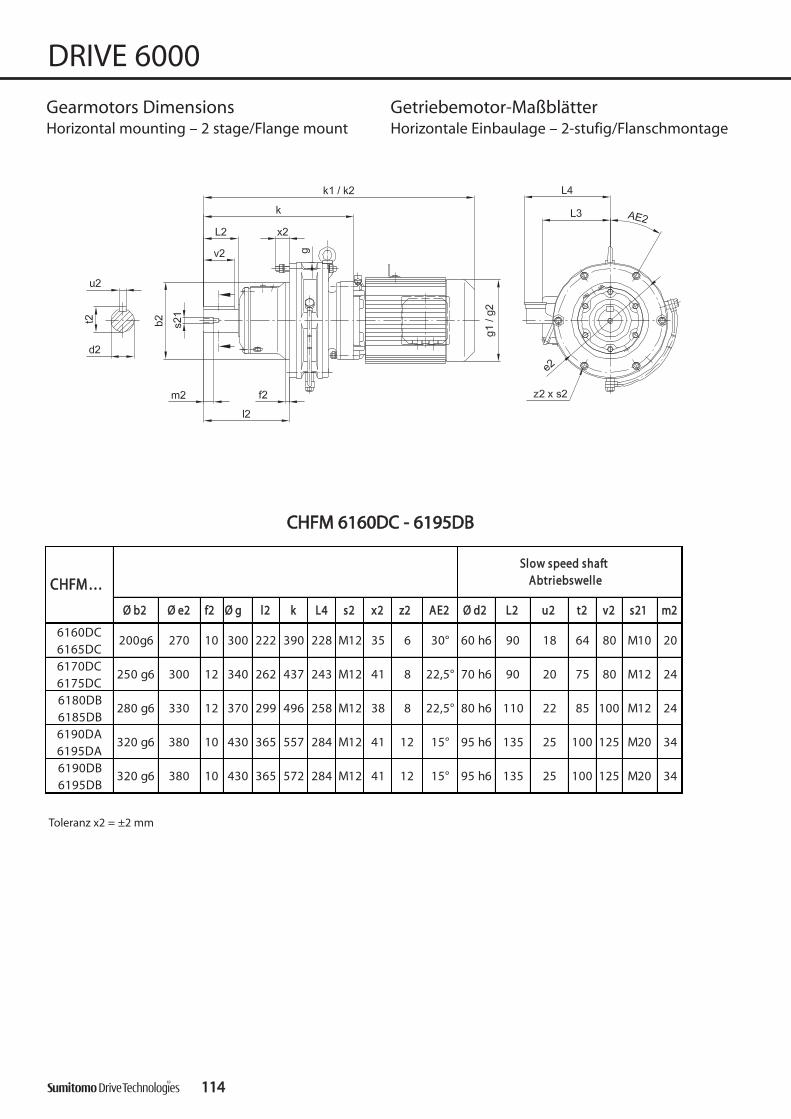
ØØ bb22 ØØ ee22 ff22 ØØ gg ll22 kk LL44 ss22 xx22 zz22 AAEE22 ØØ dd22 LL22 uu22 tt22 vv22 ss2211 mm22
6160DC6165DC6170DC6175DC6180DB6185DB6190DA6195DA6190DB6195DB
M20 34
390 228
437 243
496 258
557 284
135 25 100 12541 12 15° 95 h6365 M12572 284320 g6 380 10 430
34
200g6
135 25 100 12541
M1222 85
12 15° 95 h6
38 8 22,5° 80 h6299 M12 100
M20
24
320 g6 10380 430 365 M12
110
20
8 22,5° 70 h6 90 20 75 80 M12 24
280 g6 330 12 370
35270 10 300 6 30° 90 18 80
CCHHFFMM……
60 h6222 M12 64
SSllooww ssppeeeedd sshhaaffttAAbbttrriieebbsswweellllee
M10
41262 M12250 g6 300 12 340
CCHHFFMM 66116600DDCC -- 66119955DDBB
111144
DRIVE 6000
Gearmotors Dimensions Getriebemotor-MaßblätterHorizontal mounting – 2 stage/Flange mount Horizontale Einbaulage – 2-stufig/Flanschmontage
Toleranz x2 = ±2 mm

kk11 Ø gg11 LL33 kkgg kk22 Ø gg22 LL33 kkgg
2,2 F100L/4 680 173 155 92 743 173 155 993 F112S/44 F112M/4
5,5 F132S/4 747 109 819 119
0,37 F71M/4 641 124 128 106 670 124 128 1100,55 F80S/40,75 F80M/41,1 F90S/41,5 F90L/42,2 F100L/4 727 173 155 116 790 173 155 1233 F112S/44 F112M/4
5,5 F132S/4 794 133 866 1430,75 F80M/4 733 148 143 156 776 148 143 1591,1 F90S/41,5 F90L/42,2 F100L/4 786 173 155 161 849 173 155 1683 F112S/44 F112M/4
5,5 F132S/4 853 178 925 1887,5 F132M/4 876 193 971 21111 F160M/4 936 207 1031 225
0,55 F80S/40,75 F80M/41,1 F90S/41,5 F90L/42,2 F100L/4 847 173 155 208 910 173 155 2153 F112S/44 F112M/4
5,5 F132S/4 914 225 986 235
2,2 F100L/4 862 173 155 215 925 173 155 2223 F112S/44 F112M/4
5,5 F132S/4 929 232 1001 2427,5 F132M/4 952 247 1047 26511 F160M/4 1012 261 1107 27915 G160L/4 1102 324 261 313 1192 324 261 346
251 211
235225 957212 166
885212
251
166
211
143
148
166
203
209
228
837
889
942
148
160
212
143
148
166
200
204
218
793
827
870
148
160
212
211
166
148 165
181
828
881212
251
160
166
211
160
171
111
116
136822
148
160
212
143
148
166
108
111
126
717
769
112
674
707
750
148
160
212
143
148
166
102 775212 166
6180DB6185DB
703212 166
766
809
160
212
251
148
6190DA6195DA
6190DB6195DB
6160DC6165DC
wwiitthh bbrraakkee
mmiitt BBrreemmsseeSSttaannddaarrdd
kkWWIInnppuutt eelleemmeenntt
AAnnttrriieebbsszzuubbeehhöörrCCHHFFMM……
6170DC6175DC
111155
DRIVE 6000
Gea
rmot
or d
imen
sion
sG
etrie
bem
otor
-Maß
blä
tter
Gearmotors Dimensions Getriebemotor-MaßblätterHorizontal mounting – 2 stage/Flange mount Horizontale Einbaulage – 2-stufig/Flanschmontage
Keys and keyways according to DIN 6885 page 1Tolerances according to DIN ISO 286 part 2Where installation space is restricted, contact Sumitomo Drive Technologies for additional dimensions.
Passfedern nach DIN 6885 Seite 1Toleranzen nach DIN ISO 286 Teil 2Nicht tolerierte Maße sind bei beengter Einbausituation im Werk nachzufragen.

ØØ bb22 ØØ ee22 ff22 ØØ gg ll22 kk ss22 xx22 zz22 AAEE22 ØØ dd22 LL22 uu22 tt22 vv22 ss2211 mm22
6205DB 360 g6 405 20 448 410 624 M16 56 12 15° 100 h6 165 28 106 165 M20 34
6215DA 390 g6 440 20 485 423 651 M18 57 12 15° 110 h6 165 28 116 165 M20 34
6225DA 420 g6 475 20 526 454 693 M20 60 12 15° 120 h6 165 32 127 165 M20 34
6225DB 420 g6 475 20 526 454 735 M20 60 12 15° 120 h6 165 32 127 165 M20 34
CCHHFFMM……
SSllooww ssppeeeedd sshhaafftt
AAbbttrriieebbsswweellllee
CCHHFFMM 66220055DDBB -- 66222255DDBB
111166
DRIVE 6000
Gearmotors Dimensions Getriebemotor-MaßblätterHorizontal mounting – 2 stage/Flange mount Horizontale Einbaulage – 2-stufig/Flanschmontage
Toleranz x2 = ±2 mm

kk11 Ø gg11 LL33 kkgg kk22 Ø gg22 LL33 kkgg
0,75 F80M/4 861 148 143 237 904 148 143 2501,1 F90S/41,5 F90L/42,2 F100L/4 914 173 155 244 977 173 155 2513 F112S/44 F112M/4
5,5 F132S/4 981 261 1053 2717,5 F132M/4 1004 276 1099 29411 F160M/4 1064 289 1159 30715 G160L/4 1154 323 261 341 1234 323 261 373
0,75 F80M/4 887 148 143 316 930 148 143 3191,1 F90S/41,5 F90L/42,2 F100L/4 940 173 155 323 1003 173 155 3303 F112S/44 F112M/4
5,5 F132S/4 1007 340 1079 3507,5 F132M/4 1030 355 1125 37311 F160M/4 1090 368 1185 38615 G160L/4 1180 323 261 420 1270 323 261 453
1,1 F90S/41,5 F90L/42,2 F100L/4 982 173 155 380 1045 173 155 3873 F112S/44 F112M/4
5,5 F132S/4 1049 397 1121 4077,5 F132M/4 1072 412 1167 43011 F160M/4 1132 426 1227 44415 G160L/4 1222 323 261 478 1312 323 261 511
5,5 F132S/4 1107 212 166 442 1179 212 166 4527,5 F132M/4 1125 457 1220 47511 F160M/4 1185 471 1280 48915 G160L/4 1265 323 261 525 1355 323 261 558
18,5 F180MG/422 F180MG/430 F180L/4 610 661
593
251 211
1360 394 342
211251
6443423941570
211251211251
1077212 166
4001005212 166
390
1024 160 148 382963 160 148 377
211251211251
333166212
963 343166212
1035
982 160 148 325921 160 148 320
211251 211251
254937212 166
2641009212 166
241148160894 256148160956
wwiitthh bbrraakkee
mmiitt BBrreemmsseeSSttaannddaarrdd
kkWWIInnppuutt eelleemmeenntt
AAnnttrriieebbsszzuubbeehhöörr
6225DA
6225DB
CCHHFFMM……
6205DB
6245DA
111177
DRIVE 6000
Gea
rmot
or d
imen
sion
sG
etrie
bem
otor
-Maß
blä
tter
Gearmotors Dimensions Getriebemotor-MaßblätterHorizontal mounting – 2 stage/Flange mount Horizontale Einbaulage – 2-stufig/Flanschmontage
Keys and keyways according to DIN 6885 page 1Tolerances according to DIN ISO 286 part 2Where installation space is restricted, contact Sumitomo Drive Technologies for additional dimensions.
Passfedern nach DIN 6885 Seite 1Toleranzen nach DIN ISO 286 Teil 2Nicht tolerierte Maße sind bei beengter Einbausituation im Werk nachzufragen.

CCHHFFMM 66223355DDAA -- 66227755DDAA
ØØ bb22 ØØ ee22 ff22 ØØ gg ll22 kk ØØ ss22 xx22 zz22 AAEE22 ØØ dd22 LL22 uu22 tt22 vv22 ss2211 mm22
6235DA 455 g6 510 20 562 505 779 M20 63 12 15° 130 h6 200 32 137 200 M24 41
6245DA 500 g6 560 25 614 529 816 M24 65 12 15° 140 h6 200 36 148 200 M24 41
6255DA 540 g6 610 30 670 616 956 M24 91 12 15° 160 h6 240 40 169 240 M30 52
6265DA 570 g6 660 40 736 712 1088 M30 85 12 15° 170 h6 300 40 179 300 M30 52
6275DA 680 g6 820 50 950 919 1349 M30 85 12 15° 180 h6 330 45 190 330 M30 52
CCHHFFMM……
SSllooww ssppeeeedd sshhaafftt
AAbbttrriieebbsswweellllee
111188
DRIVE 6000
Gearmotors Dimensions Getriebemotor-MaßblätterHorizontal mounting – 2 stage/Flange mount Horizontale Einbaulage – 2-stufig/Flanschmontage

kk11 Ø gg11 LL33 kkgg kk22 Ø gg22 LL33 kkgg
2,2 F100L/4 1069 173 155 484 1131 173 155 490
3 F112S/4
4 F112M/4
5,5 F132S/4 1135 500 1207 510
7,5 F132M/4 1163 516 1258 53311 F160M/4 1223 530 1318 54715 G160L/4 1308 323 261 583 1398 323 261 616
18,5 F180MG/422 F180MG/42,2 F100L/4 1106 173 155 592 1169 173 155 5983 F112S/44 F112M/4
5,5 F132S/4 1173 608 1245 6187,5 F132M/4 1201 624 1296 64111 F160M/4 1261 638 1356 65515 G160L/4 1346 323 261 691 1436 323 261 724
18,5 F180MG/422 F180MG/4
3 F112S/44 F112M/4
5,5 F132S/4 1328 877 1400 8877,5 F132M/4 1346 892 1441 90711 F160M/4 1406 907 1501 92215 G160L/4 1486 323 261 957 1576 323 261 992
18,5 F180MG/422 F180MG/430 F180L/4 1047 10905,5 F132S/4 1480 212 166 1195 1552 212 166 12057,5 F132M/4 1493 1210 1588 123011 F160M/4 1553 1225 1648 124015 G160L/4 1618 323 261 1275 1708 323 261 1310
18,5 F180MG/4 39422 F180MG/430 F180L/4 1365 140837 F200L/445 F225S/6
5,5 F132S/4 1741 212 166 2185 1813 212 166 21957,5 F132M/4 1754 2195 1849 221511 F160M/4 1814 2210 1909 223015 G160L/4 1879 323 261 2265 1969 323 261 2305
18,5 F180MG/422 F180MG/430 F180L/4 2360 240337 F200L/445 F225S/6
342
342
342
342
211
2395
23302184
2304
394
6255DA
6265DA
CCHHFFMM……
6275DA
6235DA
6245DA
wwiitthh bbrraakkee
mmiitt BBrreemmsseeSSttaannddaarrdd
kkWWIInnppuutt eelleemmeenntt
AAnnttrriieebbsszzuubbeehhöörr
503
70734239416136563423941403
212
251
1091166 212 166
211251211
493 1163
1129212 166
601 1201212 166
611
1441
251
394 342 809
251 211211
758 1651 394 342
1581 394 3421027
1791 394 3421078
1284212 166
251 211
867212 166
211251
1356 877
1713
1828394
251 211
1400
13501923
2043
251
394
211
1395
1497
1974
2089
394
251 251
2492
211
2375
111199
DRIVE 6000
Gea
rmot
or d
imen
sion
sG
etrie
bem
otor
-Maß
blä
tter
Gearmotors Dimensions Getriebemotor-MaßblätterHorizontal mounting – 2 stage/Flange mount Horizontale Einbaulage – 2-stufig/Flanschmontage
Keys and keyways according to DIN 6885 page 1Tolerances according to DIN ISO 286 part 2Where installation space is restricted, contact Sumitomo Drive Technologies for additional dimensions.
Passfedern nach DIN 6885 Seite 1Toleranzen nach DIN ISO 286 Teil 2Nicht tolerierte Maße sind bei beengter Einbausituation im Werk nachzufragen.

ØØ aa22 ØØ bb22 cc22 ØØ ee22 ff22 ØØ gg ll22 kk ØØ ss22 zz22 AAEE22 ØØ dd22 LL22 uu22 tt22 vv vv22 ss2211 mm22
24
20
20
24
56
M10
M10
M12
M12
40
50
56
38,0
3,5
3,5
7
7
28,0
33,0
38,0
70
8
8
10
10
50
60
70
30°
25 k6
30 k6
35 k6
35 k6
45°
45°
30°
11
4
4
6
6
11
11
11
73
84
84
206
230
256
267
3
4
4
150
150
204
204
9
13
13
130
130
165
165200
110 j6
110 j6
130 j6
130 j6
M6 16
160 9 3 63
6 22,5 4 32
M5 16
160 110 j6 9 130 3 110 52 142
5 16,0 2,5 25
6120DAE6125DAE6120DBE6125DBE
30
11 4 45° 20 k6 40
160
200
6060DAE6065DAE6070DAE6075DAE6090DAE6095DAE6100DAE6105DAE
CCNNVVMM……
SSllooww ssppeeeedd sshhaafftt
AAbbttrriieebbsswweellllee
120 80 j6 8 100 3 110 39 131 9 6 30° 14 k6
From motor sizeab MotorgrößeF80S/4
CCNNVVMM 66006600DDAAEE -- 66112255DDBBEE
112200
DRIVE 6000
Gearmotors Dimensions Getriebemotor-MaßblätterUniversal mounting – 2 stage/Flange mount Beliebige Einbaulage – 2-stufig/Flanschmontage

kk11 Ø gg11 LL33 kkgg kk22 Ø gg22 LL33 kkgg
0,12 F63S/4 303 119 8 311 10
0,18 F63M/4 321 124 9 350 11
0,12 F63S/4 367 119 15 375 16
0,18 F63M/4
0,25 F63M/4
0,37 F71M/4 405 17 434 180,12 F63S/4 381 119 16 399 170,18 F63M/40,25 F63M/40,37 F71M/4 429 18 458 190,12 F63S/4 417 119 28 425 290,18 F63M/40,25 F63M/40,37 F71M/4 455 30 484 31
0,12 F63S/4 424 119 31 436 330,25 F63M/4 447 32 475 340,37 F71M/4 467 33 495 350,55 F80S/40,75 F80M/41,1 F90S/41,5 F90L/4
504
537 160 160
14854737148 40
124
41 599
143
148 46
128409
3012446429124
435
18124
385 124 1741416 128
10
124
124
128
119 8 124
124
124
128
128
128
143
148
128
300
128
128
128 43817
6120DB6125DB
CCNNVVMM……
6060DA6065DA
6070DA6075DA
6090DA6095DA
6100DA6105DA
6120DA6125DA
0,12 F63S/4 292
wwiitthh bbrraakkee
mmiitt BBrreemmsseeSSttaannddaarrdd
kkWWIInnppuutt eelleemmeenntt
AAnnttrriieebbsszzuubbeehhöörr
128 128
112211
DRIVE 6000
Gea
rmot
or d
imen
sion
sG
etrie
bem
otor
-Maß
blä
tter
Gearmotors Dimensions Getriebemotor-MaßblätterUniversal mounting – 2 stage/Flange mount Beliebige Einbaulage – 2-stufig/Flanschmontage
Keys and keyways according to DIN 6885 page 1Tolerances according to DIN ISO 286 part 2Where installation space is restricted, contact Sumitomo Drive Technologies for additional dimensions.
Passfedern nach DIN 6885 Seite 1Toleranzen nach DIN ISO 286 Teil 2Nicht tolerierte Maße sind bei beengter Einbausituation im Werk nachzufragen.

ØØ aa22 ØØ bb22 cc22 ØØ ee22 ff22 ØØ gg ll22 kk ØØ ss22 zz22 AAEE22 ØØ dd22 LL22 uu22 tt22 vv vv22 ss2211 mm22
20
30
80
M16
M10
80
64
10
0
53.5
90
14
18
100
0°
50 k6
60 h6
0°
11
6
6
11
89
348
3884
230
30020
230
310340
200 f8
270 f8
M16 30
260 15 4 106
14 53.5 10 80
M16 30
260 200 f8 15 230 4 230 106 348
14 53.5 10 80
6160DB6165DB
100
11 6 0° 50 k6 100
6130DBE6135DBE6130DCE6135DCE6140DCE6145DCE
CCHHVVMM……
SSllooww ssppeeeedd sshhaafftt
AAbbttrriieebbsswweellllee
260 200 f8 15 230 4 230 106 334 11 6 0° 50 k6
From motor sizeab MotorgrößeF80S/4
Only size/nur Größe6160DB, 6165DB
Only size/nur Größe6130DB - 6145DC
CCHHVVMM 66113300DDBBEE -- 66116655DDBB
112222
DRIVE 6000
Gearmotors Dimensions Getriebemotor-MaßblätterHorizontal mounting – 2 stage/Flange mount Horizontale Einbaulage – 2-stufig/Flanschmontage

kk11 Ø gg11 LL33 kkgg kk22 Ø gg22 LL33 kkgg
0,12 F63S/4 495 119 46 503 48
0,18 F63M/4
0,25 F63M/4
0,37 F71M/4 533 48 562 50
0,55 F80S/4
0,75 F80M/4
1,1 F90S/4
1,5 F90L/40,55 F80S/40,75 F80M/41,1 F90S/41,5 F90L/42,2 F100L/4 638 173 155 63 701 173 155 69
0,18 F63M/40,25 F63M/40,37 F71M/4 547 49 576 510,55 F80S/40,75 F80M/41,1 F90S/41,5 F90L/42,2 F100L/4 638 173 155 61 701 173 155 67
0,18 F63M/40,25 F63M/40,37 F71M/4 588 86 616 880,55 F80S/40,75 F80M/41,1 F90S/41,5 F90L/42,2 F100L/4 678 173 155 98 741 173 155 104
87
93
99
124
148
160
128
143
148
596
90
94
668
720
128
143
148
85568
625
658
124
148
160
128
143
148
50
56
62
556
628
680
124
148
160
128
143
148
48
53
57
527
585
618
124
148
160
143
148
56
62
628
680
148
160
128 49
618
585 148
160
143
148
53
57
143
148
55
61
542
614
666 160
148
124128
143
148 56
52
47513
604
571
124
148
160
6160DB6165DB
wwiitthh bbrraakkee
mmiitt BBrreemmsseeSSttaannddaarrdd
kkWWIInnppuutt eelleemmeenntt
AAnnttrriieebbsszzuubbeehhöörrCCHHVVMM……
6130DB6135DB
6130DC6130DC
6140DC6145DC
112233
DRIVE 6000
Gea
rmot
or d
imen
sion
sG
etrie
bem
otor
-Maß
blä
tter
Gearmotors Dimensions Getriebemotor-MaßblätterHorizontal mounting – 2 stage/Flange mount Horizontale Einbaulage – 2-stufig/Flanschmontage
Keys and keyways according to DIN 6885 page 1Tolerances according to DIN ISO 286 part 2Where installation space is restricted, contact Sumitomo Drive Technologies for additional dimensions.
Passfedern nach DIN 6885 Seite 1Toleranzen nach DIN ISO 286 Teil 2Nicht tolerierte Maße sind bei beengter Einbausituation im Werk nachzufragen.

ØØ aa22 ØØ bb22 cc22 ØØ ee22 ff22 ØØ gg ll22 LL44 kk ØØ ss22 zz22 AAEE22 ØØ dd22 LL22 uu22 tt22 vv22 ss2211 mm22
34
34
125
M20
M20
AAbbttrriieebbsswweellllee
90
430 345 f8
125
6180DB6185DB
SSllooww ssppeeeedd sshhaafftt
22 390 5 370 110 496 18
95 h6
15°
100
100
135
25
25
135557
572
8
18
12
12
18
110
30
450
450
80 h6
6
430
430
22,5°
145
30 6 145
490
400 f8
400 f8
80
2018 64 80 M10
M12 2420 74.590
6190DB6195DB
14 8 22,5°
6190DA6195DA
5 340 94
490
400
6160DC6165DC
6170DC6175DC
390 60 h6
316 f8
228
243
11
22 360
0°
437 70 h6
CCHHVVMM……
340 270 f8 20 310 4 300 89 6
258
284
284
2422 85 100 M12
15°
95 h6
CCHHVVMM 66116600DDCC -- 66119955DDBB
112244
DRIVE 6000
Gearmotors Dimensions Getriebemotor-MaßblätterHorizontal mounting – 2 stage/Flange mount Horizontale Einbaulage – 2-stufig/Flanschmontage

kk11 Ø gg11 LL33 kkgg kk22 Ø gg22 LL33 kkgg
2,2 F100L/4 680 173 155 106 743 173 155 113
3 F112S/44 F112M/4
5,5 F132S/4 747 126 819 136
0,37 F71M/4 641 124 128 129 670 122 128 131
0,55 F80S/4
0,75 F80M/4
1,1 F90S/41,5 F90L/42,2 F100L/4 727 173 155 141 790 173 155 1513 F112S/44 F112M/4
5,5 F132S/4 794 161 866 1710,75 F80M/4 733 148 143 175 776 148 143 1781,1 F90S/41,5 F90L/42,2 F100L/4 786 173 155 182 849 173 155 1893 F112S/44 F112M/4
5,5 F132S/4 853 199 925 2097,5 F132M/4 876 214 971 23211 F160M/4 936 228 1031 246
0,55 F80S/40,75 F80M/41,1 F90S/41,5 F90L/42,2 F100L/4 847 173 155 245 910 173 155 2523 F112S/44 F112M/4
5,5 F132S/4 914 262 986 272
2,2 F100L/4 862 173 155 252 925 173 155 2593 F112S/44 F112M/4
5,5 F132S/4 929 269 1001 2797,5 F132M/4 952 284 1047 30211 F160M/4 1012 298 1107 31615 G160L/4 1102 323 261 350 1192 323 261 383
6190DA6195DA
6170DC6175DC
6180DB6185DB
6190DB6195DB
CCHHVVMM……
6160DC6165DC
wwiitthh bbrraakkee
mmiitt BBrreemmsseeSSttaannddaarrdd
kkWWIInnppuutt eelleemmeenntt
AAnnttrriieebbsszzuubbeehhöörr
703212 166
116 775212 166
126
674
707
750
148
160
212
143
148
166
143
148
166
133
137
151
717
769
822
136
142
161
766 148 828 148
148
160
212
809
160
212
251
166
211
179
192 881
160
212
251
166
211
194
202
794
827
870
148
160
212
143
148
166
237
241
255
837
889
942
148
160
212
143
148
166
242
246
265
885212
251
166
211
166
211
272262 957212
251
112255
DRIVE 6000
Gea
rmot
or d
imen
sion
sG
etrie
bem
otor
-Maß
blä
tter
Gearmotors Dimensions Getriebemotor-MaßblätterHorizontal mounting – 2 stage/Flange mount Horizontale Einbaulage – 2-stufig/Flanschmontage
Keys and keyways according to DIN 6885 page 1Tolerances according to DIN ISO 286 part 2Where installation space is restricted, contact Sumitomo Drive Technologies for additional dimensions.
Passfedern nach DIN 6885 Seite 1Toleranzen nach DIN ISO 286 Teil 2Nicht tolerierte Maße sind bei beengter Einbausituation im Werk nachzufragen.

ØØ aa22 ØØ bb22 cc22 ØØ ee22 ff22 ØØ gg ll22 kk ØØ ss22 zz22 AAEE22 ØØ dd22 LL22 uu22 tt22 vv22 ss2211 mm22
6205DB 455 355 f8 30 405 5 448 204 624 22 8 0° 100 h6 165 28 106 165 M20 34
6215DA 490 390 f8 35 440 7 485 203 650 24 8 0° 110 h6 165 28 116 165 M20 34
6225DA 535 415 f8 35 475 10 526 210 692 27 8 0° 120 h6 165 32 127 165 M20 34
6225DB 535 415 f8 35 475 10 526 210 735 27 8 0° 120 h6 165 32 127 165 M20 34
CCHHVVMM……
SSllooww ssppeeeedd sshhaafftt
AAbbttrriieebbsswweellllee
CCHHVVMM 66220055DDBB -- 66222255DDBB
112266
DRIVE 6000
Gearmotors Dimensions Getriebemotor-MaßblätterHorizontal mount -2 stage/Flange mounting Horizontale Einbaulage – 2-stufig/Flanschmontage

kk11 Ø gg11 LL33 kkgg kk22 Ø gg22 LL33 kkgg
0,75 F80M/4 861 148 143 237 904 148 143 250
1,1 F90S/4
1,5 F90L/4
2,2 F100L/4 914 173 155 244 977 173 155 251
3 F112S/44 F112M/4
5,5 F132S/4 981 261 1053 2717,5 F132M/4 1004 276 1099 29411 F160M/4 1064 289 1159 30715 G160L/4 1154 323 261 341 1234 323 261 373
0,75 F80M/4 887 148 143 316 930 148 143 3191,1 F90S/41,5 F90L/42,2 F100L/4 940 173 155 323 1003 173 155 3303 F112S/44 F112M/4
5,5 F132S/4 1007 340 1079 3507,5 F132M/4 1030 355 1125 37311 F160M/4 1090 368 1185 38615 G160L/4 1180 323 261 420 1270 323 261 453
1,1 F90S/41,5 F90L/42,2 F100L/4 982 173 155 380 1045 173 155 3873 F112S/44 F112M/4
5,5 F132S/4 1049 397 1121 4077,5 F132M/4 1072 412 1167 43011 F160M/4 1132 426 1227 44415 G160L/4 1222 323 261 478 1312 323 261 511
5,5 F132S/4 1107 212 166 442 1179 212 166 4527,5 F132M/4 1125 457 1220 47511 F160M/4 1185 471 1280 48915 G160L/4 1265 323 261 525 1355 323 261 558
18,5 F180MG/422 F180MG/430 F180L/4 610 661
CCHHVVMM……
wwiitthh bbrraakkee
mmiitt BBrreemmsseeSSttaannddaarrdd
kkWWIInnppuutt eelleemmeenntt
AAnnttrriieebbsszzuubbeehhöörr
6205DB
6215DA
6225DA
6225DB
894
937
160
212
251
241
254 1009
956148
166
211
160
212264
251
256148
166
211
921
963
160
212
251
320
333
982
1035166
211
148 160 325
343
251
212
148
166
211
377
390
1024963
1005
160
212
148
1661077
160 382
400212 166
148
1360
251
394593
211
342
251
644
251
3941570
211
211
342
211 251
112277
DRIVE 6000
Gea
rmot
or d
imen
sion
sG
etrie
bem
otor
-Maß
blä
tter
Gearmotors Dimensions Getriebemotor-MaßblätterHorizontal mount -2 stage/Flange mounting Horizontale Einbaulage – 2-stufig/Flanschmontage
Keys and keyways according to DIN 6885 page 1Tolerances according to DIN ISO 286 part 2Where installation space is restricted, contact Sumitomo Drive Technologies for additional dimensions.
Passfedern nach DIN 6885 Seite 1Toleranzen nach DIN ISO 286 Teil 2Nicht tolerierte Maße sind bei beengter Einbausituation im Werk nachzufragen.

ØØ aa22 ØØ bb22 cc22 ØØ ee22 ff22 ØØ gg ll22 kk ØØ ss22 zz22 AAEE22 ØØ dd22 LL22 uu22 tt22 vv22 ss2211 mm22
6235DA 570 450 f8 40 510 10 562 250 779 27 8 0° 130 h6 200 32 137 200 M24 41
6245DA 635 485 f8 40 560 10 614 250 816 33 8 0° 140 h6 200 36 148 200 M24 41
6255DA 685 535 f8 45 610 10 670 295 956 33 8 0° 160 h6 240 40 169 240 M30 52
6265DA 750 570 f8 50 660 10 736 360 1088 39 8 0° 170 h6 300 40 179 300 M30 52
6275DA 1160 900 f8 60 1020 10 950 355 1349 39 8 22,5° 180 h6 330 45 190 330 M30 52
CCHHVVMM……
SSllooww ssppeeeedd sshhaafftt
AAbbttrriieebbsswweellllee
CCHHVVMM 66223355DDAA -- 66227755DDAA
112288
DRIVE 6000
Gearmotors Dimensions Getriebemotor-MaßblätterHorizontal mounting – 2 stage/Flange mount Horizontale Einbaulage – 2-stufig/Flanschmontage

kk11 Ø gg11 LL33 kkgg kk22 Ø gg22 LL33 kkgg
2,2 F100L/4 1068 173 155 522 1131 173 155 528
3 F112S/4
4 F112M/4
5,5 F132S/4 1135 538 1207 548
7,5 F132M/4 1163 554 1258 57111 F160M/4 1223 568 1318 58515 G160L/4 1308 323 261 621 1398 323 261 654
18,5 F180MG/422 F180MG/42,2 F100L/4 1106 173 155 616 1169 173 155 6223 F112S/44 F112M/4
5,5 F132S/4 1173 632 1245 6427,5 F132M/4 1201 648 1296 66511 F160M/4 1261 662 1356 67915 G160L/4 1346 323 261 715 1436 323 261 748
18,5 F180MG/422 F180MG/4
3 F112S/44 F112M/4
5,5 F132S/4 1328 953 1400 9637,5 F132M/4 1346 968 1441 98311 F160M/4 1406 982 1501 99715 G160L/4 1486 323 261 1040 1576 323 261 1075
18,5 F180MG/422 F180MG/430 F180L/4 1124 11675,5 F132S/4 1480 212 166 1295 1552 212 166 13057,5 F132M/4 1493 1308 1588 132811 F160M/4 1553 1325 1648 134015 G160L/4 1618 323 261 1375 1708 323 261 1410
18,5 F180MG/422 F180MG/430 F180L/4 1465 150837 F200L/445 F225S/6
5,5 F132S/4 1741 212 166 2685 1813 212 166 26957,5 F132M/4 1754 2693 1849 271311 F160M/4 1814 2707 1909 272215 G160L/4 1879 323 261 2760 1969 323 261 2795
18,5 F180MG/422 F180MG/430 F180L/4 2850 289337 F200L/445 F225S/6
6275DA
6235DA
6245DA
kkWWIInnppuutt eelleemmeenntt
AAnnttrriieebbsszzuubbeehhöörr
6255DA
6265DA
CCHHVVMM……
166
wwiitthh bbrraakkee
mmiitt BBrreemmsseeSSttaannddaarrdd
1092
1403 394 693
531212
211
342
166
211
342
211
342
211
342
166
211
342
166
211
342
166
211
342
251
166
211
342 1613 394 737
5411164
251
212
1129
1441
212
251
394
625
787 1651 394 840
6351201212
251
212
251
394
1284
1581
946
1105
956
1156
212
251
1356
1791 394
1828
1713
251
394
1450
1500
1923
2043
251
394
1593
1495
211
342
1974
2089
251
394
2835 2880
2978
251
3942184
23042885
211
342
112299
DRIVE 6000
Gea
rmot
or d
imen
sion
sG
etrie
bem
otor
-Maß
blä
tter
Gearmotors Dimensions Getriebemotor-MaßblätterHorizontal mounting – 2 stage/Flange mount Horizontale Einbaulage – 2-stufig/Flanschmontage
Keys and keyways according to DIN 6885 page 1Tolerances according to DIN ISO 286 part 2Where installation space is restricted, contact Sumitomo Drive Technologies for additional dimensions.
Passfedern nach DIN 6885 Seite 1Toleranzen nach DIN ISO 286 Teil 2Nicht tolerierte Maße sind bei beengter Einbausituation im Werk nachzufragen.

ØØ aa22 ØØ bb22 cc22 ØØ ee22 ff22 ØØ gg ll22 kk ØØ ss22 zz22 AAEE22 ØØ dd22 LL22 uu22 tt22 vv vv22 ss2211 mm22
6130DBE
6135DBE11 6 0° 50 k64 230 106 334260 200 f8 15 230
CCVVVVMM……
SSllooww ssppeeeedd sshhaafftt
AAbbttrriieebbsswweellllee
6130DCE6135DCE
6140DCE6140DCE
6160DB6165DB
91
11 6 0° 50 k6 91
200 f8
14 53,5 10,0 80 M16 30
260 200 f8 15 230 4 230 106 348 14 53,5 10 80 M16 30
260
340
15
20
4
4
106
89270 f8
230
310
230
300
348
388
6
6
11
11
50 k6
60 h6
0°
0° 64,0
14
18
91
80
80
80
30
20
M16
M10
10
0
53,5
Only size nur Größe6130DB - 6145DC
Only size nur Größe6160DB - 6165DB
From motor sizeab MotorgrößeF80S/4
CCVV VVMM 66113300DDBBEE -- 66116655DDBB
113300
DRIVE 6000
Gearmotors Dimensions Getriebemotor-MaßblätterVertical mounting – 2 stage/Flange mount Vertikale Einbaulage – 2-stufig/Flanschmontage

DRIVE 6000
kk11 Ø gg11 LL33 kkgg kk22 Ø gg22 LL33 kkgg
0,12 F63S/4 495 119 46 503 48
0,18 F63M/4
0,25 F63M/4
0,37 F71M/4 533 48 561 500,55 F80S/40,75 F80M/41,1 F90S/41,5 F90L/4
0,55 F80S/40,75 F80M/41,1 F90S/41,5 F90L/42,2 F100L/4 638 173 155 63 701 173 155 69
0,18 F63M/40,25 F63M/40,37 F71M/4 547 49 576 510,55 F80S/40,75 F80M/41,1 F90S/41,5 F90L/42,2 F100L/4 638 173 155 61 701 173 155 67
0,18 F63M/40,25 F63M/40,37 F71M/4 588 86 616 880,55 F80S/40,75 F80M/41,1 F90S/41,5 F90L/42,2 F100L/4 678 173 155 98 741 173 155 104
124
148
160
128
143
148
93
99
128
143
148
87
90
94
148
148
160
160720
85
668
124
48
53
57
50
56
62
128
143
148
124124
148
160
128
143
148
556
160
143
148
56
62160
143
148
53
57
49
55
61
148 148
160
148
124
148
143
128128
143
148
541
568
527
585
618
618
47
52
56
513
571
604
124
148
160
6140DC6145DC
625
658
614
666
628
680
628
680
596
6160DB6165DB
CCVVVVMM……
wwiitthh bbrraakkee
mmiitt BBrreemmsseeSSttaannddaarrdd
kkWWIInnppuutt eelleemmeenntt
AAnnttrriieebbsszzuubbeehhöörr
585
6130DB6135DB
6130DC6135DC
113311
Gea
rmot
or d
imen
sion
sG
etrie
bem
otor
-Maß
blä
tter
Gearmotors Dimensions Getriebemotor-MaßblätterVertical mounting – 2 stage/Flange mount Vertikale Einbaulage – 2-stufig/Flanschmontage
Keys and keyways according to DIN 6885 page 1Tolerances according to DIN ISO 286 part 2Where installation space is restricted, contact Sumitomo Drive Technologies for additional dimensions.
Passfedern nach DIN 6885 Seite 1Toleranzen nach DIN ISO 286 Teil 2Nicht tolerierte Maße sind bei beengter Einbausituation im Werk nachzufragen.

ØØ aa22 ØØ bb22 cc22 ØØ ee22 ff22 ØØ gg ll22 kk rr11 rr22 ØØ ss22 zz22 AAEE22 ØØ dd22 LL22 uu22 tt22 vv22 ss2211 mm22
6160DC6165DC
24
34
M12
M20
125
85
100
125
22
25
100
125
100
125
80 h6
95 h6
22,5°
15°
8
12
18
18
6 430
496
557
145 572
5
6
110
145
490 400 f8
390
450
30 450
430
490
22
30
370
430
345 f8
400 f8
75 80437 20
233 240
255 270
M12 24
20
400 316 f8 22 360 5 340 94
18 64 80 M1080
14 8 22,5° 70 h6 84
11 6 0° 60 h6
6170DC6175DC
6180DB6185DB
6190DA6195DA
6190DB6195DB
CCVVVVMM……
SSllooww ssppeeeedd sshhaafftt
AAbbttrriieebbsswweellllee
340 270 f8 20 310 4 300 89 390 196 200
218 225
255 270 M20 3425 10018 12 15° 95 h6
* Lubrication fittings may have different positions dependent on frame size.
Die Schmierarmaturen sind, je nach Getriebegröße, an verschiedenen Positionen. Bei Fettschmierung (untersetzungsabhängig) entfallen die Schmierarmaturen.
** Frame size 6190/6195 may use 2 pumps dependent on ratio.
Bei Größe 6190DA-6195DB sind, je nach Untersetzung, auch 2 Pumpen möglich.
CCVV VVMM 66116600DDCC -- 66119955DDBB
113322
DRIVE 6000
Gearmotors Dimensions Getriebemotor-MaßblätterVertical mounting – 2 stage/Flange mount Vertikale Einbaulage – 2-stufig/Flanschmontage

kk11 Ø gg11 LL33 kkgg kk22 Ø gg22 LL33 kkgg
2,2 F100L/4 680 173 155 106 743 173 155 1133 F112S/44 F112M/4
5,5 F132S/4 747 126 819 136
0,37 F71M/4 641 124 128 129 670 124 128 1310,55 F80S/40,75 F80M/41,1 F90S/41,5 F90L/42,2 F100L/4 727 173 155 141 790 173 155 1513 F112S/44 F112M/4
5,5 F132S/4 794 161 866 171
0,75 F80M/4 733 148 143 175 776 148 143 1781,1 F90S/41,5 F90L/42,2 F100L/4 786 173 155 182 849 173 155 1893 F112S/44 F112M/4
5,5 F132S/4 853 199 925 2097,5 F132M/4 876 214 971 23211 F160M/4 936 228 1031 246
0,55 F80S/40,75 F80M/41,1 F90S/41,5 F90L/42,2 F100L/4 847 173 155 245 910 173 155 2523 F112S/44 F112M/4
5,5 F132S/4 914 262 986 272
2,2 F100L/4 862 173 155 252 925 173 155 2593 F112S/44 F112M/4
5,5 F132S/4 929 269 1001 2797,5 F132M/4 952 284 1047 30211 F160M/4 1012 298 1107 31615 G160L/4 1102 323 261 350 1192 323 261 383
6180DB6185DB
6190DA6195DA
6190DB6195DB
CCVVVVMM……
6160DC6165DC
6170DC6175DC
wwiitthh bbrraakkee
mmiitt BBrreemmsseeSSttaannddaarrdd
kkWWIInnppuutt eelleemmeenntt
AAnnttrriieebbsszzuubbeehhöörr
703
674
707
750
794
827
870
775
717
769
822
837
889
942
212 166116
212 166126
212
160
148
166
148
143
151
133
137
148
160
212
143
148
166
136
142
161
766
809
160
212
251
148
166
211
179
192
828
881
251
148
166
211
194
202
148
160
237
241
143
148
160
212
212
143
148
166255
148
160
212 166
242
246
265
885212
251
166
211
166
211
272262 957212
251
113333
DRIVE 6000
Gea
rmot
or d
imen
sion
sG
etrie
bem
otor
-Maß
blä
tter
Gearmotors Dimensions Getriebemotor-MaßblätterVertical mounting – 2 stage/Flange mount Vertikale Einbaulage – 2-stufig/Flanschmontage
Keys and keyways according to DIN 6885 page 1Tolerances according to DIN ISO 286 part 2Where installation space is restricted, contact Sumitomo Drive Technologies for additional dimensions.
Passfedern nach DIN 6885 Seite 1Toleranzen nach DIN ISO 286 Teil 2Nicht tolerierte Maße sind bei beengter Einbausituation im Werk nachzufragen.

ØØ aa22 ØØ bb22 cc22 ØØ ee22 ff22 ØØ gg ll22 kk rr11 rr22 ØØ ss22 zz22 AAEE22 ØØ dd22 LL22 uu22 tt22 vv22 ss2211 mm22
6205DB 455 355 f8 30 405 5 448 204 624 341 287 22 8 0° 100 h6 165 28 106 165 M20 34
6215DA 490 390 f8 35 440 7 485 203 650 348 306 24 8 0° 110 h6 165 28 116 165 M20 34
6225DA 535 415 f8 35 475 10 526 210 692 352 326 27 8 0° 120 h6 165 32 127 165 M20 34
6225DB 535 415 f8 35 475 10 526 210 735 352 326 27 8 0° 120 h6 165 32 127 165 M20 34
CCVVVVMM……
SSllooww ssppeeeedd sshhaafftt
AAbbttrriieebbsswweellllee
ÃéÃ
ý
Ã
ý
Ã
:ì
;ì *ì
šîÃÎ
ì
+ì
@ì > 9ì
Õì
)ì
1ì 1í
’ì
(ì
<ìšì
9ìí
3ì
,ì8í 8ì
-í
-ì
1
-
CCVV VVMM 66220055DDBB -- 66222255DDBB
113344
DRIVE 6000
Gearmotors Dimensions Getriebemotor-MaßblätterVertical mounting – 2 stage/Flange mount Vertikale Einbaulage – 2-stufig/Flanschmontage

kk11 Ø gg11 LL33 kkgg kk22 Ø gg22 LL33 kkgg
0,75 F80M/4 861 148 143 266 904 148 143 269
1,1 F90S/4
1,5 F90L/4
2,2 F100L/4 914 173 155 273 977 173 155 2803 F112S/44 F112M/4
5,5 F132S/4 981 290 1053 3237,5 F132M/4 1004 305 1099 34611 F160M/4 1064 319 1159 36015 G160L/4 1154 323 261 371 1234 323 261 427
0,75 F80M/4 887 148 143 326 930 148 143 3291,1 F90S/41,5 F90L/42,2 F100L/4 940 173 155 333 1003 173 155 3403 F112S/44 F112M/4
5,5 F132S/4 1007 350 1079 3607,5 F132M/4 1030 365 1125 38311 F160M/4 1090 379 1185 39715 G160L/4 1180 323 261 431 1270 323 261 464
1,1 F90S/41,5 F90L/42,2 F100L/4 982 173 155 422 1045 173 155 4293 F112S/44 F112M/4
5,5 F132S/4 1049 439 1121 4497,5 F132M/4 1072 454 1167 47211 F160M/4 1132 468 1227 48515 G160L/4 1222 323 261 520 1312 323 261 552
5,5 F132S/4 1107 212 166 486 1179 212 166 4967,5 F132M/4 1125 500 1220 51811 F160M/4 1185 514 1280 53215 G160L/4 1265 323 261 568 1355 323 261 601
18,5 F180MG/422 F180MG/430 F180L/4 673 716
6561570
701394 3421360
251
394
211
342
211251
211251
424
442
160
212
148
166
419
432
1024
1077
251
148
166
211
962
1005
160
212
160
212
251
353
335
211
166
148330
343
982
1035
251
148
166
211
920
963
160
212
275
211
166293
160
212
251
148270
283
956
1009
894
937
160
212
251
148
166
211
6205DB
6215DA
6225DA
6225DB
CCVVVVMM……
wwiitthh bbrraakkee
mmiitt BBrreemmsseeSSttaannddaarrdd
kkWWIInnppuutt eelleemmeenntt
AAnnttrriieebbsszzuubbeehhöörr
113355
DRIVE 6000
Gea
rmot
or d
imen
sion
sG
etrie
bem
otor
-Maß
blä
tter
Gearmotors Dimensions Getriebemotor-MaßblätterVertical mounting – 2 stage/Flange mount Vertikale Einbaulage – 2-stufig/Flanschmontage
Keys and keyways according to DIN 6885 page 1Tolerances according to DIN ISO 286 part 2Where installation space is restricted, contact Sumitomo Drive Technologies for additional dimensions.
Passfedern nach DIN 6885 Seite 1Toleranzen nach DIN ISO 286 Teil 2Nicht tolerierte Maße sind bei beengter Einbausituation im Werk nachzufragen.

ØØ aa22 ØØ bb22 cc22 ØØ ee22 ff22 ØØ gg ll22 kk rr11 rr22 ØØ ss22 zz22 AAEE22 ØØ dd22 LL22 uu22 tt22 vv22 ss2211 mm22
6235DA 570 450 f8 40 510 10 562 250 779 359 344 27 8 0° 130 h6 200 32 137 200 M24 41
6245DA 635 485 f8 40 560 10 614 250 816 370 371 33 8 0° 140 h6 200 36 148 200 M24 41
6255DA 685 535 f8 45 610 10 670 295 956 395 399 33 8 0° 160 h6 240 40 169 240 M30 52
6265DA 750 570 f8 50 660 10 736 360 1088 427 431 39 8 0° 170 h6 300 40 179 300 M30 52
6275DA 1160 900 f8 60 1020 10 950 355 1347 610 613 39 8 22,5° 180 h6 320 45 190 320 M30 52
CCVVVVMM……
SSllooww ssppeeeedd sshhaafftt
AAbbttrriieebbsswweellllee
A-AX
A
X
A
only 6275DAnur 6275DA
t2
u2 d2
L3A
E2
e2
z2 x s2
I2c2
k2 k1
a2
b2
v2L2
s21
m2
f2r1 r2
g1
g2
k
g
CCVV VVMM 66223355DDAA -- 66227755DDAA
113366
DRIVE 6000
Gearmotors Dimensions Getriebemotor-MaßblätterVertical mounting – 2 stage/Flange mount Vertikale Einbaulage – 2-stufig/Flanschmontage

kk11 Ø gg11 LL33 kkgg kk22 Ø gg22 LL33 kkgg
2,2 F100L/4 1068 173 155 522 1131 173 155 528
3 F112S/44 F112M/4
5,5 F132S/4 1135 538 1207 548
7,5 F132M/4 1163 554 1258 57111 F160M/4 1223 568 1318 58515 G160L/4 1308 323 261 621 1398 323 261 654
18,5 F180MG/422 F180MG/42,2 F100L/4 1106 173 155 616 1169 173 155 6223 F112S/44 F112M/4
5,5 F132S/4 1173 632 1245 6427,5 F132M/4 1201 648 1296 66511 F160M/4 1261 662 1356 67915 G160L/4 1346 323 261 715 1436 323 261 748
18,5 F180MG/422 F180MG/4
3 F112S/4 1664 F112M/4 166
5,5 F132S/4 1328 953 1400 166 9637,5 F132M/4 1346 968 1441 211 98311 F160M/4 1406 982 1501 211 99715 G160L/4 1486 323 261 1040 1576 323 261 1075
18,5 F180MG/422 F180MG/430 F180L/4 1124 11675,5 F132S/4 1480 212 166 1295 1552 212 166 13057,5 F132M/4 1493 1308 1588 132811 F160M/4 1553 1325 1648 134015 G160L/4 1618 323 261 1375 1708 323 261 1410
18,5 F180MG/422 F180MG/430 F180L/4 1465 150837 F200L/445 F225S/6
5,5 F132S/4 1741 212 166 2685 1813 212 166 26957,5 F132M/4 1754 2693 1849 271311 F160M/4 1814 2707 1909 272215 G160L/4 1879 323 261 2760 1969 323 261 2795
18,5 F180MG/422 F180MG/430 F180L/4 2850 289337 F200L/445 F225S/6
wwiitthh bbrraakkee
mmiitt BBrreemmsseeSSttaannddaarrdd
kkWWIInnppuutt eelleemmeenntt
AAnnttrriieebbsszzuubbeehhöörr
6275DA
CCVVVVMM……
6235DA
6245DA
342
342
342
6255DA
6265DA
342
342
342
342
342
342
1613 394
166
211
1091
1403 394 693342 737
541166
211251
2121163
212
251
166
211
531
1129
1441
212
251
394
625
787
1201
1651
212
251
394
166
211
635
840
1284
1581
212
251
394
166
211
946
1105
1356
1791 394
212
251
956
1156
1828
1713
251
394
211
1450
1500 2043
1923
251
394
211
1593
1495
2089
1974
251
394
211
2885
2835
2304 2978
28802184
251
394
211
113377
DRIVE 6000
Gea
rmot
or d
imen
sion
sG
etrie
bem
otor
-Maß
blä
tter
Gearmotors Dimensions Getriebemotor-MaßblätterVertical mounting – 2 stage/Flange mount Vertikale Einbaulage – 2-stufig/Flanschmontage
Keys and keyways according to DIN 6885 page 1Tolerances according to DIN ISO 286 part 2Where installation space is restricted, contact Sumitomo Drive Technologies for additional dimensions.
Passfedern nach DIN 6885 Seite 1Toleranzen nach DIN ISO 286 Teil 2Nicht tolerierte Maße sind bei beengter Einbausituation im Werk nachzufragen.

113388
DRIVE 6000

113399
DRIVE 6000
Redu
cer S
elec
tion
Get
rieb
e A
usw
ahl
SSppeeeedd RReedduucceerr SSeelleeccttiioonn GGeettrriieebbee--AAuusswwaahhll

Ratio 3 and 5 not available for universal mounting.For vertical mounting please consult Sumitomo Drive Technologies.
Übersetzung 3 und 5 nicht verfügbar bei beliebiger Einbaulage.Bei Vertikalmontage bitte Rücksprache mit Sumitomo Drive Technologies.
nn11 == 558800 mmiinn--11
n2 [min-1] 193 116 96,7 72,5 52,7 44,6 38,7 34,1 27,6 23,2 20 16,6 13,5 11,4 9,83 8,17 6,67 4,87
Ratio 3 5 6 8 11 13 15 17 21 25 29 35 43 51 59 71 87 119
P1[kW] 0,2 0,192 0,139 0,118 0,102 0,09 0,073 0,061 0,053 0,044 0,036 - - - - - CNH 162
M2 [Nm] 18,8 24 24 24 24 24 24 24 24 24 24 - - - - - CNF 169FR2 [N] 796 811 957 1050 1170 1180 1180 1180 1180 1180 1180 - - - - - CNV 175
P1[kW] 0,267 0,216 0,174 0,148 0,128 0,113 0,091 0,077 0,066 0,055 0,045 - - - - - CNH 162
M2 [Nm] 25 27,1 30 30 30 30 30 30,0 30 30 30 - - - - - CNF 169FR2 [N] 796 811 957 1050 1170 1180 1180 1180 1180 1180 1180 - - - - - CNV 175
P1[kW] 0,316 0,288 0,262 0,221 0,192 0,169 0,137 0,115 0,099 0,082 0,067 0,056 0,049 - - - CNH 162
M2 [Nm] 29,7 36,1 45 45 45 45 45 45 45 45 45 45 45 - - - CNF 169FR2 [N] 1690 1770 1770 1770 1770 1770 1770 1770 1770 1770 1660 1550 1560 - - - CNV 175
P1[kW] 0,316 0,288 0,291 0,273 0,256 0,226 0,183 0,153 0,132 0,11 0,089 0,071 0,062 - - - CNH 162
M2 [Nm] 29,7 36,1 50,1 55,5 60 60 60 60 60 60 60 56,9 57,4 - - - CNF 169FR2 [N] 1690 1770 1770 1770 1770 1770 1770 1770 1770 1770 1660 1550 1560 - - - CNV 175
P1[kW] 0,592 0,592 0,465 0,393 0,341 0,301 0,235 0,205 0,176 0,146 0,119 0,1 0,087 0,072 0,059 - CNH 162
M2 [Nm] 55,6 74,1 80 80 80 80 77,2 80 80 80 80 80 80 80 80 - CNF 169FR2 [N] 2280 2440 2560 2560 2560 2560 2560 2560 2560 2560 2560 2560 2560 2560 2560 - CNV 175
P1[kW] 0,778 0,778 0,581 0,492 0,426 0,376 0,235 0,256 0,22 0,183 0,149 0,125 0,108 0,09 0,073 - CNH 162
M2 [Nm] 73 97,3 100 100 100 100 77,2 100 100 100 100 100 100 100 100 - CNF 169FR2 [N] 2280 2440 2560 2560 2560 2560 2560 2560 2560 2560 2560 2560 2560 2560 2560 - CNV 175
P1[kW] 1,15 1,15 0,872 0,738 0,639 0,564 0,457 0,384 0,331 0,274 0,223 0,186 0,158 0,119 0,11 0,058 CNH 162
M2 [Nm] 108 143 150 150 150 150 150 150 150 150 150 149 146 132 150 108 CNF 169FR2 [N] 3340 3340 3340 3240 3240 3240 3240 3340 3240 3240 3240 3340 3340 3340 3340 3340 CNV 175
P1[kW] 1,47 1,34 1,05 0,984 0,852 0,752 0,609 0,499 0,441 0,365 0,297 0,192 0,158 0,119 0,131 0,058 CNH 162
M2 [Nm] 138 168 181 200 200 200 200 195 200 200 200 153 146 132 178 108 CNF 169FR2 [N] 3340 3340 3340 3240 3240 3240 3240 3340 3240 3240 3240 3340 3340 3340 3340 3340 CNV 175
P1[kW] 1,82 1,82 1,82 1,86 1,45 1,23 1,07 0,94 0,761 0,639 0,551 0,457 0,372 0,313 0,271 0,225 0,184 0,134 CNH 162
M2 [Nm] 80 134 171 233 250 250 250 250 250 250 250 250 250 250 250 250 250 250 CNF 169FR2 [N] 4770 4770 4770 5300 5400 5400 5400 5400 5400 5400 5400 5400 5400 5120 4880 4680 4690 4660 CNV 175
P1[kW] 1,82 1,86 1,79 1,48 1,28 1,13 0,913 0,767 0,661 0,548 0,446 0,372 0,321 0,238 0,22 0,139 CNH 162
M2 [Nm] 171 233 308 300 300 300 300 300 300 300 300 297 296 264 300 258 CNF 169FR2 [N] 4770 5300 5400 5400 5400 5400 5400 5400 5400 5400 5400 5120 4880 4680 4690 4660 CNV 175
P1[kW] 2,06 2,88 2,09 1,77 1,53 1,35 1,1 0,921 0,794 0,658 0,535 0,451 0,39 0,324 0,265 - CNH 162
M2 [Nm] 193 360 360 360 360 360 360 360 360 360 360 360 360 360 360 - CNF 169FR2 [N] 5490 5940 6860 6830 6960 6760 6690 6430 6320 6380 6660 6660 6680 6640 6670 - CNV 175
P1[kW] 2,06 3,25 2,44 2,07 1,79 1,58 1,28 1,07 0,926 0,767 0,624 0,526 0,455 0,378 0,309 - CNH 162
M2 [Nm] 193 406 420 420 420 420 420 420 420 420 420 420 420 420 420 - CNF 169FR2 [N] 5490 5940 6860 6830 6960 6760 6690 6430 6320 6380 6660 6660 6680 6640 6670 - CNV 175
P1[kW] 3,27 3,27 3,9 4 3,05 2,58 2,24 1,96 1,59 1,34 1,15 0,959 0,781 0,658 0,569 0,473 0,386 - CNH 162
M2 [Nm] 145 241 366 501 525 525 525 520 522 525 520 525 525 525 525 525 525 - CNF 169FR2 [N] 5490 5490 6650 7260 7520 6740 6760 6740 6740 6740 6740 6740 6870 6740 6740 7610 6740 - CNV 175
P1[kW] 3,9 4 3,47 3,1 2,69 2,37 1,92 1,61 1,39 1,15 0,94 0,79 0,68 0,533 0,463 - CNH 162
M2 [Nm] 366 501 596 630 630 630 630 630 630 630 630 630 630 592 630 - CNF 169FR2 [N] 6650 7260 7520 6740 6760 6740 6740 6740 6740 6740 6870 6740 6740 7610 6740 - CNV 175
P1[kW] 6,47 6,47 5,91 5,94 4,53 3,84 3,32 2,93 2,37 1,99 1,72 1,42 1,16 1,16 0,99 0,813 0,623 - CHH 163
M2 [Nm] 286 476 555 744 780 780 780 780 780 780 780 780 780 928 912 902 848 - CHF 170FR2 [N] 6970 6970 6970 7780 8920 9370 9630 10400 11200 11700 12300 13000 13600 13300 14200 14300 14500 - CHV 175
P1[kW] 6,47 6,11 5,46 4,62 4,01 3,53 2,86 2,30 2,07 1,72 1,40 1,21 1,14 0,938 0,719 - CHH 163
M2 [Nm] 607 764 940 940 940 940 940 900 940 940 940 967 1050 1040 979 - CHF 170FR2 [N] 6970 7780 8920 9370 9630 10400 11200 11700 12300 13000 13600 13300 14200 14300 14500 - CHV 175
P1[kW] 7,45 7,45 7,64 7,8 7,12 6,02 5,22 4,61 3,73 3,13 2,70 2,24 1,82 1,54 1,33 1,10 0,9 - CHH 163
M2 [Nm] 329 549 717 976 1230 1230 1230 1230 1230 1230 1230 1230 1230 1230 1230 1230 1230 - CHF 170FR2 [N] 11600 11600 11600 12800 14400 14400 14500 14500 14700 14500 14200 14400 14100 14200 16000 16000 16000 - CHV 175
6140
6115
6120
6125
6130
6070
6075
6080
6135
PageSeite
6110
6090
6095
6100
6105
SizeGröße
6060
6065
6085
114400
DRIVE 6000
Speed Reducer Selection Getriebe-Auswahl
i = reduction ration2 = output speed [min-1]P1 = allowable input power [kW] M2 = allowable output power torque [Nm]FR2 = allowable radial load applied to mid of shaft end [N]
i = Übersetzungn2 = Abtriebsdrehzahl [min-1]P1 = Zulässige Antriebsleistung [kW] M2 = Zulässiges Abtriebsdrehmoment [Nm]FR2 = Zulässige Radialkraft auf Mitte Wellenende [N]
SSiinnggllee rreedduuccttiioonn ssppeeeedd rreedduucceerrss ii == 33 ttoo 111199The rating tables are based on a service factor fB1 of 1.0, i.e. 10 hours perday at uniform load.
EEiinnssttuuffiiggee GGeettrriieebbeeii == 33 bbiiss 111199Alle Angaben in den Auswahllisten gelten für einen Service Faktor fB1 von1,0, d.h. 10 Stunden pro Tag bei gleichförmiger Belastung.

nn11 == 558800 mmiinn--11
114411
DRIVE 6000
Redu
cer S
elec
tion
Get
rieb
e A
usw
ahl
Speed Reducer Selection Getriebe-Auswahl
i = reduction ration2 = output speed [min-1]P1 = allowable input power [kW] M2 = allowable output power torque [Nm]FR2 = allowable radial load applied to mid of shaft end [N]
i = Übersetzungn2 = Abtriebsdrehzahl [min-1]P1 = Zulässige Antriebsleistung [kW] M2 = Zulässiges Abtriebsdrehmoment [Nm]FR2 = Zulässige Radialkraft auf Mitte Wellenende [N]
SSiinnggllee rreedduuccttiioonn ssppeeeedd rreedduucceerrss ii == 33 ttoo 111199The rating tables are based on a service factor fB1 of 1.0, i.e.10 hours per day at uniform load.
EEiinnssttuuffiiggee GGeettrriieebbeeii == 33 bbiiss 111199Alle Angaben in den Auswahllisten gelten für einen ServiceFaktor fB1 von 1,0, d.h. 10 h/ Tag bei gleichförmiger Belastung.
Ratio 3 and 5 not available for universal mounting.For vertical mounting please consult Sumitomo Drive Technologies.
Übersetzung 3 und 5 nicht verfügbar bei beliebiger Einbaulage.Bei Vertikalmontage bitte Rücksprache mit Sumitomo Drive Technologies.
n2 [min-1] 193 116 96,7 72,5 52,7 44,6 38,7 34,1 27,6 23,2 20 16,6 13,5 11,4 9,83 8,17 6,67 4,87
Ratio 3 5 6 8 11 13 15 17 21 25 29 35 43 51 59 71 87 119
P1[kW] 7,64 7,8 7,51 6,74 5,79 5,15 4,07 3,5 3,02 2,5 2,04 1,72 1,48 1,19 0,917 - CHH 163
[Nm] 717 976 1290 1370 1360 1370 1340 1370 1370 1370 1370 1370 1370 1320 1250 - CHF 170
M2 11600 12800 14400 14400 14500 14500 14700 14500 14200 14400 14100 14200 16000 16000 16000 - CHV 175
P1[kW] 12,3 12,3 14,1 14 10,2 8,63 7,48 6,6 5,34 4,49 3,87 3,21 2,58 2,2 1,9 1,58 1,29 - CHH 164
M2 [Nm] 543 905 1320 1760 1760 1760 1760 1760 1760 1760 1760 1760 1740 1760 1760 1760 1760 - CHF 171FR2 [N] 13500 13500 13500 14900 17000 18000 19200 19900 21500 22100 22100 22100 22100 22100 22100 22100 21800 - CHV 177
P1[kW] 14,1 14,9 12,2 10,3 8,95 7,9 6,39 5,37 4,63 3,84 3,12 2,63 2,28 1,89 1,51 - CHH 164
M2 [Nm] 1320 1870 2100 2100 2100 2100 2100 2100 2100 2100 2100 2100 2100 2100 2050 - CHF 171FR2 [N] 13500 14900 17000 18000 19200 19900 21500 22100 22100 22100 22100 22100 22100 22100 21800 - CHV 177
P1[kW] 19,8 19,8 19,8 20,2 14,7 12,4 10,8 9,51 7,7 6,47 5,58 4,62 3,76 3,17 2,74 2,28 1,86 - CHH 164
M2 [Nm] 874 1457 1860 2530 2530 2530 2530 2530 2530 2530 2530 2530 2530 2530 2530 2530 2530 - CHF 171FR2 [N] 15100 15100 15100 16500 18900 19900 21000 22000 24100 25100 26600 28400 29500 29500 29500 29500 29500 - CHV 177
P1[kW] 19,8 20,8 18,3 15,5 13,4 11,8 9,59 8,06 6,94 5,75 4,68 3,95 3,41 2,84 2,31 - CHH 164
M2 [Nm] 1860 2600 3150 3150 3150 3150 3150 3150 3150 3150 3150 3150 3150 3150 3150 - CHF 171FR2 [N] 15100 16500 18900 19900 21000 22000 24100 25100 26600 28400 29500 29500 29500 29500 29500 - CHV 177
P1[kW] - - 23,6 20 17,3 15,3 12,3 10,4 8,93 7,4 6,03 5,08 4,39 3,65 2,98 - CHH 164
M2 [Nm] - - 4060 4060 4060 4060 4050 4050 4050 4050 4060 4050 4050 4050 4060 - CHF 171FR2 [N] - - 25200 26400 28300 29600 32200 33600 35300 37900 40800 41700 41600 41700 41700 - CHV 177
P1[kW] - - 27,9 24,1 19,9 18,8 15,2 12,8 11 9,13 7,43 6,27 5,42 4,06 3,67 - CHH 164
M2 [Nm] - - 4810 4900 4670 5000 5000 5000 5000 5000 5000 5000 5000 4510 5000 - CHF 171FR2 [N] - - 25200 26400 28000 29600 32200 33600 35300 37900 40800 41700 41600 41700 41700 - CHV 177
P1[kW] - - 37,1 31,4 27,2 24 19,4 16,3 14,1 11,7 9,49 8 6,91 5,74 4,69 - CHH 164
M2 [Nm] - - 6380 6380 6380 6380 6380 6380 6380 6380 6380 6380 6380 6380 6380 - CHF 171FR2 [N] - - 35100 36700 38600 41000 44600 46900 49500 52500 56700 58500 58100 58000 58400 - CHV 177
P1[kW] - - 44 36,1 33,2 29,9 24,2 20,4 17,5 14,5 11,8 9,98 8,63 7,17 5,85 - CHH 164
M2 [Nm] - - 7570 7350 7800 7960 7960 7960 7960 7960 7960 7960 7960 7960 7960 - CHF 171FR2 [N] - - 35100 36700 38600 41000 44600 46900 49500 52500 56700 58200 58100 58000 58400 - CHV 177
P1[kW] - - 46,8 - 39,5 - 28,2 - 20,3 - 13,8 - 10,1 - 6,43 - CHH 164
M2 [Nm] - - 8050 - 9270 - 9270 - 9230 - 9300 - 9300 - 8760 - CHF 171FR2 [N] - - 67300 - 72500 - 81600 - 84100 - 84100 - 84100 - 84100 - CHV 177
P1[kW] - - 64 - 51,9 - 38,1 - 27,9 - 18,8 - 13,7 - 8,28 - CHH 164
M2 [Nm] - - 11000 - 12200 - 12500 - 12700 - 12700 - 12700 - 11300 - CHF 171FR2 [N] - - 67300 - 72600 - 82500 - 90200 - 102000 - 104000 - 104000 - CHV 177
P1[kW] - - 74,7 - 61,7 - 45,1 - 33,2 - 23,8 - 17,2 - 11,1 - CHH 164
M2 [Nm] - - 12900 - 14500 - 14800 - 15000 - 16000 - 15900 - 15100 - CHF 171FR2 [N] - - 71100 - 77100 - 86900 - 95200 - 108000 - 118000 - 133000 - CHV 177
P1[kW] - - 99,9 - 83,6 - 57,5 - 41,7 - 30,5 - 22,2 - 12,6 - CHH 164
M2 [Nm] - - 17200 - 19600 - 18900 - 18900 - 20500 - 20500 - 17200 - CHF 171FR2 [N] - - 88800 - 95300 - 108000 - 119000 - 133000 - 146000 - 166000 - CHV 177
P1[kW] - - 117 - 112 - 78,5 - 56,9 - 38,4 - 28 - 16,6 - CHH 164
M2 [Nm] - - 20200 - 26200 - 25800 - 25800 - 25800 - 25800 - 22600 - CHF 171FR2 [N] - - 98600 - 106000 - 119000 - 131000 - 149000 - 163000 - 185000 - CHV 177
P1[kW] - - 151 - 133 - 94,4 - 71,6 - 51,3 - 37,4 - 22,8 - CHH 164
M2 [Nm] - - 25900 - 31200 - 31000 - 32500 - 34500 - 34500 - 31000 - CHF 171FR2 [N] - - 121000 - 130000 - 146000 - 161000 - 182000 - 200000 - 226000 - CHV 177
P1[kW] - - 175 - 175 - 140 - 101 - 68,4 - 49,8 - 32,3 - CHH 164
M2 [Nm] - - 30100 - 41000 - 46000 - 46000 - 46000 - 46000 - 44000 - CHF 171FR2 [N] - - 148000 - 158000 - 177000 - 197000 - 222000 - 243000 - 274000 - CHV 177
P1[kW] - - - - - - - - 150 - 101 - 73,9 - 50,1 - CHH 164
M2 [Nm] - - - - - - - - 68200 - 68200 - 68200 - 68200 - CHF 171FR2 [N] - - - - - - - - 228000 - 248000 - 248000 - 245000 - CHV 177
6215
6185
6190
6195
6205
6165
6170
6175
6145
PageSeite
6265
6275
6225
6235
6245
6255
SizeGröße
6160
6180

n2 [min-1] 240 144 120 90 65,5 55,4 48 42,4 34,3 28,8 24,8 20,6 16,7 14,1 12,2 10,1 8,28 6,05Ratio 3 5 6 8 11 13 15 17 21 25 29 35 43 51 59 71 87 119
P1[kW] 0,2 0,2 0,173 0,147 0,127 0,112 0,091 0,076 0,066 0,054 0,044 - - - - - CNH 162
M2 [Nm] 15,1 20,2 24 24 24 24 24 24 24 24 24 - - - - - CNF 169FR2 [N] 796 811 957 1050 1170 1180 1180 1180 1180 1180 1180 - - - - - CNV 175
P1[kW] 0,286 0,259 0,216 0,183 0,159 0,14 0,113 0,095 0,082 0,068 0,055 - - - - - CNH 162
M2 [Nm] 21,6 26,1 30 30 30 30 30 30 30 30 30 - - - - - CNF 169FR2 [N] 796 811 957 1050 1170 1180 1180 1180 1180 1180 1180 - - - - - CNV 175
P1[kW] 0,347 0,325 0,325 0,275 0,238 0,21 0,17 0,143 0,123 0,102 0,083 0,07 0,061 - - - CNH 162
M2 [Nm] 26,2 32,8 45 45 45 45 45 45 45 45 45 45 45 - - - CNF 169FR2 [N] 1570 1730 1770 1770 1770 1770 1770 1770 1770 1770 1660 1550 1560 - - - CNV 175
P1[kW] 0,376 0,325 0,344 0,322 0,317 0,28 0,227 0,19 0,164 0,136 0,111 0,089 0,077 - - - CNH 162
M2 [Nm] 28,4 32,8 47,7 52,7 60 60 60 60 60 60 60 56,9 57,4 - - - CNF 169FR2 [N] 1570 1730 1770 1770 1770 1770 1770 1770 1770 1770 1660 1550 1560 - - - CNV 175
P1[kW] 0,592 0,592 0,577 0,488 0,423 0,373 0,292 0,254 0,219 0,181 0,148 0,124 0,108 0,089 0,073 - CNH 162
M2 [Nm] 44,8 59,7 80 80 80 80 77,2 80 80 80 80 80 80 80 80 - CNF 169FR2 [N] 2140 2300 2530 2560 2560 2560 2560 2560 2560 2560 2560 2560 2560 2560 2260 - CNV 175
P1[kW] 0,778 0,778 0,683 0,61 0,529 0,467 0,292 0,317 0,274 0,227 0,185 0,156 0,135 0,112 0,091 - CNH 162
M2 [Nm] 58,8 78,4 94,7 100 100 100 77,2 100 100 100 100 100 100 100 100 - CNF 169FR2 [N] 2140 2300 2530 2560 2560 2560 2560 2560 2560 2560 2560 2560 2560 2560 2260 - CNV 175
P1[kW] 1,15 1,15 1,08 0,916 0,794 0,7 0,567 0,476 0,41 0,34 0,277 0,231 0,196 0,148 0,137 0,072 CNH 162
M2 [Nm] 86,7 116 150 150 150 150 150 150 150 150 150 149 146 132 150 108 CNF 169FR2 [N] 3340 3340 3340 3240 3240 3240 3240 3340 3240 3240 3240 3340 3340 3340 3340 3340 CNV 175
P1[kW] 1,52 1,52 1,24 1,19 1,06 0,934 0,756 0,588 0,547 0,453 0,369 0,239 0,196 0,148 0,154 0,072 CNH 162
M2 [Nm] 115 153 172 196 200 200 200 185 200 200 200 153 146 132 169 108 CNF 169FR2 [N] 3340 3340 3340 3240 3240 3240 3240 3340 3240 3240 3240 3340 3340 3340 3340 3340 CNV 175
P1[kW] 2,26 2,26 2,26 2,2 1,8 1,53 1,32 1,17 0,945 0,794 0,684 0,567 0,461 0,389 0,336 0,279 0,228 0,167 CNH 162
M2 [Nm] 80 134 171 222 250 250 250 250 250 250 250 250 250 250 250 250 250 250 CNF 169FR2 [N] 4430 4430 4430 4920 5400 5400 5400 5400 5400 5400 5400 5400 5400 5120 4880 4680 4690 4660 CNV 175
P1[kW] 2,26 2,2 2,22 1,83 1,59 1,4 1,13 0,952 0,821 0,68 0,554 0,462 0,398 0,295 0,274 0,172 CNH 162
M2 [Nm] 171 222 308 300 300 300 300 300 300 300 300 297 296 264 300 258 CNF 169FR2 [N] 4430 4920 5400 5400 5400 5400 5400 5400 5400 5400 5400 5120 4880 4680 4690 4660 CNV 175
P1[kW] 2,56 3,55 2,6 2,2 1,9 1,68 1,36 1,14 0,985 0,816 0,664 0,56 0,484 0,402 0,328 - CNH 162
M2 [Nm] 193 358 360 360 360 360 360 360 360 360 360 360 360 360 360 - CNF 169FR2 [N] 5100 5510 6350 6620 6960 6760 6690 6430 6320 6380 6660 6660 6680 6640 6670 - CNV 175
P1[kW] 2,56 3,92 3,03 2,56 2,22 1,96 1,59 1,33 1,15 0,952 0,775 0,654 0,565 0,469 0,383 - CNH 162
M2 [Nm] 193 395 420 420 420 420 420 420 420 420 420 420 420 420 420 - CNF 169FR2 [N] 5100 5510 6350 6620 6960 6760 6690 6430 6320 6380 6660 6660 6680 6640 6670 - CNV 175
P1[kW] 3,8 3,8 4,85 4,72 3,79 3,2 2,78 2,43 1,97 1,67 1,42 1,19 0,969 0,817 0,706 0,587 0,479 - CNH 162
M2 [Nm] 134 224 366 476 525 525 525 520 522 525 520 525 525 525 525 525 525 - CNF 169FR2 [N] 6160 6160 6160 6740 7480 7320 6760 6740 6740 6740 6740 6740 6870 6740 6740 7610 6740 - CNV 175
P1[kW] 4,85 4,72 4,09 3,69 3,33 2,94 2,38 2 1,72 1,43 1,16 0,98 0,847 0,661 0,575 - CNH 162
M2 [Nm] 366 476 567 605 630 630 630 630 630 630 630 630 630 592 630 - CNF 169FR2 [N] 6160 6740 7480 7320 6760 6740 6740 6740 6740 6740 6870 6740 6740 7610 6740 - CNV 175
P1[kW] 7,87 7,87 7,19 7,07 5,63 4,76 4,13 3,64 2,95 2,48 2,13 1,77 1,44 1,43 1,23 1,01 0,774 - CHH 163
M2 [Nm] 278 463 543 713 780 780 780 780 780 780 780 780 780 920 912 902 848 - CHF 170FR2 [N] 6450 6450 6450 7220 8240 8680 8920 9620 10300 10800 11400 12100 13200 13300 14200 14300 14500 - CHV 175
P1[kW] 7,87 7,27 6,78 5,74 4,97 4,39 3,55 2,86 2,57 2,13 1,73 1,49 1,41 1,16 0,893 - CHH 163
M2 [Nm] 595 733 940 940 940 940 940 900 940 940 940 959 1050 1040 979 - CHF 170FR2 [N] 6450 7220 8240 8680 8920 9620 10300 10800 11400 12100 13000 13300 14200 14300 14500 - CHV 175
P1[kW] 9,14 9,14 9,48 9,2 8,84 7,48 6,48 5,72 4,63 3,89 3,35 2,78 2,26 1,91 1,65 1,37 1,12 - CHH 163
M2 [Nm] 323 538 717 928 1230 1230 1230 1230 1230 1230 1230 1230 1230 1230 1230 1230 1230 - CHF 170FR2 [N] 10900 10900 10900 12000 13500 13800 14500 14500 14700 14500 14200 14400 14100 14200 16000 16000 16000 - CHV 175
PageSeite
6135
6140
6115
6120
6125
6130
SizeGröße
6060
6065
6085
6070
6075
6080
6110
6090
6095
6100
6105
nn11 == 772200 mmiinn--11
114422
DRIVE 6000
Speed Reducer Selection Getriebe-Auswahl
i = reduction ration2 = output speed [min-1]P1 = allowable input power [kW] M2 = allowable output power torque [Nm]FR2 = allowable radial load applied to mid of shaft end [N]
i = Übersetzungn2 = Abtriebsdrehzahl [min-1]P1 = Zulässige Antriebsleistung [kW] M2 = Zulässiges Abtriebsdrehmoment [Nm]FR2 = Zulässige Radialkraft auf Mitte Wellenende [N]
SSiinnggllee rreedduuccttiioonn ssppeeeedd rreedduucceerrss ii == 33 ttoo 111199The rating tables are based on a service factor fB1 of 1.0, i.e. 10 hours perday at uniform load.
EEiinnssttuuffiiggee GGeettrriieebbeeii == 33 bbiiss 111199Alle Angaben in den Auswahllisten gelten für einen Service Faktor fB1 von1,0, d.h. 10 Stunden pro Tag bei gleichförmiger Belastung.
Ratio 3 and 5 not available for universal mounting.For vertical mounting please consult Sumitomo Drive Technologies.
Übersetzung 3 und 5 nicht verfügbar bei beliebiger Einbaulage.Bei Vertikalmontage bitte Rücksprache mit Sumitomo Drive Technologies.

nn11 == 772200 mmiinn--11
n2 [min-1] 240 144 120 90 65,5 55,4 48 42,4 34,3 28,8 24,8 20,6 16,7 14,1 12,2 10,1 8,28 6,05Ratio 3 5 6 8 11 13 15 17 21 25 29 35 43 51 59 71 87 119
P1[kW] 9,48 9,2 9,32 8,36 7,18 6,4 5,06 4,35 3,75 3,11 2,53 2,13 1,84 1,48 1,14 - CHH 163
M2 [Nm] 717 928 1290 1370 1360 1370 1340 1370 1370 1370 1370 1370 1370 1320 1250 - CHF 170FR2 [N] 10900 12000 13500 13800 14500 14500 14700 14500 14200 14400 14100 14200 16000 16000 16000 - CHV 175
P1[kW] 14,3 14,3 17,5 17,4 12,7 10,7 9,29 8,19 6,63 5,57 4,8 3,98 3,2 2,73 2,36 1,96 1,6 - CHH 164
M2 [Nm] 505 842 1320 1760 1760 1760 1760 1760 1760 1760 1760 1760 1740 1760 1760 1760 1760 - CHF 171FR2 [N] 12500 12500 12500 13800 15800 16300 17700 18400 19900 21000 22000 22100 22100 22100 22100 22100 21800 - CHV 177
P1[kW] 17,5 17,8 15,2 12,8 11,1 9,8 7,94 6,67 5,75 4,76 3,88 3,27 2,82 2,35 1,87 - CHH 164
M2 [Nm] 1320 1790 2100 2100 2100 2100 2100 2100 2100 2100 2100 2100 2100 2100 2050 - CHF 171FR2 [N] 12500 13800 15800 16600 17700 18400 19900 21000 22000 22100 22100 22100 22100 22100 21800 - CHV 177
P1[kW] 24,6 24,6 24,6 25,1 18,3 15,4 13,4 11,8 9,56 8,03 6,92 5,74 4,67 3,94 3,4 2,83 2,31 - CHH 164
M2 [Nm] 869 1448 1860 2530 2530 2530 2530 2530 2530 2530 2530 2530 2530 2530 2530 2530 2530 - CHF 171FR2 [N] 13900 13900 13900 15200 17500 18400 19400 20400 22300 23300 24600 26300 28200 29500 29500 29500 29500 - CHV 177
P1[kW] 24,6 25,8 22,7 19,2 16,7 14,7 11,9 10 8,62 7,14 5,81 4,9 4,24 3,52 2,87 - CHH 164
M2 [Nm] 1860 2600 3150 3150 3150 3150 3150 3150 3150 3150 3150 3150 3150 3150 3150 - CHF 171FR2 [N] 13900 15200 17500 18400 19400 20400 22300 23300 24600 26300 28200 29500 29500 29500 29500 - CHV 175
P1[kW] - - 29,3 24,8 21,5 19 15,3 12,9 11,1 9,19 7,49 6,3 5,45 4,53 3,7 - CHH 164
M2 [Nm] - - 4060 4060 4060 4060 4050 4050 4050 4050 4060 4050 4050 4050 4060 - CHF 171FR2 [N] - - 23300 24400 26000 27400 29800 31300 32700 35100 37800 39400 41300 41700 41700 - CHV 177
P1[kW] - - 34,7 29,9 23,5 22,4 18,9 15,9 13,7 11,3 9,23 7,78 6,73 5,05 4,56 - CHH 164
M2 [Nm] - - 4810 4900 4440 4790 5000 5000 5000 5000 5000 5000 5000 4510 5000 - CHF 171FR2 [N] - - 23300 24400 26000 27400 29800 31200 32700 35100 37800 39400 41300 41700 41700 - CHV 177
P1[kW] - - 41 38,9 33,8 29,8 24,1 20,3 17,5 14,5 11,8 9,93 8,58 7,13 5,82 - CHH 164
M2 [Nm] - - 5680 6380 6380 6380 6380 6380 6380 6380 6380 6380 6380 6380 6380 - CHF 171FR2 [N] - - 32800 34100 35800 37900 41400 43500 45900 48700 52600 55000 57900 58000 58400 - CHV 177
P1[kW] - - 48,1 42,6 39,2 37,2 30,1 25,3 21,8 18 14,7 12,4 10,7 8,9 7,26 - CHH 164
M2 [Nm] - - 6670 6980 7410 7960 7960 7960 7960 7960 7960 7960 7960 7960 7960 - CHF 171FR2 [N] - - 32800 34100 35800 37900 41400 43500 45900 48700 52600 55000 57900 58000 58400 - CHV 177
P1[kW] - - 55,2 - 49 - 35 - 25,3 - 17,2 - 12,5 - 7,99 - CHH 164
M2 [Nm] - - 7650 - 9270 - 9270 - 9230 - 9300 - 9300 - 8760 - CHF 171FR2 [N] - - 63000 - 67800 - 76300 - 83600 - 84100 - 84100 - 84100 - CHV 177
P1[kW] - - 75,3 - 64,4 - 47,2 - 34,6 - 23,3 - 17 - 10,3 - CHH 164
M2 [Nm] - - 10400 - 12200 - 12500 - 12700 - 12700 - 12700 - 11300 - CHF 171FR2 [N] - - 63000 - 67900 - 77200 - 84400 - 95800 - 104000 - 104000 - CHV 177
P1[kW] - - 88,1 - 76,6 - 55,9 - 41,2 - 29,5 - 21,4 - 13,7 - CHH 164
M2 [Nm] - - 12200 - 14500 - 14800 - 15000 - 16000 - 15900 - 15100 - CHF 171FR2 [N] - - 66600 - 72100 - 81200 - 89000 - 101000 - 110000 - 124000 - CHV 177
P1[kW] - - 113 - 104 - 71,4 - 51,7 - 37,6 - 27,3 - 15,7 - CHH 164
M2 [Nm] - - 15700 - 19600 - 18900 - 18900 - 20400 - 20300 - 17200 - CHF 171FR2 [N] - - 83400 - 89000 - 101000 - 111000 - 125000 - 137000 - 155000 - CHV 177
P1[kW] - - 132 - 132 - 97,5 - 70,6 - 47,6 - 34,7 - 20,7 - CHH 164
M2 [Nm] - - 18300 - 24900 - 25800 - 25800 - 25800 - 25800 - 22600 - CHF 171FR2 [N] - - 92600 - 98800 - 112000 - 123000 - 139000 - 152000 - 173000 - CHV 177
P1[kW] - - 151 - 151 - 117 - 88,9 - 61,5 - 44,9 - 28,3 - CHH 164
M2 [Nm] - - 20900 - 28500 - 31000 - 32500 - 33300 - 33400 - 31000 - CHF 171FR2 [N] - - 114000 - 122000 - 136000 - 151000 - 170000 - 187000 - 211000 - CHV 177
P1[kW] - - 175 - 175 - 172 - 126 - 84,9 - 61,9 - 40,2 - CHH 164
M2 [Nm] - - 24200 - 33000 - 45400 - 46000 - 46000 - 46000 - 44000 - CHF 171FR2 [N] - - 140000 - 149000 - 166000 - 184000 - 208000 - 228000 - 257000 - CHV 177
P1[kW] - - - - - - - - 159 - 126 - 91,7 - 53,4 - CHH 164
M2 [Nm] - - - - - - - - 58100 - 68200 - 68200 - 58600 - CHF 171FR2 [N] - - - - - - - - 214000 - 248000 - 248000 - 240000 - CHV 177
PageSeite
6215
6185
6190
6195
6205
SizeGröße
6145
6160
6180
6165
6170
6175
6265
6275
6225
6235
6245
6255
114433
DRIVE 6000
Redu
cer S
elec
tion
Get
rieb
e A
usw
ahl
Speed Reducer Selection Getriebe-Auswahl
i = reduction ration2 = output speed [min-1]P1 = allowable input power [kW] M2 = allowable output power torque [Nm]FR2 = allowable radial load applied to mid of shaft end [N]
i = Übersetzungn2 = Abtriebsdrehzahl [min-1]P1 = Zulässige Antriebsleistung [kW] M2 = Zulässiges Abtriebsdrehmoment [Nm]FR2 = Zulässige Radialkraft auf Mitte Wellenende [N]
SSiinnggllee rreedduuccttiioonn ssppeeeedd rreedduucceerrss ii == 33 ttoo 111199The rating tables are based on a service factor fB1 of 1.0, i.e.10 hours per day at uniform load.
EEiinnssttuuffiiggee GGeettrriieebbeeii == 33 bbiiss 111199Alle Angaben in den Auswahllisten gelten für einen ServiceFaktor fB1 von 1,0, d.h. 10 h/ Tag bei gleichförmiger Belastung.
Ratio 3 and 5 not available for universal mounting.For vertical mounting please consult Sumitomo Drive Technologies.
Übersetzung 3 und 5 nicht verfügbar bei beliebiger Einbaulage.Bei Vertikalmontage bitte Rücksprache mit Sumitomo Drive Technologies.

nn11 == 998800 mmiinn--11
n2 [min-1] 327 196 163 123 89,1 75,4 65,3 57,6 46,7 39,2 33,8 28 22,8 19,2 16,6 13,8 11,3 8,24Ratio 3 5 6 8 11 13 15 17 21 25 29 35 43 51 59 71 87 119
P1[kW] 0,2 0,2 0,2 0,199 0,173 0,152 0,123 0,104 0,089 0,074 0,06 - - - - - CNH 162
M2 [Nm] 11,1 14,8 20,4 24 24 24 24 24 24 24 24 - - - - - CNF 169FR2 [N] 802 861 968 1050 1170 1180 1180 1180 1180 1180 1180 - - - - - CNV 175
P1[kW] 0,286 0,286 0,286 0,249 0,216 0,191 0,154 0,13 0,112 0,093 0,075 - - - - - CNH 162
M2 [Nm] 15,9 21,2 29,2 30 30 30 30 30 30 30 30 - - - - - CNF 169FR2 [N] 802 861 968 1050 1170 1180 1180 1180 1180 1180 1180 - - - - - CNV 175
P1[kW] 0,347 0,347 0,347 0,347 0,324 0,286 0,231 0,194 0,168 0,139 0,113 0,095 0,082 - - - CNH 162
M2 [Nm] 19,3 25,7 35,3 41,7 45 45 45 45 45 45 45 45 45 - - - CNF 169FR2 [N] 1420 1570 1730 1770 1770 1770 1770 1770 1770 1770 1660 1590 1620 - - - CNV 175
P1[kW] 0,407 0,386 0,407 0,407 0,404 0,381 0,309 0,245 0,223 0,185 0,151 0,119 0,101 - - - CNH 162
M2 [Nm] 22,6 28,6 41,4 49 56,1 60 60 56,8 60 60 60 56,4 55,1 - - - CNF 169FR2 [N] 1420 1570 1730 1770 1770 1770 1770 1770 1770 1770 1660 1590 1620 - - - CNV 175
P1[kW] 0,592 0,592 0,592 0,592 0,576 0,508 0,397 0,34 0,298 0,247 0,201 0,169 0,146 0,12 0,09 - CNH 162
M2 [Nm] 32,9 43,9 60,3 71,3 80 80 77,2 78,7 80 80 80 80 80 78,9 72,5 - CNF 169FR2 [N] 1940 2090 2290 2440 2530 2560 2560 2560 2500 2560 2560 2560 2560 2560 2560 - CNV 175
P1[kW] 0,778 0,778 0,778 0,778 0,72 0,635 0,397 0,432 0,372 0,309 0,251 0,212 0,183 0,152 0,121 - CNH 162
M2 [Nm] 43,2 57,6 79,2 93,6 100 100 77,2 100 100 100 100 100 100 100 97,6 - CNF 169FR2 [N] 1940 2090 2290 2440 2530 2560 2560 2560 2500 2560 2560 2560 2560 2560 2560 - CNV 175
P1[kW] 1,15 1,15 1,15 1,15 1,08 0,953 0,758 0,648 0,559 0,463 0,377 0,315 0,267 0,201 0,186 0,098 CNH 162
M2 [Nm] 63,7 84,9 117 138 150 150 147 150 150 150 150 149 146 132 150 108 CNF 169FR2 [N] 3340 3340 3340 3340 3240 3240 3340 3340 3340 3320 3340 3340 3340 3340 3340 3340 CNV 175
P1[kW] 1,52 1,52 1,52 1,51 1,44 1,27 1,03 0,745 0,698 0,61 0,471 0,325 0,267 0,201 0,195 0,098 CNH 162
M2 [Nm] 84,2 112 154 182 200 200 200 172 187 198 187 153 146 132 157 108 CNF 169FR2 [N] 3340 3340 3340 3340 3240 3240 3340 3340 3340 3320 3340 3340 3340 3340 3340 3340 CNV 175
P1[kW] 2,35 2,35 2,35 2,35 2,35 2,08 1,8 1,59 1,29 1,08 0,931 0,772 0,628 0,53 0,458 0,38 0,31 0,21 CNH 162
M2 [Nm] 62 103 130 174 239 250 250 250 250 250 250 250 250 250 250 250 250 231 CNF 169FR2 [N] 3980 3980 3980 4430 5000 5220 5400 5400 5400 5400 5400 5400 5400 5120 4880 4680 4690 4660 CNV 175
P1[kW] 3,02 2,78 2,86 2,49 2,16 1,91 1,54 1,3 1,12 0,926 0,754 0,629 0,53 0,402 0,372 0,235 CNH 162
M2 [Nm] 168 206 291 300 300 300 300 300 300 300 300 297 290 264 300 258 CNF 169FR2 [N] 3980 4430 5000 5220 5400 5400 5400 5400 5400 5400 5400 5120 4880 4680 4690 4660 CNV 175
P1[kW] 3,48 3,55 3,54 2,99 2,59 2,29 1,85 1,56 1,34 1,11 0,904 0,762 0,659 0,548 0,447 - CNH 162
M2 [Nm] 193 263 360 360 360 360 360 360 360 360 360 360 360 360 360 - CNF 169FR2 [N] 4580 5050 5710 5930 6360 6460 6690 6430 6320 6380 6660 6660 6680 6640 6670 - CNV 175
P1[kW] 3,48 3,92 3,92 3,49 3,02 2,67 2,16 1,81 1,56 1,3 1,06 0,89 0,769 0,639 0,521 - CNH 162
M2 [Nm] 193 290 399 420 420 420 420 420 420 420 420 420 420 420 420 - CNF 169FR2 [N] 4580 5050 5710 5930 6360 6460 6690 6430 6320 6380 6660 6660 6680 6640 6670 - CNV 175
P1[kW] 4,72 4,72 5,07 5,07 5,07 4,36 3,78 3,3 2,68 2,27 1,94 1,62 1,32 1,11 0,961 0,799 0,652 - CNH 162
M2 [Nm] 125 208 282 375 516 525 525 520 522 525 520 525 525 525 525 525 525 - CNF 169FR2 [N] 5530 5530 5530 6070 6740 7110 6760 6740 6740 6740 6740 6740 6870 6740 6740 8320 7150 - CNV 175
P1[kW] 6,4 5,97 5,18 4,68 4,54 4 3,24 2,72 2,35 1,94 1,58 1,33 1,15 0,843 0,761 - CNH 162
M2 [Nm] 355 442 527 563 630 630 630 630 630 630 630 630 630 554 613 - CNF 169FR2 [N] 5530 6070 6740 7110 6760 6740 6740 6740 6740 6740 6870 6740 6740 8320 7150 - CNV 175
P1[kW] 9,96 9,96 9,1 8,95 7,66 6,48 5,62 4,96 4,01 3,37 2,91 2,41 1,96 1,81 1,57 1,3 1,05 - CHH 163
M2 [Nm] 263 439 505 663 780 780 780 780 780 780 780 780 780 855 855 855 848 - CHF 170FR2 [N] 5800 5800 5800 6490 7360 7780 7980 8620 9270 9730 10300 10900 11700 12300 12900 13800 14500 - CHV 175
P1[kW] 9,96 9,2 9,23 7,58 6,77 5,97 4,84 3,89 3,5 2,9 2,36 1,89 1,81 1,5 1,22 - CHH 163
M2 [Nm] 553 682 940 912 940 940 940 900 940 940 940 892 987 987 979 - CHF 170FR2 [N] 5800 6490 7360 7780 7980 8620 9270 9730 10300 10900 11700 12300 12900 13800 14500 - CHV 175
P1[kW] 12,2 12,2 12,2 11,6 12 10,2 8,82 7,78 6,3 5,29 4,56 3,78 3,08 2,59 2,24 1,86 1,52 - CHH 163
M2 [Nm] 323 539 678 863 1230 1230 1230 1230 1230 1230 1230 1230 1230 1230 1230 1230 1230 - CHF 170FR2 [N] 9890 9890 9890 11000 12300 12500 13200 13800 14700 14500 14200 14400 14100 14500 16000 16000 16000 - CHV 175
PageSeite
6110
6090
6095
6100
6105
SizeGröße
6060
6065
6085
6070
6075
6080
6135
6140
6115
6120
6125
6130
114444
DRIVE 6000
Speed Reducer Selection Getriebe-Auswahl
i = reduction ration2 = output speed [min-1]P1 = allowable input power [kW] M2 = allowable output power torque [Nm]FR2 = allowable radial load applied to mid of shaft end [N]
i = Übersetzungn2 = Abtriebsdrehzahl [min-1]P1 = Zulässige Antriebsleistung [kW] M2 = Zulässiges Abtriebsdrehmoment [Nm]FR2 = Zulässige Radialkraft auf Mitte Wellenende [N]
SSiinnggllee rreedduuccttiioonn ssppeeeedd rreedduucceerrss ii == 33 ttoo 111199The rating tables are based on a service factor fB1 of 1.0, i.e. 10 hours perday at uniform load.
EEiinnssttuuffiiggee GGeettrriieebbeeii == 33 bbiiss 111199Alle Angaben in den Auswahllisten gelten für einen Service Faktor fB1 von1,0, d.h. 10 Stunden pro Tag bei gleichförmiger Belastung.
Ratio 3 and 5 not available for universal mounting.For vertical mounting please consult Sumitomo Drive Technologies.
Übersetzung 3 und 5 nicht verfügbar bei beliebiger Einbaulage.Bei Vertikalmontage bitte Rücksprache mit Sumitomo Drive Technologies.

DRIVE 6000
nn11 == 998800 mmiinn--11
n2 [min-1] 327 196 163 123 89,1 75,4 65,3 57,6 46,7 39,2 33,8 28 22,8 19,2 16,6 13,8 11,3 8,24Ratio 3 5 6 8 11 13 15 17 21 25 29 35 43 51 59 71 87 119
P1[kW] 12,2 11,6 12,1 11,4 9,78 8,71 6,88 5,92 5,1 4,23 3,44 2,74 2,36 1,94 1,55 - CHH 163
M2 [Nm] 678 863 1230 1370 1360 1370 1340 1370 1370 1370 1370 1290 1290 1280 1250 - CHF 170FR2 [N] 9890 11000 12300 12500 13200 13800 14700 14500 14200 14400 14100 14500 16000 16000 16000 - CHV 177
P1[kW] 17,8 17,8 20,3 19,7 17,2 14,6 12,6 11,2 9,03 7,58 6,54 5,42 4,36 3,72 3,21 2,67 2,18 - CHH 164
M2 [Nm] 472 786 1130 1460 1760 1760 1760 1760 1760 1760 1760 1760 1740 1760 1760 1760 1760 - CHF 171FR2 [N] 11300 11300 11100 12400 14100 14900 15900 16500 17800 18800 19700 21200 22100 22100 22100 22100 21800 - CHV 177
P1[kW] 23,8 22,5 20,6 17,4 15,1 13,3 10,8 9,07 7,82 6,48 5,28 4,45 3,84 3,19 2,55 - CHH 164
M2 [Nm] 1320 1670 2100 2100 2100 2100 2100 2100 2100 2100 2100 2100 2100 2100 2050 - CHF 171FR2 [N] 11100 12400 14100 14900 15900 16500 17800 18800 19700 21000 22100 22100 22100 22100 21800 - CHV 177
P1[kW] 30,1 30,1 27,6 27,6 24,8 21 18,2 16,1 13 10,9 9,42 7,81 6,36 5,36 4,63 3,85 3,14 - CHH 164
M2 [Nm] 798 1355 1530 2040 2530 2530 2530 2530 2530 2530 2530 2530 2530 2530 2530 2530 2530 - CHF 171FR2 [N] 12700 12700 12600 13800 15600 16400 17300 18200 20000 20800 22100 23600 25200 26500 27900 29500 29500 - CHV 177
P1[kW] 30,1 30,1 30,1 26,2 22,3 20 16,2 13,6 11,7 9,72 7,91 6,67 5,77 4,79 3,91 - CHH 164
M2 [Nm] 1670 2230 3070 3150 3100 3150 3150 3150 3150 3150 3150 3150 3150 3150 3150 - CHF 171FR2 [N] 12600 13800 15600 16400 17300 18200 20000 20800 22100 23600 25200 26500 27900 29500 29500 - CHV 177
P1[kW] - - 35,2 33,7 29,2 25,8 20,8 17,5 15,1 12,5 10,2 8,58 7,42 6,16 5,04 - CHH 164
M2 [Nm] - - 3580 4060 4060 4060 4050 4050 4050 4050 4060 4050 4050 4050 4060 - CHF 171FR2 [N] - - 21200 21900 23400 24700 26700 27900 29300 31500 33900 35400 37100 39800 41700 - CHV 177
P1[kW] - - 39 39 29,8 28,3 25,7 21,6 18,6 15,4 12,6 10,6 9,15 6,87 6,21 - CHH 164
M2 [Nm] - - 3970 4690 4130 4450 5000 5000 5000 5000 5000 5000 5000 4510 5000 - CHF 171FR2 [N] - - 21200 21900 23400 24700 26700 27900 29300 31500 33900 35400 37100 39800 41700 - CHV 177
P1[kW] - - 41 41 41 40,5 32,8 27,6 23,8 19,7 16 13,5 11,7 9,71 7,92 - CHH 164
M2 [Nm] - - 4180 4930 5690 6380 6380 6380 6380 6380 6380 6380 6380 6380 6380 - CHF 171FR2 [N] - - 30000 31000 32300 34100 37100 39000 41200 43700 47200 49400 52000 55300 58400 - CHV 177
P1[kW] - - 48,1 48,1 48,1 48,1 40,9 34,4 29,6 24,6 20 16,9 14,6 12,1 9,88 - CHH 164
M2 [Nm] - - 4900 5790 6680 7570 7960 7960 7960 7960 7960 7960 7960 7960 7960 - CHF 171FR2 [N] - - 30000 31000 32300 34100 37100 39000 41200 43700 47200 49400 52000 55300 58400 - CHV 177
P1[kW] - - 59,7 - 59,7 - 47,7 - 34,4 - 23,4 - 17 - 10,9 - CHH 164
M2 [Nm] - - 6080 - 8290 - 9270 - 9230 - 9300 - 9300 - 8760 - CHF 171FR2 [N] - - 57700 - 61800 - 69400 - 76000 - 84100 - 84100 - 84100 - CHV 177
P1[kW] - - 75,3 - 75,3 - 64,3 - 47,1 - 31,8 - 23,2 - 14 - CHH 164
M2 [Nm] - - 7670 - 10500 - 12500 - 12700 - 12700 - 12700 - 11300 - CHF 171FR2 [N] - - 58000 - 62000 - 70100 - 76600 - 87100 - 95100 - 104000 - CHV 177
P1[kW] - - 99,5 - 99,5 - 76,1 - 56 - 40,2 - 29,1 - 18,7 - CHH 164
M2 [Nm] - - 10100 - 13800 - 14800 - 15000 - 16000 - 15900 - 15100 - CHF 171FR2 [N] - - 61000 - 65500 - 73700 - 80800 - 91700 - 100000 - 113000 - CHV 177
P1[kW] - - 113 - 113 - 97,2 - 70,4 - 47,6 - 34,6 - 21,3 - CHH 164
M2 [Nm] - - 11500 - 15700 - 18900 - 18900 - 18900 - 18900 - 17200 - CHF 171FR2 [N] - - 76700 - 81700 - 91900 - 101000 - 114000 - 125000 - 141000 - CHV 177
P1[kW] - - 132 - 132 - 120 - 94,2 - 64,8 - 47,2 - 28,1 - CHH 164
M2 [Nm] - - 13400 - 18300 - 23300 - 25300 - 25800 - 25800 - 22600 - CHF 171FR2 [N] - - 85200 - 91100 - 102000 - 112000 - 126000 - 138000 - 157000 - CHV 177
P1[kW] - - 151 - 151 - 151 - 118 - 77,9 - 56,8 - 38,5 - CHH 164
M2 [Nm] - - 15300 - 20900 - 29300 - 31800 - 31000 - 31000 - 31000 - CHF 171FR2 [N] - - 104000 - 112000 - 124000 - 137000 - 155000 - 170000 - 192000 - CHV 177
P1[kW] - - 175 - 175 - 172 - 159 - 113 - 84,2 - 53,4 - CHH 164
M2 [Nm] - - 17800 - 24300 - 33400 - 42700 - 45000 - 46000 - 43000 - CHF 171FR2 [N] - - 128000 - 137000 - 152000 - 168000 - 189000 - 207000 - 234000 - CHV 177
P1[kW] - - - - - - - - 159 - 151 - 125 - 53,4 - CHH 164
M2 [Nm] - - - - - - - - 42700 - 60000 - 68200 - 43000 - CHF 171FR2 [N] - - - - - - - - 196000 - 248000 - 248000 - 219000 - CHV 177
PageSeite
6265
6275
6225
6235
6245
6255
SizeGröße
6145
6160
6180
6165
6170
6175
6215
6185
6190
6195
6205
114455
Redu
cer S
elec
tion
Get
rieb
e A
usw
ahl
Speed Reducer Selection Getriebe-Auswahl
i = reduction ration2 = output speed [min-1]P1 = allowable input power [kW] M2 = allowable output power torque [Nm]FR2 = allowable radial load applied to mid of shaft end [N]
i = Übersetzungn2 = Abtriebsdrehzahl [min-1]P1 = Zulässige Antriebsleistung [kW] M2 = Zulässiges Abtriebsdrehmoment [Nm]FR2 = Zulässige Radialkraft auf Mitte Wellenende [N]
SSiinnggllee rreedduuccttiioonn ssppeeeedd rreedduucceerrss ii == 33 ttoo 111199The rating tables are based on a service factor fB1 of 1.0, i.e.10 hours per day at uniform load.
EEiinnssttuuffiiggee GGeettrriieebbeeii == 33 bbiiss 111199Alle Angaben in den Auswahllisten gelten für einen ServiceFaktor fB1 von 1,0, d.h. 10 h/ Tag bei gleichförmiger Belastung.
Ratio 3 and 5 not available for universal mounting.For vertical mounting please consult Sumitomo Drive Technologies.
Übersetzung 3 und 5 nicht verfügbar bei beliebiger Einbaulage.Bei Vertikalmontage bitte Rücksprache mit Sumitomo Drive Technologies.

nn11 == 11445500 mmiinn--11
n2 [min-1]
483 290 242 181 132 112 96,7 85,5 69 58 50 41,4 33,7 28,4 24,6 20,4 16,7 12,2
Ratio 3 5 6 8 11 13 15 17 21 25 29 35 43 51 59 71 87 119
P1[kW] 0,2 0,2 0,2 0,2 0,2 0,2 0,183 0,11 0,11 0,11 0,089 - - - - - CNH 162
M2 [Nm] 7,51 10 13,8 16,3 18,8 21,3 24 17,2 20 24 24 - - - - - CNF 169
FR2 [N] 708 808 1070 1140 1180 1180 1180 1180 1180 1180 1180 - - - - - CNV 175
P1[kW] 0,286 0,286 0,286 0,286 0,286 0,282 0,228 0,166 0,165 0,137 0,112 - - - - - CNH 162
M2 [Nm] 10,7 14,3 19,7 23,3 26,9 30 30 25,9 30 30 30 - - - - - CNF 169
FR2 [N] 708 808 1070 1140 1180 1180 1180 1180 1180 1180 1180 - - - - - CNV 175
P1[kW] 0,347 0,347 0,347 0,347 0,347 0,347 0,32 0,23 0,226 0,205 0,167 0,1 0,1 - - - CNH 162
M2 [Nm] 13 17,3 23,9 28,2 32,5 36,9 42,1 35,9 41 45 45 31,9 36,9 - - - CNF 169
FR2 [N] 1260 1390 1550 1630 1630 1720 1710 1720 1710 1720 1660 1620 1600 - - - CNV 175
P1[kW] 0,407 0,407 0,407 0,407 0,407 0,407 0,407 0,294 0,286 0,272 0,223 0,143 0,136 - - - CNH 162
M2 [Nm] 15,3 20,4 28 33,1 38,2 43,3 53,5 46 52 59,6 60 45,7 50,1 - - - CNF 169
FR2 [N] 1260 1390 1550 1630 1630 1720 1710 1720 1710 1720 1660 1620 1600 - - - CNV 175
P1[kW] 0,592 0,592 0,592 0,592 0,592 0,592 0,478 0,34 0,34 0,34 0,25 0,192 0,185 0,12 0,09 - CNH 162
M2 [Nm] 22,2 29,6 40,8 48,2 55,6 63 62,9 53,2 61,7 74,5 67,3 61,3 68,1 53,3 49 - CNF 169
FR2 [N] 1720 1860 2040 2330 2400 2510 2510 2560 2560 2560 2560 2560 2560 2560 2560 - CNV 175
P1[kW] 0,778 0,778 0,778 0,778 0,778 0,778 0,55 0,475 0,467 0,412 0,294 0,241 0,234 0,202 0,121 - CNH 162
M2 [Nm] 29,2 38,9 53,5 63,3 73 82,7 72,3 74,3 84,8 90,2 79,1 76,9 86,2 89,7 66 - CNF 169
FR2 [N] 1720 1860 2040 2330 2400 2510 2510 2560 2560 2560 2560 2560 2560 2560 2560 - CNV 175
P1[kW] 1,15 1,15 1,15 1,15 1,15 1,15 0,758 0,671 0,625 0,612 0,435 0,332 0,309 0,252 0,211 0,125 CNH 162
M2 [Nm] 43 57,4 78,9 93,2 108 122 99,5 105 113 134 117 106 114 112 115 93,1 CNF 169
FR2 [N] 3340 3340 3340 3340 3340 3340 3310 3340 3340 3340 3340 3340 3340 3340 3340 3340 CNV 175
P1[kW] 1,52 1,52 1,52 1,52 1,52 1,52 1,51 0,866 0,784 0,758 0,603 0,407 0,336 0,278 0,263 0,145 CNH 162
M2 [Nm] 56,9 75,8 104 123 142 161 198 136 142 166 162 130 124 124 143 108 CNF 169
FR2 [N] 3340 3340 3340 3340 3340 3340 3310 3340 3340 3340 3340 3340 3340 3340 3340 3340 CNV 175
P1[kW] 3,18 3,18 2,35 2,35 2,35 2,35 2,35 1,99 1,9 1,27 1,21 0,975 0,78 0,56 0,516 0,436 0,433 0,21 CNH 162
M2 [Nm] 57 94 88,1 117 162 191 220 211 250 199 220 214 210 179 190 194 236 156 CNF 169
FR2 [N] 3530 3530 3530 3920 4430 4590 4830 4960 4970 4970 4970 4970 4970 4980 4910 4700 4700 4690 CNV 175
P1[kW] 3,18 3,18 3,18 3,18 3,18 2,46 2,28 1,67 1,59 1,2 1,08 0,776 0,681 0,506 0,503 0,286 CNH 162
M2 [Nm] 119 159 219 259 298 261 300 262 288 262 292 248 251 225 274 213 CNF 169
FR2 [N] 3530 3920 4430 4590 4830 4960 4970 4970 4970 4970 4970 4980 4910 4700 4700 4690 CNV 175
P1[kW] 3,55 3,55 3,55 3,55 3,55 3,18 2,72 1,91 1,9 1,5 1,3 0,944 0,859 0,669 0,661 - CNH 162
M2 [Nm] 133 178 244 289 333 338 358 299 346 329 350 301 317 297 360 - CNF 169
FR2 [N] 4040 4490 5100 5260 5580 5620 6000 6200 6330 6400 6670 6720 6730 6720 6680 - CNV 175
P1[kW] 3,92 3,92 3,92 3,9 3,9 3,9 3,11 2,22 2,22 1,81 1,52 1,11 1,01 0,758 0,758 - CNH 162
M2 [Nm] 147 196 270 317 366 415 409 348 403 396 408 355 373 337 412 - CNF 169
FR2 [N] 4040 4490 5100 5260 5580 5620 6000 6200 6330 6400 6670 6720 6730 6720 6680 - CNV 175
P1[kW] 6,21 6,21 5,07 5,07 5,07 5,07 5,07 4,89 3,96 3,09 2,87 2,37 1,91 1,63 1,3 0,957 0,944 - CNH 162
M2 [Nm] 110 183 190 254 349 412 476 520 520 483 520 520 515 520 482 425 514 - CNF 169
FR2 [N] 4910 4910 4910 5370 5970 6260 6560 6820 6740 7010 6740 6750 6870 6750 7470 9110 8240 - CNV 175
P1[kW] 6,96 6,95 5,92 5,92 5,92 5,66 4,79 3,96 3,47 2,88 2,34 1,97 1,62 1,14 1,03 - CNH 162
M2 [Nm] 261 348 407 482 556 602 630 619 630 630 630 630 598 506 559 - CNF 169
FR2 [N] 4910 5370 5970 6260 6560 6820 6740 7010 6740 6750 6870 6750 7470 9110 8240 - CNV 175
P1[kW] 11,3 11,3 9,39 9,39 9,39 9,39 7,78 7,27 5,94 4,99 4,3 3,56 2,9 2,44 2,11 1,76 1,42 - CHH 163
M2 [Nm] 199 332 353 470 646 764 731 774 780 780 780 780 780 780 780 780 772 - CHF 170
FR2 [N] 5160 5160 5160 5730 6500 6810 6990 7520 8100 8470 8960 9480 10200 10800 11300 12000 13000 - CHV 175
P1[kW] 11,3 11,3 11,3 10,2 8,97 8,29 6,72 5,75 4,88 4,11 3,35 2,55 2,44 2,03 1,65 - CHH 163
M2 [Nm] 424 566 778 832 842 882 883 900 886 900 900 813 900 900 900 - CHF 170
FR2 [N] 5160 5730 6500 6810 6990 7520 8100 8470 8960 9480 10200 10800 11300 12000 13000 - CHV 175
P1[kW] 15,1 15,1 13 13 13 13 12 10,1 8,66 6,89 5,95 5,21 3,94 3,43 2,96 2,43 1,98 - CHH 163
M2 [Nm] 267 445 489 652 896 1060 1130 1070 1140 1080 1080 1140 1060 1090 1090 1080 1080 - CHF 170
FR2 [N] 8810 8810 8810 9750 10900 11100 11600 12200 13100 13800 14100 14400 14600 14900 16000 16000 16000 - CHV 175
PageSeite
6135
6140
6115
6120
6125
6130
SizeGröße
6060
6065
6085
6070
6075
6080
6110
6090
6095
6100
6105
114466
DRIVE 6000
Speed Reducer Selection Getriebe-Auswahl
i = reduction ration2 = output speed [min-1]P1 = allowable input power [kW] M2 = allowable output power torque [Nm]FR2 = allowable radial load applied to mid of shaft end [N]
i = Übersetzungn2 = Abtriebsdrehzahl [min-1]P1 = Zulässige Antriebsleistung [kW] M2 = Zulässiges Abtriebsdrehmoment [Nm]FR2 = Zulässige Radialkraft auf Mitte Wellenende [N]
SSiinnggllee rreedduuccttiioonn ssppeeeedd rreedduucceerrss ii == 33 ttoo 111199The rating tables are based on a service factor fB1 of 1.0, i.e. 10 hours perday at uniform load.
EEiinnssttuuffiiggee GGeettrriieebbeeii == 33 bbiiss 111199Alle Angaben in den Auswahllisten gelten für einen Service Faktor fB1 von1,0, d.h. 10 Stunden pro Tag bei gleichförmiger Belastung.
Ratio 3 and 5 not available for universal mounting.For vertical mounting please consult Sumitomo Drive Technologies.
Übersetzung 3 und 5 nicht verfügbar bei beliebiger Einbaulage.Bei Vertikalmontage bitte Rücksprache mit Sumitomo Drive Technologies.

nn11 == 11445500 mmiinn--11
n2 [min-1] 483 290 242 181 132 112 96,7 85,3 69 58 50 41,4 33,7 28,4 24,6 20,4 16,7 12,2Ratio 3 5 6 8 11 13 15 17 21 25 29 35 43 51 59 71 87 119
P1[kW] 15,1 15,1 15,1 15,1 14,5 12 9,49 7,91 7,53 6,26 4,67 3,7 3,18 2,62 2,16 - CHH 163
M2 [Nm] 569 758 1040 1230 1360 1280 1250 1240 1370 1370 1260 1180 1170 1160 1170 - CHF 170FR2 [N] 8810 9750 10900 11100 11600 12200 13100 13800 14100 14400 14600 14900 16000 16000 16000 - CHV 175
P1[kW] 23,4 23,4 20,3 19,7 19,7 19,7 18,7 13,1 12,9 9,86 9,56 8,01 6,45 5,5 4,42 3,47 3,22 - CHH 164
M2 [Nm] 413 689 762 986 1360 1600 1760 1390 1700 1540 1740 1760 1740 1760 1630 1540 1760 - CHF 171FR2 [N] 10100 10100 9990 11100 12500 13100 13800 14300 15500 16300 17100 18300 19600 20600 22100 22100 21800 - CHV 177
P1[kW] 24,1 24,1 24,1 22,6 22,4 18,8 16 13,4 11,4 9,59 7,81 6,58 5,69 4,73 3,77 - CHH 164
M2 [Nm] 903 1200 1660 1840 2100 2000 2100 2100 2070 2100 2100 2100 2100 2100 2050 - CHF 171FR2 [N] 9990 11100 12500 13100 13800 14300 15500 16300 17100 18300 19600 20600 22100 22100 21800 - CHV 177
P1[kW] 30,1 30,1 27,6 27,6 27,6 27,3 25,5 19,7 18,6 15,6 13,5 11,2 9,08 7,66 6,62 5,5 4,57 - CHH 164
M2 [Nm] 530 883 1040 1380 1900 2220 2390 2090 2440 2440 2440 2440 2440 2440 2440 2450 2490 - CHF 171FR2 [N] 11300 11300 11300 12400 14100 14600 15100 16100 17300 18100 19200 20500 22000 23000 24300 25800 27800 - CHV 177
P1[kW] 30,1 30,1 30,1 30,1 30,1 24,1 23,6 19,5 17,4 14,4 11,3 9,87 8,29 6,98 5,62 - CHH 164
M2 [Nm] 1130 1510 2070 2450 2820 2560 3100 3050 3150 3150 3040 3150 3060 3100 3060 - CHF 171FR2 [N] 11300 12400 14100 14600 15100 16100 17300 18100 19200 20500 22000 23000 24300 25800 27800 - CHV 177
P1[kW] - - 35,2 35,2 32,4 30,6 30 24,1 19,5 18,5 15,1 12 9,75 8,8 7,15 - CHH 164
M2 [Nm] - - 2420 2860 3040 3250 3940 3760 3540 4050 4050 3830 3600 3910 3890 - CHF 171FR2 [N] - - 19000 19600 20500 21600 23200 24400 25800 27500 29500 30900 32500 34800 37400 - CHV 177
P1[kW] - - 39 39 39 38,2 38,1 30,1 24,1 22,6 18,6 15,1 12 9,79 8,59 - CHH 164
M2 [Nm] - - 2680 3170 3660 4060 5000 4710 4360 4950 5000 4810 4430 4350 4680 - CHF 171FR2 [N] - - 19000 19600 20500 21600 23200 24400 25800 27500 29500 30900 32500 34800 37400 - CHV 177
P1[kW] - - 41 41 41 41 41 35,2 30,7 24,3 20,9 18,2 15,3 13,5 11,7 - CHH 164
M2 [Nm] - - 2820 3330 3850 4360 5390 5500 5570 5320 5640 5800 5640 6000 6380 - CHF 171FR2 [N] - - 26700 27600 28900 30500 32700 34400 36200 38400 41400 43500 45700 48500 52300 - CHV 177
P1[kW] - - 48,1 48,1 48,1 48,1 48,1 40,5 37,8 30,1 27,1 20,9 18,8 15,6 13,6 - CHH 164
M2 [Nm] - - 3310 3910 4510 5120 6320 6330 6860 6600 7300 6680 6950 6930 7420 - CHF 171FR2 [N] - - 26700 27600 28900 30500 32700 34400 36200 38400 41400 43500 45700 48500 52300 - CHV 177
P1[kW] - - 59,7 - 59,7 - 59,2 - 45,7 - 31,8 - 22,6 - 15,9 - CHH 164
M2 [Nm] - - 4110 - 5600 - 7780 - 8280 - 8550 - 8340 - 8650 - CHF 171FR2 [N] - - 51700 - 55400 - 61800 - 67500 - 76500 - 83500 - 84100 - CHV 177
P1[kW] - - 75,3 - 75,3 - 75,3 - 58,5 - 45,2 - 33,9 - 19,7 - CHH 164
M2 [Nm] - - 5190 - 7070 - 9900 - 10600 - 12200 - 12500 - 10700 - CHF 171FR2 [N] - - 52000 - 55700 - 62600 - 68300 - 77200 - 84200 - 95400 - CHV 177
P1[kW] - - 99,5 - 99,5 - 94,2 - 75,3 - 56,5 - 39,3 - 26,7 - CHH 164
M2 [Nm] - - 6850 - 9330 - 12400 - 13700 - 15200 - 14500 - 14600 - CHF 171FR2 [N] - - 54800 - 59000 - 65700 - 71800 - 81300 - 89000 - 100000 - CHV 177
P1[kW] - - - - - - - - - - - - - - - - CHH 164
M2 [Nm] - - - - - - - - - - - - - - - - CHF 171FR2 [N] - - - - - - - - - - - - - - - - CHV 177
P1[kW] - - - - - - - - - - - - - - - - CHH 164
M2 [Nm] - - - - - - - - - - - - - - - - CHF 171FR2 [N] - - - - - - - - - - - - - - - - CHV 177
P1[kW] - - - - - - - - - - - - - - - - CHH 164
M2 [Nm] - - - - - - - - - - - - - - - - CHF 171FR2 [N] - - - - - - - - - - - - - - - - CHV 177
P1[kW] - - - - - - - - - - - - - - - - CHH 164
M2 [Nm] - - - - - - - - - - - - - - - - CHF 171FR2 [N] - - - - - - - - - - - - - - - - CHV 177
P1[kW] - - - - - - - - - - - - - - - - CHH 164
M2 [Nm] - - - - - - - - - - - - - - - - CHF 171FR2 [N] - - - - - - - - - - - - - - - - CHV 177
6275
6225
6235
6245
6255
6170
6175
6145
6265
PageSeite
6215
6185
6190
6195
6205
SizeGröße
6160
6180
6165
114477
DRIVE 6000
Redu
cer S
elec
tion
Get
rieb
e A
usw
ahl
Speed Reducer Selection Getriebe-Auswahl
i = reduction ration2 = output speed [min-1]P1 = allowable input power [kW] M2 = allowable output power torque [Nm]FR2 = allowable radial load applied to mid of shaft end [N]
i = Übersetzungn2 = Abtriebsdrehzahl [min-1]P1 = Zulässige Antriebsleistung [kW] M2 = Zulässiges Abtriebsdrehmoment [Nm]FR2 = Zulässige Radialkraft auf Mitte Wellenende [N]
SSiinnggllee rreedduuccttiioonn ssppeeeedd rreedduucceerrss ii == 33 ttoo 111199The rating tables are based on a service factor fB1 of 1.0, i.e.10 hours per day at uniform load.
EEiinnssttuuffiiggee GGeettrriieebbeeii == 33 bbiiss 111199Alle Angaben in den Auswahllisten gelten für einen ServiceFaktor fB1 von 1,0, d.h. 10 h/ Tag bei gleichförmiger Belastung.
Ratio 3 and 5 not available for universal mounting.For vertical mounting please consult Sumitomo Drive Technologies.
Übersetzung 3 und 5 nicht verfügbar bei beliebiger Einbaulage.Bei Vertikalmontage bitte Rücksprache mit Sumitomo Drive Technologies.

n2 [min-1] 483 363 264 223 193 171 138 116 100 83 67 57 49 41 33 24Ratio 6 8 11 13 15 17 21 25 29 35 43 51 59 71 87 119
P1[kW] 0,2 0,2 0,2 0,2 0,2 0,2 0,183 0,11 0,11 0,11 0,089 - - - - - CNH 162
M2 [Nm] 3,8 5 6,9 8,1 9,4 10,6 12 8,6 10 12 12 - - - - - CNF 169FR2 [N] 567 648 880 1020 1180 1180 1180 1180 1180 1180 1180 - - - - - CNV 175
P1[kW] 0,286 0,286 0,286 0,286 0,286 0,282 0,228 0,166 0,165 0,137 0,112 - - - - - CNH 162
M2 [Nm] 5,4 7,2 9,8 11,6 13,4 15 15 13 15 15 15,1 - - - - - CNF 169FR2 [N] 567 648 880 1020 1180 1180 1180 1180 1180 1180 1180 - - - - - CNV 175
P1[kW] 0,347 0,347 0,347 0,347 0,347 0,347 0,32 0,23 0,226 0,205 0,167 0,1 0,1 - - - CNH 162
M2 [Nm] 6,5 8,7 11,9 14,1 16,3 18,5 21 18 20,5 22,4 22,5 16 18,5 - - - CNF 169FR2 [N] 1020 1120 1250 1320 1330 1400 1410 1400 1400 1410 1410 1390 1470 - - - CNV 175
P1[kW] 0,407 0,407 0,407 0,407 0,407 0,407 0,407 0,294 0,286 0,272 0,223 0,143 0,136 - - - CNH 162
M2 [Nm] 7,6 10,2 14 16,6 19,1 21,6 26,7 23 25,9 29,8 30 22,8 25,1 - - - CNF 169FR2 [N] 1020 1120 1250 1320 1330 1400 1410 1400 1400 1410 1410 1390 1470 - - - CNV 175
P1[kW] 0,592 0,592 0,592 0,592 0,592 0,592 0,478 0,34 0,34 0,34 0,25 0,192 0,185 0,12 0,09 - CNH 162
M2 [Nm] 11,1 14,8 20,4 24,1 27,8 31,5 31,4 26,6 30,8 37,2 33,6 30,6 34,1 26,7 24,5 - CNF 169FR2 [N] 1390 1490 1650 1770 1820 1910 1880 1940 1980 2220 2300 2390 2530 2560 2560 - CNV 175
P1[kW] 0,778 0,778 0,778 0,778 0,778 0,778 0,55 0,475 0,467 0,412 0,294 0,241 0,234 0,202 0,121 - CNH 162
M2 [Nm] 14,6 19,5 26,8 31,6 36,5 41,4 36,1 37,2 42,4 45,1 39,5 38,5 43,2 44,9 32,9 - CNF 169FR2 [N] 1390 1490 1650 1770 1820 1910 1880 1940 1980 2220 2300 2390 2530 2560 2560 - CNV 175
P1[kW] 1,15 1,15 1,15 1,15 1,15 1,15 0,758 0,671 0,625 0,612 0,435 0,332 0,309 0,252 0,211 0,125 CNH 162
M2 [Nm] 21,6 28,8 39,6 46,8 54 61,2 49,8 52,5 56,7 67 58,5 53 57 56 57,4 46,5 CNF 169FR2 [N] 3080 3340 3340 3340 3340 3340 3340 3340 3340 3340 3340 3340 3340 3340 3340 3340 CNV 175
P1[kW] 1,52 1,52 1,52 1,52 1,52 1,52 1,51 0,866 0,784 0,758 0,603 0,407 0,336 0,278 0,263 0,145 CNH 162
M2 [Nm] 28,5 38 52,3 61,8 71,3 80,8 99,2 67,7 71,1 83 81,1 64,9 62 61,7 71,6 54 CNF 169FR2 [N] 3080 3340 3340 3340 3340 3340 3340 3340 3340 3340 3340 3340 3340 3340 3340 3340 CNV 175
P1[kW] 2,35 2,35 2,35 2,35 2,35 1,99 1,9 1,27 1,21 0,975 0,78 0,56 0,516 0,436 0,433 0,21 CNH 162
M2 [Nm] 44,1 58,8 80,9 95,6 110 106 125 99,3 110 107 105 89,3 95,2 96,8 118 78,2 CNF 169FR2 [N] 2840 3160 3580 3720 3930 4020 4020 4010 4010 4000 4010 4000 4000 4060 4370 4750 CNV 175
P1[kW] 3,18 3,18 3,18 3,18 3,18 2,46 2,28 1,67 1,59 1,2 1,08 0,776 0,681 0,506 0,503 0,286 CNH 162
M2 [Nm] 59,7 79,6 109 129 149 131 150 131 144 131 145 124 126 112 137 106 CNF 169FR2 [N] 2840 3160 3580 3720 3930 4020 4020 4010 4010 4000 4010 4000 4000 4060 4370 4750 CNV 175
P1[kW] 3,55 3,55 3,55 3,55 3,55 3,18 2,72 1,91 1,9 1,5 1,3 0,944 0,859 0,669 0,661 - CNH 162
M2 [Nm] 66,6 88,8 122 144 167 169 179 149 172 164 175 151 159 149 180 - CNF 169FR2 [N] 3250 3620 4130 4260 4540 4580 4880 5010 5150 5550 6200 6620 6900 6880 6860 - CNV 175
P1[kW] 3,92 3,92 3,92 3,9 3,9 3,9 3,11 2,22 2,22 1,81 1,52 1,11 1,01 0,758 0,758 - CNH 162
M2 [Nm] 73,6 98,1 135 159 183 207 204 174 201 198 204 177 186 168 206 - CNF 169FR2 [N] 3250 3620 4130 4260 4540 4580 4880 5010 5150 5550 6200 6620 6900 6880 6860 - CNV 175
P1[kW] 5,07 5,07 5,07 5,07 4,89 3,96 3,09 2,87 2,37 1,91 1,63 1,3 0,957 0,944 - CNH 162
M2 [Nm] 127 174 206 238 260 260 242 260 260 257 260 240 213 257 - CNF 169FR2 [N] 4360 4850 5100 5360 5560 5970 6350 6660 7100 7660 8080 8540 9130 9750 - CNV 175
P1[kW] 6,95 5,92 5,92 5,92 5,66 4,79 3,96 3,47 2,88 2,34 1,97 1,62 1,14 1,03 - CNH 162
M2 [Nm] 174 204 241 278 301 315 310 315 315 315 314 299 253 280 - CNF 169FR2 [N] 4360 4850 5100 5360 5560 5970 6350 6660 7100 7660 8080 8540 9130 9750 - CNV 175
P1[kW] 9,39 9,39 9,39 7,78 7,27 5,94 4,99 4,3 3,56 2,9 2,44 2,11 1,76 1,42 - CHH 163
M2 [Nm] 235 323 382 365 387 390 390 390 390 390 389 389 391 386 - CHF 170FR2 [N] 4690 5340 5560 5720 6150 6570 6880 7240 7680 8260 8660 9120 9690 10400 - CHV 175
P1[kW] 11,3 11,3 10,2 8,97 8,29 6,72 5,75 4,88 4,11 3,35 2,55 2,44 2,03 1,65 - CHH 163
M2 [Nm] 283 389 415 421 441 441 450 443 450 451 407 450 451 449 - CHF 170FR2 [N] 4690 5340 5560 5720 6150 6570 6880 7240 7680 8260 8660 9120 9690 10400 - CHV 175
P1[kW] 13 13 13 12 10,1 8,66 6,89 5,95 5,21 3,94 3,43 2,96 2,43 1,98 - CHH 163
M2 [Nm] 325 447 529 563 537 569 539 540 570 530 547 546 540 539 - CHF 170FR2 [N] 8020 8990 9190 9590 10100 10800 11300 11600 12400 13000 13700 16000 16000 16000 - CHV 175
PageSeite
6135
6140
6115
6120
6125
6130
SizeGröße
6060
6065
6085
6070
6075
6080
6110
6090
6095
6100
6105
nn11 == 22990000 mmiinn--11
114488
DRIVE 6000
Speed Reducer Selection Getriebe-Auswahl
i = reduction ration2 = output speed [min-1]P1 = allowable input power [kW] M2 = allowable output power torque [Nm]FR2 = allowable radial load applied to mid of shaft end [N]
i = Übersetzungn2 = Abtriebsdrehzahl [min-1]P1 = Zulässige Antriebsleistung [kW] M2 = Zulässiges Abtriebsdrehmoment [Nm]FR2 = Zulässige Radialkraft auf Mitte Wellenende [N]
SSiinnggllee rreedduuccttiioonn ssppeeeedd rreedduucceerrss ii == 66 ttoo 111199The rating tables are based on a service factor fB1 of 1.0, i.e. 10 hours perday at uniform load.
EEiinnssttuuffiiggee GGeettrriieebbeeii == 66 bbiiss 111199Alle Angaben in den Auswahllisten gelten für einen Service Faktor fB1 von
1,0, d.h. 10 Stunden pro Tag bei gleichförmiger Belastung.

n2 [min-1] 483 363 264 223 193 171 138 116 100 83 67 57 49 41 33 24Ratio 6 8 11 13 15 17 21 25 29 35 43 51 59 71 87 119
P1[kW] 15,1 15,1 15,1 14,5 12 9,49 7,91 7,53 6,26 4,67 3,7 3,18 2,62 2,16 - CHH 163
M2 [Nm] 378 520 614 680 638 623 619 683 685 628 590 587 582 588 - CHF 170FR2 [N] 8020 8990 9190 9590 10100 10800 11300 11600 12400 13000 13700 16000 16000 16000 - CHV 175
P1[kW] 19,7 19,7 19,7 - - - - - - - - - - - - CHH 164
M2 [Nm] 493 678 801 - - - - - - - - - - - - CHF 171FR2 [N] 8830 9260 9780 - - - - - - - - - - - - CHV 177
P1[kW] 24,1 24,1 22,6 - - - - - - - - - - - - CHH 164
M2 [Nm] 603 829 919 - - - - - - - - - - - - CHF 171FR2 [N] 8830 9260 9780 - - - - - - - - - - - - CHV 177
P1[kW] - - - - - - - - - - - - - - - - CHH 164
M2 [Nm] - - - - - - - - - - - - - - - - CHF 171FR2 [N] - - - - - - - - - - - - - - - - CHV 177
P1[kW] - - - - - - - - - - - - - - - - CHH 164
M2 [Nm] - - - - - - - - - - - - - - - - CHF 171FR2 [N] - - - - - - - - - - - - - - - - CHV 177
P1[kW] - - - - - - - - - - - - - - - - CHH 164
M2 [Nm] - - - - - - - - - - - - - - - - CHF 171FR2 [N] - - - - - - - - - - - - - - - - CHV 177
P1[kW] - - - - - - - - - - - - - - - - CHH 164
M2 [Nm] - - - - - - - - - - - - - - - - CHF 171FR2 [N] - - - - - - - - - - - - - - - - CHV 177
P1[kW] - - - - - - - - - - - - - - - - CHH 164
M2 [Nm] - - - - - - - - - - - - - - - - CHF 171FR2 [N] - - - - - - - - - - - - - - - - CHV 177
P1[kW] - - - - - - - - - - - - - - - - CHH 164
M2 [Nm] - - - - - - - - - - - - - - - - CHF 171FR2 [N] - - - - - - - - - - - - - - - - CHV 177
P1[kW] - - - - - - - - - - - - - - - - CHH 164
M2 [Nm] - - - - - - - - - - - - - - - - CHF 171FR2 [N] - - - - - - - - - - - - - - - - CHV 177
P1[kW] - - - - - - - - - - - - - - - - CHH 164
M2 [Nm] - - - - - - - - - - - - - - - - CHF 171FR2 [N] - - - - - - - - - - - - - - - - CHV 177
P1[kW] - - - - - - - - - - - - - - - - CHH 164
M2 [Nm] - - - - - - - - - - - - - - - - CHF 171FR2 [N] - - - - - - - - - - - - - - - - CHV 177
P1[kW] - - - - - - - - - - - - - - - - CHH 164
M2 [Nm] - - - - - - - - - - - - - - - - CHF 171FR2 [N] - - - - - - - - - - - - - - - - CHV 177
P1[kW] - - - - - - - - - - - - - - - - CHH 164
M2 [Nm] - - - - - - - - - - - - - - - - CHF 171FR2 [N] - - - - - - - - - - - - - - - - CHV 177
P1[kW] - - - - - - - - - - - - - - - - CHH 164
M2 [Nm] - - - - - - - - - - - - - - - - CHF 171FR2 [N] - - - - - - - - - - - - - - - - CHV 177
P1[kW] - - - - - - - - - - - - - - - - CHH 164
M2 [Nm] - - - - - - - - - - - - - - - - CHF 171FR2 [N] - - - - - - - - - - - - - - - - CHV 177
P1[kW] - - - - - - - - - - - - - - - - CHH 164
M2 [Nm] - - - - - - - - - - - - - - - - CHF 171FR2 [N] - - - - - - - - - - - - - - - - CHV 177
PageSeite
6215
6185
6190
6195
6205
SizeGröße
6145
6160
6180
6165
6170
6175
6265
6275
6225
6235
6245
6255
nn11 == 22990000 mmiinn--11
114499
DRIVE 6000
Redu
cer S
elec
tion
Get
rieb
e A
usw
ahl
Speed Reducer Selection Getriebe-Auswahl
i = reduction ration2 = output speed [min-1]P1 = allowable input power [kW] M2 = allowable output power torque [Nm]FR2 = allowable radial load applied to mid of shaft end [N]
i = Übersetzungn2 = Abtriebsdrehzahl [min-1]P1 = Zulässige Antriebsleistung [kW] M2 = Zulässiges Abtriebsdrehmoment [Nm]FR2 = Zulässige Radialkraft auf Mitte Wellenende [N]
SSiinnggllee rreedduuccttiioonn ssppeeeedd rreedduucceerrss ii == 66 ttoo 111199The rating tables are based on a service factor fB1 of 1.0, i.e.10 hours per day at uniform load.
EEiinnssttuuffiiggee GGeettrriieebbeeii == 66 bbiiss 111199Alle Angaben in den Auswahllisten gelten für einen ServiceFaktor fB1 von 1,0, d.h. 10 h/ Tag bei gleichförmiger Belastung.

nn11 == 558800mmiinn--11
n2 [min-1] 5,58 4,79 4,06 3,52 2,97 2,51 2,12 1,82 1,62 1,54 1,36 1,23 1,1 1,04 0,975 0,894 0,793Ratio 104 121 143 165 195 231 273 319 357 377 425 473 525 559 595 649 731
P1[kW] 0,04 0,04 0,04 0,04 0,04 0,04 0,04 0,04 0,04 0,04 0,04 0,04 0,04 0,04 0,04 - 0,04 CNH 188M2 [Nm] 24 24 24 24 24 24 24 24 24 24 24 24 24 24 24 - 24 CNF 200FR2 [N] 1180 1180 1180 1180 1180 1180 1180 1180 1180 1180 1180 1180 1180 1180 1180 - 1180 CNV 210P1[kW] 0,04 0,04 0,04 0,04 0,04 0,04 0,04 0,04 0,04 0,04 0,04 0,04 0,04 0,04 0,04 - 0,04 CNH 188M2 [Nm] 30 30 30 30 30 30 30 30 30 30 30 30 30 30 30 - 30 CNF 200FR2 [N] 1180 1140 1180 1180 1180 1180 1180 1180 1180 1180 1180 1180 1180 1180 1180 - 1180 CNV 210P1[kW] 0,04 0,04 0,04 0,04 0,04 0,04 0,04 0,04 0,04 0,04 0,04 0,04 0,04 0,04 0,04 0,04 0,04 CNH 188M2 [Nm] 45 45 45 45 45 45 45 45 45 45 45 45 45 45 45 45 45 CNF 200FR2 [N] 1770 1770 1770 1770 1770 1770 1770 1770 1770 1770 1770 1770 1770 1770 1770 1770 1770 CNV 210P1[kW] 0,04 0,04 0,04 0,04 0,04 0,04 0,04 0,04 0,04 0,04 0,04 0,04 0,04 0,04 0,04 0,04 0,04 CNH 188M2 [Nm] 60 50,8 60 60 60 60 60 60 60 60 60 60 60 60 60 57,4 60 CNF 200FR2 [N] 1770 1770 1770 1770 1770 1770 1770 1770 1770 1770 1770 1660 1770 1660 1770 1580 1660 CNV 210P1[kW] 0,097 0,084 0,071 0,061 0,052 0,044 0,04 0,04 0,04 0,04 0,04 0,04 0,04 0,04 0,04 0,04 0,04 CNH 188M2 [Nm] 150 150 150 150 150 150 150 150 150 150 150 150 150 150 150 146 150 CNF 200FR2 [N] 3340 3340 3340 3340 3340 3340 3340 3290 3340 3290 3280 3310 3280 3310 3300 3300 3310 CNV 210P1[kW] 0,117 0,089 0,087 0,082 0,069 0,058 0,049 0,042 0,04 0,04 0,04 0,04 0,04 0,04 0,04 0,04 0,04 CNH 188M2 [Nm] 181 160 183 200 200 200 200 200 200 200 195 200 195 200 200 146 200 CNF 200FR2 [N] 3340 3340 3340 3340 3340 3340 3340 3200 3340 3200 3190 3220 3190 3220 3200 3300 3220 CNV 210P1[kW] 0,162 0,139 0,118 0,102 0,087 0,073 0,062 0,053 0,047 0,045 0,04 0,04 0,04 0,04 0,04 0,04 0,04 CNH 188M2 [Nm] 250 250 250 250 250 250 250 250 250 250 250 250 250 250 250 250 250 CNF 200FR2 [N] 5400 5400 5400 5400 5400 5400 5400 5400 5400 5400 5400 5400 5400 5400 5400 5400 5400 CNV 210P1[kW] 0,195 0,172 0,142 0,123 0,104 0,088 0,074 0,063 0,057 0,054 0,048 0,043 0,04 0,04 0,04 0,04 0,04 CNH 188M2 [Nm] 300 308 300 300 300 300 300 300 300 300 300 300 300 300 300 296 300 CNF 200FR2 [N] 5400 5400 5400 5400 5400 5400 5400 5400 5400 5400 5400 5400 5400 5400 5400 5090 5400 CNV 210P1[kW] 0,304 0,293 0,248 0,215 0,182 0,152 0,129 0,11 0,099 0,093 0,083 0,075 0,067 0,063 0,06 0,055 0,048 CNH 188M2 [Nm] 469 525 525 525 525 522 522 520 522 520 525 525 525 525 525 525 525 CNF 200FR2 [N] 9810 9810 9810 9810 9810 9810 9810 9810 9810 9810 9810 9810 9810 9810 9810 9810 9810 CNV 210P1[kW] 0,341 0,293 0,248 0,215 0,182 0,152 0,129 0,11 0,099 0,093 0,083 0,075 0,067 0,063 0,06 0,055 0,048 CNH 188M2 [Nm] 525 525 525 525 525 522 522 520 522 520 525 525 525 525 525 525 525 CNF 200FR2 [N] 9810 9810 9810 9810 9810 9810 9810 9810 9810 9810 9810 9810 9810 9810 9810 9810 9810 CNV 210P1[kW] 0,304 0,308 0,297 0,258 0,218 0,184 0,156 0,133 0,119 0,113 0,1 0,09 0,081 0,076 0,071 0,066 0,058 CNH 188M2 [Nm] 469 552 630 630 630 630 630 630 630 630 630 630 630 630 630 630 630 CNF 200FR2 [N] 9810 9810 9810 9810 9810 9810 9810 9810 9810 9810 9810 9810 9810 9810 9810 9810 9810 CNV 210P1[kW] 0,409 0,347 0,297 0,258 0,218 0,184 0,156 0,133 0,119 0,113 0,1 0,09 0,081 0,076 0,071 0,066 0,058 CNH 188M2 [Nm] 630 622 630 630 630 630 630 630 630 630 630 630 630 630 630 630 630 CNF 200FR2 [N] 9810 9810 9810 9810 9810 9810 9810 9810 9810 9810 9810 9810 9810 9810 9810 9810 9810 CNV 210P1[kW] 0,506 0,435 0,368 0,319 0,27 0,228 0,193 0,165 0,147 0,14 0,124 0,111 0,1 0,094 0,088 0,095 0,08 CHH 188M2 [Nm] 780 780 780 780 780 780 780 780 780 780 780 780 780 780 780 912 780 CHF 200FR2 [N] 14700 14700 14700 14700 14700 14700 14700 14700 14700 14700 14700 14700 14700 14700 14700 14700 14700 CHV 210P1[kW] 0,506 0,435 0,368 0,319 0,27 0,228 0,193 0,165 0,147 0,14 0,124 0,111 0,1 0,094 0,088 0,095 0,08 CHH 188M2 [Nm] 780 780 780 780 780 780 780 780 780 780 780 780 780 780 780 912 780 CHF 200FR2 [N] 14700 14700 14700 14700 14700 14700 14700 14700 14700 14700 14700 14700 14700 14700 14700 14700 14700 CHV 210P1[kW] 0,61 0,524 0,444 0,384 0,325 0,275 0,232 0,199 0,178 0,168 0,143 0,134 0,116 0,113 0,107 0,109 0,087 CHH 188M2 [Nm] 940 940 940 940 940 940 940 940 940 940 900 940 900 940 940 1050 940 CHF 200FR2 [N] 14700 14700 14700 14700 14700 14700 14700 14700 14700 14700 14700 14700 14700 14700 14700 14700 14700 CHV 210P1[kW] 0,61 0,524 0,444 0,384 0,325 0,275 0,232 0,199 0,178 0,168 0,143 0,134 0,116 0,113 0,107 0,109 0,087 CHH 188M2 [Nm] 940 940 940 940 940 940 940 940 940 940 900 940 900 940 940 1050 940 CHF 200FR2 [N] 14700 14700 14700 14700 14700 14700 14700 14700 14700 14700 14700 14700 14700 14700 14700 14700 14700 CHV 210P1[kW] 0,795 0,683 0,578 0,501 0,424 0,358 0,303 0,259 0,232 0,219 0,195 0,175 0,157 0,148 0,139 0,127 0,113 CHH 188M2 [Nm] 1230 1230 1230 1230 1230 1230 1230 1230 1230 1230 1230 1230 1230 1230 1230 1230 1230 CHF 200FR2 [N] 16000 16000 16000 16000 16000 16000 16000 16000 16000 16000 16000 16000 16000 16000 16000 16000 16000 CHV 210P1[kW] 0,889 0,721 0,646 0,555 0,47 0,391 0,331 0,29 0,253 0,245 0,218 0,195 0,176 0,165 0,155 0,142 0,126 CHH 188M2 [Nm] 1370 1290 1370 1360 1360 1340 1340 1370 1340 1370 1370 1370 1370 1370 1370 1370 1370 CHF 200FR2 [N] 15900 16000 15900 16000 16000 16000 16000 15800 16000 15800 16000 15700 16000 15700 16000 16000 15700 CHV 210P1[kW] 1,14 0,979 0,828 0,718 0,607 0,513 0,434 0,371 0,332 0,314 0,279 0,248 0,226 0,209 0,199 0,182 0,16 CHH 188M2 [Nm] 1760 1760 1760 1760 1760 1760 1760 1760 1760 1760 1760 1740 1760 1740 1760 1760 1740 CHF 200FR2 [N] 22100 22100 22100 22100 22100 22100 22100 22100 22100 22100 22100 22100 22100 22100 22100 22100 22100 CHV 210P1[kW] 1,14 0,979 0,828 0,718 0,607 0,513 0,434 0,371 0,332 0,314 0,279 0,248 0,226 0,209 0,199 0,182 0,16 CHH 190M2 [Nm] 1760 1760 1760 1760 1760 1760 1760 1760 1760 1760 1760 1740 1760 1740 1760 1760 1740 CHF 202FR2 [N] 22100 22100 22100 22100 22100 22100 22100 22100 22100 22100 22100 22100 22100 22100 22100 22100 22100 CHV 212
6160DB
6160DC
6135DC
6140DC
6130DB
6130DC
6135DB
6145DC
6070DA
6075DA
6090DA
6125DB
PageSeite
6125DA
6100DA
6105DA
6120DA
6120DB
SizeGröße
6060DA
6065DA
6095DA
115500
DRIVE 6000
Speed Reducer Selection Getriebe-Auswahl
i = reduction ration2 = output speed [min-1]P1 = allowable input power [kW] M2 = allowable output power torque [Nm]FR2 = allowable radial load applied to mid of shaft end [N]
i = Übersetzungn2 = Abtriebsdrehzahl [min-1]P1 = Zulässige Antriebsleistung [kW] M2 = Zulässiges Abtriebsdrehmoment [Nm]FR2 = Zulässige Radialkraft auf Mitte Wellenende [N]
DDoouubbllee rreedduuccttiioonn ssppeeeedd rreedduucceerrss ii == 110044 ttoo 773311The rating tables are based on a service factor fB1 of 1.0, i.e. 10 hours perday at uniform load.
ZZwweeiissttuuffiiggee GGeettrriieebbeeii == 110044 bbiiss 773311Alle Angaben in den Auswahllisten gelten für einen Service Faktor fB1 von1,0, d.h. 10 Stunden pro Tag bei gleichförmiger Belastung.

nn11 == 558800mmiinn--11
n2 5,58 4,79 4,06 3,52 2,97 2,51 2,12 1,82 1,62 1,54 1,36 1,23 1,1 1,04 0,975 0,894 0,793Ratio 104 121 143 165 195 231 273 319 357 377 425 473 525 559 595 649 731
P1[kW] 1,36 1,17 0,991 0,859 0,727 0,613 0,519 0,444 0,397 0,376 0,333 0,3 0,27 0,254 0,238 0,218 0,194 CHH 188
M2 [Nm] 2100 2100 2100 2100 2100 2100 2100 2100 2100 2100 2100 2100 2100 2100 2100 2100 2100 CHF 200
FR2 [N] 22100 22100 22100 22100 22100 22100 22100 22100 22100 22100 22100 22100 22100 22100 22100 22100 22100 CHV 210
P1[kW] 1,36 1,17 0,991 0,859 0,727 0,613 0,519 0,444 0,397 0,376 0,333 0,3 0,27 0,254 0,238 0,218 0,194 CHH 190
M2 [Nm] 2100 2100 2100 2100 2100 2100 2100 2100 2100 2100 2100 2100 2100 2100 2100 2100 2100 CHF 202
FR2 [N] 22100 22100 22100 22100 22100 22100 22100 22100 22100 22100 22100 22100 22100 22100 22100 22100 22100 CHV 212
P1[kW] 1,64 1,41 1,19 1,03 0,876 0,739 0,625 0,535 0,478 0,453 0,402 0,361 0,325 0,305 0,287 0,263 0,234 CHH 190
M2 [Nm] 2530 2530 2530 2530 2530 2530 2530 2530 2530 2530 2530 2530 2530 2530 2530 2530 2530 CHF 202
FR2 [N] 29500 29500 29500 29500 29500 29500 29500 29500 29500 29500 29500 29500 29500 29500 29500 29500 29500 CHV 212
P1[kW] 2,04 1,76 1,49 1,29 1,09 0,92 0,779 0,666 0,595 0,564 0,5 0,449 0,405 0,38 0,357 0,328 0,291 CHH 190
M2 [Nm] 3150 3150 3150 3150 3150 3150 3150 3150 3150 3150 3150 3150 3150 3150 3150 3150 3150 CHF 202
FR2 [N] 29500 29500 29500 29500 29500 29500 29500 29500 29500 29500 29500 29500 29500 29500 29500 29500 29500 CHV 212
P1[kW] 2,63 2,26 1,92 1,66 1,4 1,18 1 0,857 0,766 0,725 0,643 0,579 0,521 0,49 0,459 0,421 0,375 CHH 190
M2 [Nm] 4060 4060 4060 4060 4060 4050 4050 4050 4050 4050 4050 4060 4050 4060 4050 4050 4060 CHF 202
FR2 [N] 41700 41700 41700 41700 41700 41700 41700 41700 41700 41700 41700 41700 41700 41700 41700 41700 41700 CHV 212
P1[kW] 3,18 2,68 2,31 2,01 1,7 1,46 1,24 1,06 0,945 0,895 0,794 0,713 0,643 0,604 0,567 0,52 0,462 CHH 190
M2 [Nm] 4900 4810 4900 4920 4920 5000 5000 5000 5000 5000 5000 5000 5000 5000 5000 5000 5000 CHF 202
FR2 [N] 41700 41700 41700 41700 41700 41700 41700 41700 41700 41700 41700 41700 41700 41700 41700 41600 41700 CHV 212
P1[kW] 4,14 3,56 3,01 2,61 2,21 1,86 1,58 1,35 1,21 1,14 1,01 0,91 0,82 0,77 0,724 0,663 0,589 CHH 190
M2 [Nm] 6380 6380 6380 6380 6380 6380 6380 6380 6380 6380 6380 6380 6380 6380 6380 6380 6380 CHF 202
FR2 [N] 58700 59000 58700 58900 58900 59000 59000 59000 59000 59000 59000 59000 59000 59000 59000 58600 59000 CHV 212
P1[kW] 4,22 3,66 3,6 3,23 2,74 2,33 1,97 1,68 1,5 1,42 1,26 1,14 1,02 0,961 0,903 0,828 0,735 CHH 190
M2 [Nm] 6510 6560 7630 7910 7910 7960 7960 7960 7960 7960 7960 7960 7960 7960 7960 7960 7960 CHF 202
FR2 [N] 58700 59000 58200 58300 58300 59000 59000 59000 59000 59000 59000 59000 59000 59000 58600 58100 59000 CHV 212
P1[kW] 4,95 4,23 3,6 3,23 2,74 2,33 1,97 1,68 1,5 1,42 1,26 1,14 1,02 0,961 0,903 0,828 0,735 CHH 190
M2 [Nm] 7630 7580 7630 7910 7910 7960 7960 7960 7960 7960 7960 7960 7960 7960 7960 7960 7960 CHF 202
FR2 [N] 58200 59000 58200 58300 58300 59000 59000 59000 59000 59000 59000 59000 59000 59000 58600 58100 59000 CHV 212
P1[kW] - 4,81 - 3,79 3,21 2,71 2,29 1,95 1,75 1,65 - 1,33 - 1,12 - 0,967 0,88 CHH 190
M2 [Nm] - 8620 - 9270 9270 9270 9270 9230 9270 9230 - 9300 - 9300 - 9300 9300 CHF 202
FR2 [N] - 84100 - 84100 84100 84100 84100 84100 84100 84100 - 84100 - 84100 - 84100 84100 CHV 212
P1[kW] - 5,77 - 4,98 4,21 3,65 3,09 2,68 2,36 2,26 - 1,8 - 1,53 - 1,32 1,17 CHH 190
M2 [Nm] - 10300 - 12200 12200 12500 12500 12700 12500 12700 - 12700 - 12700 - 12700 12700 CHF 202
FR2 [N] - 104000 - 104000 104000 104000 104000 104000 104000 104000 - 104000 - 104000 - 104000 104000 CHV 212
P1[kW] - 5,77 - 5,77 4,88 4,32 3,66 3,18 2,8 2,69 - 2,28 - 1,93 - 1,65 1,48 CHH 190
M2 [Nm] - 10300 - 14100 14100 14800 14800 15000 14800 15000 - 16000 - 16000 - 15900 16000 CHF 202
FR2 [N] - 145000 - 145000 145000 145000 145000 145000 145000 145000 - 145000 - 145000 - 145000 145000 CHV 212
P1[kW] - 7,51 - 5,92 5,01 4,32 3,66 3,18 2,8 2,69 - 2,28 - 1,93 - 1,65 1,48 CHH 190
M2 [Nm] - 13500 - 14500 14500 14800 14800 15000 14800 15000 - 16000 - 16000 - 15900 16000 CHF 202
FR2 [N] - 145000 - 145000 145000 145000 145000 145000 145000 145000 - 145000 - 145000 - 145000 145000 CHV 212
P1[kW] - 10,4 - 8,02 6,79 5,52 4,67 4 3,57 3,38 - 2,92 - 2,47 - 2,13 1,89 CHH 190
M2 [Nm] - 18700 - 19600 19600 18900 18900 18900 18900 18900 - 20500 - 20500 - 20500 20500 CHF 202
FR2 [N] - 179000 - 179000 179000 179000 179000 179000 179000 179000 - 179000 - 179000 - 179000 179000 CHV 212
P1[kW] - 11,5 - 10,7 9,08 7,54 6,38 5,46 4,88 4,62 - 3,68 - 3,11 - 2,68 2,38 CHH 190
M2 [Nm] - 20500 - 26200 26200 25800 25800 25800 25800 25800 - 25800 - 25800 - 25800 25800 CHF 202
FR2 [N] - 207000 - 208000 208000 208000 208000 208000 208000 208000 - 208000 - 208000 - 208000 208000 CHV 212
P1[kW] - 15,3 - 12,7 10,8 9,06 7,66 6,87 5,86 5,81 - 4,92 - 4,16 - 3,59 3,18 CHH 190
M2 [Nm] - 27500 - 31200 31200 31000 31000 32500 31000 32500 - 34500 - 34500 - 34500 34500 CHF 202
FR2 [N] - 253000 - 258000 258000 258000 258000 258000 258000 258000 - 258000 - 258000 - 258000 258000 CHV 212
P1[kW] - 17,5 - 17,9 15,1 13,4 11,4 9,73 8,7 8,23 - 6,56 - 5,55 - 4,78 4,25 CHH 190
M2 [Nm] - 31300 - 43700 43700 46000 46000 46000 46000 46000 - 46000 - 46000 - 46000 46000 CHF 202
FR2 [N] - 276000 - 276000 276000 276000 276000 276000 276000 276000 - 276000 - 276000 - 276000 276000 CHV 212
P1[kW] - - - - - - - 14,4 - 12,2 - 9,73 - 8,23 - 7,09 6,3 CHH 190
M2 [Nm] - - - - - - - 68200 - 68200 - 68200 - 68200 - 68200 68200 CHF 202
FR2 [N] - - - - - - - 248000 - 248000 - 248000 - 248000 - 248000 248000 CHV 212
6245DA
6255DA
6265DA
6275DA
6215DA
6225DA
6225DB
6235DA
6190DB
6195DA
6195DB
6205DB
6175DC
6180DB
6185DB
6190DA
SizeGröße
6165DB
6165DC
6170DC
PageSeite
115511
DRIVE 6000
Redu
cer S
elec
tion
Get
rieb
e A
usw
ahl
Speed Reducer Selection Getriebe-Auswahl
i = reduction ration2 = output speed [min-1]P1 = allowable input power [kW] M2 = allowable output power torque [Nm]FR2 = allowable radial load applied to mid of shaft end [N]
i = Übersetzungn2 = Abtriebsdrehzahl [min-1]P1 = Zulässige Antriebsleistung [kW] M2 = Zulässiges Abtriebsdrehmoment [Nm]FR2 = Zulässige Radialkraft auf Mitte Wellenende [N]
DDoouubbllee rreedduuccttiioonn ssppeeeedd rreedduucceerrss ii == 110044 ttoo 773311The rating tables are based on a service factor fB1 of 1.0, i.e. 10 hours perday at uniform load.
ZZwweeiissttuuffiiggee GGeettrriieebbeeii == 110044 bbiiss 773311Alle Angaben in den Auswahllisten gelten für einen Service Faktor fB1 von1,0, d.h. 10 Stunden pro Tag bei gleichförmiger Belastung.

nn11 == 772200mmiinn--11
n2 [min-1] 6,92 5,95 5,03 4,36 3,69 3,12 2,64 2,26 2,02 1,91 1,69 1,52 1,37 1,29 1,21 1,11 0,985Ratio 104 121 143 165 195 231 273 319 357 377 425 473 525 559 595 649 731
P1[kW] 0,05 0,05 0,05 0,05 0,05 0,05 0,05 0,05 0,05 0,05 0,05 0,05 0,05 0,05 0,05 - 0,05 CNH 188M2 [Nm] 24 24 24 24 24 24 24 24 24 24 24 24 24 24 24 - 24 CNF 200FR2 [N] 1180 1180 1180 1180 1180 1180 1180 1180 1180 1180 1180 1180 1180 1180 1180 - 1180 CNV 210P1[kW] 0,05 0,05 0,05 0,05 0,05 0,05 0,05 0,05 0,05 0,05 0,05 0,05 0,05 0,05 0,05 - 0,05 CNH 188M2 [Nm] 30 30 30 30 30 30 30 30 30 30 30 30 30 30 30 - 30 CNF 200FR2 [N] 1180 1140 1180 1180 1180 1180 1180 1180 1180 1180 1180 1180 1180 1180 1180 - 1180 CNV 210P1[kW] 0,05 0,05 0,05 0,05 0,05 0,05 0,05 0,05 0,05 0,05 0,05 0,05 0,05 0,05 0,05 0,05 0,05 CNH 188M2 [Nm] 45 45 45 45 45 45 45 45 45 45 45 45 45 45 45 45 45 CNF 200FR2 [N] 1770 1770 1770 1770 1770 1770 1770 1770 1770 1770 1770 1770 1770 1770 1770 1770 1770 CNV 210P1[kW] 0,05 0,05 0,05 0,05 0,05 0,05 0,05 0,05 0,05 0,05 0,05 0,05 0,05 0,05 0,05 0,05 0,05 CNH 188M2 [Nm] 60 50,8 60 60 60 60 60 60 60 60 60 60 60 60 60 57,4 60 CNF 200FR2 [N] 1770 1770 1770 1770 1770 1770 1770 1770 1770 1770 1770 1660 1770 1660 1770 1580 1660 CNV 210P1[kW] 0,121 0,104 0,088 0,076 0,064 0,054 0,05 0,05 0,05 0,05 0,05 0,05 0,05 0,05 0,05 0,05 0,05 CNH 188M2 [Nm] 150 150 150 150 150 150 150 150 150 150 150 150 150 150 150 146 150 CNF 200FR2 [N] 3340 3340 3340 3340 3340 3340 3340 3290 3340 3290 3280 3310 3280 3310 3300 3300 3310 CNV 210P1[kW] 0,146 0,111 0,107 0,102 0,086 0,073 0,061 0,053 0,05 0,05 0,05 0,05 0,05 0,05 0,05 0,05 0,05 CNH 188M2 [Nm] 181 160 183 200 200 200 200 200 200 200 195 200 195 200 200 146 200 CNF 200FR2 [N] 3340 3340 3340 3340 3340 3340 3340 3200 3340 3200 3190 3220 3190 3220 3200 3300 3220 CNV 210P1[kW] 0,201 0,173 0,146 0,127 0,107 0,091 0,077 0,066 0,059 0,056 0,05 0,05 0,05 0,05 0,05 0,05 0,05 CNH 188M2 [Nm] 250 250 250 250 250 250 250 250 250 250 250 250 250 250 250 250 250 CNF 200FR2 [N] 5400 5400 5400 5400 5400 5400 5400 5400 5400 5400 5400 5400 5400 5400 5400 5400 5400 CNV 210P1[kW] 0,242 0,213 0,176 0,152 0,129 0,109 0,092 0,079 0,07 0,067 0,059 0,053 0,05 0,05 0,05 0,05 0,05 CNH 188M2 [Nm] 300 308 300 300 300 300 300 300 300 300 300 300 300 300 300 296 300 CNF 200FR2 [N] 5400 5400 5400 5400 5400 5400 5400 5400 5400 5400 5400 5400 5400 5400 5400 5090 5400 CNV 210P1[kW] 0,343 0,363 0,308 0,267 0,226 0,189 0,16 0,137 0,122 0,116 0,103 0,093 0,084 0,079 0,074 0,068 0,06 CNH 188M2 [Nm] 426 524 525 525 525 522 522 520 522 520 525 525 525 525 525 525 525 CNF 200FR2 [N] 9810 9810 9810 9810 9810 9810 9810 9810 9810 9810 9810 9810 9810 9810 9810 9810 9810 CNV 210P1[kW] 0,423 0,363 0,308 0,267 0,226 0,189 0,16 0,137 0,122 0,116 0,103 0,093 0,084 0,079 0,074 0,068 0,06 CNH 188M2 [Nm] 525 525 525 525 525 522 522 520 522 520 525 525 525 525 525 525 525 CNF 200FR2 [N] 9810 9810 9810 9810 9810 9810 9810 9810 9810 9810 9810 9810 9810 9810 9810 9810 9810 CNV 210P1[kW] 0,343 0,363 0,363 0,32 0,271 0,228 0,193 0,165 0,148 0,14 0,124 0,112 0,101 0,094 0,089 0,081 0,072 CNH 188M2 [Nm] 426 524 620 630 630 630 630 630 630 630 630 630 630 630 630 630 630 CNF 200FR2 [N] 9810 9810 9810 9810 9810 9810 9810 9810 9810 9810 9810 9810 9810 9810 9810 9810 9810 CNV 210P1[kW] 0,507 0,431 0,369 0,32 0,271 0,228 0,193 0,165 0,148 0,14 0,124 0,112 0,101 0,094 0,089 0,081 0,072 CNH 188M2 [Nm] 630 622 630 630 630 630 630 630 630 630 630 630 630 630 630 630 630 CNF 200FR2 [N] 9810 9810 9810 9810 9810 9810 9810 9810 9810 9810 9810 9810 9810 9810 9810 9810 9810 CNV 210P1[kW] 0,628 0,54 0,457 0,396 0,335 0,283 0,239 0,205 0,183 0,173 0,154 0,138 0,124 0,117 0,11 0,118 0,099 CHH 188M2 [Nm] 780 780 780 780 780 780 780 780 780 780 780 780 780 780 780 912 780 CHF 200FR2 [N] 14700 14700 14700 14700 14700 14700 14700 14700 14700 14700 14700 14700 14700 14700 14700 14700 14700 CHV 210P1[kW] 0,628 0,54 0,457 0,396 0,335 0,283 0,239 0,205 0,183 0,173 0,154 0,138 0,124 0,117 0,11 0,118 0,099 CHH 188M2 [Nm] 780 780 780 780 780 780 780 780 780 780 780 780 780 780 780 912 780 CHF 200FR2 [N] 14700 14700 14700 14700 14700 14700 14700 14700 14700 14700 14700 14700 14700 14700 14700 14700 14700 CHV 210P1[kW] 0,757 0,651 0,551 0,477 0,404 0,341 0,288 0,247 0,221 0,209 0,177 0,166 0,144 0,141 0,132 0,136 0,108 CHH 188M2 [Nm] 940 940 940 940 940 940 940 940 940 940 900 940 900 940 940 1050 940 CHF 200FR2 [N] 14700 14700 14700 14700 14700 14700 14700 14700 14700 14700 14700 14700 14700 14700 14700 14700 14700 CHV 210P1[kW] 0,757 0,651 0,551 0,477 0,404 0,341 0,288 0,247 0,221 0,209 0,177 0,166 0,144 0,141 0,132 0,136 0,108 CHH 188M2 [Nm] 940 940 940 940 940 940 940 940 940 940 900 940 900 940 940 1050 940 CHF 200FR2 [N] 14700 14700 14700 14700 14700 14700 14700 14700 14700 14700 14700 14700 14700 14700 14700 14700 14700 CHV 210P1[kW] 0,987 0,848 0,718 0,622 0,526 0,444 0,376 0,322 0,287 0,272 0,241 0,217 0,195 0,184 0,172 0,158 0,14 CHH 188M2 [Nm] 1230 1230 1230 1230 1230 1230 1230 1230 1230 1230 1230 1230 1230 1230 1230 1230 1230 CHF 200FR2 [N] 16000 16000 16000 16000 16000 16000 16000 16000 16000 16000 16000 16000 16000 16000 16000 16000 16000 CHV 210P1[kW] 1,1 0,894 0,803 0,689 0,583 0,485 0,411 0,36 0,314 0,304 0,27 0,243 0,219 0,205 0,193 0,177 0,157 CHH 188M2 [Nm] 1370 1290 1370 1360 1360 1340 1340 1370 1340 1370 1370 1370 1370 1370 1370 1370 1370 CHF 200FR2 [N] 15900 16000 15900 16000 16000 16000 16000 15800 16000 15800 16000 15700 16000 15700 16000 16000 15700 CHV 210P1[kW] 1,41 1,22 1,03 0,891 0,754 0,636 0,539 0,461 0,412 0,39 0,346 0,307 0,28 0,26 0,247 0,227 0,199 CHH 188M2 [Nm] 1760 1760 1760 1760 1760 1760 1760 1760 1760 1760 1760 1740 1760 1740 1760 1760 1740 CHF 200FR2 [N] 22100 22100 22100 22100 22100 22100 22100 22100 22100 22100 22100 22100 22100 22100 22100 22100 22100 CHV 210P1[kW] 1,41 1,22 1,03 0,891 0,754 0,636 0,539 0,461 0,412 0,39 0,346 0,307 0,28 0,26 0,247 0,227 0,199 CHH 190M2 [Nm] 1760 1760 1760 1760 1760 1760 1760 1760 1760 1760 1760 1740 1760 1740 1760 1760 1740 CHF 202FR2 [N] 22100 22100 22100 22100 22100 22100 22100 22100 22100 22100 22100 22100 22100 22100 22100 22100 22100 CHV 212
6160DB
6160DC
6135DC
6140DC
6130DB
6130DC
6135DB
6145DC
6070DA
6075DA
6090DA
6125DB
PageSeite
6125DA
6100DA
6105DA
6120DA
6120DB
SizeGröße
6060DA
6065DA
6095DA
115522
Speed Reducer Selection Getriebe-Auswahl
i = reduction ration2 = output speed [min-1]P1 = allowable input power [kW] M2 = allowable output power torque [Nm]FR2 = allowable radial load applied to mid of shaft end [N]
i = Übersetzungn2 = Abtriebsdrehzahl [min-1]P1 = Zulässige Antriebsleistung [kW] M2 = Zulässiges Abtriebsdrehmoment [Nm]FR2 = Zulässige Radialkraft auf Mitte Wellenende [N]
DDoouubbllee rreedduuccttiioonn ssppeeeedd rreedduucceerrss ii == 110044 ttoo 773311The rating tables are based on a service factor fB1 of 1.0, i.e. 10 hours perday at uniform load.
ZZwweeiissttuuffiiggee GGeettrriieebbeeii == 110044 bbiiss 773311Alle Angaben in den Auswahllisten gelten für einen Service Faktor fB1 von1,0, d.h. 10 Stunden pro Tag bei gleichförmiger Belastung.
DRIVE 6000

nn11 == 772200mmiinn--11
n2 [min-1]
6,92 5,95 5,03 4,36 3,69 3,12 2,64 2,26 2,02 1,91 1,69 1,52 1,37 1,29 1,21 1,11 0,985
Ratio 104 121 143 165 195 231 273 319 357 377 425 473 525 559 595 649 731P1[kW] 1,69 1,45 1,23 1,07 0,902 0,762 0,644 0,551 0,493 0,467 0,414 0,372 0,335 0,315 0,296 0,271 0,241 CHH 188
[Nm] 2100 2100 2100 2100 2100 2100 2100 2100 2100 2100 2100 2100 2100 2100 2100 2100 2100 CHF 200M2 22100 22100 22100 22100 22100 22100 22100 22100 22100 22100 22100 22100 22100 22100 22100 22100 22100 CHV 210
P1[kW] 1,69 1,45 1,23 1,07 0,902 0,762 0,644 0,551 0,493 0,467 0,414 0,372 0,335 0,315 0,296 0,271 0,241 CHH 190M2 [Nm] 2100 2100 2100 2100 2100 2100 2100 2100 2100 2100 2100 2100 2100 2100 2100 2100 2100 CHF 202FR2 [N] 22100 22100 22100 22100 22100 22100 22100 22100 22100 22100 22100 22100 22100 22100 22100 22100 22100 CHV 212P1[kW] 2,04 1,75 1,48 1,28 1,09 0,917 0,776 0,664 0,594 0,562 0,499 0,448 0,404 0,379 0,356 0,327 0,29 CHH 190M2 [Nm] 2530 2530 2530 2530 2530 2530 2530 2530 2530 2530 2530 2530 2530 2530 2530 2530 2530 CHF 202FR2 [N] 29500 29500 29500 29500 29500 29500 29500 29500 29500 29500 29500 29500 29500 29500 29500 29500 29500 CHV 212P1[kW] 2,54 2,18 1,85 1,6 1,35 1,14 0,967 0,827 0,739 0,7 0,621 0,558 0,503 0,472 0,443 0,407 0,361 CHH 190M2 [Nm] 3150 3150 3150 3150 3150 3150 3150 3150 3150 3150 3150 3150 3150 3150 3150 3150 3150 CHF 202FR2 [N] 29500 29500 29500 29500 29500 29500 29500 29500 29500 29500 29500 29500 29500 29500 29500 29500 29500 CHV 212P1[kW] 3,27 2,81 2,38 2,06 1,74 1,47 1,24 1,06 0,951 0,9 0,798 0,719 0,646 0,608 0,57 0,523 0,465 CHH 190M2 [Nm] 4060 4060 4060 4060 4060 4050 4050 4050 4050 4050 4050 4060 4050 4060 4050 4050 4060 CHF 202FR2 [N] 41700 41700 41700 41700 41700 41700 41700 41700 41700 41700 41700 41700 41700 41700 41700 41700 41700 CHV 212P1[kW] 3,95 3,33 2,87 2,5 2,11 1,81 1,53 1,31 1,17 1,11 0,986 0,886 0,798 0,749 0,704 0,645 0,573 CHH 190M2 [Nm] 4900 4810 4900 4920 4920 5000 5000 5000 5000 5000 5000 5000 5000 5000 5000 5000 5000 CHF 202FR2 [N] 41700 41700 41700 41700 41700 41700 41700 41700 41700 41700 41700 41700 41700 41700 41700 41600 41700 CHV 212P1[kW] 4,98 4,32 3,74 3,24 2,74 2,31 1,96 1,68 1,5 1,42 1,26 1,13 1,02 0,956 0,898 0,823 0,731 CHH 190M2 [Nm] 6180 6230 6380 6380 6380 6380 6380 6380 6380 6380 6380 6380 6380 6380 6380 6380 6380 CHF 202FR2 [N] 58800 59000 58700 58900 58900 59000 59000 59000 59000 59000 59000 59000 59000 59000 59000 58600 59000 CHV 212P1[kW] 5,14 4,42 3,74 3,24 2,74 2,31 1,96 1,68 1,5 1,42 1,26 1,13 1,02 0,956 0,898 0,823 0,731 CHH 190M2 [Nm] 6380 6380 6380 6380 6380 6380 6380 6380 6380 6380 6380 6380 6380 6380 6380 6380 6380 CHF 202FR2 [N] 58700 59000 58700 58900 58900 59000 59000 59000 59000 59000 59000 59000 59000 59000 59000 58600 59000 CHV 212P1[kW] 4,98 4,32 4,32 3,93 3,4 2,89 2,44 2,09 1,87 1,77 1,57 1,41 1,27 1,19 1,12 1,03 0,912 CHH 190M2 [Nm] 6180 6230 7370 7750 7910 7960 7960 7960 7960 7960 7960 7960 7960 7960 7960 7960 7960 CHF 202FR2 [N] 58800 59000 58300 58400 58300 59000 59000 59000 59000 59000 59000 59000 59000 59000 58600 58100 59000 CHV 212P1[kW] 6,14 5,25 4,47 4,02 3,4 2,89 2,44 2,09 1,87 1,77 1,57 1,41 1,27 1,19 1,12 1,03 0,912 CHH 190M2 [Nm] 7630 7580 7630 7910 7910 7960 7960 7960 7960 7960 7960 7960 7960 7960 7960 7960 7960 CHF 202FR2 [N] 58200 59000 58200 58300 58300 59000 59000 59000 59000 59000 59000 59000 59000 59000 58600 58100 59000 CHV 212P1[kW] - 5,97 - 4,71 3,98 3,36 2,85 2,42 2,18 2,05 - 1,65 - 1,39 - 1,2 1,09 CHH 190M2 [Nm] - 8620 - 9270 9270 9270 9270 9230 9270 9230 - 9300 - 9300 - 9300 9300 CHF 202FR2 [N] - 84100 - 84100 84100 84100 84100 84100 84100 84100 - 84100 - 84100 - 84100 84100 CHV 212P1[kW] - 7,16 - 6,18 5,23 4,53 3,84 3,32 2,93 2,81 - 2,24 - 1,9 - 1,63 1,45 CHH 190M2 [Nm] - 10300 - 12200 12200 12500 12500 12700 12500 12700 - 12700 - 12700 - 12700 12700 CHF 202FR2 [N] - 104000 - 104000 104000 104000 104000 104000 104000 104000 - 104000 - 104000 - 104000 104000 CHV 212P1[kW] - 7,16 - 7,16 6,06 5,37 4,54 3,95 3,47 3,34 - 2,83 - 2,4 - 2,05 1,83 CHH 190M2 [Nm] - 10300 - 14100 14100 14800 14800 15000 14800 15000 - 16000 - 16000 - 15900 16000 CHF 202FR2 [N] - 141000 - 145000 145000 145000 145000 145000 145000 145000 - 145000 - 145000 - 145000 145000 CHV 212P1[kW] - 9,32 - 7,35 6,22 5,37 4,54 3,95 3,47 3,34 - 2,83 - 2,4 - 2,05 1,83 CHH 190M2 [Nm] - 13500 - 14500 14500 14800 14800 15000 14800 15000 - 16000 - 16000 - 15900 16000 CHF 202FR2 [N] - 140000 - 145000 145000 145000 145000 145000 145000 145000 - 145000 - 145000 - 145000 145000 CHV 212P1[kW] - 13 - 9,96 8,42 6,85 5,8 4,96 4,43 4,2 - 3,63 - 3,07 - 2,65 2,35 CHH 190M2 [Nm] - 18700 - 19600 19600 18900 18900 18900 18900 18900 - 20500 - 20500 - 20500 20500 CHF 202FR2 [N] - 174000 - 179000 179000 179000 179000 179000 179000 179000 - 179000 - 179000 - 179000 179000 CHV 212P1[kW] - 14,2 - 13,3 11,3 9,36 7,92 6,78 6,05 5,73 - 4,57 - 3,87 - 3,33 2,96 CHH 190M2 [Nm] - 20500 - 26200 26200 25800 25800 25800 25800 25800 - 25800 - 25800 - 25800 25800 CHF 202FR2 [N] - 194000 - 208000 208000 208000 208000 208000 208000 208000 - 208000 - 208000 - 208000 208000 CHV 212P1[kW] - 19 - 15,8 13,4 11,2 9,51 8,53 7,27 7,22 - 6,11 - 5,17 - 4,45 3,95 CHH 190M2 [Nm] - 27500 - 31200 31200 31000 31000 32500 31000 32500 - 34500 - 34500 - 34500 34500 CHF 202FR2 [N] - 237000 - 255000 258000 258000 258000 258000 258000 258000 - 258000 - 258000 - 258000 258000 CHV 212P1[kW] - 21,7 - 22,2 18,8 16,7 14,1 12,1 10,8 10,2 - 8,15 - 6,89 - 5,94 5,27 CHH 190M2 [Nm] - 31300 - 43700 43700 46000 46000 46000 46000 46000 - 46000 - 46000 - 46000 46000 CHF 202FR2 [N] - 276000 - 276000 276000 276000 276000 276000 276000 276000 - 276000 - 276000 - 276000 276000 CHV 212P1[kW] - - - - - - - 17,9 - 15,2 - 12,1 - 10,2 - 8,8 7,82 CHH 190M2 [Nm] - - - - - - - 68200 - 68200 - 68200 - 68200 - 68200 68200 CHF 202FR2 [N] - - - - - - - 248000 - 248000 - 248000 - 248000 - 248000 248000 CHV 212
6275DA
6205DB
6190DA
6190DB
6195DA
6195DB
6245DA
6175DC
6215DA
6165DB
6265DA
6180DB
6255DA
PageSeite
6225DA
6225DB
6235DA
SizeGröße
6165DC
6185DB
6170DC
115533
DRIVE 6000
Redu
cer S
elec
tion
Get
rieb
e A
usw
ahl
Speed Reducer Selection Getriebe-Auswahl
i = reduction ration2 = output speed [min-1]P1 = allowable input power [kW] M2 = allowable output power torque [Nm]FR2 = allowable radial load applied to mid of shaft end [N]
i = Übersetzungn2 = Abtriebsdrehzahl [min-1]P1 = Zulässige Antriebsleistung [kW] M2 = Zulässiges Abtriebsdrehmoment [Nm]FR2 = Zulässige Radialkraft auf Mitte Wellenende [N]
DDoouubbllee rreedduuccttiioonn ssppeeeedd rreedduucceerrss ii == 110044 ttoo 773311The rating tables are based on a service factor fB1 of 1.0, i.e. 10 hours perday at uniform load.
ZZwweeiissttuuffiiggee GGeettrriieebbeeii == 110044 bbiiss 773311Alle Angaben in den Auswahllisten gelten für einen Service Faktor fB1 von1,0, d.h. 10 Stunden pro Tag bei gleichförmiger Belastung.

nn11 == 998800mmiinn--11
n2 [min-1]
9,42 8,1 6,85 5,94 5,03 4,24 3,59 3,07 2,75 2,6 2,31 2,07 1,87 1,75 1,65 1,51 1,34
Ratio 104 121 143 165 195 231 273 319 357 377 425 473 525 559 595 649 731P1[kW] 0,068 0,068 0,068 0,068 0,068 0,068 0,068 0,068 0,068 0,068 0,068 0,068 0,068 0,068 0,068 - 0,068 CNH 188
M2 [Nm] 24,0 24,0 24,0 24,0 24,0 24,0 24,0 24,0 24,0 24,0 24,0 24,0 24,0 24,0 24,0 - 24,0 CNF 200FR2 [N] 1180 1180 1180 1180 1180 1180 1180 1180 1180 1180 1180 1180 1180 1180 1180 - 1180 CNV 210P1[kW] 0,068 0,068 0,068 0,068 0,068 0,068 0,068 0,068 0,068 0,068 0,068 0,068 0,068 0,068 0,068 - 0,068 CNH 188M2 [Nm] 30,0 30,0 30,0 30,0 30,0 30,0 30,0 30,0 30,0 30,0 30,0 30,0 30,0 30,0 30,0 - 30,0 CNF 200FR2 [N] 1180 1140 1180 1180 1180 1180 1180 1180 1180 1180 1180 1180 1180 1180 1180 - 1180 CNV 210P1[kW] 0,068 0,068 0,068 0,068 0,068 0,068 0,068 0,068 0,068 0,068 0,068 0,068 0,068 0,068 0,068 0,068 0,068 CNH 188M2 [Nm] 45,0 45,0 45,0 45,0 45,0 45,0 45,0 45,0 45,0 45,0 45,0 45,0 45,0 45,0 45,0 45,0 45,0 CNF 200FR2 [N] 1770 1770 1770 1770 1770 1770 1770 1770 1770 1770 1770 1770 1770 1770 1770 1770 1770 CNV 210P1[kW] 0,068 0,068 0,068 0,068 0,068 0,068 0,068 0,068 0,068 0,068 0,068 0,068 0,068 0,068 0,068 0,068 0,068 CNH 188M2 [Nm] 60,0 50,8 60,0 60,0 60,0 60,0 60,0 60,0 60,0 60,0 60,0 60,0 60,0 60,0 60,0 57,4 60,0 CNF 200FR2 [N] 1770 1770 1770 1770 1770 1770 1770 1770 1770 1770 1770 1660 1770 1660 1770 1580 1660 CNV 210P1[kW] 0,164 0,141 0,120 0,104 0,088 0,074 0,068 0,068 0,068 0,068 0,068 0,068 0,068 0,068 0,068 0,068 0,068 CNH 188M2 [Nm] 150,0 150,0 150,0 150,0 150,0 150,0 150,0 150,0 150,0 150,0 150,0 150,0 150,0 150,0 150,0 146,0 150,0 CNF 200FR2 [N] 3340 3340 3340 3340 3340 3340 3340 3290 3340 3290 3280 3310 3280 3310 3300 3300 3310 CNV 210P1[kW] 0,198 0,151 0,146 0,138 0,117 0,099 0,084 0,071 0,068 0,068 0,068 0,068 0,068 0,068 0,068 0,068 0,068 CNH 188M2 [Nm] 181 160 183 200 200 200 200 200 200 200 195 200 195 200 200 146 200 CNF 200FR2 [N] 3340 3340 3340 3340 3340 3340 3340 3200 3340 3200 3190 3220 3190 3220 3200 3300 3220 CNV 210P1[kW] 0,274 0,236 0,199 0,173 0,146 0,123 0,104 0,089 0,080 0,076 0,068 0,068 0,068 0,068 0,068 0,068 0,068 CNH 188M2 [Nm] 250 250 250 250 250 250 250 250 250 250 250 250 250 250 250 250 250 CNF 200FR2 [N] 5400 5400 5400 5400 5400 5400 5400 5400 5400 5400 5400 5400 5400 5400 5400 5400 5400 CNV 210P1[kW] 0,329 0,290 0,239 0,207 0,175 0,148 0,125 0,107 0,096 0,091 0,080 0,072 0,068 0,068 0,068 0,068 0,068 CNH 188M2 [Nm] 300 308 300 300 300 300 300 300 300 300 300 300 300 300 300 296 300 CNF 200FR2 [N] 5400 5400 5400 5400 5400 5400 5400 5400 5400 5400 5400 5400 5400 5400 5400 5090 5400 CNV 210P1[kW] 0,407 0,429 0,419 0,363 0,307 0,258 0,218 0,186 0,167 0,157 0,141 0,127 0,114 0,107 0,101 0,092 0,082 CNH 188M2 [Nm] 372 456 525 525 525 522 522 520 522 520 525 525 525 525 525 525 525 CNF 200FR2 [N] 9810 9810 9810 9810 9810 9810 9810 9810 9810 9810 9810 9810 9810 9810 9810 9810 9810 CNV 210P1[kW] 0,576 0,495 0,419 0,363 0,307 0,258 0,218 0,186 0,167 0,157 0,141 0,127 0,114 0,107 0,101 0,092 0,082 CNH 188M2 [Nm] 525 525 525 525 525 522 522 520 522 520 525 525 525 525 525 525 525 CNF 200FR2 [N] 9810 9810 9810 9810 9810 9810 9810 9810 9810 9810 9810 9810 9810 9810 9810 9810 9810 CNV 210P1[kW] 0,407 0,429 0,429 0,429 0,368 0,311 0,263 0,225 0,201 0,191 0,169 0,152 0,137 0,129 0,121 0,111 0,098 CNH 188M2 [Nm] 372 456 539 621 630 630 630 630 630 630 630 630 630 630 630 630 630 CNF 200FR2 [N] 9810 9810 9810 9810 9810 9810 9810 9810 9810 9810 9810 9810 9810 9810 9810 9810 9810 CNV 210P1[kW] 0,691 0,586 0,502 0,435 0,368 0,311 0,263 0,225 0,201 0,191 0,169 0,152 0,137 0,129 0,121 0,111 0,098 CNH 188M2 [Nm] 630 622 630 630 630 630 630 630 630 630 630 630 630 630 630 630 630 CNF 200FR2 [N] 9810 9810 9810 9810 9810 9810 9810 9810 9810 9810 9810 9810 9810 9810 9810 9810 9810 CNV 210P1[kW] 0,855 0,735 0,622 0,539 0,456 0,385 0,326 0,279 0,249 0,236 0,209 0,188 0,169 0,159 0,149 0,160 0,135 CHH 188M2 [Nm] 780 780 780 780 780 780 780 780 780 780 780 780 780 780 780 912 780 CHF 200FR2 [N] 14700 14700 14700 14700 14700 14700 14700 14700 14700 14700 14700 14700 14700 14700 14700 14700 14700 CHV 210P1[kW] 0,855 0,735 0,622 0,539 0,456 0,385 0,326 0,279 0,249 0,236 0,209 0,188 0,169 0,159 0,149 0,160 0,135 CHH 188M2 [Nm] 780 780 780 780 780 780 780 780 780 780 780 780 780 780 780 912 780 CHF 200FR2 [N] 14700 14700 14700 14700 14700 14700 14700 14700 14700 14700 14700 14700 14700 14700 14700 14700 14700 CHV 210P1[kW] 1,030 0,886 0,750 0,650 0,550 0,464 0,393 0,336 0,300 0,284 0,241 0,227 0,195 0,192 0,180 0,184 0,147 CHH 188M2 [Nm] 940 940 940 940 940 940 940 940 940 940 900 940 900 940 940 1050 940 CHF 200FR2 [N] 14700 14700 14700 14700 14700 14700 14700 14700 14700 14700 14700 14700 14700 14700 14700 14700 14700 CHV 210P1[kW] 1,03 0,89 0,75 0,65 0,55 0,46 0,39 0,34 0,30 0,28 0,24 0,23 0,20 0,19 0,18 0,18 0,15 CHH 188M2 [Nm] 940 940 940 940 940 940 940 940 940 940 900 940 900 940 940 1050 940 CHF 200FR2 [N] 14700 14700 14700 14700 14700 14700 14700 14700 14700 14700 14700 14700 14700 14700 14700 14700 14700 CHV 210P1[kW] 1,34 1,15 0,98 0,85 0,72 0,61 0,51 0,44 0,39 0,37 0,33 0,30 0,27 0,25 0,24 0,22 0,19 CHH 188M2 [Nm] 1230 1230 1230 1230 1230 1230 1230 1230 1230 1230 1230 1230 1230 1230 1230 1230 1230 CHF 200FR2 [N] 16000 16000 16000 16000 16000 16000 16000 16000 16000 16000 16000 16000 16000 16000 16000 16000 16000 CHV 210P1[kW] 1,50 1,22 1,09 0,94 0,79 0,66 0,56 0,49 0,43 0,41 0,37 0,33 0,30 0,28 0,26 0,24 0,21 CHH 188M2 [Nm] 1370 1290 1370 1360 1360 1340 1340 1370 1340 1370 1370 1370 1370 1370 1370 1370 1370 CHF 200FR2 [N] 15900 16000 15900 16000 16000 16000 16000 15800 16000 15800 16000 15700 16000 15700 16000 16000 15700 CHV 210P1[kW] 1,92 1,65 1,40 1,21 1,03 0,87 0,73 0,63 0,56 0,53 0,47 0,42 0,38 0,35 0,34 0,31 0,27 CHH 188M2 [Nm] 1760 1760 1760 1760 1760 1760 1760 1760 1760 1760 1760 1740 1760 1740 1760 1760 1740 CHF 200FR2 [N] 22100 22100 22100 22100 22100 22100 22100 22100 22100 22100 22100 22100 22100 22100 22100 22100 22100 CHV 210P1[kW] 1,92 1,65 1,40 1,21 1,03 0,87 0,73 0,63 0,56 0,53 0,47 0,42 0,38 0,35 0,34 0,31 0,27 CHH 190M2 [Nm] 1760 1760 1760 1760 1760 1760 1760 1760 1760 1760 1760 1740 1760 1740 1760 1760 1740 CHF 202FR2 [N] 22100 22100 22100 22100 22100 22100 22100 22100 22100 22100 22100 22100 22100 22100 22100 22100 22100 CHV 212
PageSeite
6145DC
6160DB
6160DC
6135DC
6140DC
6125DB
6130DB
6130DC
6135DB
SizeGröße
6060DA
6065DA
6095DA
6070DA
6075DA
6090DA
6125DA
6100DA
6105DA
6120DA
6120DB
115544
DRIVE 6000
Speed Reducer Selection Getriebe-Auswahl
i = reduction ration2 = output speed [min-1]P1 = allowable input power [kW] M2 = allowable output power torque [Nm]FR2 = allowable radial load applied to mid of shaft end [N]
i = Übersetzungn2 = Abtriebsdrehzahl [min-1]P1 = Zulässige Antriebsleistung [kW] M2 = Zulässiges Abtriebsdrehmoment [Nm]FR2 = Zulässige Radialkraft auf Mitte Wellenende [N]
DDoouubbllee rreedduuccttiioonn ssppeeeedd rreedduucceerrss ii == 110044 ttoo 773311The rating tables are based on a service factor fB1 of 1.0, i.e. 10 hours perday at uniform load.
ZZwweeiissttuuffiiggee GGeettrriieebbeeii == 110044 bbiiss 773311Alle Angaben in den Auswahllisten gelten für einen Service Faktor fB1 von1,0, d.h. 10 Stunden pro Tag bei gleichförmiger Belastung.

nn11 == 998800mmiinn--11
n2 [min-1]
9,42 8,1 6,85 5,94 5,03 4,24 3,59 3,07 2,75 2,6 2,31 2,07 1,87 1,75 1,65 1,51 1,34
Ratio 104 121 143 165 195 231 273 319 357 377 425 473 525 559 595 649 731P1[kW] 2,30 1,98 1,67 1,45 1,23 1,04 0,877 0,751 0,671 0,635 0,563 0,506 0,456 0,428 0,402 0,369 0,328 CHH 188M2 [Nm] 2100 2100 2100 2100 2100 2100 2100 2100 2100 2100 2100 2100 2100 2100 2100 2100 2100 CHF 200FR2 [N] 22100 22100 22100 22100 22100 22100 22100 22100 22100 22100 22100 22100 22100 22100 22100 22100 22100 CHV 210P1[kW] 2,30 1,98 1,67 1,45 1,23 1,04 0,877 0,751 0,671 0,635 0,563 0,506 0,456 0,428 0,402 0,369 0,328 CHH 190M2 [Nm] 2100 2100 2100 2100 2100 2100 2100 2100 2100 2100 2100 2100 2100 2100 2100 2100 2100 CHF 202FR2 [N] 22100 22100 22100 22100 22100 22100 22100 22100 22100 22100 22100 22100 22100 22100 22100 22100 22100 CHV 212P1[kW] 2,77 2,38 2,01 1,75 1,48 1,25 1,06 0,90 0,81 0,77 0,68 0,61 0,55 0,52 0,49 0,44 0,40 CHH 190M2 [Nm] 2530 2530 2530 2530 2530 2530 2530 2530 2530 2530 2530 2530 2530 2530 2530 2530 2530 CHF 202FR2 [N] 29500 29500 29500 29500 29500 29500 29500 29500 29500 29500 29500 29500 29500 29500 29500 29500 29500 CHV 212P1[kW] 3,45 2,97 2,51 2,18 1,84 1,55 1,32 1,13 1,01 0,95 0,85 0,76 0,68 0,64 0,60 0,55 0,49 CHH 190M2 [Nm] 3150 3150 3150 3150 3150 3150 3150 3150 3150 3150 3150 3150 3150 3150 3150 3150 3150 CHF 202FR2 [N] 29500 29500 29500 29500 29500 29500 29500 29500 29500 29500 29500 29500 29500 29500 29500 29500 29500 CHV 212P1[kW] 4,45 3,83 3,24 2,81 2,37 2,00 1,69 1,45 1,29 1,23 1,09 0,98 0,88 0,83 0,78 0,71 0,63 CHH 190M2 [Nm] 4060 4060 4060 4060 4060 4050 4050 4050 4050 4050 4050 4060 4050 4060 4050 4050 4060 CHF 202FR2 [N] 41700 41700 41700 41700 41700 41700 41700 41700 41700 41700 41700 41700 41700 41700 41700 41700 41700 CHV 212P1[kW] 5,37 4,53 3,91 3,40 2,88 2,47 2,09 1,79 1,60 1,51 1,34 1,21 1,09 1,02 0,96 0,88 0,78 CHH 190M2 [Nm] 4900 4810 4900 4920 4920 5000 5000 5000 5000 5000 5000 5000 5000 5000 5000 5000 5000 CHF 202FR2 [N] 41700 41700 41700 41700 41700 41700 41700 41700 41700 41700 41700 41700 41700 41700 41700 41600 41700 CHV 212P1[kW] 6,31 5,46 5,09 4,41 3,73 3,15 2,66 2,28 2,04 1,93 1,71 1,54 1,39 1,30 1,22 1,12 1,00 CHH 190M2 [Nm] 5750 5800 6380 6380 6380 6380 6380 6380 6380 6380 6380 6380 6380 6380 6380 6380 6380 CHF 202FR2 [N] 58900 59000 58700 58900 58900 59000 59000 59000 59000 59000 59000 59000 59000 59000 59000 58600 59000 CHV 212P1[kW] 6,99 6,01 5,09 4,41 3,73 3,15 2,66 2,28 2,04 1,93 1,71 1,54 1,39 1,30 1,22 1,12 1,00 CHH 190M2 [Nm] 6380 6380 6380 6380 6380 6380 6380 6380 6380 6380 6380 6380 6380 6380 6380 6380 6380 CHF 202FR2 [N] 58700 59000 58700 58900 58900 59000 59000 59000 59000 59000 59000 59000 59000 59000 59000 58600 59000 CHV 212P1[kW] 6,31 5,46 5,31 4,83 4,33 3,93 3,32 2,85 2,54 2,41 2,14 1,92 1,73 1,62 1,53 1,40 1,24 CHH 190M2 [Nm] 5750 5800 6660 6990 7410 7960 7960 7960 7960 7960 7960 7960 7960 7960 7960 7960 7960 CHF 202FR2 [N] 58900 59000 58600 58600 58500 59000 59000 59000 59000 59000 59000 59000 59000 59000 58600 58100 59000 CHV 212P1[kW] 8,36 7,14 6,08 5,46 4,62 3,93 3,32 2,85 2,54 2,41 2,14 1,92 1,73 1,62 1,53 1,40 1,24 CHH 190M2 [Nm] 7630 7580 7630 7910 7910 7960 7960 7960 7960 7960 7960 7960 7960 7960 7960 7960 7960 CHF 202FR2 [N] 58200 59000 58200 58300 58300 59000 59000 59000 59000 59000 59000 59000 59000 59000 58600 58100 59000 CHV 212P1[kW] - 8,12 - 6,41 5,42 4,58 3,87 3,30 2,96 2,79 - 2,24 - 1,90 - 1,63 1,49 CHH 190M2 [Nm] - 8620 - 9270 9270 9270 9270 9230 9270 9230 - 9300 - 9300 - 9300 9300 CHF 202FR2 [N] - 84100 - 84100 84100 84100 84100 84100 84100 84100 - 84100 - 84100 - 84100 84100 CHV 212P1[kW] - 9,7 - 8,4 7,1 6,2 5,2 4,5 4,0 3,8 - 3,1 - 2,6 - 2,2 2,0 CHH 190M2 [Nm] - 10300 - 12200 12200 12500 12500 12700 12500 12700 - 12700 - 12700 - 12700 12700 CHF 202FR2 [N] - 104000 - 104000 104000 104000 104000 104000 104000 104000 - 104000 - 104000 - 104000 104000 CHV 212P1[kW] - 9,7 - 9,7 8,0 7,3 6,2 5,4 4,7 4,6 - 3,9 - 3,3 - 2,8 2,5 CHH 190M2 [Nm] - 10300 - 14100 13700 14800 14800 15000 14800 15000 - 16000 - 16000 - 15900 16000 CHF 202FR2 [N] - 128000 - 138000 145000 145000 145000 145000 145000 145000 - 145000 - 145000 - 145000 145000 CHV 212P1[kW] - 12,7 - 10,0 8,5 7,3 6,2 5,4 4,7 4,6 - 3,9 - 3,3 - 2,8 2,5 CHH 190M2 [Nm] - 13500 - 14500 14500 14800 14800 15000 14800 15000 - 16000 - 16000 - 15900 16000 CHF 202FR2 [N] - 127000 - 138000 145000 145000 145000 145000 145000 145000 - 145000 - 145000 - 145000 145000 CHV 212P1[kW] - 17,6 - 13,6 11,5 9,3 7,9 6,8 6,0 5,7 - 4,9 - 4,2 - 3,6 3,2 CHH 190M2 [Nm] - 18700 - 19600 19600 18900 18900 18900 18900 18900 - 20500 - 20500 - 20500 20500 CHF 202FR2 [N] - 159000 - 171000 179000 179000 179000 179000 179000 179000 - 179000 - 179000 - 179000 179000 CHV 212P1[kW] - 19,4 - 18,1 15,3 12,7 10,8 9,2 8,2 7,8 - 6,2 - 5,3 - 4,5 4,0 CHH 190M2 [Nm] - 20500 - 26200 26200 25800 25800 25800 25800 25800 - 25800 - 25800 - 25800 25800 CHF 202FR2 [N] - 176000 - 189000 199000 208000 208000 208000 208000 208000 - 208000 - 208000 - 208000 208000 CHV 212P1[kW] - 25,9 - 21,5 18,2 15,3 12,9 11,6 9,9 9,82 - 8,32 - 7,04 - 6,06 5,38 CHH 190M2 [Nm] - 27500 - 31200 31200 31000 31000 32500 31000 32500 - 34500 - 34500 - 34500 34500 CHF 202FR2 [N] - 215000 - 232000 244000 258000 258000 258000 258000 258000 - 258000 - 258000 - 258000 258000 CHV 212P1[kW] - 29,5 - 30,2 25,6 22,7 19,2 16,4 14,7 13,9 - 11,1 - 9,4 - 8,1 7,2 CHH 190M2 [Nm] - 31300 - 43700 43700 46000 46000 46000 46000 46000 - 46000 - 46000 - 46000 46000 CHF 202FR2 [N] - 264000 - 276000 276000 276000 276000 276000 276000 276000 - 276000 - 276000 - 276000 276000 CHV 212P1[kW] - - - - - - - 24,4 - 20,6 - 16,4 - 13,9 - 12,0 10,6 CHH 190M2 [Nm] - - - - - - - 68200 - 68200 - 68200 - 68200 - 68200 68200 CHF 202FR2 [N] - - - - - - - 248000 - 248000 - 248000 - 248000 - 248000 248000 CHV 212
PageSeite
6265DA
6275DA
6205DB
6190DA
6190DB
6195DA
6195DB
6245DA
6255DA
6215DA
6225DA
6225DB
6235DA
SizeGröße
6165DC
6185DB
6170DC
6175DC
6180DB
6165DB
115555
DRIVE 6000
Redu
cer S
elec
tion
Get
rieb
e A
usw
ahl
Speed Reducer Selection Getriebe-Auswahl
i = reduction ration2 = output speed [min-1]P1 = allowable input power [kW] M2 = allowable output power torque [Nm]FR2 = allowable radial load applied to mid of shaft end [N]
i = Übersetzungn2 = Abtriebsdrehzahl [min-1]P1 = Zulässige Antriebsleistung [kW] M2 = Zulässiges Abtriebsdrehmoment [Nm]FR2 = Zulässige Radialkraft auf Mitte Wellenende [N]
DDoouubbllee rreedduuccttiioonn ssppeeeedd rreedduucceerrss ii == 110044 ttoo 773311The rating tables are based on a service factor fB1 of 1.0, i.e. 10 hours perday at uniform load.
ZZwweeiissttuuffiiggee GGeettrriieebbeeii == 110044 bbiiss 773311Alle Angaben in den Auswahllisten gelten für einen Service Faktor fB1 von1,0, d.h. 10 Stunden pro Tag bei gleichförmiger Belastung.

nn11 == 11445500mmiinn--11
n2 [min-1]
13,9 12 10,1 8,79 7,44 6,28 5,31 4,55 4,06 3,85 3,41 3,07 2,76 2,59 2,44 2,23 1,98
Ratio 104 121 143 165 195 231 273 319 357 377 425 473 525 559 595 649 731P1[kW] 0,1 0,1 0,1 0,1 0,1 0,1 0,1 0,1 0,1 0,1 0,1 0,1 0,1 0,1 0,1 - 0,1 CNH 188M2 [Nm] 24 24 24 24 24 24 24 24 24 24 24 24 24 24 24 - 24 CNF 200
FR2 [N] 1180 1180 1180 1180 1180 1180 1180 1180 1180 1180 1180 1180 1180 1180 1180 - 1180 CNV 210
P1[kW] 0,1 0,1 0,1 0,1 0,1 0,1 0,1 0,1 0,1 0,1 0,1 0,1 0,1 0,1 0,1 - 0,1 CNH 188M2 [Nm] 30 30 30 30 30 30 30 30 30 30 30 30 30 30 30 - 30 CNF 200
FR2 [N] 1180 1140 1180 1180 1180 1180 1180 1180 1180 1180 1180 1180 1180 1180 1180 - 1180 CNV 210
P1[kW] 0,1 0,1 0,1 0,1 0,1 0,1 0,1 0,1 0,1 0,1 0,1 0,1 0,1 0,1 0,1 0,1 0,1 CNH 188M2 [Nm] 45 45 45 45 45 45 45 45 45 45 45 45 45 45 45 45 45 CNF 200
FR2 [N] 1770 1770 1770 1770 1770 1770 1770 1770 1770 1770 1770 1770 1770 1770 1770 1770 1770 CNV 210
P1[kW] 0,1 0,1 0,1 0,1 0,1 0,1 0,1 0,1 0,1 0,1 0,1 0,1 0,1 0,1 0,1 0,1 0,1 CNH 188M2 [Nm] 60 50,8 60 60 60 60 60 60 60 60 60 60 60 60 60 57,4 60 CNF 200
FR2 [N] 1770 1770 1770 1770 1770 1770 1770 1770 1770 1770 1770 1660 1770 1660 1770 1580 1660 CNV 210
P1[kW] 0,243 0,209 0,177 0,153 0,13 0,11 0,1 0,1 0,1 0,1 0,1 0,1 0,1 0,1 0,1 0,1 0,1 CNH 188M2 [Nm] 150 150 150 150 150 150 150 150 150 150 150 150 150 150 150 146 150 CNF 200
FR2 [N] 3340 3340 3340 3340 3340 3340 3340 3290 3340 3290 3280 3310 3280 3310 3300 3300 3310 CNV 210
P1[kW] 0,293 0,224 0,216 0,204 0,173 0,146 0,124 0,106 0,1 0,1 0,1 0,1 0,1 0,1 0,1 0,1 0,1 CNH 188M2 [Nm] 181 160 183 200 200 200 200 200 200 200 195 200 195 200 200 146 200 CNF 200
FR2 [N] 3340 3340 3340 3340 3340 3340 3340 3200 3340 3200 3190 3220 3190 3220 3200 3300 3220 CNV 210
P1[kW] 0,406 0,349 0,295 0,256 0,216 0,183 0,154 0,132 0,118 0,112 0,1 0,1 0,1 0,1 0,1 0,1 0,1 CNH 188M2 [Nm] 250 250 250 250 250 250 250 250 250 250 250 250 250 250 250 250 250 CNF 200
FR2 [N] 5400 5400 5400 5400 5400 5400 5400 5400 5400 5400 5400 5400 5400 5400 5400 5400 5400 CNV 210
P1[kW] 0,429 0,429 0,354 0,307 0,26 0,219 0,185 0,159 0,142 0,134 0,119 0,107 0,1 0,1 0,1 0,1 0,1 CNH 188M2 [Nm] 265 308 300 300 300 300 300 300 300 300 300 300 300 300 300 296 300 CNF 200
FR2 [N] 5400 5400 5400 5400 5400 5400 5400 5400 5400 5400 5400 5400 5400 5400 5400 5090 5400 CNV 210
P1[kW] 0,429 0,429 0,429 0,429 0,429 0,381 0,322 0,275 0,247 0,233 0,208 0,187 0,169 0,158 0,149 0,136 0,121 CNH 188M2 [Nm] 265 308 364 420 496 522 522 520 522 520 525 525 525 525 525 525 525 CNF 200
FR2 [N] 9810 9810 9810 9810 9810 9810 9810 9810 9810 9810 9810 9810 9810 9810 9810 9810 9810 CNV 210
P1[kW] 0,852 0,732 0,619 0,537 0,454 0,381 0,322 0,275 0,247 0,233 0,208 0,187 0,169 0,158 0,149 0,136 0,121 CNH 188M2 [Nm] 525 525 525 525 525 522 522 520 522 520 525 525 525 525 525 525 525 CNF 200
FR2 [N] 9810 9810 9810 9810 9810 9810 9810 9810 9810 9810 9810 9810 9810 9810 9810 9810 9810 CNV 210
P1[kW] 0,429 0,429 0,429 0,429 0,429 0,429 0,389 0,333 0,298 0,282 0,25 0,225 0,202 0,19 0,179 0,164 0,145 CNH 188M2 [Nm] 265 308 364 420 496 588 630 630 630 630 630 630 630 630 630 630 630 CNF 200
FR2 [N] 9810 9810 9810 9810 9810 9810 9810 9810 9810 9810 9810 9810 9810 9810 9810 9810 9810 CNV 210
P1[kW] 1,02 0,867 0,743 0,644 0,545 0,46 0,389 0,333 0,298 0,282 0,25 0,225 0,202 0,19 0,179 0,164 0,145 CNH 188M2 [Nm] 630 622 630 630 630 630 630 630 630 630 630 630 630 630 630 630 630 CNF 200
FR2 [N] 9810 9810 9810 9810 9810 9810 9810 9810 9810 9810 9810 9810 9810 9810 9810 9810 9810 CNV 210
P1[kW] 1,27 1,09 0,92 0,798 0,675 0,57 0,482 0,413 0,369 0,349 0,31 0,278 0,251 0,235 0,221 0,237 0,2 CHH 188M2 [Nm] 780 780 780 780 780 780 780 780 780 780 780 780 780 780 780 912 780 CHF 200
FR2 [N] 14700 14700 14700 14700 14700 14700 14700 14700 14700 14700 14700 14700 14700 14700 14700 14700 14700 CHV 210
P1[kW] 1,52 1,31 1,11 0,961 0,813 0,686 0,581 0,497 0,444 0,421 0,357 0,335 0,289 0,284 0,267 0,273 0,217 CHH 188M2 [Nm] 940 940 940 940 940 940 940 940 940 940 900 940 900 940 940 1050 940 CHF 200
FR2 [N] 14700 14700 14700 14700 14700 14700 14700 14700 14700 14700 14700 14700 14700 14700 14700 14700 14700 CHV 210
P1[kW] 1,99 1,71 1,45 1,25 1,06 0,895 0,757 0,648 0,579 0,548 0,486 0,437 0,394 0,37 0,347 0,318 0,283 CHH 188M2 [Nm] 1230 1230 1230 1230 1230 1230 1230 1230 1230 1230 1230 1230 1230 1230 1230 1230 1230 CHF 200
FR2 [N] 16000 16000 16000 16000 16000 16000 16000 16000 16000 16000 16000 16000 16000 16000 16000 16000 16000 CHV 210
P1[kW] 2,22 1,8 1,62 1,39 1,17 0,977 0,827 0,725 0,632 0,613 0,544 0,489 0,44 0,413 0,388 0,356 0,316 CHH 188M2 [Nm] 1370 1290 1370 1360 1360 1340 1340 1370 1340 1370 1370 1370 1370 1370 1370 1370 1370 CHF 200
FR2 [N] 15900 16000 15900 16000 16000 16000 16000 15800 16000 15800 16000 15700 16000 15700 16000 16000 15700 CHV 210
P1[kW] 2,85 2,45 2,07 1,79 1,52 1,28 1,08 0,928 0,829 0,785 0,697 0,619 0,564 0,524 0,498 0,456 0,4 CHH 188M2 [Nm] 1760 1760 1760 1760 1760 1760 1760 1760 1760 1760 1760 1740 1760 1740 1760 1760 1740 CHF 200
FR2 [N] 22100 22100 22100 22100 22100 22100 22100 22100 22100 22100 22100 22100 22100 22100 22100 22100 22100 CHV 210
P1[kW] 2,85 2,45 2,07 1,79 1,52 1,28 1,08 0,928 0,829 0,785 0,697 0,619 0,564 0,524 0,498 0,456 0,4 CHH 190M2 [Nm] 1760 1760 1760 1760 1760 1760 1760 1760 1760 1760 1760 1740 1760 1740 1760 1760 1740 CHF 202
FR2 [N] 22100 22100 22100 22100 22100 22100 22100 22100 22100 22100 22100 22100 22100 22100 22100 22100 22100 CHV 212
PageSeite
SizeGröße
6060DA
6065DA
6095DA
6070DA
6075DA
6090DA
6100DA
6105DA
6120DA
6120DB
6145DC
6160DB
6160DC
6125DA
6135DC
6140DC
6125DB
6130DB
6130DC
6135DB
115566
DRIVE 6000
Speed Reducer Selection Getriebe-Auswahl
i = reduction ration2 = output speed [min-1]P1 = allowable input power [kW] M2 = allowable output power torque [Nm]FR2 = allowable radial load applied to mid of shaft end [N]
i = Übersetzungn2 = Abtriebsdrehzahl [min-1]P1 = Zulässige Antriebsleistung [kW] M2 = Zulässiges Abtriebsdrehmoment [Nm]FR2 = Zulässige Radialkraft auf Mitte Wellenende [N]
DDoouubbllee rreedduuccttiioonn ssppeeeedd rreedduucceerrss ii == 110044 ttoo 773311The rating tables are based on a service factor fB1 of 1.0, i.e. 10 hours perday at uniform load.
ZZwweeiissttuuffiiggee GGeettrriieebbeeii == 110044 bbiiss 773311Alle Angaben in den Auswahllisten gelten für einen Service Faktor fB1 von1,0, d.h. 10 Stunden pro Tag bei gleichförmiger Belastung.

nn11 == 11445500mmiinn--11
n2 [min-1]
13,9 12 10,1 8,79 7,44 6,28 5,31 4,55 4,06 3,85 3,41 3,07 2,76 2,59 2,44 2,23 1,98
Ratio 104 121 143 165 195 231 273 319 357 377 425 473 525 559 595 649 731P1[kW] 3,36 2,93 2,48 2,15 1,82 1,53 1,3 1,11 0,992 0,94 0,834 0,749 0,675 0,634 0,595 0,546 0,485 CHH 188M2 [Nm] 2070 2100 2100 2100 2100 2100 2100 2100 2100 2100 2100 2100 2100 2100 2100 2100 2100 CHF 200
FR2 [N] 22100 22100 22100 22100 22100 22100 22100 22100 22100 22100 22100 22100 22100 22100 22100 22100 22100 CHV 210
P1[kW] 3,41 2,93 2,48 2,15 1,82 1,53 1,3 1,11 0,992 0,94 0,834 0,749 0,675 0,634 0,595 0,546 0,485 CHH 190M2 [Nm] 2100 2100 2100 2100 2100 2100 2100 2100 2100 2100 2100 2100 2100 2100 2100 2100 2100 CHF 202
FR2 [N] 22100 22100 22100 22100 22100 22100 22100 22100 22100 22100 22100 22100 22100 22100 22100 22100 22100 CHV 212
P1[kW] 4,1 3,53 2,98 2,59 2,19 1,85 1,56 1,34 1,2 1,13 1 0,902 0,813 0,764 0,717 0,658 0,584 CHH 190M2 [Nm] 2530 2530 2530 2530 2530 2530 2530 2530 2530 2530 2530 2530 2530 2530 2530 2530 2530 CHF 202
FR2 [N] 29500 29500 29500 29500 29500 29500 29500 29500 29500 29500 29500 29500 29500 29500 29500 29500 29500 CHV 212
P1[kW] 5,11 4,39 3,72 3,22 2,73 2,3 1,95 1,67 1,49 1,41 1,25 1,12 1,01 0,951 0,893 0,819 0,727 CHH 190M2 [Nm] 3150 3150 3150 3150 3150 3150 3150 3150 3150 3150 3150 3150 3150 3150 3150 3150 3150 CHF 202
FR2 [N] 29500 29500 29500 29500 29500 29500 29500 29500 29500 29500 29500 29500 29500 29500 29500 29500 29500 CHV 212
P1[kW] 6,59 5,66 4,79 4,15 3,51 2,96 2,5 2,14 1,91 1,81 1,61 1,45 1,3 1,22 1,15 1,05 0,937 CHH 190M2 [Nm] 4060 4060 4060 4060 4060 4050 4050 4050 4050 4050 4050 4060 4050 4060 4050 4050 4060 CHF 202
FR2 [N] 40200 41700 41700 41700 41700 41700 41700 41700 41700 41700 41700 41700 41700 41700 41700 41700 41700 CHV 212
P1[kW] 7,95 6,7 5,78 5,03 4,26 3,65 3,09 2,64 2,36 2,24 1,98 1,78 1,61 1,51 1,42 1,3 1,15 CHH 190M2 [Nm] 4900 4810 4900 4920 4920 5000 5000 5000 5000 5000 5000 5000 5000 5000 5000 5000 5000 CHF 202
FR2 [N] 39900 41700 41700 41700 41700 41700 41700 41700 41700 41700 41700 41700 41700 41700 41700 41600 41700 CHV 212
P1[kW] 7,33 6,25 6,25 6,25 5,52 4,66 3,94 3,37 3,01 2,85 2,53 2,28 2,05 1,93 1,81 1,66 1,47 CHH 190M2 [Nm] 4520 4480 5300 6110 6380 6380 6380 6380 6380 6380 6380 6380 6380 6380 6380 6380 6380 CHF 202
FR2 [N] 56500 59000 59000 59000 58900 59000 59000 59000 59000 59000 59000 59000 59000 59000 59000 58600 59000 CHV 212
P1[kW] 10,3 8,9 7,53 6,52 5,52 4,66 3,94 3,37 3,01 2,85 2,53 2,28 2,05 1,93 1,81 1,66 1,47 CHH 190M2 [Nm] 6380 6380 6380 6380 6380 6380 6380 6380 6380 6380 6380 6380 6380 6380 6380 6380 6380 CHF 202
FR2 [N] 55800 59000 58700 58900 58900 59000 59000 59000 59000 59000 59000 59000 59000 59000 59000 58600 59000 CHV 212
P1[kW] 7,33 6,25 6,25 6,25 5,63 5,81 4,92 4,21 3,76 3,56 3,16 2,84 2,56 2,4 2,26 2,07 1,84 CHH 190M2 [Nm] 4520 4480 5300 6110 6500 7960 7960 7960 7960 7960 7960 7960 7960 7960 7960 7960 7960 CHF 202
FR2 [N] 56500 59000 59000 59000 58800 59000 59000 59000 59000 59000 59000 59000 59000 59000 58600 58100 59000 CHV 212
P1[kW] 11,9 10,6 9 8,09 6,84 5,81 4,92 4,21 3,76 3,56 3,16 2,84 2,56 2,4 2,26 2,07 1,84 CHH 190M2 [Nm] 7350 7580 7630 7910 7910 7960 7960 7960 7960 7960 7960 7960 7960 7960 7960 7960 7960 CHF 202
FR2 [N] 55400 59000 58200 58300 58300 59000 59000 59000 59000 59000 59000 59000 59000 59000 58600 58100 59000 CHV 212
P1[kW] - 11,9 - 9,48 8,02 6,77 5,73 4,88 4,38 4,13 - 3,32 - 2,81 - 2,42 2,2 CHH 190M2 [Nm] - 8560 - 9270 9270 9270 9270 9230 9270 9230 - 9300 - 9300 - 9300 9300 CHF 202
FR2 [N] - 84100 - 84100 84100 84100 84100 84100 84100 84100 - 84100 - 84100 - 84100 84100 CHV 212
P1[kW] - 11,9 - 11,9 10,5 9,13 7,72 6,69 5,91 5,66 - 4,51 - 3,82 - 3,29 2,92 CHH 190M2 [Nm] - 8560 - 11700 12200 12500 12500 12700 12500 12700 - 12700 - 12700 - 12700 12700 CHF 202
FR2 [N] - 104000 - 104000 104000 104000 104000 104000 104000 104000 - 104000 - 104000 - 104000 104000 CHV 212
P1[kW] - 11,9 - 11,9 10,8 10,8 9,15 7,95 6,99 6,73 - 5,71 - 4,83 - 4,13 3,69 CHH 190M2 [Nm] - 8560 - 11700 12500 14800 14800 15000 14800 15000 - 16000 - 16000 - 15900 16000 CHF 202
FR2 [N] - 114000 - 123000 129000 137000 145000 145000 145000 145000 - 145000 - 145000 - 145000 145000 CHV 212
P1[kW] - 18,8 - 14,8 12,5 10,8 9,15 7,95 6,99 6,73 - 5,71 - 4,83 - 4,13 3,69 CHH 190M2 [Nm] - 13500 - 14500 14500 14800 14800 15000 14800 15000 - 16000 - 16000 - 15900 16000 CHF 202
FR2 [N] - 113000 - 122000 129000 137000 145000 145000 145000 145000 - 145000 - 145000 - 145000 145000 CHV 212
P1[kW] - 25,4 - 20 17 13,8 11,7 10 8,93 8,46 - 7,31 - 6,19 - 5,33 4,73 CHH 190M2 [Nm] - 18200 - 19600 19600 18900 18900 18900 18900 18900 - 20500 - 20500 - 20500 20500 CHF 202
FR2 [N] - 141000 - 151000 159000 171000 179000 179000 179000 179000 - 179000 - 179000 - 179000 179000 CHV 212
P1[kW] - 25,4 - 25,4 22,7 18,8 15,9 13,6 12,2 11,5 - 9,2 - 7,79 - 6,71 5,95 CHH 190M2 [Nm] - 18200 - 24800 26200 25800 25800 25800 25800 25800 - 25800 - 25800 - 25800 25800 CHF 202
FR2 [N] - 157000 - 168000 177000 189000 199000 208000 208000 208000 - 208000 - 208000 - 208000 208000 CHV 212
P1[kW] - 31,8 - 31,8 27 22,6 19,2 17,2 14,6 14,5 - 12,3 - 10,4 - 8,97 7,96 CHH 190M2 [Nm] - 22800 - 31100 31200 31000 31000 32500 31000 32500 - 34500 - 34500 - 34500 34500 CHF 202
FR2 [N] - 192000 - 206000 216000 231000 243000 255000 258000 258000 - 258000 - 258000 - 258000 258000 CHV 212
P1[kW] - 43,7 - 44,7 37,8 33,6 28,4 24,3 21,7 20,6 - 16,4 - 13,9 - 12 10,6 CHH 190M2 [Nm] - 31300 - 43700 43700 46000 46000 46000 46000 46000 - 46000 - 46000 - 46000 46000 CHF 202
FR2 [N] - 234000 - 250000 263000 276000 276000 276000 276000 276000 - 276000 - 276000 - 276000 276000 CHV 212
P1[kW] - - - - - - - 36,1 - 30,5 - 24,3 - 20,6 - 17,7 15,7 CHH 190M2 [Nm] - - - - - - - 68200 - 68200 - 68200 - 68200 - 68200 68200 CHF 202
FR2 [N] - - - - - - - 248000 - 248000 - 248000 - 248000 - 248000 248000 CHV 212
6165DC
6185DB
PageSeite
6180DB
SizeGröße
6215DA
6205DB
6190DA
6190DB
6195DA
6195DB
6275DA
6245DA
6255DA
6165DB
6225DA
6225DB
6235DA
6265DA
6170DC
6175DC
115577
DRIVE 6000
Redu
cer S
elec
tion
Get
rieb
e A
usw
ahl
Speed Reducer Selection Getriebe-Auswahl
i = reduction ration2 = output speed [min-1]P1 = allowable input power [kW] M2 = allowable output power torque [Nm]FR2 = allowable radial load applied to mid of shaft end [N]
i = Übersetzungn2 = Abtriebsdrehzahl [min-1]P1 = Zulässige Antriebsleistung [kW] M2 = Zulässiges Abtriebsdrehmoment [Nm]FR2 = Zulässige Radialkraft auf Mitte Wellenende [N]
DDoouubbllee rreedduuccttiioonn ssppeeeedd rreedduucceerrss ii == 110044 ttoo 773311The rating tables are based on a service factor fB1 of 1.0, i.e. 10 hours perday at uniform load.
ZZwweeiissttuuffiiggee GGeettrriieebbeeii == 110044 bbiiss 773311Alle Angaben in den Auswahllisten gelten für einen Service Faktor fB1 von1,0, d.h. 10 Stunden pro Tag bei gleichförmiger Belastung.

nn11 == 22990000mmiinn--11
n2 [min-1] 27,9 24 20,3 17,6 14,9 12,6 10,6 9,09 8,12 7,69 6,82 6,13 5,52 5,19 4,87 4,47 3,97Ratio 104 121 143 165 195 231 273 319 357 377 425 473 525 559 595 649 731P1[kW] 0,200 0,200 0,200 0,200 0,200 0,200 0,200 0,200 0,200 0,200 0,200 0,200 0,200 0,200 0,200 - 0,200 CNH 188M2 [Nm] 24,0 24,0 24,0 24,0 24,0 24,0 24,0 24,0 24,0 24,0 24,0 24,0 24,0 24,0 24,0 - 24,0 CNF 200FR2 [N] 1180 1180 1180 1180 1180 1180 1180 1180 1180 1180 1180 1180 1180 1180 1180 - 1180 CNV 210
P1[kW] 0,200 0,200 0,200 0,200 0,200 0,200 0,200 0,200 0,200 0,200 0,200 0,200 0,200 0,200 0,200 - 0,200 CNH 188M2 [Nm] 30,0 30,0 30,0 30,0 30,0 30,0 30,0 30,0 30,0 30,0 30,0 30,0 30,0 30,0 30,0 - 30,0 CNF 200FR2 [N] 1180 1140 1180 1180 1180 1180 1180 1180 1180 1180 1180 1180 1180 1180 1180 - 1180 CNV 210
P1[kW] 0,200 0,200 0,200 0,200 0,200 0,200 0,200 0,200 0,200 0,200 0,200 0,200 0,200 0,200 0,200 0,200 0,200 CNH 188M2 [Nm] 45,0 45,0 45,0 45,0 45,0 45,0 45,0 45,0 45,0 45,0 45,0 45,0 45,0 45,0 45,0 45,0 45,0 CNF 200FR2 [N] 1770 1770 1770 1770 1770 1770 1770 1770 1770 1770 1770 1770 1770 1770 1770 1770 1770 CNV 210
P1[kW] 0,200 0,200 0,200 0,200 0,200 0,200 0,200 0,200 0,200 0,200 0,200 0,200 0,200 0,200 0,200 0,200 0,200 CNH 188M2 [Nm] 60,0 50,8 60,0 60,0 60,0 60,0 60,0 60,0 60,0 60,0 60,0 60,0 60,0 60,0 60,0 57,4 60,0 CNF 200FR2 [N] 1770 1770 1770 1770 1770 1770 1770 1770 1770 1770 1770 1660 1770 1660 1770 1580 1660 CNV 210
P1[kW] 0,422 0,418 0,354 0,307 0,260 0,219 0,200 0,200 0,200 0,200 0,200 0,200 0,200 0,200 0,200 0,200 0,200 CNH 188M2 [Nm] 130 150 150 150 150 150 150 150 150 150 150 150 150 150 150 146 150 CNF 200FR2 [N] 3340 3340 3340 3340 3340 3340 3340 3290 3340 3290 3280 3310 3280 3310 3300 3300 3310 CNV 210
P1[kW] 0,422 0,429 0,429 0,409 0,346 0,292 0,247 0,212 0,2 0,2 0,2 0,2 0,2 0,2 0,2 0,2 0,2 CNH 188M2 [Nm] 130 154 182 200 200 200 200 200 200 200 195 200 195 200 200 146 200 CNF 200FR2 [N] 3340 3340 3340 3340 3340 3340 3340 3200 3340 3200 3190 3220 3190 3220 3200 3300 3220 CNV 210
P1[kW] 0,422 0,429 0,429 0,429 0,429 0,365 0,309 0,264 0,236 0,224 0,2 0,2 0,2 0,2 0,2 0,2 0,2 CNH 188M2 [Nm] 130 154 182 210 248 250 250 250 250 250 250 250 250 250 250 250 250 CNF 200FR2 [N] 5400 5400 5400 5400 5400 5400 5400 5400 5400 5400 5400 5400 5400 5400 5400 5400 5400 CNV 210
P1[kW] 0,422 0,429 0,429 0,429 0,429 0,429 0,371 0,317 0,284 0,268 0,238 0,214 0,2 0,2 0,2 0,2 0,2 CNH 188M2 [Nm] 130 154 182 210 248 294 300 300 300 300 300 300 300 300 300 296 300 CNF 200FR2 [N] 5400 5400 5400 5400 5400 5400 5400 5400 5400 5400 5400 5400 5400 5400 5400 5090 5400 CNV 210
P1[kW] 0,422 0,429 0,429 0,429 0,429 0,429 0,429 0,429 0,429 0,429 0,417 0,374 0,337 0,317 0,298 0,273 0,242 CNH 188M2 [Nm] 130 154 182 210 248 294 347 406 454 480 525 525 525 525 525 525 525 CNF 200FR2 [N] 9810 9810 9810 9810 9810 9810 9810 9810 9810 9810 9810 9810 9810 9810 9810 9810 9810 CNV 210
P1[kW] 1,19 1,46 1,24 1,07 0,908 0,762 0,645 0,55 0,493 0,465 0,417 0,374 0,337 0,317 0,298 0,273 0,242 CNH 188M2 [Nm] 367 525 525 525 525 522 522 520 522 520 525 525 525 525 525 525 525 CNF 200FR2 [N] 9810 9810 9810 9810 9810 9810 9810 9810 9810 9810 9810 9810 9810 9810 9810 9810 9810 CNV 210
P1[kW] 0,422 0,429 0,429 0,429 0,429 0,429 0,429 0,429 0,429 0,429 0,429 0,429 0,405 0,38 0,357 0,328 0,291 CNH 188M2 [Nm] 130 154 182 210 248 294 347 406 454 480 541 602 630 630 630 630 630 CNF 200FR2 [N] 9810 9810 9810 9810 9810 9810 9810 9810 9810 9810 9810 9810 9810 9810 9810 9810 9810 CNV 210
P1[kW] 1,19 1,6 1,49 1,29 1,09 0,92 0,779 0,666 0,595 0,564 0,5 0,449 0,405 0,38 0,357 0,328 0,291 CNH 188M2 [Nm] 367 573 630 630 630 630 630 630 630 630 630 630 630 630 630 630 630 CNF 200FR2 [N] 9810 9810 9810 9810 9810 9810 9810 9810 9810 9810 9810 9810 9810 9810 9810 9810 9810 CNV 210
P1[kW] 1,19 1,6 1,6 1,6 1,35 1,14 0,964 0,825 0,737 0,698 0,619 0,556 0,501 0,471 0,442 0,474 0,4 CHH 188M2 [Nm] 367 573 678 780 780 780 780 780 780 780 780 780 780 780 780 912 780 CHF 200FR2 [N] 12900 13600 14200 14400 14700 14700 14700 14700 14700 14700 14700 14700 14700 14700 14700 14700 14700 CHV 210
P1[kW] 2,53 2,18 1,84 1,6 1,35 1,14 0,964 0,825 0,737 0,698 0,619 0,556 0,501 0,471 0,442 0,474 0,4 CHH 188M2 [Nm] 780 780 780 780 780 780 780 780 780 780 780 780 780 780 780 912 780 CHF 200FR2 [N] 12600 13500 14100 14400 14700 14700 14700 14700 14700 14700 14700 14700 14700 14700 14700 14700 14700 CHV 210
P1[kW] 1,19 1,6 1,6 1,6 1,6 1,37 1,16 0,994 0,888 0,841 0,715 0,671 0,578 0,567 0,533 0,546 0,434 CHH 188M2 [Nm] 367 573 678 782 924 940 940 940 940 940 900 940 900 940 940 1050 940 CHF 200FR2 [N] 12900 13600 14200 14400 14700 14700 14700 14700 14700 14700 14700 14700 14700 14700 14700 14700 14700 CHV 210
P1[kW] 3,05 2,62 2,22 1,92 1,63 1,37 1,16 0,994 0,888 0,841 0,715 0,671 0,578 0,567 0,533 0,546 0,434 CHH 188M2 [Nm] 940 940 940 940 940 940 940 940 940 940 900 940 900 940 940 1050 940 CHF 200FR2 [N] 12500 13300 14000 14300 14700 14700 14700 14700 14700 14700 14700 14700 14700 14700 14700 14700 14700 CHV 210
P1[kW] 3,36 3,36 2,89 2,5 2,12 1,79 1,51 1,3 1,16 1,1 0,973 0,874 0,787 0,739 0,695 0,637 0,565 CHH 188M2 [Nm] 1030 1200 1230 1230 1230 1230 1230 1230 1230 1230 1230 1230 1230 1230 1230 1230 1230 CHF 200FR2 [N] 16000 16000 16000 16000 16000 16000 16000 16000 16000 16000 16000 16000 16000 16000 16000 16000 16000 CHV 210
P1[kW] 3,36 3,36 3,23 2,78 2,35 1,95 1,65 1,45 1,26 1,23 1,09 0,977 0,88 0,827 0,777 0,712 0,632 CHH 188M2 [Nm] 1030 1200 1370 1360 1360 1340 1340 1370 1340 1370 1370 1370 1370 1370 1370 1370 1370 CHF 200FR2 [N] 16000 16000 15900 16000 16000 16000 16000 15800 16000 15800 16000 15700 16000 15700 16000 16000 15700 CHV 210
P1[kW] 3,36 3,36 3,36 3,36 3,04 2,56 2,17 1,86 1,66 1,57 1,39 1,24 1,13 1,05 0,995 0,912 0,801 CHH 188M2 [Nm] 1030 1200 1420 1640 1760 1760 1760 1760 1760 1760 1760 1740 1760 1740 1760 1760 1740 CHF 200FR2 [N] 21900 22100 22100 22100 22100 22100 22100 22100 22100 22100 22100 22100 22100 22100 22100 22100 22100 CHV 210
P1[kW] 5,69 4,89 4,14 3,59 3,04 2,56 2,17 1,86 1,66 1,57 1,39 1,24 1,13 1,05 0,995 0,912 0,801 CHH 190M2 [Nm] 1760 1760 1760 1760 1760 1760 1760 1760 1760 1760 1760 1740 1760 1740 1760 1760 1740 CHF 202FR2 [N] 21500 22100 22100 22100 22100 22100 22100 22100 22100 22100 22100 22100 22100 22100 22100 22100 22100 CHV 212
PageSeite
6125DA
6100DA
6105DA
6120DA
6120DB
SizeGröße
6060DA
6065DA
6095DA
6070DA
6075DA
6090DA
6125DB
6130DB
6130DC
6135DB
6145DC
6160DB
6160DC
6135DC
6140DC
115588
DRIVE 6000
Speed Reducer Selection Getriebe-Auswahl
i = reduction ration2 = output speed [min-1]P1 = allowable input power [kW] M2 = allowable output power torque [Nm]FR2 = allowable radial load applied to mid of shaft end [N]
i = Übersetzungn2 = Abtriebsdrehzahl [min-1]P1 = Zulässige Antriebsleistung [kW] M2 = Zulässiges Abtriebsdrehmoment [Nm]FR2 = Zulässige Radialkraft auf Mitte Wellenende [N]
DDoouubbllee rreedduuccttiioonn ssppeeeedd rreedduucceerrss ii == 110044 ttoo 773311The rating tables are based on a service factor fB1 of 1.0, i.e. 10 hours perday at uniform load.
ZZwweeiissttuuffiiggee GGeettrriieebbeeii == 110044 bbiiss 773311Alle Angaben in den Auswahllisten gelten für einen Service Faktor fB1 von1,0, d.h. 10 Stunden pro Tag bei gleichförmiger Belastung.

nn11 == 22990000mmiinn--11
n2 [min-1]
27,9 24 20,3 17,6 14,9 12,6 10,6 9,09 8,12 7,69 6,82 6,13 5,52 5,19 4,87 4,47 3,97
Ratio 104 121 143 165 195 231 273 319 357 377 425 473 525 559 595 649 731
P1[kW] 3,36 3,36 3,36 3,36 3,36 3,07 2,6 2,22 1,98 1,88 1,67 1,5 1,35 1,27 1,19 1,09 0,969 CHH 1886165DB M2 [Nm] 1030 1200 1420 1640 1940 2100 2100 2100 2100 2100 2100 2100 2100 2100 2100 2100 2100 CHF 200
FR2 [N] 21900 22100 22100 22100 22100 22100 22100 22100 22100 22100 22100 22100 22100 22100 22100 22100 22100 CHV 210P1[kW] 6,81 5,86 4,95 4,29 3,63 3,07 2,6 2,22 1,98 1,88 1,67 1,5 1,35 1,27 1,19 1,09 0,969 CHH 190M2 [Nm] 2100 2100 2100 2100 2100 2100 2100 2100 2100 2100 2100 2100 2100 2100 2100 2100 2100 CHF 202FR2 [N] 21300 22100 22100 22100 22100 22100 22100 22100 22100 22100 22100 22100 22100 22100 22100 22100 22100 CHV 212P1[kW] 7,31 6,25 5,96 5,17 4,38 3,7 3,13 2,68 2,39 2,26 2,01 1,8 1,63 1,53 1,43 1,32 1,17 CHH 190M2 [Nm] 2250 2240 2530 2530 2530 2530 2530 2530 2530 2530 2530 2530 2530 2530 2530 2530 2530 CHF 202FR2 [N] 24100 25800 26800 28300 29500 29500 29500 29500 29500 29500 29500 29500 29500 29500 29500 29500 29500 CHV 212P1[kW] 7,31 6,25 6,25 6,25 5,45 4,6 3,89 3,33 2,98 2,82 2,5 2,25 2,02 1,9 1,79 1,64 1,45 CHH 190M2 [Nm] 2250 2240 2650 3060 3150 3150 3150 3150 3150 3150 3150 3150 3150 3150 3150 3150 3150 CHF 202FR2 [N] 24100 25800 26800 28000 29500 29500 29500 29500 29500 29500 29500 29500 29500 29500 29500 29500 29500 CHV 212P1[kW] 13,2 11,3 9,58 8,3 7,02 5,92 5,01 4,28 3,83 3,63 3,22 2,89 2,6 2,45 2,3 2,11 1,87 CHH 190M2 [Nm] 4060 4060 4060 4060 4060 4050 4050 4050 4050 4050 4050 4060 4050 4060 4050 4050 4060 CHF 202FR2 [N] 31600 33800 35300 37400 39600 41700 41700 41700 41700 41700 41700 41700 41700 41700 41700 41700 41700 CHV 212P1[kW] 15,9 13,4 11,6 10,1 8,52 7,3 6,18 5,29 4,73 4,47 3,97 3,57 3,21 3,02 2,84 2,6 2,31 CHH 190M2 [Nm] 4900 4810 4900 4920 4920 5000 5000 5000 5000 5000 5000 5000 5000 5000 5000 5000 5000 CHF 202FR2 [N] 31200 33400 34900 37000 39200 41700 41700 41700 41700 41700 41700 41700 41700 41700 41700 41600 41700 CHV 212P1[kW] 7,31 6,25 6,25 6,25 6,25 6,25 6,25 6,25 5,97 5,71 5,07 4,55 4,1 3,85 3,62 3,32 2,94 CHH 190M2 [Nm] 2250 2240 2650 3060 3610 4280 5060 5910 6320 6380 6380 6380 6380 6380 6380 6380 6380 CHF 202FR2 [N] 45300 48300 50300 52800 55700 59000 59000 59000 59000 59000 59000 59000 59000 59000 59000 58600 59000 CHV 212P1[kW] 20,7 17,8 15,1 13 11 9,32 7,89 6,75 6,03 5,71 5,07 4,55 4,1 3,85 3,62 3,32 2,94 CHH 190M2 [Nm] 6380 6380 6380 6380 6380 6380 6380 6380 6380 6380 6380 6380 6380 6380 6380 6380 6380 CHF 202FR2 [N] 43800 46900 49000 51600 54700 59000 59000 59000 59000 59000 59000 59000 59000 59000 59000 58600 59000 CHV 212P1[kW] 7,31 6,25 6,25 6,25 6,25 6,25 6,25 6,25 5,97 6,25 5,97 5,68 5,12 4,8 4,51 4,14 3,67 CHH 190M2 [Nm] 2250 2240 2650 3060 3610 4280 5060 5910 6320 6980 7520 7960 7960 7960 7960 7960 7960 CHF 202FR2 [N] 45300 48300 50300 52800 55700 59000 59000 59000 59000 59000 59000 59000 59000 59000 58600 58100 59000 CHV 212P1[kW] 21,9 21,1 18 16,2 13,7 11,6 9,84 8,42 7,52 7,12 6,32 5,68 5,12 4,8 4,51 4,14 3,67 CHH 190M2 [Nm] 6740 7580 7630 7910 7910 7960 7960 7960 7960 7960 7960 7960 7960 7960 7960 7960 7960 CHF 202FR2 [N] 43700 46500 48500 51100 54100 58800 59000 59000 59000 59000 59000 59000 59000 59000 58600 58100 59000 CHV 212P1[kW] - 24 - 19 16 13,5 11,5 9,76 8,77 8,26 - 6,63 - 5,61 - 4,83 - CHH 190M2 [Nm] - 8620 - 9270 9270 9270 9270 9230 9270 9230 - 9300 - 9300 - 9300 - CHF 202FR2 [N] - 84100 - 84100 84100 84100 84100 84100 84100 84100 - 84100 - 84100 - 84100 - CHV 212P1[kW] - 30,9 - 24,9 21,1 18,3 15,4 13,4 11,8 11,3 - 9,02 - 7,64 - 6,58 - CHH 190M2 [Nm] - 11100 - 12200 12200 12500 12500 12700 12500 12700 - 12700 - 12700 - 12700 - CHF 202FR2 [N] - 86100 - 92900 97800 104000 104000 104000 104000 104000 - 104000 - 104000 - 104000 - CHV 212P1[kW] - 37,5 - 29,6 25,1 21,6 18,3 15,9 14 13,5 - 11,4 - 9,66 - 8,25 - CHH 190M2 [Nm] - 13500 - 14500 14500 14800 14800 15000 14800 15000 - 16000 - 16000 - 15900 - CHF 202FR2 [N] - 90900 - 98700 104000 111000 117000 122000 127000 128000 - 138000 - 145000 - 145000 - CHV 212P1[kW] - 52,2 - 40,1 33,9 27,6 23,4 20 17,9 16,9 - 14,6 - 12,4 - 10,7 - CHH 190M2 [Nm] - 18700 - 19600 19600 18900 18900 18900 18900 18900 - 20500 - 20500 - 20500 - CHF 202FR2 [N] - 113000 - 122000 128000 138000 146000 152000 158000 160000 - 170000 - 179000 - 179000 - CHV 212P1[kW] - 57,3 - 53,7 45,4 37,7 31,9 27,3 24,4 23,1 - 18,4 - 15,6 - 13,4 - CHH 190M2 [Nm] - 20500 - 26200 26200 25800 25800 25800 25800 25800 - 25800 - 25800 - 25800 - CHF 202FR2 [N] - 126000 - 135000 142000 153000 161000 168000 175000 177000 - 190000 - 200000 - 208000 - CHV 212P1[kW] - 76,7 - 63,7 53,9 45,3 38,3 34,3 29,3 29,1 - 24,6 - 20,8 - 17,9 - CHH 190M2 [Nm] - 27500 - 31200 31200 31000 31000 325000 31000 32500 - 34500 - 34500 - 34500 - CHF 202FR2 [N] - 154000 - 166000 175000 186000 196000 206000 213000 217000 - 232000 - 244000 - 254000 - CHV 212P1[kW] - 87,4 - 89,4 75,7 67,2 56,9 48,7 43,5 41,2 - 32,8 - 27,8 - 23,9 - CHH 190M2 [Nm] - 31300 - 43700 43700 46000 46000 46000 46000 46000 - 46000 - 46000 - 46000 - CHF 202FR2 [N] - 189000 - 202000 212000 227000 239000 252000 259000 265000 - 276000 - 276000 - 276000 - CHV 212P1[kW] - - - - 72,1 61 - 48,6 - 41,2 - 35,5 - CHH 190M2 [Nm] - - - - 68200 68200 - 68200 - 68200 - 68200 - CHF 202FR2 [N] - - - - 248000 248000 - 248000 - 248000 - 248000 - CHV 212
6205DB
6190DA
6190DB
6195DA
6195DB
6245DA
6215DA
6225DA
6235DA
PageSeite
6255DA
6265DA
6265DA
SizeGröße
6165DC
6185DB
6170DC
6175DC
6180DB
115599
DRIVE 6000
Redu
cer S
elec
tion
Get
rieb
e A
usw
ahl
Speed Reducer Selection Getriebe-Auswahl
i = reduction ration2 = output speed [min-1]P1 = allowable input power [kW] M2 = allowable output power torque [Nm]FR2 = allowable radial load applied to mid of shaft end [N]
i = Übersetzungn2 = Abtriebsdrehzahl [min-1]P1 = Zulässige Antriebsleistung [kW] M2 = Zulässiges Abtriebsdrehmoment [Nm]FR2 = Zulässige Radialkraft auf Mitte Wellenende [N]
DDoouubbllee rreedduuccttiioonn ssppeeeedd rreedduucceerrss ii == 110044 ttoo 773311The rating tables are based on a service factor fB1 of 1.0, i.e. 10 hours perday at uniform load.
ZZwweeiissttuuffiiggee GGeettrriieebbeeii == 110044 bbiiss 773311Alle Angaben in den Auswahllisten gelten für einen Service Faktor fB1 von1,0, d.h. 10 Stunden pro Tag bei gleichförmiger Belastung.

116600
DRIVE 6000

SSppeeeedd RReedduucceerr DDiimmeennssiioonnss GGeettrriieebbee--MMaaßßbblläätttteerr
116611
DRIVE 6000
Spee
d Re
duce
r Dim
ensi
ons
Get
rieb
e-M
aßb
lätt
er

CCNNHH 66006600EE -- 66112255EE
116622
DRIVE 6000
Speed reducer Dimensions Getriebe-MaßblätterUniversal mounting – 1 stage/Foot mount Beliebige Einbaulage – 1-stufig/Fußmontage
ØØ dd22 LL22 uu22 tt22 vv vv22 ss2211 mm22 ØØ dd11 LL11 uu11 tt11 v1 s11 m1
14 k6 30 5 16 2,5 25 M5 16 12 k6 25 4 13,5 22 M4 8 2,5
20 k6 40 6 22,5 4 32 M6 16 12 k6 25 4 13,5 22 M4 8 2,5
25 k6 50 8 28 3,5 40 M10 20 12 k6 25 4 13,5 22 M4 8 8
25 k6 50 8 28 3,5 40 M10 20 14 k6 25 5 16 21 M5 10 9
30 k6 60 8 33 3,5 50 M10 20 14 k6 25 5 16 21 M5 10 13
35 k6 70 10 38 7 56 M12 20 14 k6 25 5 16 21 M5 10 15
35 k6 70 10 38 7 56 M12 24 19 k6 35 6 21,5 27 M6 12 24
6070E6075E
6060E6065E
6120E6125E
6080E6085E
6090E6095E
6100E6105E
6110E6115E
kkggCCNNHH……SSllooww ssppeeeedd sshhaafftt // AAbbttrriieebbsswweellllee HHiigghh ssppeeeedd sshhaafftt // AAnnttrriieebbsswweellllee
CCNNHH…… aa bb cc e ee33 f ØØ gg hh HH kk nn ØØ ss ww
60 120 10 84 12 144 110 80 - 150 48 9 46
60 120 10 84 12 144 110 80 - 161 48 9 57
75 120 13 99 12 144 134 90 - 193 49 9 67
90 150 12 135 15 180 150 100 - 217 65 11 75
90 150 12 135 15 180 150 100 - 233 40 11 85
90 150 12 135 15 180 162 120 - 243 45 11 95
115 190 15 155 20 230 204 120 257 274 55 14 97
6070E6075E
6060E6065E
6120E6125E
6080E6085E
6090E6095E
6100E6105E
6110E6115E

CCHHHH 66113300EE -- 66114455EE
116633
DRIVE 6000
Speed reducer Dimensions Getriebe-MaßblätterHorizontal mounting – 1 stage/Foot mount Horizontale Einbaulage – 1-stufig/Fußmontage
CCHHHH…… aa bb cc e ee33 f ØØgg hh HH kk nn ØØss
145 290 22 195 25 330 230 150 300 351 65 18
145 290 22 195 25 330 230 150 300 351 65 186140E6145E
6130E6135E
ØØdd22 LL22 uu22 tt22 vv vv22 ss2211 mm22 ØØdd11 LL11 uu11 tt11 v1 s11 m1
50 h6 100 14 53,5 10 80 M16 36 22 k6 40 6 24,5 34 M8 16 43
50 h6 100 14 53,5 10 80 M16 36 22 k6 40 6 24,5 34 M8 16 44
CCHHHH…… kkgg
6140E6145E
6130E6135E
SSllooww ssppeeeedd sshhaafftt // AAbbttrriieebbsswweellllee HHiigghh ssppeeeedd sshhaafftt // AAnnttrriieebbsswweellllee
Keys and keyways according to DIN 6885 page 1Tolerances according to DIN ISO 286 part 2Where installation space is restricted, contact Sumitomo Drive Technologies for additional dimensions.
Passfedern nach DIN 6885 Seite 1Toleranzen nach DIN ISO 286 Teil 2Nicht tolerierte Maße sind bei beengter Einbausituation im Werk nachzufragen.
Spee
d Re
duce
r Dim
ensi
ons
Get
rieb
e-M
aßb
lätt
er

CCHHHH 66116600 -- 66119955
CCHHHH.... aa bb cc e ee33 f ØØgg hh HH kk nn ØØss ww
150 370 25 238 44 410 318 160 367 413 75 18 139
275 380 30 335 30 430 362 200 429 477 80 22 125
320 420 30 380 30 470 390 220 467 527 85 22 145
380 480 35 440 30 530 451 250 538 620 90 26 170
61806185
61906195
61706175
61606165
ØØdd22 LL22 uu22 tt22 vv22 ss2211 mm22 ØØdd11 LL11 uu11 tt11 v1 s11 m1
60 h6 90 18 64 80 M10 18 30 h6 45 8 33 45 M8 16 84
70 h6 90 20 74,5 80 M12 24 35 h6 55 10 38 50 M8 16 125
80 h6 110 22 85 100 M12 24 40 h6 65 12 43 63 M10 18 163
95 h6 135 25 100 125 M20 34 45 h6 70 14 48,5 70 M10 18 240
kkgg
61806185
61906195
61706175
61606165
SSllooww ssppeeeedd sshhaafftt // AAbbttrriieebbsswweelllleeCCHHHH....
HHiigghh ssppeeeedd sshhaafftt // AAnnttrriieebbsswweellllee
116644
DRIVE 6000
Speed reducer Dimensions Getriebe-MaßblätterHorizontal mounting – 1 stage/Foot mount Horizontale Einbaulage – 1-stufig/Fußmontage

116655
DRIVE 6000
Speed reducer Dimensions Getriebe-MaßblätterHorizontal mounting – 1 stage/Foot mount Horizontale Einbaulage – 1-stufig/Fußmontage
Only size/nur Größe 6275
CCHHHH 66220055 -- 66227755
Keys and keyways according to DIN 6885 page 1Tolerances according to DIN ISO 286 part 2Where installation space is restricted, contact Sumitomo Drive Technologies for additional dimensions.
Passfedern nach DIN 6885 Seite 1Toleranzen nach DIN ISO 286 Teil 2Nicht tolerierte Maße sind bei beengter Einbausituation im Werk nachzufragen.
CCHHHH.... aa bb cc e ee33 f ØØgg hh HH kk nn ØØss ww6205 360 440 35 440 40 530 471 250 530 678 100 26 2156215 395 480 40 475 40 580 507 265 575 708 110 26 2106225 420 540 40 520 50 620 549 280 610 752 115 33 2306235 460 580 45 560 50 670 591 300 667 839 120 33 2606245 480 630 45 580 50 720 637 335 729 877 128 39 2636255 520 670 50 630 55 780 703 375 815 1040 140 39 3206265 590 770 55 700 55 880 772 400 874 1150 160 45 3906275 420 1050 60 1040 100 1160 986 540 1161 1462 200 45 485
ØØdd22 LL22 uu22 tt22 vv22 ss2211 mm22 ØØdd11 LL11 uu11 tt11 v1 s11 m16205 100 h6 165 28 106 165 M20 34 45 h6 82 14 48,5 82 M10 18 2556215 110 h6 165 28 116 165 M20 34 50 h6 82 14 53,5 82,5 M10 18 3366225 120 h6 165 32 127 165 M20 34 55 h6 82 16 59 82 M10 18 4096235 130 h6 200 32 137 200 M24 41 60 h6 105 18 64 105 M10 18 5036245 140 h6 200 36 148 200 M24 41 65 h6 105 18 69 105 M12 24 6146255 160 h6 240 40 169 240 M30 52 80 h6 130 22 85 130 M12 24 9576265 170 h6 300 40 179 300 M30 52 80 h6 130 22 85 130 M12 24 11906275 180 h6 330 45 190 330 M30 52 90 h6 150 25 95 140 M16 24 2460
CCHHHH.... kkggSSllooww ssppeeeedd sshhaafftt // AAbbttrriieebbsswweellllee HHiigghh ssppeeeedd sshhaafftt // AAnnttrriieebbsswweellllee
Spee
d Re
duce
r Dim
ensi
ons
Get
rieb
e-M
aßb
lätt
er

CCNNHHXX 66006600EE -- 66112255EE
116666
DRIVE 6000
Speed reducer Dimensions Getriebe-MaßblätterUniversal mounting – 1 stage/Foot mount Beliebige Einbaulage – 1-stufig/Fußmontage
aa bb cc e ee33 f ØØ gg hh HH nn ØØ ss ww ØØ dd22 LL22 uu22 tt22 vv vv22 ss2211 mm22
60 120 10 84 12 144 110 80 - 48 9 46 14 k6 30 5 16 2,5 25 M5 16
60 120 10 84 12 144 110 80 - 48 9 57 20 k6 40 6 22,5 4 32 M6 16
75 120 13 99 12 144 134 90 - 49 9 67 25 k6 50 8 28 3,5 40 M10 20
90 150 12 135 15 180 150 100 - 65 11 75 25 k6 50 8 28 3,5 40 M10 20
90 150 12 135 15 180 150 100 - 40 11 85 30 k6 60 8 33 3,5 50 M10 20
90 150 12 135 15 180 162 120 - 45 11 95 35 k6 70 10 38 7 56 M12 20
115 190 15 155 20 230 204 120 157 55 14 97 35 k6 70 10 38 7 56 M12 24
6070E6075E
6060E6065E
CCNNHHXX……SSllooww ssppeeeedd sshhaafftt // AAbbttrriieebbsswweellllee
6120E6125E
6080E6085E
6090E6095E
6100E6105E
6110E6115E

ØØ aa11 ØØ bb11 cc11 ØØ ee11 ff11 kk ØØ ss11 ØØ dd11 l1 LL11** uu11 tt11 kkgg
63/A140 140 95 H8 115 9 11 F7 7 23 4 Js9 12,8 4,571/C105 105 70 H8 85 6,6 471/C140 140 95 H8 115 9 4,5
63/A140 140 95 H8 115 9 11 F7 7 23 4 Js9 12,8 4,571/C105 105 70 H8 85 6,6 471/C140 140 95 H8 115 9 4,5
63/A140 140 95 H8 115 201 11 F7 6 23 4 Js9 12,871/A160 160 110 H8 130 206 14 F7 9 30 5 Js9 16,380/A200 19 F7 12 40 6 Js9 21,890/A200 24 F7 14 50 8 Js9 27,3
63/A140 140 95 H8 115 11 F7 6 23 4 Js9 12,871/A160 160 110 H8 130 14 F7 9 30 5 Js9 16,380/C120 120 80 H8 13 100 6,680/C160 160 110 H8 130 9 1180/A200 200 130 H8 165 11 1290/C140 140 95 H8 13 11590/C160 160 110 H8 13090/A200 200 130 H8 165 11 1271/A160 160 110 H8 11 130 241 9 14 F7 9 30 5 Js9 16,380/C120 120 80 H8 13 100 6,680/C160 160 110 H8 130 9 1680/A200 200 130 H8 165 1190/C140 140 95 H8 13 11590/C160 160 110 H8 130 1690/A200 200 130 H8 165 11
100/112/C 160 160 110 H8 14 130 5 277 9 28 F7 18 60 31,3
71/A160 160 110 H8 11 130 256 9 14 F7 9 30 5 Js9 16,3 1880/A200 19 F7 12 40 6 Js9 21,890/A200 24 F7 14 50 27,3
100/112/A250 250 180 H8 14 215 6 287 14 28 F7 18 60 31,3 20
80/A200 19 F7 12 40 6 Js9 21,890/A200 24 F7 14 50 27,3
100/112/C160 160 110 H8 130 9 29100/112/A250 250 180 H8 215 14 32
8 Js9
8 Js960
17
11
17
28
19
HHiigghh ssppeeeedd sshhaafftt ppoorrttiioonn // AAnnttrriieebbsssseeiittee
10
12
15
11
11
16,3
243
4,5
4,5
28 F7
16,3
31,3
5 Js9
6 Js9
9
24 F7
12
14
40
278
279
289
11
11
11
12
217
12
9
9
61206125
61106115
165
200
200
130 H8
130 H8
9
14
4,5
4,5
4.5
5
12
13
165
12
12
12
165
223
9
165 11
IInnppuutt eelleemmeennttAAnnttrriieebbsszzuubbeehhöörr
60906095
61006105
267
60706075
60606065
CCNNHHXX……
60806085
200 130 H8
19 F7 6 Js9
14 F7 9
14 F7
30 5 Js9
30
4,5 154
11 4,5
24 F7
12
14
40
50
19 F7
L* = Length of motor shaftL* = Länge der Motorwelle
27,3
18
8 Js9
21,8
27,3
8 Js9
21,8
50
10
116677
DRIVE 6000
Speed reducer Dimensions Getriebe-MaßblätterUniversal mounting – 1 stage/Foot mount Beliebige Einbaulage – 1-stufig/Fußmontage
Keys and keyways according to DIN 6885 page 1Tolerances according to DIN ISO 286 part 2Where installation space is restricted, contact Sumitomo Drive Technologies for additional dimensions.
Passfedern nach DIN 6885 Seite 1Toleranzen nach DIN ISO 286 Teil 2Nicht tolerierte Maße sind bei beengter Einbausituation im Werk nachzufragen.
Spee
d Re
duce
r Dim
ensi
ons
Get
rieb
e-M
aßb
lätt
er

Size/
Size/
CCHHHHXX 66113300EE -- 66116655
116688
DRIVE 6000
Speed reducer Dimensions Getriebe-MaßblätterHorizontal mounting – 1 stage/Foot mounting Horizontale Einbaulage – 1-stufig/Fußmontage
ØØ aa11 ØØ bb11 cc11 ØØ ee11 ff11 HH kk ØØ ss11 ØØ dd11 l1 LL11** uu11 tt11 kkgg
90/A200 200 130 H8 11 165 4,5 295 351 11 24 F7 14 50 8 Js9 27,3 46
100/112/A250 250 180 H8 13 215 320 361 28 F7 18 60 8 Js9 31,3 48132/A300 300 230 H8 17 265 345 387 38 F7 23 80 10 Js9 41,3 53
90/A200 200 130 H8 11 165 4,5 295 351 11 24 F7 14 50 8 Js9 27,3 47100/112/A250 250 180 H8 13 215 320 361 28 F7 18 60 8 Js9 31,3 49
132/A300 300 230 H8 17 265 345 387 38 F7 23 80 10 Js9 41,3 54
100/112/A250 250 180 H8 14 215 361 394 28 F7 18 60 8 Js9 31,3 88132/A300 300 230 H8 16 265 361 416 38 F7 23 80 10 Js9 41,3 93160/A350 350 250 H8 16 300 6 361 452 18 42 F7 47 110 12 Js9 45,3 98
61606165
HHiigghh ssppeeeedd sshhaafftt ppoorrttiioonn // AAnnttrriieebbsssseeiitteeIInnppuutt eelleemmeennttAAnnttrriieebbsszzuubbeehhöörr
61406145
61306135
CCHHHHXX……
5 14
L* = Length of motor shaftL* = Länge der Motorwelle
5 14
5 14
aa bb cc e ee33 f ØØ gg hh nn ØØ ss ww ØØ dd22 LL22 uu22 tt22 vv vv22 ss2211 mm22
145 290 22 195 25 330 230 150 65 18 130 50 k6 100 14 53,5 10 80 M16 30
145 290 22 195 25 330 230 150 65 18 130 50 k6 100 14 53,5 10 80 M16 30
150 370 25 238 44 410 300 160 75 18 139 60 h6 90 18 64 0 80 M10 20
SSllooww ssppeeeedd sshhaafftt // AAbbttrriieebbsswweellllee
61606165
6140E6145E
6130E6135E
CCHHHHXX……

CCNNFF 66006600EE -- 66112255EE
116699
DRIVE 6000
Speed reducer Dimensions Getriebe-MaßblätterUniversal mounting – 1 stage/Flange mounting Beliebige Einbaulage – 1-stufig/Flanschmontage
ØØ dd22 LL22 uu22 tt22 vv vv22 ss2211 mm22 ØØ dd11 LL11 uu11 tt11 v1 s11 m1
14 k6 30 5 16 2,5 25 M5 16 12 k6 25 4 13,5 22 M4 8 3
20 k6 40 6 22,5 4 32 M6 16 12 k6 25 4 13,5 22 M4 8 3
25 k6 50 8 28 3,5 40 M10 20 12 k6 25 4 13,5 22 M4 8 8
25 k6 50 8 28 3,5 40 M10 20 14 k6 25 5 16 21 M5 10 9
30 k6 60 8 33 3,5 50 M10 20 14 k6 25 5 16 21 M5 10 10
35 k6 70 10 38 7 56 M12 20 14 k6 25 5 16 21 M5 10 11
35 k6 70 10 38 7 56 M12 24 19 k6 35 6 21,5 27 M6 12 20
6070E6075E
6060E6065E
CCNNFF…… kkgg
6120E6125E
6080E6085E
6090E6095E
6100E6105E
6110E6115E
SSllooww ssppeeeedd sshhaafftt // AAbbttrriieebbsswweellllee HHiigghh ssppeeeedd sshhaafftt // AAnnttrriieebbsswweellllee
CCNNFF…… ØØ bb22 ØØ ee22 ff22 ØØ gg ll22 kk ss22 xx22 zz22 AAEE22
80 g6 98 4 110 73 150 M6 26 6 0°
80 g6 98 4 110 84 161 M6 26 6 0°
95 g6 118 5 134 106 193 M8 27 8 22,5°
105 g6 134 6 150 129 217 M8 26 8 22,5°
105 g6 134 6 150 139 233 M8 27 8 22,5°
115 g6 146 6 162 143 243 M8 28 8 22,5°
140 g6 180 14 204 154 274 M10 32 6 0°
6070E6075E
6060E6065E
6120E6125E
6080E6085E
6090E6095E
6100E6105E
6110E6115E
Keys and keyways according to DIN 6885 page 1Tolerances according to DIN ISO 286 part 2Where installation space is restricted, contact Sumitomo Drive Technologies for additional dimensions.
Passfedern nach DIN 6885 Seite 1Toleranzen nach DIN ISO 286 Teil 2Nicht tolerierte Maße sind bei beengter Einbausituation im Werk nachzufragen.
Spee
d Re
duce
r Dim
ensi
ons
Get
rieb
e-M
aßb
lätt
er

CCHHFF 66113300EE -- 66114455EE
117700
DRIVE 6000
Speed reducer Dimensions Getriebe-MaßblätterHorizontal mounting – 1 stage/Flange mounting Horizontale Einbaulage – 1-stufig/Flanschmontage
CCHHFF…… ØØ bb22 ØØ ee22 ff22 ØØ gg ll22 k LL44 ss22 xx22 zz22 AAEE22
165 g6 205 16 230 208 351 208 M10 33 6 0°
165 g6 205 16 230 208 351 208 M10 33 6 0°6140E6145E
6130E6135E
ØØ dd22 LL22 uu22 tt22 vv vv22 ss2211 mm22 ØØ dd11 LL11 uu11 tt11 v1 s11 m1
50 k6 100 14 53,5 10 80 M16 30 22 k6 40 6 24,5 34 M8 16 36
50 k6 100 14 53,5 10 80 M16 30 22 k6 40 6 24,5 34 M8 16 37
kkggCCHHFF……
6140E6145E
6130E6135E
SSllooww ssppeeeedd sshhaafftt // AAbbttrriieebbsswweellllee HHiigghh ssppeeeedd sshhaafftt // AAnnttrriieebbsswweellllee
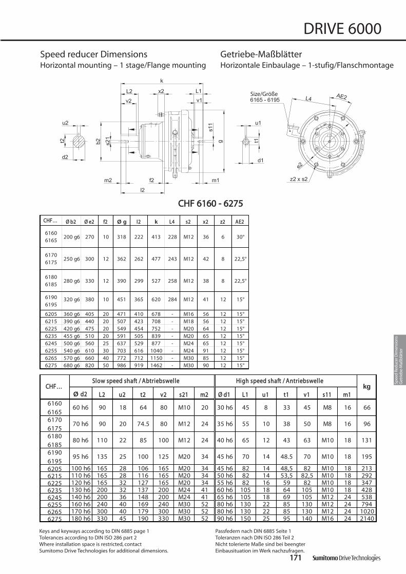
CCHHFF…… ØØ bb22 ØØ ee22 ff22 Ø g II22 k LL44 ss22 xx22 zz22 AAEE22
200 g6 270 10 318 222 413 228 M12 36 6 30°
250 g6 300 12 362 262 477 243 M12 42 8 22,5°
280 g6 330 12 390 299 527 258 M12 38 8 22,5°
320 g6 380 10 451 365 620 284 M12 41 12 15°
6205 360 g6 405 20 471 410 678 - M16 56 12 15°6215 390 g6 440 20 507 423 708 - M18 56 12 15°6225 420 g6 475 20 549 454 752 - M20 64 12 15°6235 455 g6 510 20 591 505 839 - M20 65 12 15°6245 500 g6 560 25 637 529 877 - M24 65 12 15°6255 540 g6 610 30 703 616 1040 - M24 91 12 15°6265 570 g6 660 40 772 712 1150 - M30 85 12 15°6275 680 g6 820 50 986 919 1462 - M30 90 12 15°
61806185
61906195
61706175
61606165
Ø dd22 LL22 uu22 tt22 vv22 ss2211 mm22 ØØ dd11 LL11 uu11 tt11 vv11 ss1111 mm11
60 h6 90 18 64 80 M10 20 30 h6 45 8 33 45 M8 16 66
70 h6 90 20 74.5 80 M12 24 35 h6 55 10 38 50 M8 16 96
80 h6 110 22 85 100 M12 24 40 h6 65 12 43 63 M10 18 131
95 h6 135 25 100 125 M20 34 45 h6 70 14 48.5 70 M10 18 195
6205 100 h6 165 28 106 165 M20 34 45 h6 82 14 48,5 82 M10 18 2136215 110 h6 165 28 116 165 M20 34 50 h6 82 14 53,5 82,5 M10 18 2926225 120 h6 165 32 127 165 M20 34 55 h6 82 16 59 82 M10 18 3476235 130 h6 200 32 137 200 M24 41 60 h6 105 18 64 105 M10 18 4286245 140 h6 200 36 148 200 M24 41 65 h6 105 18 69 105 M12 24 5386255 160 h6 240 40 169 240 M30 52 80 h6 130 22 85 130 M12 24 7946265 170 h6 300 40 179 300 M30 52 80 h6 130 22 85 130 M12 24 10206275 180 h6 330 45 190 330 M30 52 90 h6 150 25 95 140 M16 24 2140
kg
6180618561906195
61706175
61606165
CCHHFF……SSllooww ssppeeeedd sshhaafftt // AAbbttrriieebbsswweellllee HHiigghh ssppeeeedd sshhaafftt // AAnnttrriieebbsswweellllee
Size/Größe
CCHHFF 66116600 -- 66227755
117711
DRIVE 6000
Speed reducer Dimensions Getriebe-MaßblätterHorizontal mounting – 1 stage/Flange mounting Horizontale Einbaulage – 1-stufig/Flanschmontage
Keys and keyways according to DIN 6885 page 1Tolerances according to DIN ISO 286 part 2Where installation space is restricted, contact Sumitomo Drive Technologies for additional dimensions.
Passfedern nach DIN 6885 Seite 1Toleranzen nach DIN ISO 286 Teil 2Nicht tolerierte Maße sind bei beengter Einbausituation im Werk nachzufragen.
Spee
d Re
duce
r Dim
ensi
ons
Get
rieb
e-M
aßb
lätt
er

CCNNFFXX 66006600EE -- 66112255EE
117722
DRIVE 6000
Speed reducer Dimensions Getriebe-MaßblätterUniversal mounting – 1 stage/Flange mount Beliebige Einbaulage – 1-stufig/Flanschmontage
ØØ bb22 ØØ ee22 ff22 ØØ gg ll22 ss22 xx22 zz22 AAEE22 ØØ dd22 LL22 uu22 tt22 vv vv22 ss2211 mm22
80 g6 98 4 110 73 M6 21 6 0° 14 k6 30 5 16 2,5 25 M5 16
80 g6 98 4 110 84 M6 21 6 0° 20 k6 40 6 22,5 4 32 M6 16
95 g6 118 5 134 106 M8 27 8 22,5° 25 k6 50 8 28 3,5 40 M10 20
105 g6 134 6 150 129 M8 29 8 22,5° 25 k6 50 8 28 3,5 40 M10 20
105 g6 134 6 150 139 M8 28 8 22,5° 30 k6 60 8 34 3,5 50 M10 20
115 g6 146 6 162 143 M8 28 8 22,5° 35 k6 70 10 38 7 56 M12 20
140 g6 180 14 204 154 M10 30 6 0° 35 k6 70 10 38 7 56 M12 246120E6125E
6080E6085E
6090E6095E
6100E6105E
6110E6115E
HHiigghh ssppeeeedd sshhaafftt // AAnnttrriieebbsswweelllleeSSllooww ssppeeeedd sshhaafftt // AAbbttrriieebbsswweellllee
6070E6075E
6060E6065E
CCNNFFXX……

ØØ aa11 ØØ bb11 cc11 ØØ ee11 ff11 kk ØØ ss11 ØØ dd11 l1 LL11** uu11 tt11 kkgg
63/A140 140 95 H8 115 9 11 F7 7 23 4 Js9 12,871/C105 105 70 H8 85 4,5 154 6,671/C140 140 95 H8 115 9
63/A140 140 95 H8 115 9 11 F7 7 23 4 Js9 12,871/C 105 105 70 H8 11 85 4,5 6,671/C 140 140 95 H8 115 9
63/A140 140 95 H8 115 201 11 F7 6 23 4 Js9 12,871/A160 160 110 H8 130 206 14 F7 9 30 5 Js9 16,380/A200 19 F7 12 40 6 Js9 21,890/A200 24 F7 14 50 8 Js9 27,3
63/A140 140 95 H8 115 11 F7 6 23 4 Js9 12,871/A160 160 110 H8 130 14 F7 9 30 5 Js9 16,380/C120 120 80 H8 13 100 6,680/C160 160 110 H8 130 9 19 F7 12 40 6 Js9 21,8 1180/A200 200 130 H8 165 11 1290/C140 140 95 H8 13 11590/C160 160 110 H8 130 24 F7 14 50 8 Js9 27,390/A200 200 130 H8 165 11 12
71/A160 160 110 H8 11 130 241 9 14 F7 9 30 5 Js9 16,380/C120 120 80 H8 13 100 6,680/C160 160 110 H8 130 9 12 40 21,8 1380/A200 200 130 H8 165 11 1490/C140 140 95 H8 13 115 1290/C160 160 110 H8 130 24 F7 14 50 27,3 1390/A200 200 130 H8 165 11
100/112/C160 160 110 H8 14 130 5 277 9 28 F7 18 60 31,3
71/A160 160 110 H8 11 130 256 9 14 F7 9 30 5 Js9 16,3 1480/A200 19 F7 40 6 Js9 21,890/A200 24 F7 50 27,3
100/112/A250 250 180 H8 14 215 6 287 14 28 F7 18 60 31,3 16
80/A200 19 F7 12 40 6 Js9 21,890/A200 24 F7 14 50 27,3
100/112/C160 160 110 H8 130 9 25100/112/A250 250 180 H8 215 14 28
60606065
60806085
11
12
60706075
IInnppuutt eelleemmeennttAAnnttrriieebbsszzuubbeehhöörr
60906095
CCNNFFXX……
8 Js9
5 Js911
11
9
9
9
9
289
14 F7
165
4,5
4,5
165
267
217
243
61206125
61106115
11
12
13
200
200
61006105
12
12
130 H8
200
130 H8 278
279165
4,5
4.5
223
12
11
11
11
605
19 F7
28 F7
9
12
18
14 F7
31,3
5 Js9
6 Js9
24
12
12
158 Js9
8 Js9
14
L* = Length of motor shaftL* = Länge der Motorwelle
HHiigghh ssppeeeedd sshhaafftt ppoorrttiioonn // AAnnttrriieebbsssseeiittee
104,5
309
130 H8 12
16530
10
11
16,3
5
5
16,3
117733
DRIVE 6000
Speed reducer Dimensions Getriebe-MaßblätterUniversal mounting – 1 stage/Flange mounting Beliebige Einbaulage – 1-stufig/Flanschmontage
Keys and keyways according to DIN 6885 page 1Tolerances according to DIN ISO 286 part 2Where installation space is restricted, contact Sumitomo Drive Technologies for additional dimensions.
Passfedern nach DIN 6885 Seite 1Toleranzen nach DIN ISO 286 Teil 2Nicht tolerierte Maße sind bei beengter Einbausituation im Werk nachzufragen.
Spee
d Re
duce
r Dim
ensi
ons
Get
rieb
e-M
aßb
lätt
er

CCHHFFXX 66113300EE -- 66116655
117744
DRIVE 6000
Speed reducer Dimensions Getriebe-MaßblätterHorizontal mounting – 1 stage/Flange mount Horizontale Einbaulage – 1-stufig/Flanschmontage
ØØ bb22 ØØ ee22 ff22 ØØ gg ll22 LL44 ss22 xx22 zz22 AAEE22 ØØ dd22 LL22 uu22 tt22 vv vv22 ss2211 mm22
165 g6 205 16 230 208 208 M10 31 6 0° 50 k6 100 14 53.5 10 80 M16 30
165 g6 205 16 230 208 208 M10 31 6 0° 50 k6 100 14 53.5 10 80 M16 30
200 g6 270 10 300 222 228 M12 35 6 30° 60 h6 90 18 64 0 80 M10 2061606165
SSllooww ssppeeeedd sshhaafftt // AAbbttrriieebbsswweellllee
6140E6145E
6130E6135E
CCHHFFXX……
ØØ aa11 ØØ bb11 cc11 ØØ ee11 ff11 kk ØØ ss11 ØØ dd11 ll11 LL11** uu11 tt11
90/A200 200 130 H8 11 165 4,5 351 11 24 F7 14 50 8 Js9 27 40100/112/A250 250 180 H8 13 215 361 28 F7 18 60 8 Js9 31 42
132/A300 300 230 H8 17 265 387 38 F7 23 80 10 Js9 41 4790/A200 200 130 H8 11 165 4,5 351 11 24 F7 14 50 8 Js9 27 41
100/112/A250 250 180 H8 13 215 361 28 F7 18 60 8 Js9 31 43132/A300 300 230 H8 17 265 387 38 F7 23 80 10 Js9 41 48
100/112/A250 250 180 H8 14 215 394 28 F7 18 60 8 Js9 31 76132/A300 300 230 H8 16 265 416 38 F7 23 80 10 Js9 41 81160/A350 350 250 H8 16 300 6 452 18 42 F7 47 110 12 Js9 45 84
145
5 1461606165
L* = Length of motor shaft
L* = Länge der Motorwelle
HHiigghh ssppeeeedd sshhaafftt ppoorrttiioonn // AAnnttrriieebbsssseeiitteekkgg
IInnppuutt eelleemmeennttAAnnttrriieebbsszzuubbeehhöörr
61406145
61306135
CCHHFFXX……
145
Size/Größe6160, 6165
Size/Größe6130 - 6145

CCNNVV 66006600EE -- 66112255EE
117755
DRIVE 6000
Speed reducer Dimensions Getriebe-MaßblätterUniversal mounting – 1 stage/Flange mount Beliebige Einbaulage – 1-stufig/Flanschmontage
CCNNVV…… ØØ aa22 ØØ bb22 cc22 ØØ ee22 ff22 ØØ gg II22 kk ØØ ss22 zz22 AAEE22
120 80 j6 8 100 3 110 39 150 9 6 30°
160 110 j6 9 130 3 110 52 161 11 4 45°
160 110 j6 9 130 3 134 63 193 11 4 45°
160 110 j6 9 130 3 150 63 217 11 4 45°
160 110 j6 9 130 3 150 73 233 11 4 45°
200 130 j6 11 165 4 162 83 243 11 6 30°
200 130 j6 13 165 4 204 84 274 11 6 30°
6070E6075E
6060E6065E
6120E6125E
6080E6085E
6090E6095E
6100E6105E
6110E6115E
Keys and keyways according to DIN 6885 page 1Tolerances according to DIN ISO 286 part 2Where installation space is restricted, contact Sumitomo Drive Technologies for additional dimensions.
Passfedern nach DIN 6885 Seite 1Toleranzen nach DIN ISO 286 Teil 2Nicht tolerierte Maße sind bei beengter Einbausituation im Werk nachzufragen.
ØØ dd22 LL22 uu22 tt22 vv vv22 ss2211 mm22 ØØ dd11 LL11 uu11 tt11 vv11 ss1111 mm11
14 k6 30 5 16 2,5 25 M5 16 12 k6 25 4 13,5 22 M5 8 3,5
20 k6 40 6 23 4 32 M6 16 12 k6 25 4 13,5 22 M4 8 4,5
25 k6 50 8 28 3,5 40 M10 20 12 k6 25 4 13,5 22 M4 8 9,5
25 k6 50 8 27 3,5 40 M10 20 14 k6 25 5 16 21 M5 10 10
30 k6 60 8 33 3,5 50 M10 20 14 k6 25 5 16 21 M5 10 11
35 k6 70 10 38 7 56 M12 20 14 k6 25 5 16 21 M5 10 13
35 k6 70 10 38 7 56 M12 24 19 k6 25 5 21,5 27 M6 12 236120E6125E
6080E6085E
6090E6095E
6100E6105E
6110E6115E
kkggHHiigghh ssppeeeedd sshhaafftt // AAnnttrriieebbsswweellllee
6070E6075E
6060E6065E
SSllooww ssppeeeedd sshhaafftt // AAbbttrriieebbsswweelllleeCCNNVV……
Spee
d Re
duce
r Dim
ensi
ons
Get
rieb
e-M
aßb
lätt
er

CCHHVV 66113300EE -- 66114455EE
117766
DRIVE 6000
Speed reducer Dimensions Getriebe-MaßblätterHorizontal mounting – 1 stage/Flange mount Horizontale Einbaulage – 1-stufig/Flanschmontage
CCHHVV.... ØØaa22 ØØbb22 cc22 ØØee22 ff22 ØØgg ll22 LL44 kk ØØss22 zz22 AAEE22
260 200 f8 15 230 4 230 106 208 351 11 6 0°
260 200 f8 15 230 4 230 106 208 351 11 6 0°6140E6145E
6130E6135E
ØØdd22 LL22 uu22 tt22 vv vv22 ss2211 mm22 ØØdd11 LL11 uu11 tt11 vv11 ss1111 mm11
50 k6 100 14 53,5 10 80 M16 30 22 k6 40 6 24,5 34 M8 16 42
50 k6 100 14 53,5 10 80 M16 30 22 k6 40 6 24,5 34 M8 16 43
CCHHVV.... kkgg
6140E6145E
6130E6135E
SSllooww ssppeeeedd sshhaafftt // AAbbttrriieebbsswweellllee HHiigghh ssppeeeedd sshhaafftt // AAnnttrriieebbsswweellllee

Only size/nur Größe6165 - 6195
Only size/nur Größe6205 - 6275
CCHHVV 66116600 -- 66227755
117777
DRIVE 6000
Speed reducer Dimensions Getriebe-MaßblätterHorizontal mounting – 1 stage/Flange mount Horizontale Einbaulage – 1-stufig/Flanschmontage
Ø dd22 LL22 uu22 tt22 vv22 ss2211 mm22 ØØ dd11 LL11 uu11 tt11 vv11 ss1111 mm11
60 h6 90 18 64 80 M10 20 30 h6 45 8 33 45 M8 16 79
70 h6 90 20 74,5 80 M12 24 35 h6 55 10 38 50 M8 16 125
80 h6 110 22 85.0 100 M12 24 40 h6 65 12 43 63 M10 18 150
95 h6 135 25 100 125 M20 34 45 h6 70 14 48.5 70 M10 18 225
6205 100 h6 165 28 106 165 M20 34 45 h6 82 14 48,5 82 M10 18 2436215 110 h6 165 28 116 165 M20 34 50 h6 82 14 53,5 82,5 M10 18 3146225 120 h6 165 32 127 165 M20 34 55 h6 82 16 59 82 M10 18 3966235 130 h6 200 32 137 200 M24 41 60 h6 105 18 64 105 M10 18 4746245 140 h6 200 36 148 200 M24 41 65 h6 105 18 69 105 M12 24 5686255 160 h6 240 40 169 240 M30 52 80 h6 130 22 85 130 M12 24 8656265 170 h6 300 40 179 300 M30 52 80 h6 130 22 85 130 M12 24 11256275 180 h6 330 45 190 330 M30 52 90 h6 150 25 95 140 M16 24 2610
kkgg CCHHVV……SSllooww ssppeeeedd sshhaafftt // AAbbttrriieebbsswweellllee HHiigghh ssppeeeedd sshhaafftt // AAnnttrriieebbsswweellllee
61806185
61906195
61706175
61606165
Keys and keyways according to DIN 6885 page 1Tolerances according to DIN ISO 286 part 2Where installation space is restricted, contact Sumitomo Drive Technologies for additional dimensions.
Passfedern nach DIN 6885 Seite 1Toleranzen nach DIN ISO 286 Teil 2Nicht tolerierte Maße sind bei beengter Einbausituation im Werk nachzufragen.
CCHHVV…… ØØ aa22 ØØ bb22 cc22 ØØ ee22 ff22 ØØ gg ll22 LL44 kk ØØ ss22 zz22 AAEE22
340 270 f8 20 310 4 318 89 228 413 11 6 0°
400 316 f8 22 360 5 362 94 243 477 14 8 22,5°
430 345 f8 22 390 5 390 110 258 527 18 8 22,5°
490 400 f8 30 450 6 451 145 284 620 18 12 15°
6205 455 355 f8 30 405 5 471 204 - 678 22 8 0°6215 490 390 f8 35 440 7 507 203 - 708 24 8 0°6225 535 415 f8 35 475 10 549 210 - 752 27 8 0°6235 570 450 f8 40 510 10 591 250 - 839 27 8 0°6245 635 485 f8 40 560 10 637 250 - 877 33 8 0°6255 685 535 f8 45 610 10 703 295 - 1040 33 8 0°6265 750 570 f8 50 660 10 772 360 - 1150 39 8 0°6275 1160 900 f8 60 1020 10 986 355 - 1462 39 8 22,5°
61806185
61906195
61706175
61606165
Spee
d Re
duce
r Dim
ensi
ons
Get
rieb
e-M
aßb
lätt
er

CCNNVVXX 66006600EE -- 66112255EE
117788
DRIVE 6000
Speed reducer Dimensions Getriebe-MaßblätterUniversal mounting – 1 stage/Flange mount Beliebige Einbaulage – 1-stufig/Flanschmontage
ØØaa22 ØØbb22 cc22 ØØee22 ff22 ØØgg II22 ØØss22 zz22 AAEE22 ØØdd22 LL22 uu22 tt22 vv vv22 ss2211 mm22
120 80 j6 8 100 3 110 39 9 6 30° 14 k6 30 5 16 2,5 25 M5 16
160 110 j6 9 130 3 110 52 11 4 45° 20 k6 40 6 22,5 4,0 32 M6 16
160 110 j6 9 130 3 134 63 11 4 45° 25 k6 50 8 28 3,5 40 M10 20
160 110 j6 9 130 3 150 63 11 4 45° 25 k6 50 8 28 3,5 40 M10 20
160 110 j6 9 130 3 150 73 11 4 45° 30 k6 60 8 33 3,5 50 M10 20
200 130 j6 11 165 4 162 83 11 6 30° 35 k6 70 10 38 7,0 56 M12 20
200 130 j6 13 165 4 204 84 11 6 30° 35 k6 70 10 38 7,0 56 M12 24
6070E6075E
6060E6065E
6120E6125E
6080E6085E
6090E6095E
6100E6105E
6110E6115E
SSllooww ssppeeeedd sshhaafftt // AAbbttrriieebbsswweelllleeCCNNVVXX....
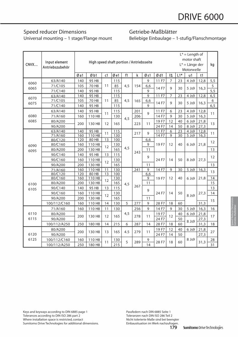
117799
DRIVE 6000
Speed reducer Dimensions Getriebe-MaßblätterUniversal mounting – 1 stage/Flange mount Beliebige Einbaulage – 1-stufig/Flanschmontage
ØØ aa11 ØØ bb11 cc11 ØØ ee11 ff11 kk ØØ ss11 ØØ dd11 l1 LL11** uu11 tt11
63/A140 140 95 H8 115 9 11 F7 7 23 4 Js9 12,8 5,571/C105 105 70 H8 85 4,5 154 6,6 571/C140 140 95 H8 115 9 5,563/A140 140 95 H8 115 9 11 F7 7 23 4 Js9 12,8 6,571/C105 105 70 H8 11 85 4,5 6,6 671/C140 140 95 H8 115 9 6,5
63/A140 140 95 H8 115 201 11 F7 6 23 4 Js9 12,871/A160 160 110 H8 130 206 14 F7 9 30 5 Js9 16,380/A200 19 F7 12 40 6 Js9 21,890/A200 24 F7 14 50 8 Js9 27,363/A140 140 95 H8 115 11 F7 6 23 4 Js9 12,871/A160 160 110 H8 130 14 F7 9 30 5 Js9 16,380/C120 120 80 H8 13 100 6,680/C160 160 110 H8 130 9 19 F7 12 40 6 Js9 21,880/A200 200 130 H8 165 11 1390/C140 140 95 H8 13 11590/C160 160 110 H8 130 24 F7 14 50 8 Js9 27,390/A200 200 130 H8 165 11 1371/A160 160 110 H8 11 130 241 9 14 F7 9 30 5 Js9 16,380/C120 120 80 H8 13 100 6,680/C160 160 110 H8 130 9 12 40 21,8 1480/A200 200 130 H8 165 11 1590/C140 140 95 H8 13 115 1390/C160 160 110 H8 130 24 F7 14 50 27,3 1490/A200 200 130 H8 165 11
100/112/C160 160 110 H8 14 130 5 277 9 28 F7 18 60 31,3
71/A160 160 110 H8 11 130 256 9 14 F7 9 30 5 Js9 16,3 1680/A200 19 F7 40 6 Js9 21,890/A200 24 F7 50 27,3
100/112/A250 250 180 H8 14 215 6 287 14 28 F7 18 60 31,3 18
80/A200 19 F7 12 40 6 Js9 21,890/A200 24 F7 14 50 27,3
100/112/C160 160 110 H8 130 9 28100/112/A250 250 180 H8 215 14 31
11
12
12
15
60606065
CCNNVVXX……
60806085
60906095
61006105
267
60706075
9
165
217
243
4,5
4,5
12
kkggIInnppuutt eelleemmeenntt
AAnnttrriieebbsszzuubbeehhöörr
5 Js9 16,314 F7 9
11
4,5
4,5
4.5
5
165
165
12
12
130 H8
130 H8
30
200 130 H8 12
165
223
14 F7
278
61206125
61106115
11
11
11
12
12
13
200
200 279
289
11
9
9
9
11
11
60
30
19 F7
28 F7
9
12
18 31,3
5 Js9
6 Js9
8 Js9
27
L* = Length of motor shaft
L* = Länge der Motorwelle
HHiigghh ssppeeeedd sshhaafftt ppoorrttiioonn // AAnnttrriieebbsssseeiittee
11
13
13
178 Js9
8 Js9
16,3
Keys and keyways according to DIN 6885 page 1Tolerances according to DIN ISO 286 part 2Where installation space is restricted, contact Sumitomo Drive Technologies for additional dimensions.
Passfedern nach DIN 6885 Seite 1Toleranzen nach DIN ISO 286 Teil 2Nicht tolerierte Maße sind bei beengter Einbausituation im Werk nachzufragen.
Spee
d Re
duce
r Dim
ensi
ons
Get
rieb
e-M
aßb
lätt
er

Size/Größe
Size/Größe
CCHHVVXX 66113300EE -- 66116655
118800
DRIVE 6000
Speed reducer Dimensions Getriebe-MaßblätterHorizontal mounting – 1 stage/Flange mount Horizontale Einbaulage – 1-stufig/Flanschmontage
ØØ aa22 ØØ bb22 cc22 ØØ ee22 f2 ØØ gg ll22 LL44 ØØ ss22 z2 AAEE22 ØØ dd22 LL22 uu22 tt22 vv vv22 ss2211 mm22
260 200 f8 15 230 4 230 106 208 11 6 0° 50 k6 100 14 53.5 10 80 M16 30
260 200 f8 15 230 4 230 106 208 11 6 0° 50 k6 100 14 53.5 10 80 M16 30
340 270 f8 20 310 4 300 89 228 11 6 0° 60 h6 90 18 64 0 80 M10 20
SSllooww ssppeeeedd sshhaafftt // AAbbttrriieebbsswweellllee
61606165
6140E6145E
6130E6135E
CCHHVVXX……
Ø a1 Ø b1 c1 Ø e1 f1 k Ø s1 Ø d1 l1 L1* u1 t1
90/A200 200 130 H8 11 165 4,5 351 11 24 F7 14 50 8 Js9 27,3 45100/112/A250 250 180 H8 13 215 361 28 F7 18 60 8 Js9 31,3 47
132/A300 300 230 H8 17 265 387 38 F7 23 80 10 Js9 41,3 52
90/A200 200 130 H8 11 165 4,5 351 11 24 F7 14 50 8 Js9 27,3 46100/112/A250 250 180 H8 13 215 361 28 F7 18 60 8 Js9 31,3 48
132/A300 300 230 H8 17 265 387 38 F7 23 80 10 Js9 41,3 53
100/112/A250 250 180 H8 14 215 394 28 F7 18 60 8 Js9 31,3 85132/A300 300 230 H8 265 416 38 F7 23 80 10 Js9 41,3 90160/A350 350 250 H8 300 6 452 18 42 F7 47 110 12 Js9 45,3 95
kkgg
L* = Length of motor shaft
L* = Länge der Motorwelle
61606165
HHiigghh ssppeeeedd sshhaafftt ppoorrttiioonn // AAnnttrriieebbsssseeiitteeIInnppuutt eelleemmeennttAAnnttrriieebbsszzuubbeehhöörr
61406145
61306135
CCHHHHXX……
145
14
165 14
5

CCVV VV 66113300EE -- 66114455EE
118811
DRIVE 6000
Speed reducer Dimensions Getriebe-MaßblätterVertical mounting – 1 stage/Flange mount Vertikale Einbaulage – 1-stufig/Flanschmontage
CCVVVV…… ØØ aa22 ØØ bb22 cc22 ØØ ee22 f2 ØØ gg ll22 kk rr11 rr22 ØØ ss22 z2 AAEE22
260 200 f8 15 230 4 230 106 351 163 225 11 6 0°
260 200 f8 15 230 4 230 106 351 163 225 11 6 0°6140E6145E
6130E6135E
Keys and keyways according to DIN 6885 page 1Tolerances according to DIN ISO 286 part 2Where installation space is restricted, contact Sumitomo Drive Technologies for additional dimensions.
Passfedern nach DIN 6885 Seite 1Toleranzen nach DIN ISO 286 Teil 2Nicht tolerierte Maße sind bei beengter Einbausituation im Werk nachzufragen.
ØØ dd22 LL22 uu22 tt22 vv vv22 ss2211 mm22 ØØ dd11 LL11 uu11 tt11 vv11 ss1111 mm11
50 k6 91 14 53,5 10 80 M16 30 22 k6 40 6 24,5 34 M8 16 42
50 k6 91 14 53,5 10 80 M16 30 22 k6 40 6 24,5 34 M8 16 43
CCVVVV…… kkggSSllooww ssppeeeedd sshhaafftt // AAbbttrriieebbsswweellllee HHiigghh ssppeeeedd sshhaafftt // AAnnttrriieebbsswweellllee
6140E6145E
6130E6135E
Spee
d Re
duce
r Dim
ensi
ons
Get
rieb
e-M
aßb
lätt
er

* Lubrication fittings may have different positions dependent on frame size.
Die Schmierarmaturen sind, je nach Getriebegröße, an verschiedenen Positionen. Bei Fettschmierung (untersetzungsabhängig) entfallen die Schmierarmaturen.
** Frame size 6190/6195 may use 2 pumps dependent on ratio.
Bei Größe 6190DA-6195DB sind, je nach Untersetzung, auch 2 Pumpen möglich.
CCVV VV 66116600 -- 66119955
118822
DRIVE 6000
Speed reducer Dimensions Getriebe-MaßblätterVertical mounting – 1 stage/Flange mount Vertikale Einbaulage – 1-stufig/Flanschmontage
CCVVVV…… ØØ aa22 ØØ bb22 cc22 ØØ ee22 ff22 ØØ gg ll22 kk rr11 rr22 ØØ ss22 zz22 AAEE22
340 270 f8 20 310 4 318 89 413 221 200 11 6 0°
400 316 f8 22 360 5 362 94 477 232 225 14 8 22,5°
430 345 f8 22 390 5 390 110 527 237 240 18 8 22,5°
490 400 f8 30 450 6 451 145 620 269 270 18 12 15°
61806185
61906195
61706175
61606165
Ø dd22 LL22 uu22 tt22 vv22 ss2211 mm22 ØØ dd11 LL11 uu11 tt11 vv11 ss1111 mm11
60 h6 80 18 64 80 M10 20 30 h6 45 8 33 45 M8 16 79
70 h6 84 20 74,5 80 M12 24 35 h6 55 10 38 50 M8 16 125
80 h6 100 22 85 100 M12 24 40 h6 65 12 43 63 M10 18 150
95 h6 125 25 100 125 M20 34 45 h6 70 14 48.5 70 M10 18 225
61806185
61906195
61706175
61606165
kkgg CCVVVV……SSllooww ssppeeeedd sshhaafftt // AAbbttrriieebbsswweellllee HHiigghh ssppeeeedd sshhaafftt // AAnnttrriieebbsswweellllee

118833
DRIVE 6000
Speed reducer Dimensions Getriebe-MaßblätterVertical mounting – 1 stage/Flange mount Vertikale Einbaulage – 1-stufig/Flanschmontage
CCVVVV…… ØØ aa22 ØØ bb22 cc22 ØØ ee22 ff22 ØØ gg ll22 kk rr11 rr22 ØØ ss22 zz22 AAEE22
6205 455 355 f8 30 405 5 471 204 678 341 287 22 8 0°6215 490 390 f8 35 440 7 507 203 708 357 306 24 8 0°6225 535 415 f8 35 475 10 549 210 752 352 326 27 8 0°6235 570 450 f8 40 510 10 591 250 839 359 344 27 8 0°6245 635 485 f8 40 560 10 637 250 877 370 371 33 8 0°6255 685 535 f8 45 610 10 703 295 1040 426 399 33 8 0°6265 750 570 f8 50 660 10 772 360 1150 460 431 39 8 0°6275 1160 900 f8 60 1020 10 986 355 1462 610 613 39 8 22,5°
Ø dd22 LL22 uu22 tt22 vv22 ss2211 mm22 ØØ dd11 LL11 uu11 tt11 vv11 ss1111 mm11
6205 100 h6 165 28 106 165 M20 34 45 h6 82 14 48.5 82 M10 18 2436215 110 h6 165 28 116 165 M20 34 50 h6 82 14 53.5 82,5 M10 18 3146225 120 h6 165 32 127 165 M20 34 55 h6 82 16 59 82 M10 18 3966235 130 h6 200 32 137 200 M24 41 60 h6 105 18 64 105 M10 18 4746245 140 h6 200 36 148 200 M24 41 65 h6 105 18 69 105 M12 24 5686255 160 h6 240 40 169 240 M30 52 80 h6 130 22 85 130 M12 24 8656265 170 h6 300 40 179 300 M30 52 80 h6 130 22 85 130 M12 24 11256275 180 h6 320 45 190 320 M30 52 90 h6 150 25 95 140 M16 24 2610
kkgg CCVVVV……SSllooww ssppeeeedd sshhaafftt // AAbbttrriieebbsswweellllee HHiigghh ssppeeeedd sshhaafftt // AAnnttrriieebbsswweellllee
* Lubrication fittings may have different positions dependent on frame size.
Die Schmierarmaturen sind, je nach Getriebegröße, an verschiedenen Positionen. Bei Fettschmierung (untersetzungsabhängig) entfallen die Schmierarmaturen.
** Frame size 6225, 6235 and 6245 may use 2 pumps dependent on ratio. Bei den Größen 6225, 6235 und 6245 sind, je nach Untersetzung, auch 2 Pumpen möglich. Bei der Größe 6275 wird eine externe Pumpe eingesetzt.
view rotatedgedreht gezeichnet
CCVV VV 66220055-- 66227755
Keys and keyways according to DIN 6885 page 1Tolerances according to DIN ISO 286 part 2Where installation space is restricted, contact Sumitomo Drive Technologies for additional dimensions.
Passfedern nach DIN 6885 Seite 1Toleranzen nach DIN ISO 286 Teil 2Nicht tolerierte Maße sind bei beengter Einbausituation im Werk nachzufragen.
Spee
d Re
duce
r Dim
ensi
ons
Get
rieb
e-M
aßb
lätt
er

CCVV VVXX 66113300EE -- 66116655
118844
DRIVE 6000
Speed reducer Dimensions Getriebe-MaßblätterVertical mounting – 1 stage/Flange mount Vertikale Einbaulage – 1-stufig/Flanschmontage
ØØ aa22 ØØ bb22 cc22 ØØ ee22 ff22 ØØ gg ll22 rr11 rr22 ØØ ss22 zz22 AAEE22 ØØ dd22 LL22 uu22 tt22 vv vv22 ss2211 mm22
260 200 f8 15 230 4 230 106 169 225 11 6 0° 50 k6 91 14 53,5 10 80 M16 30
260 200 f8 15 230 4 230 106 169 225 11 6 0° 50 k6 91 14 53,5 10 80 M16 30
340 270 f8 20 310 4 300 89 224 200 11 6 0° 60 h6 80 18 64 0 80 M10 20
SSllooww ssppeeeedd sshhaafftt // AAbbttrriieebbsswweellllee
61606165
6140E6145E
6130E6135E
CCVVVVXX……
ØØ aa11 ØØ bb11 cc11 ØØ ee11 ff11 kk ØØ ss11 ØØ dd11 l1 LL11** uu11 tt11
90/A200 200 130 H8 11 165 4,5 351 11 24 F7 14 50 8 Js9 27,3 45
100/112/A250 250 180 H8 13 215 361 28 F7 18 60 8 Js9 31,3 47132/A300 300 230 H8 17 265 387 38 F7 23 80 10 Js9 41,3 52
90/A200 200 130 H8 11 165 4,5 351 11 24 F7 14 50 8 Js9 27,3 46100/112/A250 250 180 H8 13 215 361 28 F7 18 60 8 Js9 31,3 48
132/A300 300 230 H8 17 265 387 38 F7 23 80 10 Js9 41,3 53
100/112/A250 250 180 H8 14 215 394 28 F7 18 60 8 Js9 31,3 85132/A300 300 230 H8 265 416 38 F7 23 80 10 Js9 41,3 90160/A350 350 250 H8 300 6 452 18 42 F7 47 109 12 Js9 45,3 95
16
145
5 14
kkgg
L* = Length of motor shaft
L* = Länge der Motorwelle
61606165
HHiigghh ssppeeeedd sshhaafftt ppoorrttiioonn // AAnnttrriieebbsssseeiitteeIInnppuutt eelleemmeennttAAnnttrriieebbsszzuubbeehhöörr
61406145
61306135
CCVVVVXX……
5 14

6060E - 6145E 6160 - 6275
d1
e1
AE1
z1 x s1
l1
i1
f1
l1
i1
f1
d1
L1b1 a1
L3
L2b1 a1
66006600EE -- 66222255
118855
DRIVE 6000
Speed reducer Dimensions Getriebe-MaßblätterInput side Antriebsseite
SSiizzeeGGrröößßee
ØØ aa11 ØØ bb11 ØØ dd11 ØØ ee11 ff11 ii11 ll11 ØØ ss11 zz11 AAEE22
6 0 °2 71 40 11226 146 js7 22 k6 205
40 11 6 0 °22 k6 205 2 71
145 js7200
226 146 js7
62218019 k6 0 °61135
25 M10 4 45 °14 k6 146 3 32
25 9 8 22,5 °14 k6 134 2 46
54214 k6 134
25
22,5 °8925
0 °
134 95 js7 12 k6 118 2 32 M10 45 °4
2 48 25 7
6 0 °
110
2 48 25 7
685 js7 12 k6
6130E6135E6140E6145E
110 85 js7
105 js7150
150 105 js7
162 120 js7
6120E6125E
6080E6085E6090E6095E6100E6105E6110E6115E
6070E6075E
6060E6065E
12 k6 98
98
Keys and keyways according to DIN 6885 page 1Tolerances according to DIN ISO 286 part 2Where installation space is restricted, contact Sumitomo Drive Technologies for additional dimensions.
Passfedern nach DIN 6885 Seite 1Toleranzen nach DIN ISO 286 Teil 2Nicht tolerierte Maße sind bei beengter Einbausituation im Werk nachzufragen.
SSiizzeeGGrröößßee
ØØ aa11 ØØ bb11 ØØ dd11 ØØ ee11 ff11 ii11 ll11 LL11 LL22 LL33
6205 443 342 js7 45 h6 405 4 149 82 473 320 566215 480 380 js7 50 h6 440 4 154 82.5 509 350 646225 521 420 js7 55 h6 475 4 157 82 551 380 696235 557 457 js7 60 h6 510 4 183 105 593 420 696245 610 500 js7 65 h6 560 4 191 105 639 440 826255 666 550 js7 80 h6 610 4 233 130 705 510 916265 730 548 js7 80 h6 660 4 229 130 771 540 1016275 940 760 js7 90 h6 820 5 273 150 987 690 103
454 320 46
393 280 46
420 340 js7 45 h6 380 4 137 70
330 4 120 65
55 363 240 4535 h6 300 4 111
45 318 230 4030 h6 270 4 91
61706175
61606165
295 230 js7
330 255 js7
61806185
61906195
360 295 js7 40 h6
Spee
d Re
duce
r Dim
ensi
ons
Get
rieb
e-M
aßb
lätt
er

6060E - 6145E 6160 - 6165
a1b1
L1
i1k
e1
z1 x s1
q1a1b1q1
f1
c1
L1
i1k
f1
c1
66006600EE -- 66116655
118866
DRIVE 6000
Speed reducer Dimensions Getriebe-MaßblätterMotor adaptor Motor Adaptor
ØØ aa11 ØØ bb11 cc11 ØØ ee11 ff11 ii11 LL11 ss11 zz11 ØØ qq116060E6065E6070E6075E
6080E 71/A160 160 110 h8 10 130 4,5 33 9 656085E 80/A200 200 130 H8 12 165 5 43 11 90
71/A160 160 110 h8 10 130 33 980/A200 4390/A200 53 100
71/A160 160 110 h8 10 130 4 33 M86100E 80/A200 10 10 43 906105E 90/A200 12 5 51
100/112/A250 250 180 h8 16 215 6 63 14 120
71/A160 160 110 h8 10 130 33 96110E 80/A200 906115E 90/A200
100/112/A250 250 180 h8 15 215 6 63 14 100
71/A160 110 h8 10 130 10 33 M8 1006120E 80/A2006125E 90/A200
100/112/A250 250 180 h8 15 215 6 63 14 150
80/A2006130E 90/A2006135E 100/112/A250 250 180 h8 215 63 150
132/A300 300 230 H8 265 83 190
80/A2006140E 90/A2006145E 100/112/A250 250 180 h8 215 63 150
132/A300 300 230 H8 265 83 190
100/112/A250 250 180 h8 215 63 160132/A300 300 230 H8 265 83 190160/A350 350 250 H8 20 300 7 113 18 180
645
144
120
15 6 14
165 12 5340
124
6
53
200
130 H8
15
5 53
11
110
220 12 165 12 120
11 425
IInnppuutt eelleemmeennttAAnnttrriieebbsszzuubbeehhöörr
25 4
6090E6095E 200 130 H8 12 165
5 25
4 654,5 35 25
SSiizzeeGGrröößßee
4
HHiigghh ssppeeeedd sshhaafftt ppoorrttiioonn // AAnnttrriieebbsssseeiittee
71/A160 160 110 H8 11 130
90
9
11 45
53 25
200 130 H8
200 130 H8 12 165
165
130 H8 12 165
61606165
220 130 H8 12
15
1135 4
4012
144

DRIVE 6000
a1b1
c1
L1
f1
i1k
e1
z1 x s1
q1
66117700-- 66226655
118877
Speed reducer Dimensions Getriebe-MaßblätterMotor adaptor Motor Adaptor
ØØ aa11 ØØ bb11 cc11 ØØ ee11 ff11 ii11 LL11 ss11 zz11 ØØ qq11100/112/A250 250 180 h8 15 215 6 63 150
6170 132/A300 300 230 H8 15 265 6 83 1906175 160/A350
180/A350
100/112/A250 250 180 h8 15 215 6 63 14 160132/A300 300 230 H8 15 265 83 15 190160/A350180/A350 200200/A400 400 300 H8 19 350 114 220132/A300 300 230 H8 16 265 6 83 M12160/A350180/A350200/A400 400 300 H8 350 114 220225/A450 450 350 H8 400 144 8 270
160/A350180/A350 18200/A400 400 300 H8 350 114 220225/A450 450 350 H8 19 400 144 8 270
160/A350180/A350200/A400 400 300 H8 350 114 210225/A450 450 350 H8 400 270250/A550 550 450 H8 22 500 290
180/A350 350 250 H8 300 200200/A400 400 300 H8 350 210225/A450 450 350 H8 400 270250/A550 550 450 H8 500 290
200/A400 400 300 H8 20 350 114 4 260225/A450 450 350 H8 400 270250/A550280/A550
200/A400 400 300 H8 20 350 114 4225/A450 450 350 H8 400250/A550280/A550
225/A450 450 350 H8 400 19 280250/A550280/A550
250/A550280/A550
7 144 130
8
114
144
188
824
1134
6265 550 450 H8 22 19 8500
622518
22
20020
237
144
82 18
7
350 250 H8 300
6215
190
6205350 250 H8 300 113
20 4200
250 H8
65113350 250 H8
113
61806185 300 720
6255
6235550
6245550
350
144
300
260105
130 818
350
350
14
22450 H8
7
144
500
18
105 18
7
18
SSiizzeeGGrröößßee
4350 250 H8 20 300
HHiigghh ssppeeeedd sshhaafftt ppoorrttiioonn // AAnnttrriieebbsssseeiittee
55
IInnppuutt eelleemmeennttAAnnttrriieebbsszzuubbeehhöörr
61906195
70300
20 7113
500
7
4
200
8
8
82
18
18
4
7 144
350
7
22550 450 H8 500
450 H822
Keys and keyways according to DIN 6885 page 1Tolerances according to DIN ISO 286 part 2Where installation space is restricted, contact Sumitomo Drive Technologies for additional dimensions.
Passfedern nach DIN 6885 Seite 1Toleranzen nach DIN ISO 286 Teil 2Nicht tolerierte Maße sind bei beengter Einbausituation im Werk nachzufragen.
Spee
d Re
duce
r Dim
ensi
ons
Get
rieb
e-M
aßb
lätt
er

118888
DRIVE 6000
CCNNHH 66006600DDAAEE -- 66112255DDBBEE
Speed reducer Dimensions Getriebe-MaßblätterHorizontal mounting - 2 stage/Foot mount Horizontale Einbaulage – 2-stufig/Fußmontage
Ød2 L2 u2 t2 v v2 s21 m2 Ød1 L1 u1 t1 v1 s11 m1
14 k6 30 5 16 2,5 25 M5 16 12 k6 25 4 13,5 22 M 4 8 4
20 k6 40 6 22,5 4 32 M6 16 12 k6 25 4 13,5 22 M 4 8 5
25 k6 50 8 28 3,5 40 M10 20 12 k6 25 4 13,5 22 M 4 8 12
30 k6 60 8 33 3,5 50 M10 20 12 k6 25 4 13,5 22 M 4 8 15
35 k6 70 10 38 3,5 56 M12 24 12 k6 25 4 13,5 22 M 4 8 26
35 k6 70 10 38 7 56 M12 24 14 k6 25 5 16 21 M 5 10 30
CCNNHH....
6120DAE6125DAE
6120DBE6125DBE
kkgg
6070DAE6075DAE
6090DAE6095DAE
6100DAE6105DAE
6060DAE6065DAE
SSllooww ssppeeeedd sshhaafftt // AAbbttrriieebbsswweellllee HHiigghh ssppeeeedd sshhaafftt // AAnnttrriieebbsswweellllee
CCNNHH…… aa bb cc e ee33 f ØØ gg hh HH kk nn ØØ ss
60 120 10 84 12 144 110 80 178 48 9
60 120 10 84 12 144 110 80 194 48 9
90 150 12 135 15 180 150 100 258 65 11
90 150 12 135 15 180 150 100 283 40 11
115 190 15 155 20 230 204 120 257 308 55 14
115 190 15 155 20 230 204 120 257 327 55 14
6060DAE6065DAE
6120DBE6125DBE
6090DAE6095DAE
6100DAE6105DAE
6120DAE6125DAE
6070DAE6075DAE

118899
DRIVE 6000
Speed reducer Dimensions Getriebe-MaßblätterHorizontal mounting – 2 stage/Foot mount Horizontale Einbaulage – 2-stufig/Fußmontage
Ød2 L2 u2 t2 v v2 s21 m2 Ød1 L1 u1 t1 v1 s11 m1
50 k6 100 14 53,5 10 80 M16 30 14 k6 25 5 16 21 M 5 10 45
50 k6 100 14 53,5 10 80 M16 30 14 k6 25 5 16 21 M 5 10 46
50 k6 100 14 53,5 10 80 M16 30 14 k6 25 5 16 21 M 5 10 46
60 h6 90 18 64 0 80 M10 20 14 k6 25 5 16 21 M 5 10 87
CCHHHH....SSllooww ssppeeeedd sshhaafftt // AAbbttrriieebbsswweellllee HHiigghh ssppeeeedd sshhaafftt // AAnnttrriieebbsswweellllee
kkgg
6130DBE6135DBE
6130DCE6135DCE
6140DCE6145DCE
6160DB6165DB
CCHHHH.... aa bb cc e ee33 f ØØgg hh HH kk nn ØØss ww
145 290 22 195 25 330 230 150 394 65 18 130
145 290 22 195 25 330 230 150 400 65 18 130
145 290 22 195 25 330 230 150 400 65 18 130
150 370 25 238 44 410 300 160 353 440 75 18 139
6130DCE6135DCE
6140DCE6145DCE
6160DB6165DB
6130DBE6135DBE
Keys and keyways according to DIN 6885 page 1Tolerances according to DIN ISO 286 part 2Where installation space is restricted, contact Sumitomo Drive Technologies for additional dimensions.
Passfedern nach DIN 6885 Seite 1Toleranzen nach DIN ISO 286 Teil 2Nicht tolerierte Maße sind bei beengter Einbausituation im Werk nachzufragen.
Only size/nur Größe6160DB, 6165DB
CCHHHH 66113300DDBBEE -- 66116655DDBB
Spee
d Re
duce
r Dim
ensi
ons
Get
rieb
e-M
aßb
lätt
er

CCHHHH 66116600DDCC -- 66119955DDBB
119900
DRIVE 6000
Speed reducer Dimensions Getriebe-MaßblätterHorizontal mounting – 2 stage/Foot mount Horizontale Einbaulage – 2-stufig/Fußmontage
CCHHHH…… aa bb cc ee ee33 ff ØØ gg hh HH kk nn ØØ ss ww
150 370 25 238 44 410 300 160 353 463 75 18 139
275 380 30 335 30 430 340 200 418 510 80 22 125
320 420 30 380 30 470 370 220 451 577 85 22 145
380 480 35 440 30 530 430 250 531 629 90 26 170
380 480 35 440 30 530 430 250 531 653 90 26 1706190DB6195DB
6180DB6185DB
6190DA6195DA
6170DC6175DC
6160DC6165DC
Ødd22 LL22 uu22 tt22 vv22 ss2211 mm22 ØØdd11 LL11 uu11 tt11 vv11 ss1111 mm11
60 h6 90 18 64 80 M10 20 19 k6 35 6 21,5 27 M6 12 94
70 h6 90 20 74.5 80 M12 24 19 k6 35 6 21,5 27 M6 12 128
80 h6 110 22 85 100 M12 24 22 k6 40 6 24,5 34 M8 16 183
95 h6 135 25 100 125 M20 34 19 k6 35 6 21,5 27 M6 12 241
95 h6 135 25 100 125 M20 34 22 k6 40 6 24,5 34 M8 16 250
kkgg
6190DB6195DB
SSllooww ssppeeeedd sshhaafftt // AAbbttrriieebbsswweellllee HHiigghh ssppeeeedd sshhaafftt // AAnnttrriieebbsswweellllee
6180DB6185DB
6190DA6195DA
6170DC6175DC
6160DC6165DC
CCHHHH....

119911
DRIVE 6000
Speed reducer Dimensions Getriebe-MaßblätterHorizontal mounting – 2 stage/Foot mount Horizontale Einbaulage – 2-stufig/Fußmontage
CCHHHH…… aa bb cc ee ee33 ff ØØ gg hh HH kk nn ØØ ss ww
6205DB 360 440 35 440 40 530 448 250 530 705 100 26 2156215DA 395 480 40 475 40 580 485 265 575 731 110 26 2106225DA 420 540 40 520 50 620 526 280 610 773 115 33 2306225DB 420 540 40 520 50 620 526 280 610 860 115 33 2306235DA 460 580 45 560 50 670 562 300 667 883 120 33 2606245DA 480 630 45 580 50 720 614 335 729 921 128 39 2636255DA 520 670 50 630 55 780 670 375 815 1081 140 39 3206265DA 590 770 55 700 55 880 736 400 874 1243 160 45 3906275DA 420 1050 60 1040 100 1160 950 540 1161 1505 200 45 485
Ødd22 LL22 uu22 tt22 vv22 ss2211 mm22 ØØdd11 LL11 uu11 tt11 vv11 ss1111 mm116205DB 100 h6 165 28 106 165 M20 34 22 k6 40 6 24,5 34 M8 16 2736215DA 110 h6 165 28 116 165 M20 34 22 k6 40 6 24,5 34 M8 16 3546225DA 120 h6 165 32 127 165 M20 34 22 k6 40 6 24,5 34 M8 16 4296225DB 120 h6 165 32 127 165 M20 34 35 h6 55 10 38 50 M8 16 4766235DA 130 h6 200 32 137 200 M24 41 30 h6 45 8 33 45 M8 16 5486245DA 140 h6 200 36 148 200 M24 41 30 h6 45 8 33 45 M8 16 6566255DA 160 h6 240 40 169 240 M30 52 35 h6 55 10 38 50 M8 16 10106265DA 170 h6 300 40 179 300 M30 52 45 h6 70 14 48,5 70 M10 18 13406275DA 180 h6 330 45 190 330 M30 52 45 h6 70 14 48,5 70 M10 18 2480
CCHHHH....SSllooww ssppeeeedd sshhaafftt // AAbbttrriieebbsswweellllee HHiigghh ssppeeeedd sshhaafftt // AAnnttrriieebbsswweellllee
kkgg
Only size/nur Größe 6275
CCHHHH 66220055DDBB -- 66227755DDAA
Keys and keyways according to DIN 6885 page 1Tolerances according to DIN ISO 286 part 2Where installation space is restricted, contact Sumitomo Drive Technologies for additional dimensions.
Passfedern nach DIN 6885 Seite 1Toleranzen nach DIN ISO 286 Teil 2Nicht tolerierte Maße sind bei beengter Einbausituation im Werk nachzufragen.
Spee
d Re
duce
r Dim
ensi
ons
Get
rieb
e-M
aßb
lätt
er

CCNNHHXX 66006600DDAAEE -- 66112255DDBBEE
119922
DRIVE 6000
Speed reducer Dimensions Getriebe-MaßblätterUniversal mounting – 2 stage/Foot mount Beliebige Einbaulage – 2-stufig/Fußmontage
aa bb cc ee ee33 ff ØØ gg hh HH nn ØØ ss ww ØØ dd22 LL22 uu22 tt22 vv vv22 ss2211 mm22
60 120 10 84 12 144 110 80 - 48 9 46 14 k6 30 5 16 2,5 25 M 5 16
60 120 10 84 12 144 110 80 - 48 9 57 20 k6 40 6 23 4 32 M 6 16
90 150 12 135 15 180 150 100 - 65 11 75 25 k6 50 8 28 3,5 40 M 10 20
90 150 12 135 15 180 150 100 - 40 11 85 30 k6 60 8 33 3,5 50 M 10 20
112 190 15 155 20 230 204 120 - 55 14 97 35 k6 70 10 38 7 56 M 12 24
115 190 15 155 20 230 204 120 157 55 14 97 35 k6 70 10 38 7 56 M 12 24
6060DAE6065DAE
SSllooww ssppeeeedd sshhaafftt // AAbbttrriieebbsswweelllleeCCNNHHXX……
6120DBE6125DBE
6070DAE6075DAE
6090DAE6095DAE
6100DAE6105DAE
6120DAE6125DAE

119933
DRIVE 6000
Speed reducer Dimensions Getriebe-MaßblätterUniversal mounting – 2 stage/Foot mount Beliebige Einbaulage – 2-stufig/Fußmontage
ØØ aa11 ØØ bb11 cc11 ØØ ee11 ff11 kk ØØ ss11 ØØ dd11 ll11 LL11** uu11 tt11
63/A 140 140 95 H8 115 9 11 F7 7 23 4 Js9 12,871/C 105 105 70 H8 11 85 4,5 188 6,671/C 140 140 95 H8 115 9
63/A 140 140 95 H8 115 9 11 F7 7 23 4 Js9 12,8 771/C 105 105 70 H8 11 85 4,5 6,6 671/C 140 140 95 H8 115 9 7
63/A 140 140 95 H8 115 9 11 F7 7 23 4 Js9 12,871/C 105 105 70 H8 11 85 4,5 263 6,6 1471/C 140 140 95 H8 115 9
63/A 140 140 95 H8 115 9 11 F7 7 23 4 Js9 12,871/C 105 105 70 H8 11 85 4,5 287 6,6 1771/C 140 140 95 H8 115 963/A 140 140 95 H8 115 9 11 F7 7 23 4 Js9 12,871/C 105 105 70 H8 11 85 4,5 313 6,6 9 2871/C 140 140 95 H8 115 9 9
63/A 140 140 95 H8 115 11 F7 6 23 4 Js9 12,871/A 160 160 110 H8 130 14 F7 9 30 5 Js9 16,3 3280/C 120 120 80 H8 13 100 6,680/C 160 160 110 H8 130 9 12 40 6 Js9 21,8 3380/A 200 200 130 H8 165 11 3490/C 140 140 95 H8 13 115 3290/C 160 160 110 H8 130 24 F7 14 50 8 Js9 27,3 3390/A 200 200 130 H8 165 11 34
9
9
30
14 F7
14 F7
14 F7
30
30
9
9
16,3
5 Js9 16,3
9
30
30
5 Js99
16,3
5 Js9 16,3
5 Js9
kkggIInnppuutt eelleemmeenntt
AAnnttrriieebbsszzuubbeehhöörr
6070DA6075DA
6060DA6065DA
CCNNHHXX……
14 F7
19914 F7
L* = Length of motor shaft
L* = Länge der Motorwelle
HHiigghh ssppeeeedd sshhaafftt ppoorrttiioonn // AAnnttrriieebbsssseeiittee
6090DA6095DA
6100DA6100DA
6120DA6125DA
6120DA6125DA
19 F7
6
11 327
4,5353
12
12
5 Js9 16,3
Keys and keyways according to DIN 6885 page 1Tolerances according to DIN ISO 286 part 2Where installation space is restricted, contact Sumitomo Drive Technologies for additional dimensions.
Passfedern nach DIN 6885 Seite 1Toleranzen nach DIN ISO 286 Teil 2Nicht tolerierte Maße sind bei beengter Einbausituation im Werk nachzufragen.
Spee
d Re
duce
r Dim
ensi
ons
Get
rieb
e-M
aßb
lätt
er

Size/Größe
Size/Größe
CCHHHHXX 66113300DDBBEE -- 66116655DDBB
119944
DRIVE 6000
Speed reducer Dimensions Getriebe-MaßblätterHorizontal mounting – 2 stage/Foot mount Horizontale Einbaulage – 2-stufig/Fußmontage
aa bb cc e ee33 f ØØ gg hh HH nn ØØ ss ww ØØ dd22 LL22 uu22 tt22 vv vv22 ss2211 mm22
145 290 22 195 25 330 230 150 300 65 18 130 50 k6 100 14 53,5 10 80 M16 30
145 290 22 195 25 330 230 150 300 65 18 130 50 k6 100 14 53,5 10 80 M16 30
145 290 22 195 25 330 230 150 300 65 18 130 50 k6 100 14 53,5 10 80 M16 30
150 370 25 238 44 410 300 160 367 75 18 139 60 h6 90 18 64 0 80 M10 20
SSllooww ssppeeeedd sshhaafftt // AAbbttrriieebbsswweellllee
6130DCE6135DCE
6160DB6165DB
6140DCE6145DCE
6130DBE6135DBE
CCHHHHXX……

119955
DRIVE 6000
Speed reducer Dimensions Getriebe-MaßblätterHorizontal mounting – 2 stage/Foot mount Horizontale Einbaulage – 2-stufig/Fußmontage
ØØ aa11 ØØ bb11 cc11 ØØ ee11 ff11 kk ØØ ss11 ØØ dd11 ll11 LL11** uu11 tt11
63/A140 140 95 H8 115 11 F7 6 23 4 Js9 12,871/A160 160 110 h8 130 14 F7 9 30 5 Js9 16,3 47,580/C120 120 80 H8 100 6,680/C160 160 110 h8 130 9 12 6 Js9 21,8 4980/A200 200 130 H8 165 11 5090/C140 140 95 H8 115 4890/C160 160 110 h8 130 14 8 Js9 27,3 4990/A200 200 130 H8 165 11 5071/A160 160 110 h8 11 130 407 9 14 F7 9 30 5 Js9 16,380/C120 120 80 H8 100 6,680/C160 160 110 h8 130 9 4980/A200 200 130 H8 165 11 5090/C140 140 95 H8 115 4890/C160 160 110 h8 130 4990/A200 200 130 H8 165 11
100/112/C160 160 110 h8 14 130 5 9 28 F7 18 60 31,3
71/A160 160 110 h8 11 130 407 9 14 F7 9 30 5 Js9 16,380/C120 120 80 H8 100 6,680/C160 160 110 H8 130 9 4980/A200 200 130 H8 165 11 5090/C140 140 95 H8 115 4890/C160 160 110 H8 130 14 4990/A200 200 130 H8 165 11
100/112/C160 160 110 h8 14 130 5 9 28 F7 18 60 31,3
71/A160 160 110 h8 11 130 447 9 14 F7 9 30 5 Js9 16,380/C120 120 80 H8 100 6,6 4080/C160 160 110 H8 130 9 40 9080/A200 200 130 H8 165 11 40 9190/C140 140 95 H8 115 8990/C160 160 110 H8 130 9090/A200 200 130 H8 165 11
100/112/C160 160 110 h8 14 130 5 483 9 28 F7 18 60 31,3
50
40
50
6 Js9 21,8
27,3
IInnppuutt eelleemmeennttAAnnttrriieebbsszzuubbeehhöörr
CCHHHHXX…… kkgg
L* = Length of motor shaft
L* = Länge der Motorwelle
HHiigghh ssppeeeedd sshhaafftt ppoorrttiioonn // AAnnttrriieebbsssseeiittee
4,5
4,5
4,56 Js9
393
419
433
433
19 F7
24 F7
6160DB6165DB
11
12
12
12
6130DB6135DB
6130DC6135DC
6140DC6145DC
12
19 F74,5
473
19 F7
924 F7
24 F79
12 6 Js9
27,3
5014
12
8 Js9
21,8
14
40
12
44,5
9
40
50
47,5
9
9
19 F7
24 F7
50
508 Js9
88,5
91
21,8
27,38 Js9
Keys and keyways according to DIN 6885 page 1Tolerances according to DIN ISO 286 part 2Where installation space is restricted, contact Sumitomo Drive Technologies for additional dimensions.
Passfedern nach DIN 6885 Seite 1Toleranzen nach DIN ISO 286 Teil 2Nicht tolerierte Maße sind bei beengter Einbausituation im Werk nachzufragen.
Spee
d Re
duce
r Dim
ensi
ons
Get
rieb
e-M
aßb
lätt
er

CCHHHHXX 66116600DDCC -- 66119955DDBB
119966
DRIVE 6000
Speed reducer Dimensions Getriebe-MaßblätterHorizontal mounting – 2 stage/Foot mount Horizontale Einbaulage – 2-stufig/Fußmontage
aa bb cc ee ee33 ff ØØ gg hh HH nn ØØ ss ww ØØ dd22 LL22 uu22 tt22 vv22 ss2211 mm22
150 370 25 238 44 410 300 160 353 75 18 139 60 h6 90 18 64 80 M10 20
275 380 30 335 30 430 340 200 418 80 22 125 70 h6 90 20 74.5 80 M12 24
320 420 30 380 30 470 370 220 451 85 22 145 80 h6 110 22 85 100 M12 24
380 480 35 440 30 530 430 250 531 90 26 170 95 h6 135 25 100 125 M20 34
380 480 35 440 30 530 430 250 531 90 26 170 95 h6 135 25 100 125 M20 346190DB6195DB
SSllooww ssppeeeedd sshhaafftt // AAbbttrriieebbsswweellllee
6180DB6185DB
6190DA6195DA
6170DC6175DC
6160DC6165DC
CCHHHHXX……

119977
DRIVE 6000
Speed reducer Dimensions Getriebe-MaßblätterHorizontal mounting – 2 stage/Foot mount Horizontale Einbaulage – 2-stufig/Fußmontage
ØØ aa11 ØØ bb11 cc11 ØØ ee11 ff11 kk ØØ ss11 ØØ dd11 ll11 LL11** uu11 tt11
80/A200 19 F7 12 40 6 Js9 21,890/A200 24 F7 14 50 27,3
100/112/C160 160 110 H8 130 9 8 Js9 99100/112/A250 250 180 H8 215 14 102
80/A200 19 F7 12 40 6 Js9 21,890/A200 24 F7 14 50 27,3
100/112/C160 160 110 H8 130 9 133100/112/A250 250 180 H8 215 14 136
90/A200 200 130 H8 11 165 4,5 577 11 24 F7 14 50 27,3 186100/112/A250 250 180 H8 13 215 587 28 F7 18 60 31,3 188
132/A300 300 230 H8 17 265 613 38 F7 23 80 10 Js9 41,3 19380/A200 19 F7 12 40 6 Js9 21,8 24690/A200 24 F7 14 50 27,3 249
100/112/C160 160 110 H8 130 9 8 Js9 254100/112/A250 250 180 H8 215 14 257
90/A200 200 130 H8 11 165 4,5 653 11 24 F7 14 50 27,3 253100/112/A250 250 180 H8 13 215 663 28 F7 18 60 31,3 256
132/A300 300 230 H8 17 265 689 38 F7 23 80 10 Js9 41,3 261
14 5
4,5130 H8 13 165
6190DB6195DB
200
200
6180DB6185DB
6170DC6175DC
6190DA6195DA
IInnppuutt eelleemmeennttAAnnttrriieebbsszzuubbeehhöörr
478
5 28 F7
28 F7
11
13 165 4,5
14
5 14
CCHHHHXX……
6160DC6165DC
165 4,5
14 5
200
130 H8
8 Js9
8 Js9
28 F7645
14
11635
6018
132
31,3
kkgg
515
525
98
L* = Length of motor shaft
L* = Länge der Motorwelle
60
HHiigghh ssppeeeedd sshhaafftt ppoorrttiioonn // AAnnttrriieebbsssseeiittee
130 H8 468 11
5
13
31,3
31,318
8 Js96018
Keys and keyways according to DIN 6885 page 1Tolerances according to DIN ISO 286 part 2Where installation space is restricted, contact Sumitomo Drive Technologies for additional dimensions.
Passfedern nach DIN 6885 Seite 1Toleranzen nach DIN ISO 286 Teil 2Nicht tolerierte Maße sind bei beengter Einbausituation im Werk nachzufragen.
Spee
d Re
duce
r Dim
ensi
ons
Get
rieb
e-M
aßb
lätt
er
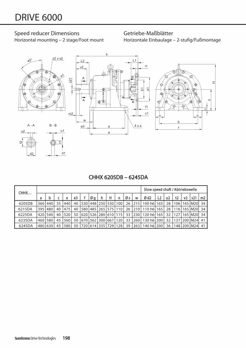
CCHHHHXX 66220055DDBB –– 66224455DDAA
119988
DRIVE 6000
Speed reducer Dimensions Getriebe-MaßblätterHorizontal mounting – 2 stage/Foot mount Horizontale Einbaulage – 2-stufig/Fußmontage
aa bb cc ee ee33 ff ØØ gg hh HH nn ØØ ss ww ØØ dd22 LL22 uu22 tt22 vv22 ss2211 mm22
6205DB 360 440 35 440 40 530 448 250 530 100 26 215 100 h6 165 28 106 165 M20 34
6215DA 395 480 40 475 40 580 485 265 575 110 26 210 110 h6 165 28 116 165 M20 34
6225DA 420 540 40 520 50 620 526 280 610 115 33 230 120 h6 165 32 127 165 M20 34
6235DA 460 580 45 560 50 670 562 300 667 120 33 260 130 h6 200 32 137 200 M24 41
6245DA 480 630 45 580 50 720 614 335 729 128 39 263 140 h6 200 36 148 200 M24 41
SSllooww ssppeeeedd sshhaafftt // AAbbttrriieebbsswweelllleeCCHHHHXX……

119999
DRIVE 6000
Speed reducer Dimensions Getriebe-MaßblätterHorizontal mounting – 2 stage/Foot mount Horizontale Einbaulage – 2-stufig/Fußmontage
ØØ aa11 ØØ bb11 cc11 ØØ ee11 ff11 kk ØØ ss11 ØØ dd11 l1 LL11** uu11 tt1190/A200 200 130H8 11 165 4,5 705 11 24 F7 14 50 8 Js9 27,3 276
100/112/A250 250 180H8 13 215 715 28 F7 18 60 8 Js9 31,3 278132/A300 300 230H8 17 265 741 38 F7 23 80 10 Js9 41,3 28390/A200 200 130H8 11 165 4,5 732 11 24 F7 14 50 8 Js9 27,3 357
100/112/A250 250 180H8 13 215 742 28 F7 18 60 8 Js9 31,3 359132/A300 300 230H8 17 265 768 38 F7 23 80 10 Js9 41,3 36490/A200 200 130H8 11 165 4,5 773 11 24 F7 14 50 8 Js9 27,3 432
100/112/A250 250 180H8 13 215 783 28 F7 18 60 8 Js9 31,3 434132/A300 300 230H8 17 265 809 38 F7 23 80 10 Js9 41,3 439
100/112/A250 250 180H8 14 215 864 28 F7 18 60 8 Js9 31,3 552132/A300 300 230H8 265 876 38 F7 23 80 10 Js9 41,3 557160/A350 350 250H8 300 6 922 18 42 F7 47 110 12 Js9 45,3 562
100/112/A250 250 180H8 14 215 902 28 F7 18 60 8 Js9 31,3 660132/A300 300 230H8 265 924 38 F7 23 80 10 Js9 41,3 665160/A350 350 250H8 300 6 960 18 42 F7 47 110 12 Js9 45,3 670
kkgg
6235DA
6245DA
L* = Length of motor shaft
L* = Länge der Motorwelle
HHiigghh ssppeeeedd sshhaafftt ppoorrttiioonn // AAnnttrriieebbsssseeiittee
6225DA
IInnppuutt eelleemmeennttAAnnttrriieebbsszzuubbeehhöörr
6215DA
6205DB
CCHHHHXX……
5 14
5 14
5 14
5 1416
5 1416
Keys and keyways according to DIN 6885 page 1Tolerances according to DIN ISO 286 part 2Where installation space is restricted, contact Sumitomo Drive Technologies for additional dimensions.
Passfedern nach DIN 6885 Seite 1Toleranzen nach DIN ISO 286 Teil 2Nicht tolerierte Maße sind bei beengter Einbausituation im Werk nachzufragen.
Spee
d Re
duce
r Dim
ensi
ons
Get
rieb
e-M
aßb
lätt
er

CCNNFF 66006600DDAAEE -- 66112255DDBBEE
220000
DRIVE 6000
Speed reducer Dimensions Getriebe-MaßblätterHorizontal mounting – 2 stage/Flange mount Horizontale Einbaulage – 2-stufig/Flanschmontage
CCNNFF…… ØØ bb22 ØØ ee22 ff22 Ø g II22 k ss22 xx22 zz22 AAEE22
80 g6 98 4 110 73 178 M6 22 6 0°
80 g6 98 4 110 84 194 M6 22 6 0°
105 g6 134 6 150 129 258 M8 25 8 22,5°
105 g6 134 6 150 139 283 M8 26 8 22,5°
140 g6 180 14 204 154 308 M10 30 6 0°
140 g6 180 14 204 154 327 M10 30 6 0°
6060DAE6065DAE
6120DBE6125DBE
6090DAE6095DAE
6100DAE6105DAE
6120DAE6125DAE
6070DAE6075DAE
ØØdd22 LL22 uu22 tt22 vv vv22 ss2211 mm22 ØØdd11 LL11 uu11 tt11 vv11 ss1111 mm11
14 k6 30 5 16 2,5 25 M5 16 12 k6 25 4 13,5 22 M4 8 4,5
20 k6 40 6 22,5 4 32 M6 16 12 k6 25 4 13,5 22 M4 8 4,5
25 k6 50 8 28 3,5 40 M10 20 12 k6 25 4 13,5 22 M4 8 10
30 k6 60 8 33 3,5 50 M10 20 12 k6 25 4 13,5 22 M4 8 12
35 k6 70 10 38 3,5 56 M12 24 12 k6 25 4 13,5 22 M4 8 22
35 k6 70 10 38 7 56 M12 24 14 k6 25 5 16 21 M5 10 25
CCNNFF....
6120DAE6125DAE
6120DBE6125DBE
kkgg
6070DAE6075DAE
6090DAE6095DAE
6100DAE6105DAE
6060DAE6065DAE
SSllooww ssppeeeedd sshhaafftt // AAbbttrriieebbsswweellllee HHiigghh ssppeeeedd sshhaafftt // AAnnttrriieebbsswweellllee

220011
DRIVE 6000
Speed reducer Dimensions Getriebe-MaßblätterHorizontal mounting – 2 stage/Flange mount Horizontale Einbaulage – 2-stufig/Flanschmontage
CCHHFF.... ØØbb22 ØØee22 ff22 Øg II22 k ss22 xx22 zz22 AAEE22
165 g6 205 16 230 208 394 M10 31 6 0°
165 g6 205 16 230 208 400 M10 31 6 0°
165 g6 205 16 230 208 400 M10 31 6 0°
200 g6 270 10 300 222 440 M12 36 6 30°
6130DBE6135DBE
6130DCE6135DCE
6140DCE6145DCE
6160DB6165DB
ØØdd22 LL22 uu22 tt22 vv vv22 ss2211 mm22 ØØdd11 LL11 uu11 tt11 vv11 ss1111 mm11
50 k6 100 14 53,5 10 80 M16 30 14 k6 25 5 16 21 M5 10 39
50 k6 100 14 53,5 10 80 M16 30 14 k6 25 5 16 21 M5 10 40
50 k6 100 14 53,5 10 80 M16 30 14 k6 25 5 16 21 M5 10 40
60 h6 90 18 64 0 80 M10 20 14 k6 25 5 16 21 M5 10 70
6130DBE6135DBE
6130DCE6135DCE
6140DCE6145DCE
6160DB6165DB
CCHHFFSSllooww ssppeeeedd sshhaafftt // AAbbttrriieebbsswweellllee HHiigghh ssppeeeedd sshhaafftt // AAnnttrriieebbsswweellllee
kkgg
Only size/nur Größe6160DB, 6165DB
CCHHFF 66113300DDBBEE -- 66116655DDBB
Keys and keyways according to DIN 6885 page 1Tolerances according to DIN ISO 286 part 2Where installation space is restricted, contact Sumitomo Drive Technologies for additional dimensions.
Passfedern nach DIN 6885 Seite 1Toleranzen nach DIN ISO 286 Teil 2Nicht tolerierte Maße sind bei beengter Einbausituation im Werk nachzufragen.

CCHHFF 66116600DDCC -- 66119955DDBB
220022
DRIVE 6000
Speed reducer Dimensions Getriebe-MaßblätterHorizontal mounting – 2 stage/Flange mount Horizontale Einbaulage – 2-stufig/Flanschmontage
CCHHFF…… ØØ bb22 ØØ ee22 ff22 ØØ gg II22 kk LL44 ss22 xx22 zz22 AAEE22
200 g6 270 10 300 222 463 228 M12 35 6 30°
250 g6 300 12 340 262 510 243 M12 41 8 22,5°
280 g6 330 12 370 299 577 258 M12 38 8 22,5°
320 g6 380 10 430 365 629 284 M12 41 12 15°
320 g6 380 10 430 365 653 284 M12 41 12 15°6190DB6195DB
6180DB6185DB
6190DA6195DA
6170DC6175DC
6160DC6165DC
Ødd22 LL22 uu22 tt22 vv22 ss2211 mm22 ØØdd11 LL11 uu11 tt11 vv11 ss1111 mm11
60 h6 90 18 64 80 M10 20 19 k6 35 6 21,5 27 M6 12 82
70 h6 90 20 74.5 80 M12 24 19 k6 35 6 21,5 27 M6 12 105
80 h6 110 22 85 100 M12 24 22 k6 40 6 24,5 34 M8 16 146
95 h6 135 25 100 125 M20 34 19 k6 35 6 21,5 27 M6 12 201
95 h6 135 25 100 125 M20 34 22 h6 40 6 24,5 34 M8 16 205
6180DB6185DB
6190DA6195DA
6170DC6175DC
6160DC6165DC
CCHHFF.... kkgg
6190DB6195DB
SSllooww ssppeeeedd sshhaafftt // AAbbttrriieebbsswweellllee HHiigghh ssppeeeedd sshhaafftt // AAnnttrriieebbsswweellllee

220033
DRIVE 6000
Speed reducer Dimensions Getriebe-MaßblätterHorizontal mounting – 2 stage/Flange mount Horizontale Einbaulage – 2-stufig/Flanschmontage
CCHHFF…… ØØ bb22 ØØ ee22 ff22 ØØ gg II22 kk LL44 ss22 xx22 zz22 AAEE22
6205DB 360 g6 405 20 448 410 705 - M16 56 12 15°6215DA 390 g6 440 20 485 423 731 - M18 56 12 15°6225DA 420 g6 475 20 526 454 773 - M20 64 12 15°6225DB 420 g6 475 20 526 454 860 - M20 64 12 15°6235DA 455 g6 510 20 562 505 883 - M20 65 12 15°6245DA 500 g6 560 25 614 529 921 - M24 65 12 15°6255DA 540 g6 610 30 670 616 1081 - M24 91 12 15°6265DA 570 g6 660 40 736 712 1243 - M30 85 12 15°6275DA 680 g6 820 50 950 919 1505 - M30 85 12 15°
Ødd22 LL22 uu22 tt22 vv22 ss2211 mm22 ØØdd11 LL11 uu11 tt11 vv11 ss1111 mm116205DB 100 h6 165 28 106 165 M20 34 22 h6 40 6 24,5 34 M8 16 2276215DA 110 h6 165 28 116 165 M20 34 22 h6 40 6 24,5 34 M8 16 3066225DA 120 h6 165 32 127 165 M20 34 22 h6 40 6 24,5 34 M8 16 3576225DB 120 h6 165 32 127 165 M20 34 35 h6 55 10 38 50 M8 16 4046235DA 130 h6 200 32 137 200 M24 41 30 h6 45 8 33 45 M8 16 4686245DA 140 h6 200 36 148 200 M24 41 30 h6 45 8 33 45 M8 16 5746255DA 160 h6 240 40 169 240 M30 52 35 h6 55 10 38 50 M8 16 8476265DA 170 h6 300 40 179 300 M30 52 45 h6 70 14 48,5 70 M10 18 11706275DA 180 h6 330 45 190 330 M30 52 45 h6 70 14 48,5 70 M10 18 2160
CCHHFF.... kkgg SSllooww ssppeeeedd sshhaafftt // AAbbttrriieebbsswweellllee HHiigghh ssppeeeedd sshhaafftt // AAnnttrriieebbsswweellllee
CCHHFF 66220055DDBB -- 66227755DDAA
Keys and keyways according to DIN 6885 page 1Tolerances according to DIN ISO 286 part 2Where installation space is restricted, contact Sumitomo Drive Technologies for additional dimensions.
Passfedern nach DIN 6885 Seite 1Toleranzen nach DIN ISO 286 Teil 2Nicht tolerierte Maße sind bei beengter Einbausituation im Werk nachzufragen.
Spee
d Re
duce
r Dim
ensi
ons
Get
rieb
e-M
aßb
lätt
er

CCNNFFXX 66006600DDAAEE -- 66112255DDBBEE
220044
DRIVE 6000
Speed reducer Dimensions Getriebe-MaßblätterHorizontal mounting – 2 stage/Flange mount Horizontale Einbaulage – 2-stufig/Flanschmontage
ØØ bb22 ØØ ee22 ff22 Ø g II22 ss22 xx22 zz22 AAEE22 ØØ dd22 LL22 uu22 tt22 vv vv22 ss2211 mm22
80 g6 98 4 110 73 M6 22 6 0° 14 k6 30 5 16 2,5 25 M 5 16
80 g6 98 4 110 84 M6 22 6 0° 20 k6 40 6 22,5 4 32 M 6 16
105 g6 134 6 150 129 M8 25 8 22,5° 25 k6 50 8 28 3,5 40 M 10 20
105 g6 134 6 150 139 M8 26 8 22,5° 30 k6 60 8 33 3,5 50 M 10 20
140 g6 180 14 204 154 M10 30 6 0° 35 k6 70 10 38 3,5 56 M 12 24
140 g6 180 14 204 154 M10 30 6 0° 35 k6 70 10 38 7 56 M 12 246120DBE6125DBE
6090DAE6095DAE
6100DAE6105DAE
6120DAE6125DAE
6070DAE6075DAE
6060DAE6065DAE
SSllooww ssppeeeedd sshhaafftt // AAbbttrriieebbsswweelllleeCCNNFFXX……

220055
DRIVE 6000
Speed reducer Dimensions Getriebe-MaßblätterHorizontal mounting – 2 stage/Flange mount Horizontale Einbaulage – 2-stufig/Flanschmontage
ØØ aa11 ØØ bb11 cc11 ØØ ee11 ff11 kk ØØ ss11 ØØ dd11 l1 LL11** uu11 tt11
63/A140 140 95 H8 115 9 11 F7 7 23 4 Js9 12,871/C105 105 70 H8 85 4,5 188 6,671/C140 140 95 H8 115 9
63/A140 140 95 H8 115 9 11 F7 7 23 4 Js9 12,8 771/C105 105 70 H8 11 85 4,5 6,6 671/C140 140 95 H8 115 9 7
63/A140 140 95 H8 115 9 11 F7 7 23 4 Js9 12,871/C105 105 70 H8 85 6,671/C140 140 95 H8 115 9
63/A140 140 95 H8 115 9 11 F7 7 23 4 Js9 12,871/C105 105 70 H8 85 6,671/C140 140 95 H8 115 9
63/A140 140 95 H8 115 9 11 F7 7 23 4 Js9 12,871/C105 105 70 H8 85 6,671/C140 140 95 H8 115 9
63/A140 140 95 H8 115 9 11 F7 6 23 4 Js9 12,871/A160 160 110 H8 130 9 14 F7 9 30 5 Js9 16,380/C120 120 80 H8 13 100 6,680/C160 160 110 H8 130 9 3390/A200 200 130 H8 165 11 3490/C140 140 95 H8 13 115 3290/C160 160 110 H8 130 3390/A200 200 130 H8 165 11 34
kkgg
L* = Length of motor shaft
L* = Länge der Motorwelle
HHiigghh ssppeeeedd sshhaafftt ppoorrttiioonn // AAnnttrriieebbsssseeiittee
17
16,35 Js9
5 Js9 16,3
30
263
309
14 F7 9 30
6120DA6125DA
14 F7 9
19914 F7
4,5
11
11 313
4,5
30 5 Js9
IInnppuutt eelleemmeennttAAnnttrriieebbsszzuubbeehhöörr
6120DB6125DB
6070DA6075DA
6060DA6065DA
CCNNFFXX……
6090DA6095DA
6100DA6105DA
11
5 Js9 16,3
9
11 4,5 287
9
14 F7 9
14 F7
16,3
5 Js9 16,3
11
4,5
327
35312
12
30
6
32
28
14
21,8
24 F7 14 50 8 Js9 27,3
19 F7 12 40 6 Js9
Keys and keyways according to DIN 6885 page 1Tolerances according to DIN ISO 286 part 2Where installation space is restricted, contact Sumitomo Drive Technologies for additional dimensions.
Passfedern nach DIN 6885 Seite 1Toleranzen nach DIN ISO 286 Teil 2Nicht tolerierte Maße sind bei beengter Einbausituation im Werk nachzufragen.
Spee
d Re
duce
r Dim
ensi
ons
Get
rieb
e-M
aßb
lätt
er

Only size/nur Größe6160DB, 6165DB
CCHHFFXX 66113300DDBBEE -- 66116655DDBB
220066
DRIVE 6000
Speed reducer Dimensions Getriebe-MaßblätterHorizontal mounting – 2 stage/Flange mount Horizontale Einbaulage – 2-stufig/Flanschmontage
ØØ bb22 ØØ ee22 ff22 ØØ gg ll22 ss22 xx22 zz22 AAEE22 ØØ dd22 LL22 uu22 tt22 vv vv22 ss2211 mm22
165 g6 205 16 230 208 M10 31 6 0° 50 k6 100 14 53,5 10 80 M16 30
165 g6 205 16 230 208 M10 31 6 0° 50 k6 100 14 53,5 10 80 M16 30
165 g6 205 16 230 208 M10 31 6 0° 50 k6 100 14 53,5 10 80 M16 30
200 g6 270 10 300 222 M12 36 6 30° 60 h6 90 18 64 0 80 M10 206160DB6165DB
SSllooww ssppeeeedd sshhaafftt // AAbbttrriieebbsswweellllee
6130DCE6135DCE
6140DCE6145DCE
6130DBE6135DBE
CCHHFFXX……

220077
DRIVE 6000
Speed reducer Dimensions Getriebe-MaßblätterHorizontal mounting – 2 stage/Flange mount Horizontale Einbaulage – 2-stufig/Flanschmontage
ØØ aa11 ØØ bb11 cc11 ØØ ee11 ff11 kk ØØ ss11 ØØ dd11 l1 LL11** uu11 tt11
63/A140 140 95 H8 115 11 F7 6 23 4 Js9 12,871//A160 160 110 H8 130 14 F7 9 30 5 Js9 16,380/C120 120 80 H8 13 100 6,680/C160 160 110 H8 130 9 4680/A200 200 130 H8 165 11 5090/C140 140 95 H8 13 115 4590/C160 160 110 H8 130 4690/A200 200 130 H8 165 11 50
71/A160 160 110 H8 11 130 408 9 14 F7 9 30 5 Js9 16,380/C120 120 80 H8 13 100 6,680/C160 160 110 H8 130 9 6 Js9 21,8 4680/A200 200 130 H8 165 11 5090/C140 140 95 H8 13 115 4590/C160 160 110 H8 130 14 27,3 4690/A200 200 130 H8 165 11 50
100/112/C160 160 110 H8 14 130 5 444 9 28 F7 18 60 31,3 46,5
71/A160 160 110 H8 11 130 408 9 14 F7 9 30 5 Js9 16,380/C120 120 80 H8 13 100 6,680/C160 160 110 H8 130 9 12 6 Js9 21,8 4780/A200 200 130 H8 165 11 5090/C140 140 95 H8 13 115 4690/C160 160 110 H8 130 24 F7 14 27,3 4790/A200 200 130 H8 165 11 50
100/112/C160 160 110 H8 14 130 5 9 28 F7 18 60 31,3 47
71/A160 160 110 H8 11 130 448 9 14 F7 9 30 5 Js9 16,380/C120 120 80 H8 13 100 6,680/C160 160 110 H8 130 9 6 Js9 8780/A200 200 130 H8 165 11 9190/C140 140 95 H8 13 115 8690/C160 160 110 H8 130 14 8790/A200 200 130 H8 165 11 91
100/112/C160 160 110 H8 14 130 5 484 9 28 F7 18 60 31,3 88
9
40
50
12
24 F7
9
40
50
21,8
19 F7
19 F76160DB6165DB
4,5
433
474
4,56140DC6140DC
12
12
12
12
19 F7
24 F7
126130DC6135DC
12 4,5434
912
IInnppuutt eelleemmeennttAAnnttrriieebbsszzuubbeehhöörr
12
14
6 Js9
8Js9
394
4,5
9
40
50
CCHHFFXX……
11
19 F7
HHiigghh ssppeeeedd sshhaafftt ppoorrttiioonn // AAnnttrriieebbsssseeiittee
6130DB6135DB
420
24 F7
12
12
9
kkgg
L* = Length of motor shaft
L* = Länge der Motorwelle
45
8 Js9
45
8 Js9
40
50
8 Js9
46
86
21,8
27,3
27,3
Keys and keyways according to DIN 6885 page 1Tolerances according to DIN ISO 286 part 2Where installation space is restricted, contact Sumitomo Drive Technologies for additional dimensions.
Passfedern nach DIN 6885 Seite 1Toleranzen nach DIN ISO 286 Teil 2Nicht tolerierte Maße sind bei beengter Einbausituation im Werk nachzufragen.
Spee
d Re
duce
r Dim
ensi
ons
Get
rieb
e-M
aßb
lätt
er

CCHHFFXX 66116600DDCC -- 66119955DDBB
220088
DRIVE 6000
Speed reducer Dimensions Getriebe-MaßblätterHorizontal mounting – 2 stage/Flange mount Horizontale Einbaulage – 2-stufig/Flanschmontage
ØØ aa11 ØØ bb11 cc11 ØØ ee11 ff11 kk ØØ ss11 ØØ dd11 LL11** uu11 tt11
80/A200 19 F7 12 40 6 Js9 21,890/A200 24 F7 14 50 27,3
100/112/C160 160 110 H8 130 9 95100/112/A250 250 180 H8 215 14 102
80/A200 19 F7 12 40 6 Js9 21,890/A200 24 F7 14 50 27,3
100/112/C160 160 110 H8 130 9 8 Js9 129100/112/A250 250 180 H8 215 14 136
90/A200 200 130 H8 11 165 4,5 577 11 24 F7 14 50 27,3 180100/112/A250 250 180 H8 13 215 587 28 F7 18 60 31,3 182
132/A300 300 230 H8 17 265 613 38 F7 23 80 10 Js9 14,3 18780/A200 635 19 F7 12 40 6 Js9 21,8 24390/A200 635 24 F7 14 50 27,3
100/112/C160 160 110 H8 130 9 8 Js9100/112/A250 250 180 H8 215 14 257
90/A200 200 130 H8 11 165 4,5 653 11 24 F7 14 50 27,3 247100/112/A250 250 180 H8 13 215 663 28 F7 18 60 31,3 250
132/A300 300 230 H8 17 265 689 38 F7 23 80 10 Js9 14,3 255
60
6190DA6195DA
6190DB6195DB
200
200
14
165 4,5
4,5130 H8
525 18
11
60
130 H8
HHiigghh ssppeeeedd sshhaafftt ppoorrttiioonn // AAnnttrriieebbsssseeiittee
130 H8 13
478 28 F7
200 4,5165
515
IInnppuutt eelleemmeennttAAnnttrriieebbsszzuubbeehhöörr
CCHHFFXX……
6170DC6175DC
6180DB6185DB
6160DC6165DC
14 5
14 5
13
13 165
31,3
128
8 Js9
8 Js9
248
31,3
94
L* = Length of motor shaft
L* = Länge der Motorwelle
kkgg
468 11
8 Js931,318 60
18
5 14
28 F7
28 F7645
14
11
5
5
ØØ bb22 ØØ ee22 ff22 ØØ gg II22 LL44 ss22 xx22 zz22 AAEE22 ØØ dd22 LL22 uu22 tt22 vv22 ss2211 mm22
200 g6 270 10 300 222 228 M12 35 6 30° 60 h6 90 18 64 80 M10 20
250 g6 300 12 340 262 243 M12 41 8 22,5° 70 h6 90 20 74.5 80 M12 24
280 g6 330 12 370 299 258 M12 42 8 22,5° 80 h6 110 22 85 100 M12 24
320 g6 380 10 430 365 284 M12 41 12 15° 95 h6 135 25 100 125 M20 34
320 g6 380 10 430 365 284 M12 41 12 15° 95 h6 135 25 100 125 M20 34
CCHHFFXX……SSllooww ssppeeeedd sshhaafftt // AAbbttrriieebbsswweellllee
6190DB6195DB
6180DB6185DB
6190DA6195DA
6170DC6175DC
6160DC6165DC

ØØ bb22 ØØ ee22 ff22 ØØ gg II22 ss22 xx22 zz22 AAEE22 ØØ dd22 LL22 uu22 tt22 vv22 ss2211 mm22
6205DB 360 405 20 448 410 M16 65.5 12 15° 100 165 28 106 165 M20 34
6215DA 390 440 20 485 423 M18 62 12 15° 110 165 28 116 165 M20 34
6225DA 420 475 20 526 454 M20 61 12 15° 120 165 32 127 165 M20 34
6235DA 455 510 20 562 505 M20 58.5 12 15° 130 200 32 137 200 M24 416245DA 500 560 25 614 529 M24 57 12 15° 140 200 36 148 200 M24 41
SSllooww ssppeeeedd sshhaafftt // AAbbttrriieebbsswweelllleeCCHHFFXX……
CCHHFFXX 66220055DDBB -- 66224455DDAA
220099
DRIVE 6000
Speed reducer Dimensions Getriebe-MaßblätterHorizontal mounting – 2 stage/Flange mount Horizontale Einbaulage – 2-stufig/Flanschmontage
ØØ aa11 ØØ bb11 cc11 ØØ ee11 ff11 kk ØØ ss11 ØØ dd11 LL11** uu11 tt11
90/A 200 200 130 H8 11 165 4,5 705 11 24 F7 14 50 27,3 270100/112/A 250 250 180 H8 13 215 715 28 F7 18 60 31,3 272
132/A 300 300 230 H8 17 265 741 38 F7 23 80 10 Js9 41,3 27790/A 200 200 130 H8 11 165 4,5 732 11 24 F7 14 50 27,3 351
100/112/A 250 250 180 H8 13 215 742 28 F7 18 60 31,3 353132/A 300 300 230 H8 17 265 768 38 F7 23 80 10 Js9 41,3 35890/A 200 200 130 H8 11 165 4,5 773 11 24 F7 14 50 27,3 426
100/112/A 250 250 180 H8 13 215 783 28 F7 18 60 31,3 428132/A 300 300 230 H8 17 265 809 38 F7 23 80 10 Js9 41,3 433
100/112/A 250 250 180 H8 14 215 864 28 F7 18 60 8 Js9 31,3 540132/A 300 300 230 H8 16 265 876 38 F7 23 80 10 Js9 41,3 545160/A 350 350 250 H8 16 300 6 922 18 42 F7 47 110 12 Js9 45,3 550
100/112/A 250 250 180 H8 14 215 902 28 F7 18 60 8 Js9 31,3 648132/A 300 300 230 H8 16 265 924 38 F7 23 80 10 Js9 41,3 653160/A 350 350 250 H8 16 300 6 960 18 42 F7 47 110 12 Js9 45,3 658
5
8 Js9
8 Js9
8 Js96225DA
L* = Length of motor shaft
L* = Länge der Motorwelle
kkgg
5
HHiigghh ssppeeeedd sshhaafftt ppoorrttiioonn // AAnnttrriieebbsssseeiitteeIInnppuutt eelleemmeennttAAnnttrriieebbsszzuubbeehhöörr
CCHHFFXX……
6205DB
6215DA
14
6235DA
14
14
14
14
6245DA
5
5
5
Keys and keyways according to DIN 6885 page 1Tolerances according to DIN ISO 286 part 2Where installation space is restricted, contact Sumitomo Drive Technologies for additional dimensions.
Passfedern nach DIN 6885 Seite 1Toleranzen nach DIN ISO 286 Teil 2Nicht tolerierte Maße sind bei beengter Einbausituation im Werk nachzufragen.
Spee
d Re
duce
r Dim
ensi
ons
Get
rieb
e-M
aßb
lätt
er

CCNNVV 66006600DDAAEE -- 66112255DDBBEE
221100
DRIVE 6000
Speed reducer Dimensions Getriebe-MaßblätterUniversal mounting – 2 stage/Flange mount Beliebige Einbaulage – 2-stufig/Flanschmontage
CCNNVV…… ØØ aa22 ØØ bb22 cc22 ØØ ee22 ff22 ØØ gg II22 kk ØØ ss22 zz22 AAEE22
120 80 j6 8 100 3 110 39 178 9 6 30°
160 110 j6 9 130 3 110 52 194 11 4 45°
160 110 j6 9 130 3 150 63 258 11 4 45°
160 110 j6 9 130 3 150 73 283 11 4 45°
200 130 j6 13 165 4 204 84 308 11 6 30°
200 130 j6 13 165 4 204 84 327 11 6 30°
6060DAE6065DAE
6120DBE6125DBE
6090DAE6095DAE
6100DAE6105DAE
6120DAE6125DAE
6070DAE6075DAE
ØØdd22 LL22 uu22 tt22 vv vv22 ss2211 mm22 ØØdd11 LL11 uu11 tt11 vv11 ss1111 mm11
14 k6 25 5 16 2,5 25 M5 16 12 k6 25 4 13,5 22 M4 8 5
20 k6 40 6 22,5 4 32 M6 16 12 k6 25 4 13,5 22 M4 8 6,7
25 k6 50 8 27 3,5 40 M10 20 12 k6 25 4 13,5 22 M4 8 11
30 k6 60 8 33 3,5 50 M10 20 12 k6 25 4 13,5 22 M4 8 13
35 k6 70 10 38 7 56 M12 24 12 k6 25 4 13,5 22 M4 8 25
35 k6 70 10 38 7 56 M12 24 14 k6 25 5 16 21 M5 10 29
kkgg
6070DAE6075DAE
6090DAE6095DAE
6100DAE6105DAE
6060DAE6065DAE
SSllooww ssppeeeedd sshhaafftt // AAbbttrriieebbsswweellllee HHiigghh ssppeeeedd sshhaafftt // AAnnttrriieebbsswweelllleeCCNNVV....
6120DAE6125DAE
6120DBE6125DBE

221111
DRIVE 6000
Speed reducer Dimensions Getriebe-MaßblätterUniversal mounting – 2 stage/Flange mount Beliebige Einbaulage – 2-stufig/Flanschmontage
CCHHVV…… ØØ aa22 ØØ bb22 cc22 ØØ ee22 ff22 ØØ gg II22 kk ØØ ss22 zz22 AAEE22
260 200 f8 15 230 4 230 106 394 11 6 0°
260 200 f8 15 230 4 230 106 400 11 6 0°
260 200 f8 15 230 4 230 106 400 11 6 0°
340 270 f8 20 310 4 300 89 440 11 6 0°
6130DBE6135DBE
6140DCE6140DCE
6160DB6165DB
6130DCE6135DCE
ØØdd22 LL22 uu22 tt22 vv vv22 ss2211 mm22 ØØdd11 LL11 uu11 tt11 vv11 ss1111 mm11
50 k6 100 14 53,5 10 80 M16 30 14 k6 25 5 16 21 M5 10 43
50 k6 100 14 53,5 10 80 M16 30 14 k6 25 5 16 21 M5 10 44
50 k6 100 14 53,5 10 80 M16 30 14 k6 25 5 16 21 M5 10 44
60 h6 90 18 64 0 80 M10 20 14 k6 25 5 16 21 M5 10 82
CCNNVV....SSllooww ssppeeeedd sshhaafftt // AAbbttrriieebbsswweellllee HHiigghh ssppeeeedd sshhaafftt // AAnnttrriieebbsswweellllee
kkgg
6130DBE6135DBE
6130DCE6135DCE
6140DCE6145DCE
6160DB6165DB
Only size/nur Größe6160DB, 6165DB
Only size/nur Größe6130DB - 6145DC
CCHHVV 66113300DDBBEE -- 66116655DDBB
Keys and keyways according to DIN 6885 page 1Tolerances according to DIN ISO 286 part 2Where installation space is restricted, contact Sumitomo Drive Technologies for additional dimensions.
Passfedern nach DIN 6885 Seite 1Toleranzen nach DIN ISO 286 Teil 2Nicht tolerierte Maße sind bei beengter Einbausituation im Werk nachzufragen.
Spee
d Re
duce
r Dim
ensi
ons
Get
rieb
e-M
aßb
lätt
er

CCHHVV 66116600DDCC -- 66119955DDBB
221122
DRIVE 6000
Speed reducer Dimensions Getriebe-MaßblätterHorizontal mounting – 2 stage/Flange mount Horizontale Einbaulage – 2-stufig/Flanschmontage
CCHHVV…… ØØ aa22 ØØ bb22 cc22 ØØ ee22 ff22 ØØ gg II22 LL44 kk ØØ ss22 zz22 AAEE22
340 270 f8 20 310 4 300 89 228 463 11 6 0°
400 316 f8 22 360 5 340 94 243 510 14 8 22,5°
430 345 f8 22 390 5 370 110 258 577 18 8 22,5°
490 400 f8 30 450 6 430 145 284 629 18 12 15°
490 400 f8 30 450 6 430 145 284 653 18 12 15°6190DB6195DB
6180DB6185DB
6190DA6195DA
6170DC6175DC
6160DC6165DC
Ø d2 LL22 uu22 tt22 vv22 ss2211 mm22 ØØ dd11 LL11 uu11 tt11 vv11 ss1111 mm11
60 h6 80 18 64 80 M10 20 19 k6 35 6 21,5 27 M6 12 90
70 h6 84 20 74.5 80 M12 24 19 k6 35 6 21,5 27 M6 12 125
80 h6 100 22 85 100 M12 24 22 k6 40 6 24,5 34 M8 16 171
95 h6 125 25 100 125 M20 34 19 k6 35 6 21,5 27 M6 12 229
95 h6 125 25 100 125 M20 34 22 k6 40 6 24,5 34 M8 16 240
6180DB6185DB
6190DA6195DA
CCVVVV…… kkgg
6160DC6165DC
6170DC6175DC
6190DB6195DB
SSllooww ssppeeeedd sshhaafftt // AAbbttrriieebbsswweellllee HHiigghh ssppeeeedd sshhaafftt // AAnnttrriieebbsswweellllee

221133
DRIVE 6000
Speed reducer Dimensions Getriebe-MaßblätterHorizontal mounting – 2 stage/Flange mount Horizontale Einbaulage – 2-stufig/Flanschmontage
CCHHVV…… ØØ aa22 ØØ bb22 cc22 ØØ ee22 ff22 ØØ gg II22 LL44 kk ØØ ss22 zz22 AAEE22
6205DB 455 355 f8 30 405 5 448 204 - 705 22 8 0°6215DA 490 390 f8 35 440 7 485 203 - 731 24 8 0°6225DA 535 415 f8 35 475 10 526 210 - 773 27 8 0°6225DB 535 415 f8 35 475 10 526 210 - 860 27 8 0°6235DA 570 450 f8 40 510 10 562 250 - 883 27 8 0°6245DA 635 485 f8 40 560 10 614 250 - 921 33 8 0°6255DA 685 535 f8 45 610 10 670 295 - 1081 33 8 0°6265DA 750 570 f8 50 660 10 736 360 - 1243 39 8 0°6275DA 1160 900 f8 60 1020 10 950 355 - 1504 39 8 22,5°
Ø dd22 LL22 uu22 tt22 vv22 ss2211 mm22 ØØ dd11 LL11 uu11 tt11 vv11 ss1111 mm11
6205DB 100 h6 165 28 106 165 M20 34 22 k6 40 6 24,5 34 M8 16 2586215DA 110 h6 165 28 116 165 M20 34 22 k6 40 6 24,5 34 M8 16 3336225DA 120 h6 165 32 127 165 M20 34 22 k6 40 6 24,5 34 M8 16 4086225DB 120 h6 165 32 127 165 M20 34 35 h6 55 10 38 50 M8 16 4556235DA 130 h6 200 32 137 200 M24 41 30 h6 45 8 33 45 M8 16 5106245DA 140 h6 200 36 148 200 M24 41 30 h6 45 8 33 45 M8 16 6046255DA 160 h6 240 40 169 240 M30 52 35 h6 55 10 38 50 M8 16 9256265DA 170 h6 300 40 179 300 M30 52 45 h6 70 14 48,5 70 M10 18 12656275DA 180 h6 330 45 190 330 M30 52 45 h6 70 14 48,5 70 M10 18 2660
CCHHVV…… kkgg SSllooww ssppeeeedd sshhaafftt // AAbbttrriieebbsswweellllee HHiigghh ssppeeeedd sshhaafftt // AAnnttrriieebbsswweellllee
Keys and keyways according to DIN 6885 page 1Tolerances according to DIN ISO 286 part 2Where installation space is restricted, contact Sumitomo Drive Technologies for additional dimensions.
Passfedern nach DIN 6885 Seite 1Toleranzen nach DIN ISO 286 Teil 2Nicht tolerierte Maße sind bei beengter Einbausituation im Werk nachzufragen.
CCHHVV 66220055DDBB -- 66227755DDAA
Spee
d Re
duce
r Dim
ensi
ons
Get
rieb
e-M
aßb
lätt
er

CCNNVVXX 66006600DDAAEE -- 66112255DDBBEE
221144
DRIVE 6000
Speed reducer Dimensions Getriebe-MaßblätterUniversal mounting – 2 stage/Flange mount Beliebige Einbaulage – 2-stufig/Flanschmontage
ØØ aa22 ØØ bb22 cc22 ØØ ee22 ff22 ØØ gg ll22 ØØ ss22 zz22 AAEE22 ØØ dd22 LL22 uu22 tt22 vv vv22 ss2211 mm22
120 80 J6 8 100 3 110 39 9 6 30° 14 k6 25 5 16 2,5 25 M5 16
160 110 J6 9 130 3 110 52 11 4 45° 20 k6 40 6 23 4 32 M6 16
160 110 J6 9 130 3 150 63 11 4 45° 250 k6 50 8 27 3,5 40 M10 20
160 110 J6 9 130 3 150 73 11 4 45° 30 h6 60 8 33 3,5 50 M10 20
200 130 J6 13 165 4 204 84 11 6 30° 35 k6 70 10 38 7 56 M12 24
200 130 J6 13 165 4 204 84 11 6 30° 35 k6 70 10 38 7 56 M12 24
6120DAE6125DAE
6120DBE6125DBE
6100DAE6105DAE
SSllooww ssppeeeedd sshhaafftt // AAbbttrriieebbsswweellllee
6070DAE6075DAE
6090DAE6095DAE
6060DAE6065DAE
CCNNVVXX……

221155
DRIVE 6000
Speed reducer Dimensions Getriebe-MaßblätterUniversal mounting – 2 stage/Flange mount Beliebige Einbaulage – 2-stufig/Flanschmontage
ØØ aa11 ØØ bb11 cc11 ØØ ee11 ff11 kk ØØ ss11 ØØ dd11 l1 LL11** uu11 tt11
63/A140 140 95 H8 115 9 11 F7 7 23 4 Js9 12,871/C105 105 70 H8 85 6,671/C140 140 95 H8 115 9
63/A140 140 95 H8 115 9 11 F7 7 23 4 Js9 12,871/C105 105 70 H8 85 6,671/C140 140 95 H8 115 9
63/A140 140 95 H8 115 9 11 F7 7 23 4 Js9 12,8 1371/C105 105 70 H8 85 6,671/C140 140 95 H8 115 963/A140 140 95 H8 115 9 11 F7 7 23 4 Js9 12,871/C105 105 70 H8 85 6,671/C140 140 95 H8 115 9
63/A140 140 95 H8 115 9 11 F7 7 23 4 Js9 12,871/C105 105 70 H8 85 6,671/C140 140 95 H8 115 9
63/A140 140 95 H8 115 11 F7 6 23 4 Js9 12,871/A160 160 110 H8 130 14 F7 9 30 5 Js9 16,380/C120 120 80 H8 13 100 6,680/C160 160 110 H8 130 9 3280/A200 200 130 H8 165 11 3490/C140 140 95 H8 13 115 3190/C160 160 110 H8 130 3290/A200 200 130 H8 165 11 34
11
353
11
4,5
6090DA6095DA
6100DA6105DA
6120DA6125DA
6120DB6125DB
CCNNVVXX……HHiigghh ssppeeeedd sshhaafftt ppoorrttiioonn // AAnnttrriieebbsssseeiittee
6060DA6065DA
6070DA6075DA
IInnppuutt eelleemmeennttAAnnttrriieebbsszzuubbeehhöörr
14 F7 9
14 F7 9
16,3
L* = Length of motor shaft
L* = Länge der Motorwelle
8 Js9
30
30
30
30
16,3
16,3
16,3
16,3
4,5
4,5
11
11
11
11
188
199
263
287
313
327
4,5
4,5
14 F7 9
14 F7 9
24 F7 14
9
9
19 F7
kkgg
30
40
50
5 Js9
5 Js9
5 Js9
5 Js9
5 Js9
6 Js9
7
8
13
15
27
4,5
31
12
12
21,8
27,3
14 F7 9
12
Keys and keyways according to DIN 6885 page 1Tolerances according to DIN ISO 286 part 2Where installation space is restricted, contact Sumitomo Drive Technologies for additional dimensions.
Passfedern nach DIN 6885 Seite 1Toleranzen nach DIN ISO 286 Teil 2Nicht tolerierte Maße sind bei beengter Einbausituation im Werk nachzufragen.
Spee
d Re
duce
r Dim
ensi
ons
Get
rieb
e-M
aßb
lätt
er

Only size/nur Größe6160DB, 6165DB
Only size/nur Größe6130DB - 6145DC
CCHHVVXX 66113300DDBBEE -- 66116655DDBB
221166
DRIVE 6000
Speed reducer Dimensions Getriebe-MaßblätterHorizontal mounting – 2 stage/Flange mount Horizontale Einbaulage – 2-stufig/Flanschmontage
ØØ aa22 ØØ bb22 cc22 ØØ ee22 ff22 ØØ gg ll22 ØØ ss22 zz22 AAEE22 ØØ dd22 LL22 uu22 tt22 vv vv22 ss2211 mm22
260 200 f8 15 230 4 230 106 11 6 0° 50 k6 100 14 53,5 10 80 M16 30
260 200 f8 15 230 4 230 106 11 6 0° 50 k6 100 14 53,5 10 80 M16 30
260 200 f8 15 230 4 230 106 11 6 0° 50 k6 100 14 53,5 10 80 M16 30
340 270 f8 20 310 4 300 89 11 6 0° 60 h6 90 18 64 0 80 M10 206160DB6165DB
SSllooww ssppeeeedd sshhaafftt // AAbbttrriieebbsswweellllee
6130DCE6135DCE
6140DCE6145DCE
6130DBE6135DBE
CCHHVVXX……

221177
DRIVE 6000
Speed reducer Dimensions Getriebe-MaßblätterHorizontal mounting – 2 stage/Flange mount Horizontale Einbaulage – 2-stufig/Flanschmontage
ØØ aa11 ØØ bb11 cc11 ØØ ee11 ff11 kk ØØ ss11 ØØ dd11 l1 LL11** uu11 tt11
63/A140 140 95 H8 115 11 F7 6 23 4 Js9 12,871//A160 160 110 H8 130 14 F7 9 30 5 Js9 16,380/C120 120 80 H8 13 100 6,680/C160 160 110 H8 130 9 4780/A200 200 130 H8 165 11 5090/C140 140 95 H8 13 115 4690/C160 160 110 H8 130 4790/A200 200 130 H8 165 11 50
71/A160 160 110 H8 11 130 408 9 14 F7 9 30 5 Js9 16,380/C120 120 80 H8 13 100 6,680/C160 160 110 H8 130 9 4780/A200 200 130 H8 165 11 5090/C140 140 95 H8 13 115 4690/C160 160 110 H8 130 4790/A200 200 130 H8 165 11 50
100/112/C160 160 110 H8 14 130 5 444 9 28 F7 18 60 31,3 48
71/A160 160 110 H8 11 130 408 9 14 F7 9 30 5 Js9 16,380/C120 120 80 H8 13 100 6,680/C160 160 110 H8 130 9 12 6 Js9 4780/A200 200 130 H8 165 11 5090/C140 140 95 H8 13 115 4690/C160 160 110 H8 130 24 F7 14 4790/A200 200 130 H8 165 11 50
100/112/C160 160 110 H8 14 130 5 9 28 F7 18 60 31,3 48
71/A160 160 110 H8 11 130 448 9 14 F7 9 30 5 Js9 16,380/C120 120 80 H8 13 100 6,680/C160 160 110 H8 130 9 8880/A200 200 130 H8 165 11 9190/C140 140 95 H8 13 115 8790/C160 160 110 H8 130 8890/A200 200 130 H8 165 11 91
100/112/C160 160 110 H8 14 130 5 484 9 28 F7 18 60 31,3 89
12
149
24 F7
21,8
27,3
6 Js940
50
27,3
21,840
50
87
19 F7
19 F7
12
12
40
50
12
12
4,5
kkgg
LL** == LLeennggtthh ooff mmoottoorr sshhaafftt
LL** == LLäännggee ddeerr MMoottoorrwweellllee
46
8 Js9
8 Js9
46
46
21,8
27,3
6 Js9
IInnppuutt eelleemmeennttAAnnttrriieebbsszzuubbeehhöörr
8 Js9
21,8
27,3
12
9
40
50149
6 Js9
8Js9
CCHHVVXX……
11
19 F7
HHiigghh ssppeeeedd sshhaafftt ppoorrttiioonn // AAnnttrriieebbsssseeiittee
6130DB6135DB
420
24 F7
394
6130DC6135DC
433
12
14
4,5
19 F7
24 F7
9
9
6160DB6165DB
4,5
433
474
4,56140DC6140DC
12
12
12
12
Keys and keyways according to DIN 6885 page 1Tolerances according to DIN ISO 286 part 2Where installation space is restricted, contact Sumitomo Drive Technologies for additional dimensions.
Passfedern nach DIN 6885 Seite 1Toleranzen nach DIN ISO 286 Teil 2Nicht tolerierte Maße sind bei beengter Einbausituation im Werk nachzufragen.
Spee
d Re
duce
r Dim
ensi
ons
Get
rieb
e-M
aßb
lätt
er

CCHHVVXX 66116600DDCC -- 66119955DDBB
221188
DRIVE 6000
Speed reducer Dimensions Getriebe-MaßblätterHorizontal mounting – 2 stage/Flange mount Horizontale Einbaulage – 2-stufig/Flanschmontage
ØØ aa22 ØØ bb22 cc22 ØØ ee22 ff22 ØØ gg II22 LL44 ØØ ss22 zz22 AAEE22 ØØ dd22 LL22 uu22 tt22 vv22 ss2211 mm22
340 270 f8 20 310 4 300 89 228 11 6 0° 60 h6 90 18 64 80 M10 20
400 316 f8 22 360 5 340 94 243 14 8 22,5° 70 h6 90 20 74,5 80 M12 24
430 345 f8 22 390 5 370 110 258 18 8 22,5° 80 h6 110 22 85 100 M12 24
490 400 f8 30 450 6 430 145 284 18 12 15° 95 h6 135 25 100 125 M20 34
490 400 f8 30 450 6 430 145 284 18 12 15° 95 h6 135 25 100 125 M20 34
6160DC6165DC
6190DB6195DB
6180DB6185DB
6190DA6195DA
6170DC6175DC
SSllooww ssppeeeedd sshhaafftt // AAbbttrriieebbsswweelllleeCCHHVVXX……

221199
DRIVE 6000
Speed reducer Dimensions Getriebe-MaßblätterHorizontal mounting – 2 stage/Flange mount Horizontale Einbaulage – 2-stufig/Flanschmontage
ØØ aa11 ØØ bb11 cc11 ØØ ee11 ff11 kk ØØ ss11 ØØ dd11 ll11 LL11** uu11 tt11
80/A200 19 F7 12 40 6 Js9 21,890/A200 24 F7 14 50 27,3
100/112/C160 160 110 H8 130 9 98100/112/A250 250 180 H8 215 14 102
80/A200 19 F7 12 40 6 Js9 21,890/A200 24 F7 14 50 27,3
100/112/C160 160 110 H8 130 9 8 Js9 132100/112/A250 250 180 H8 215 14 136
90/A200 200 130 H8 11 165 4,5 577 11 24 F7 14 50 27,3 185100/112/A250 250 180 H8 13 215 587 28 F7 18 60 31,3 187
132/A300 300 230 H8 17 265 613 38 F 23 80 10 Js9 41,3 19280/A200 19 F7 12 40 6 Js9 21,8 24590/A200 24 F7 14 50 27,3 248
100/112/C160 160 110 H8 130 9 253100/112/A250 250 180 H8 215 14 257
90/A200 200 130 H8 11 165 4,5 653 11 24 F7 14 50 27,3 252100/112/A250 250 180 H8 13 215 663 28 F7 18 60 31,3 255
132/A300 300 130 H8 17 265 689 38 F7 23 80 10 Js9 41,3 2605 14
HHiigghh ssppeeeedd sshhaafftt ppoorrttiioonn // AAnnttrriieebbsssseeiittee
8 Js9
28 F7
11
645
11
14
11
97
L* = Length of motor shaft
L* = Länge der Motorwelle
31,3
131
8 Js9
kkgg
8 Js9
IInnppuutt eelleemmeennttAAnnttrriieebbsszzuubbeehhöörr
CCHHVVXX……
14 5
5
4,5130 H8 13 165
130 H8
515
525
478
635
6160DC6165DC
13 165 4684,5200
14 5
5
130 H8 13
14
28 F7
28 F7
6190DA6195DA
6190DB6195DB
200
200
6180DB6185DB
6170DC6175DC
165 4,5
18
18
18
31,3
31,3
8 Js960
60
60
Keys and keyways according to DIN 6885 page 1Tolerances according to DIN ISO 286 part 2Where installation space is restricted, contact Sumitomo Drive Technologies for additional dimensions.
Passfedern nach DIN 6885 Seite 1Toleranzen nach DIN ISO 286 Teil 2Nicht tolerierte Maße sind bei beengter Einbausituation im Werk nachzufragen.
Spee
d Re
duce
r Dim
ensi
ons
Get
rieb
e-M
aßb
lätt
er

CCHHVVXX 66220055DDBB -- 66224455DDAA
222200
DRIVE 6000
Speed reducer Dimensions Getriebe-MaßblätterHorizontal mounting – 2 stage/Flange mount Horizontale Einbaulage – 2-stufig/Flanschmontage
ØØ aa22 ØØ bb22 cc22 ØØ ee22 ff22 ØØ gg ll22 ØØ ss22 zz22 AAEE22 ØØ dd22 LL22 uu22 tt22 vv22 ss2211 mm22
6205DB 455 355 f8 30 405 5 448 204 22 8 15° 100 h6 165 28 106 165 M20 34
6215DA 490 390 f8 35 440 7 485 203 24 8 15° 110 h6 165 28 116 165 M20 34
6225DA 535 415 f8 35 475 10 526 210 27 8 15° 120 h6 165 32 127 165 M20 34
6235DA 570 450 f8 40 510 10 562 250 27 8 15° 130 h6 200 32 137 200 M24 41
6245DA 635 485 f8 40 560 10 614 250 33 8 15° 140 h6 200 36 148 200 M24 41
SSllooww ssppeeeedd sshhaafftt // AAbbttrriieebbsswweelllleeCCHHVVXX……
OOiill bbaatthh lluubbrriiccaattiioonn // ÖÖllttaauucchhsscchhmmiieerruunngg
ØØ aa11 ØØ bb11 cc11 ØØ ee11 ff11 kk ØØ ss11 ØØ dd11 LL11 LL11** uu11 tt11
90/A200 200 130 H8 11 165 4,5 705 11 24 F7 14 50 27,3 275100/112/A250 250 180 H8 13 215 715 28 F7 18 60 31,3 277
132/A300 300 230 H8 17 265 741 38 F7 23 80 10 Js9 41,3 282
90/A200 200 130 H8 11 165 4,5 732 11 24 F7 14 50 27,3 356100/112/A 250 250 180 H8 13 215 742 28 F7 18 60 31,3 358
132/A300 300 230 H8 17 265 768 38 F7 23 80 10 Js9 41,3 363
90/A200 200 130 H8 11 165 4,5 773 11 24 F7 14 50 27,3 431100/112/A250 250 180 H8 13 215 783 28 F7 18 60 31,3 433
132/A300 300 230 H8 17 265 809 38 F7 23 80 10 Js9 41,3 438
100/112/A250 250 180 H8 14 215 864 28 F7 18 60 8 Js9 31,3 549132/A300 300 230 H8 265 876 38 F7 23 80 10 Js9 41,3 554160/A350 350 250 H8 300 6 922 18 42 F7 47 110 12 Js9 45,3 559
100/112/A250 250 180 H8 14 215 902 28 F7 18 60 8 Js9 31,3 657132/A300 300 230 H8 265 924 38 F7 23 80 10 Js9 41,3 662160/A350 350 250 H8 300 6 960 18 42 F7 47 110 12 Js9 45,3 667
5 14
5 14
IInnppuutt eelleemmeennttAAnnttrriieebbsszzuubbeehhöörr
CCHHVVXX……
6205DB
6215DA
5
8 Js9
8 Js9
8 Js9
14
14
14
6235DA
kkgg
6245DA
5
5
HHiigghh ssppeeeedd sshhaafftt ppoorrttiioonn // AAnnttrriieebbsssseeiittee
16
16
6225DA
L* = Length of motor shaft
L* = Länge der
Motorwelle

Only size nur Größe6160DB6165DB
Only size nur Größe6130DB -6145DC
CCVV VV 66113300DDBBEE -- 66116655DDBB
222211
DRIVE 6000
Speed reducer Dimensions Getriebe-MaßblätterVertical mounting – 2 stage/Flange mount Vertikale Einbaulage – 2-stufig/Flanschmontage
ØØ aa22 ØØ bb22 cc22 ØØ ee22 ff22 ØØ gg ll22 kk ØØ ss22 zz22 AAEE22
260 200 f8 15 230 4 230 106 394 11 6 0°
260 200 f8 15 230 4 230 106 400 11 6 0°
260 200 f8 15 230 4 230 106 400 11 6 0°
340 270 f8 20 310 4 300 89 440 11 6 0°
CCVVVV……
6160DB6165DB
6130DCE6135DCE
6140DCE6145DCE
6130DBE6135DBE
Keys and keyways according to DIN 6885 page 1Tolerances according to DIN ISO 286 part 2Where installation space is restricted, contact Sumitomo Drive Technologies for additional dimensions.
Passfedern nach DIN 6885 Seite 1Toleranzen nach DIN ISO 286 Teil 2Nicht tolerierte Maße sind bei beengter Einbausituation im Werk nachzufragen.
ØØ dd22 LL22 uu22 tt22 vv vv22 ss2211 mm22 ØØ dd11 LL11 uu11 tt11 vv11 ss1111 mm11
50 k6 91 14 53,5 10 80 M16 30 14 k6 25 5 16 16 M5 10 43
50 k6 91 14 53,5 10 80 M16 30 14 k6 25 5 16 16 M5 10 44
50 k6 91 14 53,5 10 80 M16 30 14 k6 25 5 16 16 M5 10 44
60 h6 80 18 64 0 80 M10 20 14 k6 25 5 16 16 M5 10 826160DB6165DB
SSllooww ssppeeeedd sshhaafftt // AAbbttrriieebbsswweellllee
6130DCE6135DCE
6140DCE6145DCE
6130DBE6135DBE
HHiigghh ssppeeeedd sshhaafftt // AAnnttrriieebbsswweelllleeCCVVVV…… kkgg
Spee
d Re
duce
r Dim
ensi
ons
Get
rieb
e-M
aßb
lätt
er

* Lubrication fittings may have different positions dependent on frame size.
Die Schmierarmaturen sind, je nach Getriebegröße, an verschiedenen Positionen. Bei Fettschmierung (untersetzungsabhängig) entfallen die Schmierarmaturen.
** Frame size 6190/6195 may use 2 pumps dependent on ratio.
Bei Größe 6190DA-6195DB sind, je nach Untersetzung, auch 2 Pumpen möglich.
CCVV VV 66116600DDCC -- 66119955DDBB
DRIVE 6000
Speed reducer Dimensions Getriebe-MaßblätterVertical mounting – 2 stage/Flange mount Vertikale Einbaulage – 2-stufig/Flanschmontage
CCVVVV…… ØØ aa22 ØØ bb22 cc22 ØØ ee22 ff22 ØØ gg II22 kk rr11 rr22 ØØ ss22 zz22 AAEE22
340 270 f8 20 310 4 300 89 463 196 200 11 6 0°
400 316 f8 22 360 5 340 94 510 218 225 14 8 22,5°
430 345 f8 22 390 5 370 110 577 233 240 18 8 22,5°
490 400 f8 30 450 6 430 145 629 255 270 18 12 15°
490 400 f8 30 450 6 430 145 653 255 270 18 12 15°6190DB6195DB
6180DB6185DB
6190DA6195DA
6170DC6175DC
6160DC6165DC
Ø d2 LL22 uu22 tt22 vv22 ss2211 mm22 ØØ dd11 LL11 uu11 tt11 vv11 ss1111 mm11
60 h6 80 18 64 80 M10 20 19 k6 35 6 21,5 27 M6 12 90
70 h6 84 20 74.5 80 M12 24 19 k6 35 6 21,5 27 M6 12 125
80 h6 100 22 85 100 M12 24 22 k6 40 6 24,5 34 M8 16 171
95 h6 125 25 100 125 M20 34 19 k6 35 6 21,5 27 M6 12 229
95 h6 125 25 100 125 M20 34 22 k6 40 6 24,5 34 M8 16 240
kkgg
6160DC6165DC
6170DC6175DC
6190DB6195DB
SSllooww ssppeeeedd sshhaafftt // AAbbttrriieebbsswweellllee HHiigghh ssppeeeedd sshhaafftt // AAnnttrriieebbsswweellllee
6180DB6185DB
6190DA6195DA
CCVVVV……
222222

view rotatedgedreht gezeichnet
* Lubrication fittings may have different positions dependent on frame size.
Die Schmierarmaturen sind, je nach Getriebegröße, an verschiedenen Positionen. Bei Fettschmierung (untersetzungsabhängig) entfallen die Schmierarmaturen.
** Size 6275DA requires an external pump.
Bei der Größe 6275DA wird eine externe Pumpe eingesetzt.
CCVV VV 66220055DDBB -- 66227755DDAA
222233
DRIVE 6000
Speed reducer Dimensions Getriebe-MaßblätterVertical mounting – 2 stage/Flange mount Vertikale Einbaulage – 2-stufig/Flanschmontage
ØØ aa22 ØØ bb22 cc22 ØØ ee22 ff22 ØØ gg II22 kk rr11 rr22 ØØ ss22 zz22 AAEE22
6205DB 455 355 f8 30 405 5 448 204 705 341 287 22 8 0°
6215DA 490 390 f8 35 440 7 485 203 731 348 306 24 8 0°
6225DA 535 415 f8 35 475 10 526 210 773 352 326 27 8 0°
6225DB 535 415 f8 35 475 10 526 210 860 352 326 27 8 0°
6235DA 570 450 f8 40 510 10 562 250 883 359 344 27 8 0°
6245DA 635 485 f8 40 560 10 614 250 921 370 371 33 8 0°
6255DA 685 535 f8 45 610 10 670 295 1081 395 399 33 8 0°
6265DA 750 570 f8 50 660 10 736 360 1243 427 431 39 8 0°
6275DA 1160 900 f8 60 1020 10 950 355 1504 610 613 39 8 22,5°
CCVVVV……
Keys and keyways according to DIN 6885 page 1Tolerances according to DIN ISO 286 part 2Where installation space is restricted, contact Sumitomo Drive Technologies for additional dimensions.
Passfedern nach DIN 6885 Seite 1Toleranzen nach DIN ISO 286 Teil 2Nicht tolerierte Maße sind bei beengter Einbausituation im Werk nachzufragen.
Ø dd22 LL22 uu22 tt22 vv22 ss2211 mm22 ØØ dd11 LL11 uu11 tt11 vv11 ss1111 mm11
6205DB 100 h6 165 28 106 165 M20 34 22 k6 40 6 24,5 32 M8 16 258
6215DA 110 h6 165 28 116 165 M20 34 22 k6 40 6 24,5 32 M8 16 333
6225DA 120 h6 165 32 127 165 M20 34 22 k6 40 6 24,5 32 M8 16 408
6225DB 120 h6 165 32 127 165 M20 34 35 h6 55 10 38 50 M8 16 455
6235DA 130 h6 200 32 137 200 M24 41 30 h6 45 8 33 45 M8 16 510
6245DA 140 h6 200 36 148 200 M24 41 30 h6 45 8 33 45 M8 16 604
6255DA 160 h6 240 40 169 240 M30 52 35 h6 55 10 38 50 M8 16 925
6265DA 170 h6 300 40 179 300 M30 52 45 h6 70 14 48,5 70 M10 18 1265
6275DA 180 h6 320 45 190 330 M30 52 45 h6 70 14 48,5 70 M10 18 2660
CCVVVV…… kkgg SSllooww ssppeeeedd sshhaafftt // AAbbttrriieebbsswweellllee HHiigghh ssppeeeedd sshhaafftt // AAnnttrriieebbsswweellllee
Spee
d Re
duce
r Dim
ensi
ons
Get
rieb
e-M
aßb
lätt
er

Only size nur Größe6160DB6165DB
Only size nur Größe6130DB -6145DC
CCVV VVXX 66113300DDBBEE -- 66116655DDBBGG
222244
DRIVE 6000
Speed reducer Dimensions Getriebe-MaßblätterVertical mounting – 2 stage/Flange mount Vertikale Einbaulage – 2-stufig/Flanschmontage
ØØ aa22 ØØ bb22 cc22 ØØ ee22 ff22 ØØ gg ll22 ØØ ss22 zz22 AAEE22 ØØ dd22 LL22 uu22 tt22 vv vv22 ss2211 mm22
260 200 f8 15 230 4 230 106 11 6 0° 50 k6 91 14 53,5 10 80 M16 30
260 200 f8 15 230 4 230 106 11 6 0° 50 k6 91 14 53,5 10 80 M16 30
260 200 f8 15 230 4 230 106 11 6 0° 50 k6 91 14 53,5 10 80 M16 30
340 270 f8 20 310 4 300 89 11 6 0° 60 h6 80 18 64 0 80 M10 206160DB6165DB
SSllooww ssppeeeedd sshhaafftt // AAbbttrriieebbsswweellllee
6130DCE6135DCE
6140DCE6145DCE
6130DBE6135DBE
CCVVVVXX……

Speed reducer Dimensions Getriebe-MaßblätterVertical mounting – 2 stage/Flange mount Vertikale Einbaulage – 2-stufig/Flanschmontage
ØØ aa11 ØØ bb11 cc11 ØØ ee11 ff11 kk ØØ ss11 ØØ dd11 l1 LL11** uu11 tt11
63/A140 140 95 H8 115 11 F7 6 23 4 Js9 12,871/A160 160 110 H8 130 14 F7 9 30 5 Js9 16,380/C120 120 80 H8 100 6,680/C160 160 110 H8 130 9 4980/A200 200 130 H8 165 11 5090/C140 140 95 H8 115 4890/C160 160 110 H8 130 4990/A200 200 130 H8 165 11 50
71/A160 160 110 H8 11 130 407 9 14 F7 9 30 5 Js9 16,380/C120 120 80 H8 100 6,680/C160 160 110 H8 130 9 6 Js9 21,8 4980/A200 200 130 H8 165 11 5090/C140 140 95 H8 115 4890/C160 160 110 H8 130 14 4990/A200 200 130 H8 165 11 50
100/112/C160 160 110 H8 14 130 5 443 9 28 F7 18 60 31,3 49
71/A160 160 110 H8 11 130 407 9 14 F7 9 30 5 Js9 16,380/C120 120 80 H8 100 6,680/C160 160 110 H8 130 9 4980/A 200 200 130 H8 165 11 5090/C140 140 95 H8 115 4890/C160 160 110 H8 130 4990/A200 200 130 H8 165 11 50
100/112/C160 160 110 H8 14 130 5 443 9 28 F7 18 60 31,3 49
71/A160 160 110 H8 11 130 447 9 14 F7 9 30 5 Js9 16,380/C120 120 80 H8 100 6,680/C160 160 110 H8 130 9 9080/A200 200 130 H8 165 11 9190/C140 140 95 H8 115 8990/C160 160 110 H8 130 9090/A200 200 130 H8 165 11 91
100/112/C160 160 110 H8 14 130 5 483 9 28 F7 18 60 31,3 90
8 Js950
40
924 F7
12
14
40
950
19 F7
24 F7
kkgg
LL** == LLeennggtthh ooff mmoottoorr sshhaafftt
LL** == LLäännggee ddeerr MMoottoorrwweellllee
48
8 Js9
8 Js9
48
48
40
50
27,3
89
19 F7
19 F7
40
5024 F7 14
6 Js9
27,3
21,8
27,3
12
12 6 Js9 21,8
12
14
6 Js9
8Js9
27,3
21,8
CCVVVVXX……
11
12
19 F7
HHiigghh ssppeeeedd sshhaafftt ppoorrttiioonn // AAnnttrriieebbsssseeiittee
6130DB6135DB
419
24 F7
433
393
IInnppuutt eelleemmeennttAAnnttrriieebbsszzuubbeehhöörr
6130DC6135DC
12 433
4,5
4,5
9
9
9
6160DB6165DB
124,5
473
4,512
6140DC6140DC
222255
DRIVE 6000
Keys and keyways according to DIN 6885 page 1Tolerances according to DIN ISO 286 part 2Where installation space is restricted, contact Sumitomo Drive Technologies for additional dimensions.
Passfedern nach DIN 6885 Seite 1Toleranzen nach DIN ISO 286 Teil 2Nicht tolerierte Maße sind bei beengter Einbausituation im Werk nachzufragen.
Spee
d Re
duce
r Dim
ensi
ons
Get
rieb
e-M
aßb
lätt
er

* Lubrication fittings may have different positions dependent on frame size.
Die Schmierarmaturen sind, je nach Getriebegröße, an verschiedenen Positionen. Bei Fettschmierung (untersetzungsabhängig) entfallen die Schmierarmaturen.
** Frame size 6190/6195 may use 2 pumps dependent on ratio.
Bei Größe 6190DA-6195DB sind, je nach Untersetzung, auch 2 Pumpen möglich.
CCVV VVXX 66116600DDCC -- 66119955DDBB
222266
DRIVE 6000
Speed reducer Dimensions Getriebe-MaßblätterVertical mounting – 2 stage/Flange mount Vertikale Einbaulage – 2-stufig/Flanschmontage
Bitte Hinweise zu den Maßblättern im Kapitel „Allgemeine Information“ beachten.
ØØ aa22 ØØ bb22 cc22 ØØ ee22 ff22 ØØ gg II22 rr11 rr22 ØØ ss22 zz22 AAEE22 ØØ dd22 LL22 uu22 tt22 vv22 ss2211 mm22
340 270 f8 20 310 4 300 89 196 200 11 6 0° 60 h6 90 18 64 80 M10 20
400 316 f8 22 360 5 340 94 218 225 14 8 22,5° 70 h6 90 20 75 80 M12 24
430 345 f8 22 390 5 370 110 233 240 18 8 22,5° 80 h6 110 22 85 100 M12 24
490 400 f8 30 450 6 430 145 255 270 18 12 15° 95 h6 135 25 100 125 M20 34
490 400 f8 30 450 6 430 145 255 270 18 12 15° 95 h6 135 25 100 125 M20 34
SSllooww ssppeeeedd sshhaafftt // AAbbttrriieebbsswweelllleeCCVVVVXX……
6160DC6165DC
6190DB6195DB
6180DB6185DB
6190DA6195DA
6170DC6175DC

ØØ aa11 ØØ bb11 cc11 ØØ ee11 ff11 kk ØØ ss11 ØØ dd11 ll11 LL11** uu11 tt1180/A200 19 F7 12 40 6 Js9 21,890/A200 24 F7 14 50 27,3
100/112/C160 160 110 H8 130 9 99100/112/A250 250 180 H8 215 14 102
80/A200 19 F7 12 40 6 Js9 21,890/A200 24 F7 14 50 27,3
100/112/C160 160 110 H8 130 9 133100/112/A250 250 180 H8 215 14 136
90/A200 200 130 H8 11 165 4,5 577 11 24 F7 14 50 27,3 186100/112/A250 250 180 H8 13 215 587 28 F7 18 60 31,3 188
132/A300 300 230 H8 17 265 613 38 F7 23 80 10 Js9 41,3 19380/A200 635 19 F7 12 40 6 Js9 21,8 24690/A200 635 24 F7 14 50 27,3 249
100/112/C160 160 110 H8 130 9 254100/112/A250 250 180 H8 215 14 257
90/A200 200 130 H8 11 165 4,5 653 11 24 F7 14 50 27,3 253100/112/A250 250 180 H8 13 215 663 28 F7 18 60 31,3 256
132/A300 300 130 H8 17 265 689 38 F7 23 80 10 Js9 41,3 261
8 Js960
kkgg
18
18
18
31,3
31,3
8 Js960
8 Js960
28 F7
28 F7
6190DA6195DA
6190DB6195DB
200
200
6180DB6185DB
6170DC6175DC
165 4,5
5
130 H8 13
14
6160DC6165DC
13 165 4684,5200
14 5
11
645
11
14
11
515
525
478
IInnppuutt eelleemmeennttAAnnttrriieebbsszzuubbeehhöörr
CCVVVV……
14 5
5
4,5130 H8 13 165
130 H8
5 14
HHiigghh ssppeeeedd sshhaafftt ppoorrttiioonn // AAnnttrriieebbsssseeiittee
98
L* = Length of motor shaft
L* = Länge der Motorwelle
31,3
132
8 Js9
8 Js9
28 F7
222277
DRIVE 6000
Speed reducer Dimensions Getriebe-MaßblätterVertical mounting – 2 stage/Flange mount Vertikale Einbaulage – 2-stufig/Flanschmontage
Keys and keyways according to DIN 6885 page 1Tolerances according to DIN ISO 286 part 2Where installation space is restricted, contact Sumitomo Drive Technologies for additional dimensions.
Passfedern nach DIN 6885 Seite 1Toleranzen nach DIN ISO 286 Teil 2Nicht tolerierte Maße sind bei beengter Einbausituation im Werk nachzufragen.
Spee
d Re
duce
r Dim
ensi
ons
Get
rieb
e-M
aßb
lätt
er

DRIVE 6000
* Lubrication fittings may have different positions dependent on frame size.
Die Schmierarmaturen sind, je nach Getriebegröße, an verschiedenen Positionen. Bei Fettschmierung (untersetzungsabhängig) entfallen die Schmierarmaturen.
view rotatedgedreht gezeichnet
CCVV VVXX 66220055DDBB -- 66224455DDAA
222288
Speed reducer Dimensions Getriebe-MaßblätterVertical mounting – 2 stage/Flange mount Vertikale Einbaulage – 2-stufig/Flanschmontage
ØØ aa11 ØØ bb11 cc11 ØØ ee11 ff11 kk ØØ ss11 ØØ dd11 LL11 LL11** uu11 tt11
90/A 200 200 130 H8 11 165 4,5 705 11 24 F7 14 50 27,3 275
100/112/A 250 250 180 H8 13 215 715 28 F7 18 60 31,3 277132/A 300 300 230 H8 17 265 741 38 F7 23 80 10 Js9 41,3 282
90/A 200 200 130 H8 11 165 4,5 732 11 24 F7 14 50 27,3 356100/112/A 250 250 180 H8 13 215 742 28 F7 18 60 31,3 358
132/A 300 300 230 H8 17 265 768 38 F7 23 80 10 Js9 41,3 363
90/A 200 200 130 H8 11 165 4,5 773 11 24 F7 14 50 27,3 431100/112/A 250 250 180 H8 13 215 783 28 F7 18 60 31,3 433
132/A 300 300 230 H8 17 265 809 38 F7 23 80 10 Js9 41,3 438
100/112/A 250 250 180 H8 14 215 864 28 F7 18 60 31,3 549132/A 300 300 230 H8 265 876 38 F7 23 80 41,3 554160/A 350 350 250 H8 300 6 922 18 42 F7 47 110 12 Js9 45,3 559
100/112/A 250 250 180 H8 14 215 902 28 F7 18 60 31,3 657132/A 300 300 230 H8 265 924 38 F7 23 80 41,3 662160/A 350 350 250 H8 300 6 960 18 42 F7 47 110 12 Js9 45,3 667
CCVVVVXX……
6205DB
6215DA
516
5
5
8 Js9
8 Js9
8 Js9
IInnppuutt eelleemmeennttAAnnttrriieebbsszzuubbeehhöörr
14
14
14
14
146235DA
kkgg
8 Js9
6245DA
5
5
16
HHiigghh ssppeeeedd sshhaafftt ppoorrttiioonn // AAnnttrriieebbsssseeiittee
6225DA
8 Js9
ØØ aa22 ØØ bb22 cc22 ØØ ee22 ff22 ØØ gg ll22 rr11 rr22 ØØ ss22 zz22 AAEE22 ØØ dd22 LL22 uu22 tt22 vv22 ss2211 mm22
6205DB 455 355 f8 30 405 5 448 204 341 287 22 8 15° 100 h6 165 28 106 165 M20 346215DA 490 390 f8 35 440 7 485 203 348 306 24 8 15° 110 h6 165 28 116 165 M20 346225DA 535 415 f8 35 475 10 526 210 352 326 27 8 15° 120 h6 165 32 127 165 M20 346235DA 570 450 f8 40 510 10 562 250 359 344 27 8 15° 130 h6 200 32 137 200 M24 416245DA 635 485 f8 40 560 10 614 250 370 371 33 8 15° 140 h6 200 36 148 200 M24 41
SSllooww ssppeeeedd sshhaafftt // AAbbttrriieebbsswweelllleeCCVVVVXX……
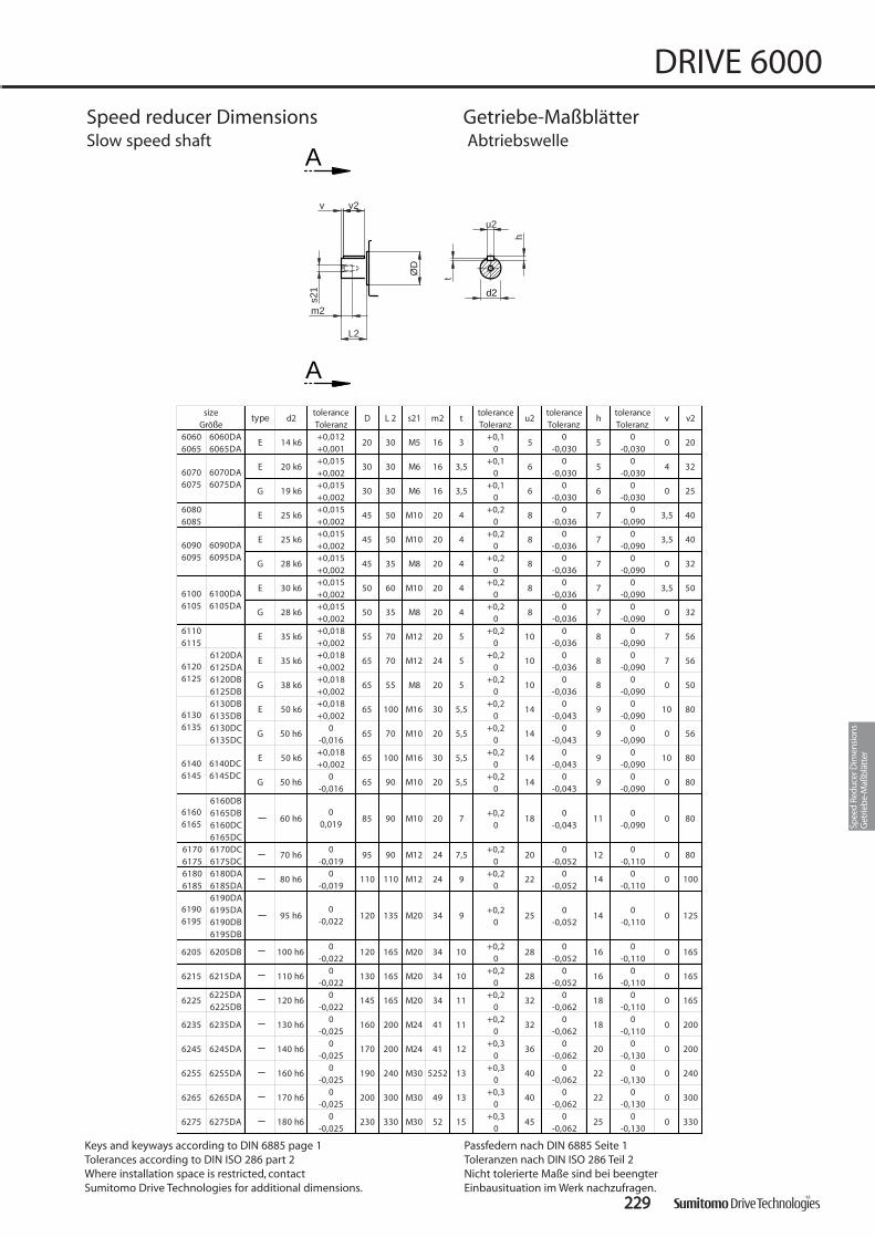
222299
DRIVE 6000
A
A
t
s21
v2v
h
m2
ØD
L2
u2
d2
Speed reducer Dimensions Getriebe-MaßblätterSlow speed shaft Abtriebswelle
Keys and keyways according to DIN 6885 page 1Tolerances according to DIN ISO 286 part 2Where installation space is restricted, contact Sumitomo Drive Technologies for additional dimensions.
Passfedern nach DIN 6885 Seite 1Toleranzen nach DIN ISO 286 Teil 2Nicht tolerierte Maße sind bei beengter Einbausituation im Werk nachzufragen.
tolerance tolerance tolerance toleranceToleranz Toleranz Toleranz Toleranz+0,012 +0,1 0 0+0,001 0 -0,030 -0,030+0,015 +0,1 0 0+0,002 0 -0,030 -0,030+0,015 +0,1 0 0+0,002 0 -0,030 -0,030+0,015 +0,2 0 0+0,002 0 -0,036 -0,090+0,015 +0,2 0 0+0,002 0 -0,036 -0,090+0,015 +0,2 0 0+0,002 0 -0,036 -0,090+0,015 +0,2 0 0+0,002 0 -0,036 -0,090+0,015 +0,2 0 0+0,002 0 -0,036 -0,090+0,018 +0,2 0 0+0,002 0 -0,036 -0,090
6120DA +0,018 +0,2 0 06125DA +0,002 0 -0,036 -0,0906120DB +0,018 +0,2 0 06125DB +0,002 0 -0,036 -0,0906130DB +0,018 +0,2 0 06135DB +0,002 0 -0,043 -0,0906130DC 0 +0,2 0 06135DC -0,016 0 -0,043 -0,090
+0,018 +0,2 0 0+0,002 0 -0,043 -0,090
0 +0,2 0 0-0,016 0 -0,043 -0,090
6160DB6165DB +0,2 0 06160DC 0 -0,043 -0,0906165DC
6170 6170DC 0 +0,2 0 06175 6175DC -0,019 0 -0,052 -0,1106180 6180DA 0 +0,2 0 06185 6185DA -0,019 0 -0,052 -0,110
6190DA6195DA +0,2 0 06190DB 0 -0,052 -0,1106195DB
0 +0,2 0 0-0,022 0 -0,052 -0,110
0 +0,2 0 0-0,022 0 -0,052 -0,110
0 +0,2 0 0-0,022 0 -0,062 -0,110
0 +0,2 0 0-0,025 0 -0,062 -0,110
0 +0,3 0 0-0,025 0 -0,062 -0,130
0 +0,3 0 0-0,025 0 -0,062 -0,130
0 +0,3 0 0-0,025 0 -0,062 -0,130
0 +0,3 0 0-0,025 0 -0,062 -0,130
v v2
200
240
80
100
125
56
80
80
300
330
165
165
165
200
80
56
56
50
80
40
40
32
32
50
20
32
25
61006105
0
0
4
0
8
8
0
0
0
0
0
0
0
0
0
0
0
0
10
0
10
0
7
7
0
3,5
3,5
0
3,5
25
16
18
18
16
20
22
22
45
28
28
32
32
36
40
40
25
10
14
14
14
14
20
22
200
230
145
160
170
190
5
18
6
6
8
8
8
10
10
52 15
300 M30 49 13
330 M30
240 M30 5252 13
200 M24 41 12
200 M24 41 11
10
165 M20 34 11
130 165 M20 34
9
120 165 M20 34 10
120 135 M20 34
M10 20 7
5
5
6
7
7
7
5,5
85 90
95 90
5,5
65 100 M16 30
65 90 M10 20
24
5,5
65 70 M10 20 5,5
65 100 M16
20
5
65 55 M8 20 5
65 70 M12
20
4
55 70 M12 20 5
50 35 M8
20
4
50 60 M10 20 4
45 35 M8
3,516
M12 24 7,5
4
M10 20 4
M10
30 30 M6
110 110 M12
45 50
45 50
30 30 M6 16
3
type D L 2
20 30 M5 16
11
12
s21
14 k6
7
7
30 k6
20 k6
19 k6
3,5
9
9
9
9
sized2
980 h6
50 k6
50 h6
E61406145
24
Größe
14
m2 t u2 h
14
30
8
8
8
6245DA 140 h6
6255DA 160 h6
6265DA 170 h6
6275DA 180 h6
120 h6
6235DA 130 h6
6205DB 100 h6
6215DA 110 h6
6225DA6225DB
6245
6255
6265
6275
6205
6215
6225
6235
0-0,022
61906195
61606165
60 h60
0,019
70 h6
95 h6
6140DC6145DC
G
61306135
E
G
50 k6
50 h6
61206125
E
G
35 k6
38 k6
61106115
E 35 k6
25 k6
28 k6
E6100DA6105DA
G 28 k6
60906095
6090DA6095DA
E
G
25 k6
60706075
6070DA6075DA
E
G
60806085
6060DA6065DA
60606065
E
E
Spee
d Re
duce
r Dim
ensi
ons
Get
rieb
e-M
aßb
lätt
er

223300
DRIVE 6000
B
B
d1
u1
v1
m1 s11
v11
t
h
ØD
R1
L1
Speed reducer Dimensions Getriebe-MaßblätterHigh speed shaft Antriebswelle
tolerance tolerance tolerance toleranceToleranz Toleranz Toleranz Toleranz+0,012 +0,1 0 0+0,001 0 -0,030 -0,030
6070DA6075DA6090DA6095DA6100DA6105DA6120DA6125DA
0,012 +0,1 0 00,001 0 -0,036 -0,090
6120DB6125DB +0,0126130DB 0,0016135DB6130DC6135DC
6100 6140DC6105 6145DC
6160DB6165DB
6110 0,012 +0,1 0 06115 0,001 0 -0,036 -0,090
6160DC6165DC6170DC
6120 6175DC +0,0156125 6180DA +0,002
6185DA6190DA6195DA6190DB6195DB6205DB6215DA6225DA
0 +0,1 0 0-0,013 0 -0,03 -0,090
6235DAG 0 +0,2 0 06245DAG -0,013 0 -0,036 -0,0906225DBG 0 +0,2 0 06255DAG -0,016 0 -0,036 -0,090
6180 0 +0,2 0 06185 -0,016 0 -0,043 -0,0906190 6265DAG 0 +0,2 0 06195 6275DAG -0,016 0 -0,043 -0,090
0 +0,2 0 0-0,016 0 -0,043 -0,090
0 +0,2 0 0-0,019 0 -0,043 -0,090
0 +0,2 0 0-0,019 0 -0,043 -0,090
0 +0,2 0 0-0,019 0 -0,043 -0,110
0 +0,2 0 0-0,019 0 -0,043 -0,110
0 +0,2 0 0-0,019 0 -0,052 -0,110
0 +0,2 0 0-0,019 0 -0,052 -0,110
0 +0,2 0 0-0,022 0 -0,052 -0,110
60706075
0-0,030
82
6060DA6065DA
60606065
27
12 k6
50
-0,0305
20 25
32 35
60806085
60906095
20
20
17
9
9
12 k6+0,012+0,001
0-0,030
14
14
14 k6
14
5,5
5,5
+0,10
+0,10
19 k6
22 k6
M5
3,5
70 M10
6275
40 h6
6265
6225
6235
6245
6255
45 h6
61406145
22
50
-0,030
14 k6+0,012+0,001
10 1
14 K6+0,1
0
80 h6
90 h6
65 h6
80 h6
55 h6
60 h6
8
9
12
50 h6 M10 18
82
sized1
5,5
m1 t
8 2,5
D L 1 s11 u1 h
5
6
50
-0,030
4
6205
6215 82 82
45 h6 82 82
Größe
17 25 M412 k6
5
M5 10
R
0,5
5
M8 16
18
8
1
0,5
18
18
1638 40 M8
M10
M1070 65
61706175
35 h6 M8 1670 55
6
4
4
M5 10 1
M6 12
3,5
4
90 82 M10 18
9
7
105 M12 24 7
105
24 9
130 M12 24 9130
140 130 M16
24
110 M10 18
110
130 130 M12
25
5
6
25
2,5M4
3
3
3
25
61606165
30 h6 70 45 8
10
6
34
50
0
0
8
6
7
22
25
16
18
18
22
14
14
10
11
14
11
1
40
-0,0304
0-0,030
1
4
1
1
1
1
1
3,50,10
60
-0,0306
0-0,030
0-0,030
82
0
0
0
63
70
0,5 2,2+0,1
0
0
0
0
0
0
0
0
17 25 M4 8
130
140
61306135
22 k60
-0,01338 40 M8 16
0
82
105
105
130
v11 v1
34
45
22
21
21
21
22
0

FFeeaattuurreess
1) Fabricated steel motor mount bolts directly to SpeedReducer
2) Simple adjusting screws for belt tensioning
3) Motor mounts are furnished with pre-drilled holes forease of motor assembly
4) Also available for double stage reducers (for combinati-ons and dimensions ask SDT)
5) A vertical shaft position is also possible (CVHP, CWHP)
6) Also available as side mount on type V (vertical reducers)CHH-PL: Motor at the left seen from high speed shaft.CHH-PR: Motor at the right seen from high speed shaft.
A
Y
A A
Y
C H H P C H H P RC H H P L
Dimensions for reducers Sizes 6060 to 6115 on request.
223311
DRIVE 6000
Speed reducer Dimensions Getriebe-MaßblätterAdjustable Motor Platform Motortrageplatten
MMeerrkkmmaallee
1) Motortrageplatten sind direkt am Getriebe befestigt
2) Spannen des Riemens durch einfaches Schrauben-verstellen
3) Motortrageplatten werden mit vorgebohrten Schraub-löchern geliefert
4) Ausführung auch für zweistufige Getriebe lieferbar(Rückfrage bei SDT für verfügbare Kombinationen undMaße)
5) Ausführung auch mit vertikalen Wellen lieferbar (CVHP,CWHP)
6) Lieferbar als Seitenmontage an Typ V (Vertikalgetriebe)CHH-PL: Motor von der Antriebswelle aus gesehen links.CHH-PR: Motor von der Antriebswelle aus gesehen rechts.
Motor at the left seenfrom high speed shaft
Motor links antriebs-seitig gesehen
Motor at the right seenfrom high speed shaft
Motor rechts antriebs-seitig gesehen
Getriebemaße für Größen 6060 bis 6115 auf Anfrage.
Keys and keyways according to DIN 6885 page 1Tolerances according to DIN ISO 286 part 2Where installation space is restricted, contact Sumitomo Drive Technologies for additional dimensions.
Passfedern nach DIN 6885 Seite 1Toleranzen nach DIN ISO 286 Teil 2Nicht tolerierte Maße sind bei beengter Einbausituation im Werk nachzufragen.
CCVV VV XX……IInnppuutt eelleemmeenntt
AAnnttrr iieebbsszzuubbeehhöörr
kk gg
9900SS 113322SS 116600MM 118800MM 222255SS 331155SS110000LL 111122MM 220000LL 225500MM 228800SS 228800MM
90L 132M 160L 180L 225M 315M6120, 6125 220 ± 45 220 ± 45 220 ± 45 56130, 6135 235 ± 45 235 ± 45 235 ± 45 235 ± 45 106140, 6145 235 ± 45 235 ± 45 235 ± 45 235 ± 45 156160, 6165 30 270 ± 50 270 ± 50 270 ± 50 270 ± 50 300 ± 60 256170, 6175 45 290 ± 50 290 ± 50 290 ± 50 290 ± 50 315 ± 50 315 ± 50 306180, 6185 45 310 ± 50 310 ± 50 310 ± 50 330 ± 60 330 ± 60 406190, 6195 30 or 60 360 ± 60 360 ± 60 360 ± 60 360 ± 60 375 ± 60 50
6205 60 375 ± 60 375 ± 60 385 ± 60 385 ± 60 385 ± 60 385 ± 60 756215 60 405 ± 65 405 ± 65 405 ± 65 430 ± 65 430 ± 65 430 ± 65 906225 60 430 ± 65 450 ± 65 450 ± 65 450 ± 65 450 ± 65 450 ± 65 1006235 60 470 ± 70 470 ± 70 470 ± 70 470 ± 70 480 ± 70 480 ± 70 1156245 60 495 ± 70 495 ± 70 515 ± 70 515 ± 70 515 ± 70 515 ± 70 1356255 60 520 ± 70 540 ± 70 540 ± 70 540 ± 70 540 ± 70 540 ± 70 540 ± 70 1406265 60 570 ± 70 570 ± 70 570 ± 70 570 ± 70 570 ± 70 570 ± 70 1506275 680 ± 70 680 ± 70 680 ± 70 680 ± 70 680 ± 70 680 ± 70 160
DDiimmeennssiioonn AA // AAbbmmeessssuunngg AA [[mmmm]]ffoorr mmoottoorr ssiizzee // ffüürr MMoottoorr BBaauuggrröößßee
Spee
d Re
duce
r Dim
ensi
ons
Get
rieb
e-M
aßb
lätt
er

223322
DRIVE 6000

223333
DRIVE 6000
CCaallccuullaattiioonnss BBeerreecchhnnuunnggeenn
Cal
cula
tions
Bere
chnu
ngen
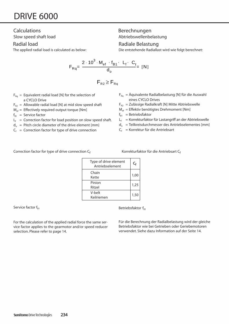
223344
DRIVE 6000
Calculations BerechnungenSlow speed shaft load Abtriebswellenbelastung
Radial loadThe applied radial load is calculated as below:
FRq
2 103 Mef fB1 Lf C. . .f⋅ ⋅
do---------------------------------------------------------------------- N[ ]==
FR2 FRq≥
FRq = Equivalent radial load [N] for the selection of a CYCLO Drive
FR2 = Allowable radial load [N] at mid slow speed shaftMef = Effectively required output torque [Nm]fB1 = Service factorLf = Correction factor for load position on slow speed shaft.do = Pitch circle diameter of the drive element [mm]Cf = Correction factor for type of drive connection
Correction factor for type of drive connection Cf Korrekturfaktor für die Antriebsart Cf
Service factor fB1
For the calculation of the applied radial force the same ser-vice factor applies to the gearmotor and/or speed reducerselection. Please refer to page 14.
Radiale BelastungDie entstehende Radiallast wird wie folgt berechnet:
FRq = Äquivalente Radialbelastung [N] für die Auswahl eines CYCLO Drives
FR2 = Zulässige Radialkraft [N] Mitte AbtriebswelleMef = Effektiv benötigtes Drehmoment [Nm]fB1 = BetriebsfaktorLf = Korrekturfaktor für Lastangriff an der Abtriebswelledo = Teilkreisdurchmesser des Antriebselementes [mm]Cf = Korrektur für die Antriebsart
Type of drive elementAntriebselement
CCff
ChainKette
PinionRitzel
V-beltKeilriemen
1,00
1,25
1,50
Für die Berechnung der Radialbelastung wird der gleicheBetriebsfaktor wie bei Getrieben oder Geriebemotorenverwendet. Siehe dazu Information auf der Seite 14.
Betriebsfaktor fB1

SSiizzee
GGrröößßee 55 1100 1155 2200 2255 3300 3355 4400 4455 5500 6600 7700 8800 9900 110000 112200 114400 116600 118800 220000 222255 225500 227755 330000
606E 0,83 0,94 1,19 1,56 1,74 1,98606G 0,83 0,94 1,19 1,56607E 0,82 0,91 1,00 1,29 1,59 1,88 2,00 2,23607G 0,82 0,91 1,00 1,29 1,59 1,88608E 0,81 0,87 0,94 1,03 1,28 1,54 1,80 1,85 2,00 2,19608G 0,81 0,87 0,94 1,03 1,28 1,54 1,80609E 0,86 0,92 0,97 1,13 1,38 1,64 1,90 1,98 2,15 2,32609G 0,86 0,92 0,97 1,13 1,38 1,64 1,90610E 0,86 0,92 0,97 1,13 1,38 1,64 1,90 1,98 2,15 2,32 2,68610G 0,86 0,92 0,97 1,13 1,38 1,64 1,90611E 0,78 0,84 0,90 0,96 1,02 1,08 1,19 1,36 1,53 1,65 1,71 2,00611G 0,78 0,84 0,90 0,96 1,02 1,08 1,19 1,36 1,53612E 0,82 0,87 0,92 0,97 1,08 1,25 1,42 1,59 1,76 1,90 2,15612G 0,82 0,87 0,92 0,97 1,08 1,25 1,42 1,59 1,76613E 0,83 0,87 0,92 0,96 1,00 1,13 1,25 1,38 1,63 1,88 1,95 2,19 2,67613G 0,83 0,87 0,92 0,96 1,00 1,13 1,25 1,38 1,63 1,88614E 0,66 0,73 0,80 0,87 0,93 1,00 1,10 1,30 1,50 1,70 1,90 2,05614G 0,66 0,73 0,80 0,87 0,93 1,00 1,10 1,30 1,50 1,70 1,90616 0,83 0,87 0,90 0,93 0,97 1,00 1,11 1,32 1,53 1,75 1,96617 0,86 0,89 0,92 0,94 0,97 1,00 1,11 1,32 1,53 1,75 1,96618 0,85 0,87 0,90 0,93 0,95 0,98 1,09 1,26 1,43 1,60 1,78619 0,85 0,87 0,89 0,91 0,93 0,97 1,04 1,18 1,32 1,46 1,75620 0,70 0,74 0,77 0,84 0,91 0,98 1,05 1,12 1,26 1,40 1,54621 0,70 0,73 0,77 0,84 0,91 0,98 1,05 1,13 1,27 1,41 1,56622 0,86 0,88 0,90 0,93 0,96 0,99 1,02 1,06 1,12 1,19 1,25623 0,82 0,84 0,85 0,88 0,91 0,94 0,97 1,00 1,06 1,12 1,18 1,24 1,30624 0,83 0,84 0,86 0,89 0,92 0,94 0,97 1,00 1,06 1,11 1,17 1,23 1,29625 0,83 0,85 0,88 0,90 0,93 0,95 1,00 1,05 1,10 1,22 1,36 1,52 1,69626 0,83 0,85 0,88 0,90 0,94 0,98 1,04 1,17 1,29 1,45 1,61 1,77 1,93627 0,67 0,71 0,75 0,82 0,90 0,98 1,09 1,21 1,35 1,50 1,65 1,79
[mm]
Correction factor Lf for load position
223355
DRIVE 6000
Calculations BerechnungenSlow speed shaft load Abtriebswellenlast
Korrekturfaktor Lf für Lastangriff
Cal
cula
tions
Bere
chnu
ngen

Allowable radial load FR2[N] (Cf, Lf, fB = 1.0)
11.. ““RR11””--ssppeeeedd rreedduucceerr with high capacity bearing
nn 22
[[rrppmm]]
661133 661166 661177 661188 661199
1234568
1015 29500 41700 5900020 14700 29500 41700 5900025 14700 22100 29500 41700 5900030 14700 22100 29500 41700 5900035 14700 22100 29500 41700 5900040 14700 22100 29500 41700 5900050 14700 22100 29500 41700 5520060 14700 22100 29500 41700 5300080 14100 22100 29500 41300 47200
100 13500 21600 29300 38600 44000125 12600 20100 27400 36200 41000150 11900 19000 25900 34200 38300200 10900 17500 23800 31400 34700250 10200 16300 22200300 9660 15400 21100
SSiizzee // GGrröößßee
nn 22
[[rrppmm]]
661133 661166 661177 661188 661199 662200 662211 662222 662233 662244 662255 662266 662277
1 24000 33600 45900 55700 71800 97800 132000 161000 183000 223000 274000 283000 2720002 24000 33600 45900 55700 71800 97800 132000 161000 183000 223000 274000 283000 2720003 24000 33600 45900 55700 71800 97800 132000 161000 183000 223000 274000 283000 2720004 24000 33600 45900 55700 71800 97800 132000 161000 183000 223000 274000 283000 2720005 24000 33600 45900 55700 71800 97800 126000 156000 183000 209000 258000 283000 2720006 24000 33600 45900 55700 71800 97800 119000 148000 183000 198000 244000 283000 2720008 24000 33600 45900 55700 71800 97800 109000 135000 170000 181000 224000 270000 272000
10 24000 33600 45900 55700 71800 97800 126000 159000 169000 210000 253000 27200015 23800 33600 45900 55700 71800 89100 112000 141000 150000 185000 224000 27200020 21800 33600 45900 55700 71800 84100 103000 129000 138000 170000 205000 27200025 20400 33600 45300 55700 71800 96300 121000 129000 159000 191000 27200030 19300 31500 42900 55700 69300 91100 114000 122000 151000 181000 27200035 18400 30100 40900 54000 66100 87000 109000 116000 144000 17400040 17800 28900 39300 51900 63500 83500 105000 112000 139000 16600050 16500 27000 36800 48500 59400 78100 98100 105000 129000 15600060 15600 25600 34800 45900 56300 74000 92900 98900 123000 14800080 14400 23500 31900 42100 51600 67900 85300 90800 112000 135000
100 13500 22000 29900 39400 48300 63500125 12600 20500 27900 36900 45100 59400150 11900 19400 26400 34900 42800200 10900 17900 24300 32000 39300250 10200 16600 22200300 9660 15400 21100
SSiizzee // GGrröößßee
22.. ““RR22””--ssppeeeedd rreedduucceerr with high capacity bearing and ductile iron casing
* for Size 6145 ‘R1’ is standard * bei Größe 6145 ist ‘R1’ Standard
223366
DRIVE 6000
Calculations BerechnungenSlow speed shaft load Abtriebswellenlast
22.. ““RR22””--GGeettrriieebbee mit verstärkter Lagerung und Sphärogussgehäuse
Zul. Radiallast FR2[N] (Cf, Lf, fB = 1.0)
11.. ““RR11””--GGeettrriieebbee mit verstärkter Lagerung

Zulässige Axialbelastung FA2[N] (FR2 = 0)Allowable axial load FA2[N] (FR2 = 0)
nn 22
[[rrppmm]]
660066 660077 660088 660099 661100 661111 661122 661133 661144
10 294 785 981 981 1470 1470 2940 3920 540015 294 785 981 981 1470 1470 2940 3920 540020 294 785 981 981 1470 1470 2940 3920 540025 294 785 981 981 1470 1470 2940 3920 540030 294 785 981 981 1470 1470 2940 3920 540035 294 785 981 981 1470 1470 2940 3920 540040 294 785 981 981 1470 1470 2940 3920 540050 294 785 981 981 1470 1470 2940 3920 540060 294 785 981 981 1470 1470 2940 3920 540080 294 785 981 981 1470 1470 2940 3920 5230
100 294 785 981 981 1470 1470 2940 3920 4860125 294 785 981 981 1470 1470 2940 3920 4560150 294 785 981 981 1470 1470 2940 3920 4370200 294 785 981 981 1470 1470 2770 3920 3850250 785 981 981 1470 1470 2500 3920 3670300 785 981 981 1470 1470 2390 3920 3450
SSiizzee // GGrröößßee
nn 22
[[rrppmm]]
661166 661177 661188 661199 662200 662211 662222 662233 662244 662255 662266 662277
10 6870 9810 13700 19600 26500 27500 29400 35300 37300 48100 52000 5890015 6870 9810 13700 19600 23500 24500 25600 31400 33800 43100 52000 5890020 6870 9810 13700 19600 21100 22100 23200 28400 30900 39400 51000 5890025 6870 9810 13700 19600 19600 20600 21700 26500 28800 36900 47500 5890030 6870 9810 13700 19600 18600 19600 20600 25000 27300 35100 44800 5890035 6870 9810 13700 19600 18100 18600 19600 23500 26100 33600 42800 5890040 6870 9810 13700 19600 17700 18100 18700 22600 25100 32300 41600 5890050 6870 9810 13700 19600 16700 17200 17600 21100 23500 30400 38900 5890060 6870 9810 13700 19600 15700 16200 16700 20100 22300 28500 3730080 6870 9810 13700 19600 14200 14700 15300 18600 21000 26800 34800
100 6870 9810 13700 19600 13200 13700 14400 17700 19900 25500 33000125 6870 9680 13100 18500 12800 13200 13600 16700 19100 24200 31100150 6870 9020 12500 17500 12300 12800 13100200 6300 8090 11000 15400 11300 11800 12100250 5700 7330300 6880
SSiizzee // GGrröößßee
223377
DRIVE 6000
Calculations BerechnungenSlow speed shaft axial load Abtriebswellenlast
Cal
cula
tions
Bere
chnu
ngen

Allowable radial load FR1[N]
SSiizzeeGGrröößßee
196 147 196 196 196 19678,5 38471 49,1 49,1 49,1 49,1
609DA 610DA 612DA 3~17, 25~35, 51, 59 196 147 196 196 196613DA 614DA 21, 43 49,1 49,1 49,1 49,1 147
3~15, 21~29, 43~59, 87 196 147 196 196 19617, 35, 71 49,1 49,1 49,1 49,1 147
612DB 613DB 614DB 3~17, 25~71, 119 294 294 294 294 294616DA 617DA 21, 87 196 196 196 245 245
613DC 614DC 616DB 3~11, 17~119 441 540 589 589617DB 618DA 13, 15 343 491 491 540
3, 8, 21~87 441 343 491 491 540 58911~17 196 196 196 245 245 294
616DC 617DC 3~17 590 690 780 880619DA 620DA 21~87 540 440 540 590618DB 619DB 3~17, 21 1370 1370 1520 1620 1720 1860
620DA 621DA 622DA 25~87 1280 1280 1370 1470 1570 17703, 8 1370 1370 1520 1620 1720 1860
11~21 1230 980 1180 1230 132025 1080 1130 1280 1320 1370
29~87 540 590 690 690 690 10803~25, 51, 59 1770 1770 2060 2160 2160 2160
29~43, 71, 87 1080 1180 1370 1370 1570 1770617 622DB 625DA 3~87 2060 2060 2260 2350 2450 2650618 623DB 624DB 11~87 2750 2550 2940 3040 3340 3430
11~25 3040 3040 3530 3630 3920 393029~87 2650 2550 2940 3140 3340 3630
620 11~87 5400 4910 5890 6080 6230 6180621 11~87 5740 5100 6130 6330 6820 7260622 11~87 6620 5790 6130 6620 6970 7500623 11~87 9520 9170 8980 8730624 11~87 10100 10100 10600 11200625 11~87 10800 11300 12300 13100626 11~87 10800 11300 12300 13100627 29~87 14700 14700 14700 14700
619
RRaattiiooÜÜbbeerrsseettzzuunngg
614
616 621DB 623DA 624DA
606 606DA 607DA
625DB 626DA 627DA
610
612
22990000
607
608
609
3 ~ 17, 25~3521, 43
613
589
880
196
441
880
1470
611
998800 887700 772200 55880011445500
196
294
223388
DRIVE 6000
Calculations BerechnungenHigh speed shaft load Antriebswellenlast
Zulässige Radiallast FR1[N]

SSiizzee
GGrröößßee 55 1100 1155 2200 2255 3300 3355 4400 4455 5500 6600 7700 8800 9900 110000 112200 114400 116600 118800 220000
609DA 610DA
612DA 613DA 0,73 0,9 1,2 1,6 2
614DA
608 0,73 0,9 1,2 1,6 2
612DB 613DB
614DB 616DA 0,88 1 1,2 1,6 2 2,4
617DA
613DC 614DC
616DB 617DB 0,88 1 1,2 1,6 2 2,4
618DA
611 0,88 1 1,2 1,6 2 2,4
616DC 617DC
619DA 620DA
618DB 619DB
620DA 621DA 0,8 0,9 1 1,2 1,5 1,7 1,9 2,1
622DA
614 0,8 0,9 1 1,2 1,5 1,7 1,9 2,1
621DB 623DA
624DA
617 622DB 625DA 0,9 1 1 1,1 1,2 1,3 1,4 1,5 1,7 1,9 2,2
618 623DB 624DB 0,9 1 1 1,1 1,2 1,3 1,4 1,6 1,8 2 2,2
625DB 626DA
627DA
620 0,9 1 1 1 1 1,1 1,2 1,3 1,5 1,6 1,7 1,9
621 0,9 1 1 1 1 1,1 1,2 1,3 1,4 1,5 1,6 1,8
622 0,9 1 1 1 1 1 1,1 1,1 1,2 1,3 1,4 1,6
623 0,8 0,9 0,9 0,9 0,9 1 1,1 1,2 1,3 1,3 1,4 1,6
624 0,9 0,9 0,9 1 1 1 1,1 1,2 1,2 1,3 1,4 1,6
625 0,9 0,9 0,9 1 1 1 1,1 1,2 1,2 1,3 1,5 1,6 1,7
626 0,9 0,9 0,9 1 1 1 1,1 1,2 1,2 1,3 1,5 1,6 1,7
627 0,9 0,9 1 1 1 1,1 1,2 1,4 1,6 1,7 1,9 2,1
1 1,1
609
610
613
612
619
0,9 1
0,73606606DA 607DA
607
0,9 1,2 1,6
616
0,8 0,9 1,1 1,4 1,7 2 2,2
2
1,2 1,3 1,4 1,5 1,6 1,9
0,9 1 1 1 1,1 1,2 1,3 1,4 1,6 1,8 1,9 2,1
[[mmmm]]
Correction factor Lf for load position
223399
DRIVE 6000
Calculations BerechnungenHigh speed shaft load Antriebswellenlast
Korrekturfaktor Lf für Lastangriff
Cal
cula
tions
Bere
chnu
ngen

JJGG [10-4 kgm2]
66 88 1111 1133 1155 1177 2211 2255 2299 3355 4433 5511 5599 7711 8877 111199
6205G 237 216 204 196 190 188 186 626215G 373 340 323 310 300 298 295 1056225G 483 437 410 388 375 370 368 1506235G 810 740 695 665 645 638 633 2606245G 1240 1130 1160 1010 983 970 963 5936255G 2230 2040 1920 1840 1800 1780 1770 5936265G 2930 2650 2490 2370 2300 2260 22506275G 7480 7400 7350
SSiizzee
133 20,90131 130 129 128 127 127152 148 140 137169 159
51,50 50,50 50,00 8,1849,80 49,50
36,50
73 67,80 61,80 59,80 57,00 54,30 52,80 52,30
17,60 17,60 17,60
62,00 51,00 47,80 43,80 37,80 37,00 36,80
19,30 18,90 18,10 17,9023,20 22,20 21,20 19,90
2,55 2,50 2,482,80 2,73 2,58 2,55
2,48
10,40 7,24 5,30 4,33 3,95 3,63 3,15 3,00
2,58 2,55 2,55 2,493,15 4,73 2,80 2,734,96 4,30 3,95 3,65
1,14 0,77 1,111,26 1,22 1,18 0,80
0,58
3,45 2,17 1,91 1,36 1,27 1,56 1,04 0,94
0,61 0,59 0,59 0,590,67 0,66 0,64 0,620,91 0,83 0,78 0,75
0,19 0,13 0,19 0,130,23 0,21 0,21 0,140,26 0,30 0,20 0,170,84 0,50 0,40 0,29
0,18 0,24 0,18 0,24
0,35
0,33 0,39 0,311,02 0,68 0,65 0,56
0,31 0,29 0,28 0,27 0,20
0,55 0,59 0,35 0,31 0,18
ffaannLLüüfftteerr
[[mmmm]]
0,12 0,12 0,12 0,110,19 0,19 0,18 0,12
0,11 0,11 0,11 0,110,12 0,12 0,120,14 0,13 0,13 0,12
1,57
78,80
0,16
1,18
9,24 6,52
36,50 29,00
0,43
6170G6175G6180G6185G6190G6195G
0,13
6070E6075E6080E6085E6090E6095E
6140E6145E6160G6165G
0,20
0,196060E6065E
0,16 0,14 0,13
6100E6115E6110E6115E6120E6125E6130E6135E
0,12 0,12 0,12 0,12
42,50 40,30 39,50 38,30
0,11 0,11
17,30 17,30
36,50 36,30
8,85
8,33
referred to the high speed shaft
224400
DRIVE 6000
Calculations BerechnungenInertia speed reducer (JG ) Trägheitsmoment des Getriebes (JG )
bezogen auf die Antriebswelle
Notes:The value of the fan has been added to the inertia ofthe reducer for Sizes 6160 - 6275The inertia of a double stage unit is calculated by theformulaJ = JG1 + JG2/i1
2
JG1 = inertia of first (input) stageJG2 = inertia of second (output) stage; reduce the value
of the inertia from above tablei1 = ratio of the first stage
Anm.: Der Wert des Lüfters ist addiert zum Trägheitsmomentdes Getriebes für die Größen 6160 - 6275.Das Trägheitsmoment des zweistufigen Getriebes istnach folgender Formel zu errechnen:J = JG1 + JG2/i1
2
JG1 = Trägheitsmoment der 1. Stufe (Antrieb) aus obiger Tabelle
JG2 = Trägheitsmoment der 2. Stufe (Abtrieb) minus Trägheitsmoment aus obiger Tabelle
i1 = Übersetzung der 1. Stufe

66 88 1111 1133 1155 1177 2211 2255 2299 3355 4433 5511 5599 7711 8877 111199
6205G 162 141 129 121 115 113 1176215G 248 216 197 184 175 172 1706225G 305 258 232 210 197 192 1886235G 498 428 383 353 335 325 3236245G 903 793 723 680 650 638 6336255G 1470 1280 1160 1080 1040 1020 10006265G 2150 1870 1700 1580 1510 1480 14606275G 4900 4730 4650 4600
SSiizzee
0,178
5,53 5,45
23,8 23,7
34,5
0,192 0,128
1,85
34,3
0,239
30 28 27 25,5
0,089 0,0880,099 0,095 0,092 0,09
0,166 0,163
0,58
1,29 0,908
2,35
101
0,1686060E6065E
0,133 0,112
6100E6115E6110E6115E6120E6125E
1,51
6130E6135E
6170G6175G6180G6185G6190G6195G
6140E6145E6160G6165G
0,102
6070E6075E6080E6085E6090E6095E
0,172 0,107 0,102
0,623 0,605
0,106
66
0,135 0,114
0,955 0,74 0,593
9,44 6,41 4,55
0,1 0,095 0,092 0,091 0,089 0,088 0,087 0,087
0,093 0,093 0,091 0,091
[[mmmm]]
0,405 0,331 0,281 0,268 0,255 0,249 0,172 0,158 0,095
0,53 0,403 0,39 0,325 0,253 0,248 0,242 0,181 0,236
0,774 0,558 0,342 0,35 0,32 0,224 0,258 0,236 0,163 0,152 0,143 0,198 0,132 0,188
1,12 0,849 0,768 0,72 0,688 0,61 0,595 0,558 0,548 0,533 0,53 0,525 0,523
3,1 2,53 1,56 1,71 1,62 1,21 1,39 0,865 0,825 1,15 0,788 1,12 0,76
8,62 5,9 4,34 3,68 3,3 3,03 2,51 2,16 2,08 1,96 1,93 1,91 1,86
3,68 3,33 2,95 2,52 2,35 2,16 2,09 1,96 1,91 1,91 1,86 1,85
24,7 17,2 12,4 11 6,1 5,58 5,759,9 8,35 7,65 7,15 5,78
49,3 38,8 35,3 31,3 25,3 24,5 24,2 23,9
6,35
58,5 52 46,8 44,5 42,3 39,3 37,5 37 36 35 34,5
136 126 120 115 107 104 98,3 96,8 95,8 95 94,5 94
referred to high speed shaft
JJGG [10-4 kgm2]JJ == JJGG ++ JJMM
224411
DRIVE 6000
Calculations BerechnungenInertia Gearmotor Trägheitsmoment des Getriebemotors
bezogen auf die Antriebswelle
Notes:The values in above table do not include inertia ofthe motor.Obtain the inertia of a single stage gearmotor byadding the motor inertia from tables for the motor.The inertia of a double stage unit is calculated bythe formula
J = JG1 + JG2/i12
JG1 = inertia of first (input) stageJG2 = inertia of second (output) stage from reducer
inertia; reduce the value of the inertia fromabove table
i1 = ratio of the first stage
Anm.: Die Werte in o.g. Tabelle schließen nicht dasTrägheitsmoment des Motors ein.Um das Trägheitsmoment eines einstufigenGetriebemotors zu erhalten, bitte dasTrägheitsmoment des Motors aus der Tabelle fürMotoren addieren.Das Trägheitsmoment eines zweistufigen Getriebe-motors ist nach folgender Formel zu errechnen:J = JG1 + JG2/i1
2
JG1 = Trägheitsmoment der 1. Stufe (Antrieb) aus obiger Tabelle
JG2 = Trägheitsmoment der 2. Stufe (Abtrieb) aus Trägheitsmoment des Getriebes, minus Trägheitsmoment aus obiger Tabelle.
i1 = Übersetzung der 1. Stufe
Cal
cula
tions
Bere
chnu
ngen

224422
DRIVE 6000

224433
DRIVE 6000
Mot
or-In
form
atio
n
MMoottoorr iinnffoorrmmaattiioonn MMoottoorr--IInnffoorrmmaattiioonn

DRIVE 6000
Motors directly mounted to the CYCLO
GGeenneerraall IInnffoorrmmaattiioonnThe gearmotor are supplied with directly fitted threephase current squirrel cage motors accordingEN 60034. IEC 34-1 as described in the selection list.
Upon request we can supply the gearmotor with bra-kes.
For pole changing motors please consult SumitomoDrive Technologies.
VVeerryy ccoommppaacctt ssiizzeeWith the adoption of a unique high precisiondesign, a series of very small electrical motors forindustrial application was successfully developed forcoupling with the CYCLO Drive.
LLooww iinneerrttiiaaThe compact design of the motor allow for low iner-tia. This makes this motor an ideal match for the lowinertia CYCLO speed reducers.
EExxcceelllleenntt hheeaatt ddiissssiippaattiioonnThe motor casing made of aluminium provides agood heat dissipation.
Due to the high quality coil isolation the gearmotorsare suited for the operation with static frequencyinverter.
224444
Motor information Motor-InformationGeneral Information Allgemeine Information
Motor auf CYCLO Getriebe montiert
AAllllggeemmeeiinnee IInnffoorrmmaattiioonnDie Getriebemotoren werden mit direkt angebautenAsynchron-Kurzschlussläufer-Motoren EN 60034, IEC 34-1gemäß Auswahlliste geliefert.
Auf Anfrage liefern wir die Getriebemotoren mit Bremse.
Für polumschaltbare Motoren bitte Rücksprache mitSumitomo Drive Technologies.
ÄÄuußßeerrsstt kkoommppaakkttee BBaauuffoorrmmDurch die Optimierung des Motorkonzeptes wurde eineSerie äußerst kompakter Elektromotoren für den indus-triellen Einsatz entwickelt und für den Direktanbau anCYCLO Drive angepasst.
GGeerriinnggeess TTrräägghheeiittssmmoommeennttDie kompakte Motorbauform bietet ein geringesTrägheitsmoment. Dadurch sind die Motoren ideal zumAnbau an CYCLO Getriebe geeignet, die sich ebenfallsdurch ein geringes Trägheitsmoment auszeichnen.
AAuussggeezzeeiicchhnneettee WWäärrmmeeaabblleeiittuunnggDas Motorgehäuse aus Alu zeichnet sich durch guteWärmeableitung aus.
Die hochwertige Wicklungsisolation erlaubt den Betriebam statischen Frequenzumrichter.

EEnneerrggyy ssaavviinngg mmoottoorrss
Sumitomo's 4-pole AC motors from 1,1 kW to 55 kW fulfilthe requirements of the efficiency class EFF2.EFF1 are available on request.
SSttaannddaarrddss aanndd RReegguullaattiioonnssThe CYCLO gearmotor comply with the followingstandards and regulations
EN60034- 1, IEC 34-1General requirements for rotating electrical machines
EN60034- 6, IEC 34-6Methods of cooling rotating electrical machines
EN60034- 7, IEC 34-7Types of construction of rotating electrical machines
EN60034- 14, IEC 34-14Mechanical vibrations of rotating electrical machines
EN 60 034-5; IEC 60 034-5Degrees of protection by enclosures for rotatingelectrical machinery
IEC60034- 8Terminal designations and direction of rotation ofelectrical machines
OOtthheerr SSttaannddaarrddss aanndd RReegguullaattiioonnssUpon request we can supply gearmotor whichcomply with any other national or internationalstandard.-NEMA/USA-JIS, JEM, JEC/Japan-BS/Great Britain-UL/CSAFor further details please contact Sumitomo DriveTechnologies
224455
DRIVE 6000
Mot
or-In
form
atio
n
Motor information Motor-InformationGeneral Information Allgemeine Information
EEnneerrggiieessppaarreennddee MMoottoorreenn
Die 4-poligen Sumitomo Drehstrommotoren von 1,1kWbis 55kW erfüllen die Anforderungen derWirkungsgradklasse EFF2.EFF1 Motoren sind auf Anfrage erhältlich.
NNoorrmmeenn uunndd VVoorrsscchhrriifftteennDie CYCLO Getriebemotoren entsprechen folgendenNormen und Vorschriften:
EN60034- 1, IEC 34-1Allgemeine Bestimmungen für umlaufende, elektrischeMaschinen.
EN60034- 6, IEC 34-6Kühlarten umlaufender elektrischer Maschinen.
EN60034- 7, IEC 34-7Bauformen umlaufender elektrischer Maschinen.
EN60034- 14, IEC 34-14Mechanische Schwingungen von umlaufendenelektrischen Maschinen.
EN 60 034-5; IEC 60 034-5Schutzarten umlaufender elektrischer Betriebsmittel.
IEC60034- 8Anschlussbezeichnungen und Drehsinn von umlaufen-den elektrischen Maschinen.
WWeeiitteerree NNoorrmmeenn uunndd VVoorrsscchhrriifftteennAuf Anfrage sind auch Getriebemotoren lieferbarnach folgenden nationalen oder internationalenNormen und Vorschriften:-NEMA/USA-JIS, JEM, JEC/Japan-BS/Great Britain-UL/CSAFür weitere Informationen wenden Sie sich bitte anSumitomo Drive Technologies.

Standard motor SpecificationPM = motor power [kW]
nM = motor speed [min-1]
IN = rated current [A]
cos ϕ = power factorη = efficiency [%]MA/MN = starting torque/rated torque [%]
MK/MN = breakdown torque/rated torque [%]
IA/IN = starting current/rated current [%]
Y / starting possible
0,12 kW - 4kW 5,5 - 55 kW
*) Y / Δ starting possibleStern-/Dreieck-Anlauf möglich
PP MMoottoorr nn TT IInn AA IInn AA ccooss ϕϕ EEFFFF22 MMAA//MMNN MMKK//MMNN IIAA//IINN JJMM
kkWW 44ppssiizzee
GGrröößßee 11//mmiinnMM
NNmm
223300 VV5500 HHzz
440000 VV5500 HHzz
440000 VV5500 HHzz
440000 VV 110000%%
5500 HHzz7755%%
%% %% %% 1100 --44 kkgg mm²²
0,12 F 63S 1410 0,8 0,67 0,39 0,70 64,4 62,0 202 213 333 3,250,18 F 63M 1430 1,2 1,00 0,59 0,66 67,5 64,4 262 259 397 5,000,25 F 63M 1390 1,7 1,20 0,70 0,74 70,4 70,0 222 202 368 5,000,37 F 71M 1420 2,5 2,00 1,20 0,66 69,0 67,2 246 232 379 6,500,55 F 80S 1420 3,7 2,40 1,40 0,77 74,5 74,9 225 200 399 10,10,75 F 80M 1430 5,0 3,30 1,90 0,76 74,3 73,8 212 217 417 12,01,1 F 90S 1420 7,4 4,60 2,70 0,77 EFF2 78,2 78,1 223 236 500 18,51,5 F 90L 1430 10 6,00 3,50 0,79 EFF2 78,6 78,5 212 226 476 21,32,2 F 100L 1430 15 8,30 4,80 0,79 EFF2 82,8 83,5 255 231 537 33,33 F 112S 1420 20 11,10 6,40 0,82 EFF2 82,9 83,4 237 224 579 70,04 F 112M 1420 27 14,10 8,20 0,84 EFF2 84,4 85,7 219 223 575 84,8
5,5 F 132S 1420 37 11,1 0,84 EFF2 85,6 86,5 256 237 658 1147,5 F 132M 1450 49 14,8 0,83 EFF2 88,1 88,1 260 317 669 26811 F 160M 1450 72 21,0 0,85 EFF2 89,2 89,3 282 326 697 37515 G 160L 1470 97 26,6 0,88 EFF2 92,4 92,7 265 271 677 898
18,5 F 180MG 1450 122 33,1 0,88 EFF2 91,7 91,8 312 293 789 2.25022 F 180MG 1440 146 39,3 0,89 EFF2 90,5 91,3 262 246 659 2.25030 F 180L 1450 197 54 0,87 EFF2 91,8 92,4 265 244 635 2.50037 F 200L 1460 242 66 0,87 EFF2 92,8 93,1 287 256 675 3.07545 F 200L 1450 297 81 0,87 EFF2 92,7 93,3 288 252 665 3.42555 F 225S 1460 360 96 0,89 EFF2 93,0 93,3 234 252 658 6.750
6-pole18,5 F 180L 980 180 36,0 0,81 91,9 91,9 274 312 694 3.62522 F 180L 970 217 41,9 0,83 91,5 92,0 230 261 597 3.62530 F 200L 960 299 56 0,85 90,8 91,6 267 269 620 4.75037 F 200L 970 364 69 0,84 92,2 92,6 293 289 664 6.00045 F 225S 970 443 82 0,86 92,2 92,9 244 238 584 10.00055 F 250S 970 542 100 0,87 92,2 93,1 242 231 576 11.750
224466
DRIVE 6000
Motor information Motor-Information
Standard Motor SpezifikationPM = Motorleistung [kW]
nM = Motordrehzahl [min-1]
IN = Nennstrom [A]
cos ϕ = Leistungsfaktorη = Wirkungsgrad [%]MA/MN = Anzugsmoment/Nennmoment [%]
MK/MN = Kippmoment/Nennmoment [%]
IA/IN = Anzugsstrom/Nennstrom [%]

PPMM mmoottoorr nnMM IInn pp..ff..
kkWW 44pp ffrraammee 11//mmiinn AA ccooss ϕϕ223300 VV6600 HHzz
446600VV6600 HHzz
0,12 F 63S 1.720 0,35 0,65 0,1 0,040,18 F 63M 1.740 0,54 0,61 0,1 0,060,25 F 63M 1.710 0,62 0,70 0,1 0,060,37 F 71M 1.750 1,00 0,63 0,1 0,060,55 F 80S 1.730 1,20 0,73 0,1 0,10,75 F 80M 1.750 1,70 0,72 0,1 0,11,1 F 90S 1.730 2,30 0,74 0,3 0,21,5 F 90L 1.740 3,00 0,76 0,3 0,22,2 F 100L 1.730 4,20 0,77 0,3 0,23 F 112S 1.730 5,30 0,84 0,6 0,34 F 112M 1.720 7,00 0,84 0,6 0,3
5,5 F 132S 1.730 9,40 0,84 0,37,5 F 132M 1.760 12,6 0,84 0,511 F 160M 1.760 17,9 0,85 0,515 G 160L 1.770 23,1 0,89 0,5
18,5 F 180MG 1.750 28,6 0,89 0,522 F 180MG 1.740 33,7 0,90 0,530 F 180L 1.750 46,3 0,88 0,537 F 200L 1.740 57,0 0,88 1,2745 F 200L 1.740 69,0 0,88 1,2755 F 225S 1.750 83,0 0,90 1,27
6-pole18,5 F 180L 1.180 30,8 0,82 ---22 F 180L 1.170 35,6 0,84 ---30 F 200L 1.180 47,6 0,85 ---37 F 200L 1.170 59,0 0,85 ---45 F 225S 1.170 70,0 0,87 ---55 F 250S 1.160 85,0 0,87 ---
BBrraakkee ccuurrrreenntt AA
224477
DRIVE 6000
Mot
or-In
form
atio
n
Motor information Motor-InformationApplication Applikationen
Range of application:
Voltage and frequency:The CYCLO gearmotor is suitable forthe connection to the following IEC standard voltages.According to DIN EN 60034-1.
0,12 kW - 4.0 kW50 Hz : 220-240V Δ / 380 - 420V Y +/- 5 %
Usage with 60 Hz allowable for 440 to 480V
5,5 kW - 55 kW50 Hz : 380 - 420V Δ +/- 5%
Standard motor data for 440 - 480V 60Hz Standard Motor Daten für 440 - 480V 60Hz
Einsatzbereich:
Spannungsbereich und Frequenz:Die CYCLO Getriebemotoren sind für den Anschluss anfolgende IEC Normspannungen geeignet.Nach DIN EN 60034-1.
0,12 kW - 4,0 kW50 Hz : 220-240V Δ / 380 - 420V Y +/- 5 %
Der Betrieb an 60 Hz ist von 440-480V möglich
5,5 kW - 55 kW50 Hz : 380 - 420V Δ +/- 5%

ER433WW-7
3 PHASE INDUCTION MOTOR
TYPE F90S/4 1.1 kWV 220 - 240 Δ 380 - 420 Y 440 - 460 Y
Hz 50 50 60
A 4.6 2.7 2.3
1/min 1420 1420 1730
P.F.(cos ϕ) 0.77 0.77 0.74
IP 55 INS. CLASS F S1-CONT 40°C IEC 34-1
SERIAL NO. DATE
ER433WW-12
3 PHASE INDUCTION MOTOR
TYPE F132S/4 5.5 kWV 380 - 420 Δ 440 - 460 Δ
Hz 50 60
A 11.1 9.4
1/min 1420 1730
P.F.(cos ϕ) 0.84 0.84
IP 55 INS. CLASS F S1-CONT 40°C IEC 34-1
SERIAL NO. DATE
ER434WW-7
3 PHASE INDUCTION MOTOR
TYPE F90S/4 1.1 kW
V 220 - 240 Δ 380 - 420 Y 440 - 460 Y
Hz 50 50 60
A 4.6 2.7 2.3
1/min 1420 1420 1730
P.F.(cos ) 0.77 0.77 0.74IP 55 INS. CLASS F S1-CONT 40°C IEC 34-1
SERIAL NO. DATEBrake FB-2B 220-240 VAC 0.3A 15Nm IP44
ϕ
ER434WW-12
3 PHASE INDUCTION MOTOR
TYPE F132S/4 5.5 kW
V 380 - 420 Δ 440 - 460 Δ
Hz 50 60
A 2.7 2.3
1/min 1420 1730
P.F.(cosϕ) 0.77 0.74IP 55 INS. CLASS F S1-CONT 40°C IEC 34-1
SERIAL NO. DATEBrake FB-8B 380-460 VAC 0.3A 55Nm IP44
TToolleerraanncceess ttoo eelleeccttrriiccaall vvaalluueess::
Voltage (area A) ± 5% Spannungsbereich (Bereich A)
Frequency (area A) ± 2% Frequenz (Bereich A)
Efficiency - 0,15 (1-η) Wirkungsgrad
Power factor (cos ϕ) - (1-cos ϕ) / 6 Leistungsfaktor (cos ϕ)
SlipPn < 1 kW ± 30%
SchlupfPn ³ 1 kW ± 20%
Starting current + 20% Anlaufstrom
Starting torque - 15% - + 20% Anzugsmoment
Brake down torque - 10% Kippmoment
Inertia ± 10% Trägheitsmoment
224488
DRIVE 6000
Motor information Motor-InformationName plates (example) Typenschilder (Beispiele)
According to DIN EN 60 034 the following tolerances arepermitted:
Nach DIN EN 60 034 sind folgende Toleranzen zulässig:
TToolleerraannzzeenn zzuu eelleekkttrriisscchheenn AAnnggaabbeenn::

224499
DRIVE 6000
Mot
or-In
form
atio
n
Motor information Motor-InformationBrake Voltage of Sumitomo Standard Motors Bremsenspannung bei Sumitomo Standard Motoren
The motor will be run at 400V.The rectifier is pre connected to the terminal block.The connection bars at the terminal block have to be fixedby the customer acc. to the supply voltage.Here 400V Y-connection. The voltage between L1/U1 andthe so called "star-point" is 230V.The rectifier for the brake is automatically supplied with230V.400V brake is not necessary.
Der Motor wird an 400V betrieben.Der Gleichrichter ist standardmäßig ans Klemmbrett ange-schlossen.Die Brücken am Klemmbrett müssen vom Kunden je nachSpannung eingelegt werden. Hier Y-Schaltung.Die Spannung zwischen L1/U1 und dem so genannten"Sternpunkt" ist 230V.Der Gleichrichter für die Bremse bekommt hier automa-tisch 230V vom Klemmbrett.Eine 400V Bremse ist nicht erforderlich.
0,12 - 4,0 kW
Y380400415 B
rake
Bre
mse
U1 V1 W1
W2 U2 V2
400V 400VL1 L2 L3
230V
GleichrichterRectifier
1 2 3 4
0,12 - 4,0 kW
Y380400415 B
rake
Bre
mse
U1 V1 W1
W2 U2 V2
400V 400VL1 L2 L3
230V
GleichrichterRectifier
1 2 3 4
GleichrichterRectifier
1 2 3 4
400V brake is available as option.The brake will be supplied separately with 400V AC.The 24V DC brake is also supplied separately.
Motor voltage 400V 50Hz, connection YStandard brake control voltage is 230V
Motorspannung 400 V 50 Hz Schaltung YStandard Bremssteuerspannung ist 230V
Eine 400V Bremse ist optional verfügbar. Diese wirdseparat mit 400V versorgt.Auch die 24V DC Bremse wird separat angesteuert.
0,12 - 4,0 kW
Y380400415
U1 V1 W1
W2 U2 V2
400V 400VL1 L2 L3
Bra
keB
rem
se
GleichrichterRectifier
1 2 3 4
400V / 24V
0,12 - 4,0 kW
Y380400415
U1 V1 W1
W2 U2 V2
400V 400VL1 L2 L3
Bra
keB
rem
se
GleichrichterRectifier
1 2 3 4
GleichrichterRectifier
1 2 3 4
400V / 24V
00,,1122 -- 44,,00 kkWW

225500
DRIVE 6000
Motor information Motor-InformationBrake Voltage of Sumitomo Standard Motors Bremsenspannung bei Sumitomo Standard Motoren
Motor voltage 230V 50Hz, connection ΔStandard brake control voltage is 230V
Motorspannung 230 V 50 Hz Schaltung ΔStandard Bremssteuerspannung ist 230V
0,12 - 4,0 kW
Bra
keB
rem
se
U1 V1 W1
W2 U2 V2 Gleichrichter
Rectifier1 2 3 4
Δ
220230240
L1 L2 L3230V 230V
230V
0,12 - 4,0 kW
Bra
keB
rem
se
U1 V1 W1
W2 U2 V2 Gleichrichter
Rectifier1 2 3 4
GleichrichterRectifier
1 2 3 4Δ
220230240
L1 L2 L3230V 230V
230V
00,,1122 -- 44,,00 kkWW
Motor voltage 400V 50 Hz connection ΔStandard brake supply voltage is 400V
Motorspannung 400 V 50 Hz Schaltung ΔStandard Bremssteuerspannung ist 400V
Der Anschluss des Gleichrichters ist unverändert.
Die Brücken sind für 230V eingelegt.
Der Gleichrichter für die Bremse bekommt automa-tisch 230V vom Klemmbrett.
The connection of the rectifier is the same as above.
The connection bars are must be fixed for 230V.
The rectifier for the brake is automatically suppliedwith 230V
55,,55 kkWW -- 1155 kkWW
5,5 -
Brak
eBr
emse
U1 V1 W1
W2 U2 V2 Δ380400415
L1 L2 L3400V 400V
400V
GleichrichterRectifier
1 2 3 4
5,5 - 15
Brak
eBr
emse
U1 V1 W1
W2 U2 V2 Δ380400415
L1 L2 L3400V 400V
400V
GleichrichterRectifier
1 2 3 4
GleichrichterRectifier
1 2 3 4
kW
The rectifier for the brake is automatically suppliedwith 400V.
It has to be a 400V brake. For 15 kW the CMB-20brake is available.
If FB-brake is required, alternatively FB-20 is for230V AC only.
Der Gleichrichter für die Bremse bekommt 400Vvom Klemmbrett.
Es muss eine 400V Bremse sein. Die 15 kW CMBBremse ist in 400V verfügbar.
Falls es eine FB- Bremse sein soll, ist alternativ dieFB-20 nur für 230V AC verfügbar.

OOppttiioonn:: 1155 kkWW
FB-20 / FB-30 15 - . . . kW
Bra
keB
rem
seU1 V1 W1
W2 U2 V2 Δ380400415
L1 L2 L3400V 400V
230V
GleichrichterRectifier
1 2 3 4
FB-20 / FB-30 15 - . . . kW
Bra
keB
rem
seU1 V1 W1
W2 U2 V2 Δ380400415
L1 L2 L3400V 400V
230V
GleichrichterRectifier
1 2 3 4
The brake has to be supplied separately with 230V AC. Die Bremse muss separat mit 230V AC angesteuert werden.
225511
DRIVE 6000
Mot
or-In
form
atio
n
Motor information Motor-InformationBrake Voltage of Sumitomo Standard Motors Bremsenspannung bei Sumitomo Standard Motoren
Motor voltage 400V 50 Hz connection ΔBrake supply voltage is 230V
Motorspannung 400 V 50 Hz Schaltung ΔBremssteuerspannung ist 230V
EExxaammppllee:: Wiring for quick brake with varistor BBeeiissppiieell:: Verdrahtung bei Schnellbremsung mit Varistor
0,12 - 4,0 kW
Y380400415
Bra
keB
rem
se400V 400VL1 L2 L3
U1 V1 W1
W2 U2 V2 GleichrichterRectifier
1 2 3 4
SchaltschrankCabinet
0,12 - 4,0 kW
Y380400415
Bra
keB
rem
se400V 400VL1 L2 L3
U1 V1 W1
W2 U2 V2 GleichrichterRectifier
1 2 3 4
SchaltschrankCabinet

225522
DRIVE 6000
Standard brake input voltages: Rectifier Coil voltageStandard Bremsen Eingangsspannung: Gleichrichter Spulenspannung180 - 250 V (+/- 0%) , 50/60 Hz (0,12 - 4,0 kW) Half wave / Einweg (Standard) 90 V DC380 - 460 V (+/- 0%) , 50/60 Hz (5,5 kW and bigger / ab 5,5 kW)
The standard protection level of the brake is IP 44.IP55 is available on request.
Totalbraking
Standard Fast energy 230 V 400 V 400 VNm Nm sec sec 10-4 kg m² 106 J 50 Hz 50 Hz 50 Hz
0,12 x 4 F 63S FB-01A 1 1,3 0,15 - 0,2 0,015 - 0,02 3,5 120 0,1 0,040,18 x 4 F 63M FB-02A 2 2,7 0,15 - 0,2 0,015 - 0,02 5,5 120 0,1 0,050,25 x 4 F 63M FB-02A 2 2,7 0,15 - 0,2 0,015 - 0,02 5,5 120 0,1 0,050,37 x 4 F 71M FB-05A 4 5,4 0,1 - 0,15 0,01 - 0,015 6,75 120 0,1 0,050,55 x 4 F 80S FB-1B 7,5 10 0,2 - 0,3 0,01 - 0,02 11,1 330 0,1 0,10,75 x 4 F 80M FB-1B 7,5 10 0,2 - 0,3 0,01 - 0,02 13 330 0,1 0,11,1 x 4 F 90S FB-2B 15 20 0,2 - 0,3 0,01 - 0,02 20,8 380 0,3 0,11,5 x 4 F 90L FB-2B 15 20 0,2 - 0,3 0,01 - 0,02 23,5 380 0,3 0,12,2 x 4 F 100L FB-3B 22 30 0,3 - 0,4 0,01 - 0,02 37,3 450 0,3 0,13,0 x 4 F 112S FB-5B 37 50 0,4 - 0,5 0,01 - 0,02 81 2350 0,6 0,34,0 x 4 F 112M FB-5B 37 50 0,4 - 0,5 0,01 - 0,02 96 2350 0,6 0,35,5 x 4 F 132S FB-8B 55 74 0,3 - 0,4 0,01 - 0,02 125 2350 - 0,3 -7,5 x 4 F 132M FB-10B 75 100 0,7 - 0,8 0,03 - 0,04 303 3430 - 0,4 -11 x 4 F 160M FB-15B 110 110 0,5 - 0,6 0,03 - 0,04 410 3430 - 0,4 -15 x 4 G 160L CMB-20 100 100 0,4 - 0,5 0,1 - 0,15 1330 3040 - 1,6 -15 x 4 G 160L FB-20 150 220 1,7 - 1,8 0,03 - 0,06 1070 10100 0,6 - -
18,5 x 4 F 180MG FB-30 190 220 1,4 - 1,5 0,03 - 0,06 2430 10100 0,6 - - 22 x 4 F 180MG FB-30 220 220 1,4 - 1,5 0,03 - 0,06 2430 10100 0,6 - - 30 x 4 F 180L FB-30 220 220 1,4 - 1,5 0,03 - 0,06 2620 10100 0,6 - -
Max. brake torque
P1kW
Motor size Brake size
Brake torque
Brake delay timecurrent A
Standard BrakeOptionBrake motor
inertia
Motor information Motor-InformationBrake Motor Data Bremsmotoren Daten
BBrraakkee ttoorrqquuee::The brake motor will be supplied with the standard braketorque. The brake motors can be supplied with theincreased torque on request.
If you require larger or smaller brake torque than thoselisted, please advise the factory when ordering.
CChhaarraacctteerriissttiiccss ooff tthhee FFBB bbrraakkeessLow inertiaLong lifeLow maintenanceEnclosure IP 44 (IP 54, 55 upon request)One touch brake release lever for upon request, forsize: FB-01A - FB-15B
The standard brakemotor used for outdoor installationmust be IP55.For vertical mounting a canopy must be used.The rectifier shown is supplied in the motor terminal box.
Die Standardschutzart der Bremsen ist IP 44.Ausführung IP55 als Option.
Half wave / Einweg (Standard) 180 V DC
BBrreemmssmmoommeenntt::Die Bremsmotoren werden mit dem Standard-Bremsmo-ment geliefert. Die Bremsen können auf Anfrage mit demerhöhten Bremsmoment geliefert werden.
Für Bremsmomente außerhalb dieses Bereiches bitten wirum Rücksprache.
FFBB BBrreemmsseenn -- MMeerrkkmmaalleeGeringes TrägheitsmomentLange LebensdauerGeringe WartungsanforderungenSchutzart IP 44 (IP 54, 55)Hebel für Handlüftung als Option lieferbar für Größe: FB-01A - FB-15B
Für die Aufstellung im Freien muss die Bremse in SchutzartIP 55 ausgeführt sein.Bei Bauform V1 (vertikal) muss ein Schutzdach vorgesehenwerden.Der Gleichrichter ist im Klemmenkasten eingebaut(Standard)
* CMB-20 is StandardFB-20 is special
* CMB-20 ist StandardFB-20 ist Sonder

Mot
or-In
form
atio
n
TTyyppiiccaall bbrraakkeemmoottoorr wwiirriinnggIllustrated below is a typical brakemotor wiring schematic.The rectifier shown is supplied in the motor terminal box.
Brake FB-01A to FB-15B Bremse FB-01A bis FB-15B
Motor information Motor-Information
BBrreemmssmmoottoorr AAnnsscchhlluussssddiiaaggrraammmmDie folgenden Abbildungen zeigen Schaltbilder der Bremsmotoren.Der Gleichrichter ist im Klemmenkasten eingebaut.
Brake CMB-20 Bremse CMB-20
225533
DRIVE 6000

225544
DRIVE 6000
In case of fast brake operation, please protect the externalswitch contact with a varistor acc. to the specificationbelow:
Alternatively the varistor can be placed according to thediagrams below:
VARISTOR Specification
Motor operating voltage 230 V 400 V
Varistor rated voltage AC 260 - 300 V AC 510 V
Varistor voltage 430 470 V 820 V
Varistor rated power
FB-01A, FB-02A, FB-05A < 0,2 WFB-1B > 0,4 WFB-2B. FB-3B, FB-5B, > 0,6 WFB-8B, FB10B, FB-15B > 1,5 W
VARISTOR Spezifikation
Motor Betriebsspannung 230 V 400 V
Varistor Nennspannung AC 260 - 300 V AC 510 V
Varistorspannung 430 470 V 820 V
Varistor Nenn-leistung
FB-01A, FB-02A, FB-05A < 0,2 WFB-1B > 0,4 WFB-2B. FB-3B, FB-5B, > 0,6 WFB-8B, FB10B, FB-15B > 1,5 W
Wenn Sie die Einfallzeit der Bremse beschleunigen, schüt-zen Sie den externen Schaltkontakt mit einem Varistor mitu.a. Spezifikation:
Alternativ kann ein Varistor wie folgt verwendet werden:
Motor information Motor-InformationBrakemotor Bremsmotor
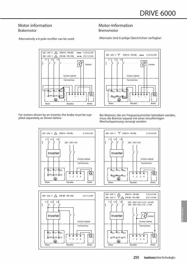
Mot
or-In
form
atio
n
Alternatively a 6-pole rectifier can be used:
For motors driven by an inverter, the brake must be sup-plied separately, as shown below
Alternativ sind 6-polige Gleichrichter verfügbar:
Bei Motoren, die am Frequenzumricher betrieben werden,muss die Bremse separat mit einer sinusförmigenWechselspannung versorgt werden:
Motor information Motor-InformationBrakemotor Bremsmotor
225555
DRIVE 6000

225566
DRIVE 6000
wiring voltage voltage factor factor factor factor break downfor 50 Hz at 60 Hz speed power rated torque starting torque
Faktor Faktor Faktor Faktor Kipp-/Wicklungsspannung Spannung Drehzahl Leistung Nennmoment Anzugsmoment
für 50 Hz bei 60 Hz n60Hz/n50Hz n60Hz/n50Hz MN60Hz/MN50Hz MK60Hz /MK50Hz
Volt Volt K1 K2 K3 K4
230 220 1,2 0,9 0,75 0,63
230 230 1,2 1,0 0,83 0,69
400 380 1,2 0,9 0,75 0,63
400 400 1,2 1,0 0,83 0,69
400 440 1,2 1,1 0,92 0,76
400 460 1,2 1,2 1,00 0,83
400 480 1,2 1,2 1,00 0,83
InsulationAll motors have insulation class F as standard.The temperature rise for duty at the common mains isaccording insulation class B (F rise B).Insulation class H can be supplied to special order.
Cooling and ventilationMotors are fitted with plastic or aluminium radial fansthat function independently of the direction of rotation(IC 410 to EN60034- 6, IEC 34-6).
Motors of frame size 63S have no fan (IC 410).
IsolationAlle Motoren sind standardmäßig mit einer Isolationder Klasse F ausgestattet.Im Netzbetrieb werden diese nach Wärmeklasse B aus-genutzt (F nach B). Isolationsklasse H auf Anfrage mög-lich.
Kühlung und BelüftungStandardmotoren enthalten Radiallüfter aus Kunststoffoder Aluminium, die unabhängig von der Drehrichtungdes Motors kühlen. (IC 410 nach EN60 034-6, IEC 34- 6)Motoren der Baugröße 63S werden ohne Lüfter ausge-führt. (IC 410).
Motors wound for 50 Hz can be connected to 60 Hz withthe same winding, if certain changes of the operating valu-es are acceptable. If the operating voltage deviates fromthe rated voltage, the starting torque and the pull-out tor-que will change with the square of the voltage.
In addition to the standard 50 Hz nameplate data, the follo-wing factors are valid for the operating at 60 Hz:
Factors of change for the operating values at 60 Hz
Motor information Motor-InformationRange of application Einsatzbereich
Für 50 Hz gewickelte Motoren können mit gleicherWicklung auch an 60 Hz angeschlossen werden, wenngewisse Änderungen der Betriebswerte in Kauf genommenwerden. Weicht die Betriebsspannung von der Nenn-spannung ab, ändern sich das Anzugsmoment und dasKippmoment mit dem Quadrat der Spannung.
Zusätzlich zu den Daten auf dem Typenschild gilt für dieBetriebswerte bei 60 Hz folgendes:
Änderungsfaktoren für die Betriebswerte bei 60 Hz

Mot
or-In
form
atio
n
Standard-Motor
Motor frame:Motorbau-größeFB (mm): 20 20 20 20 20 25 30 30 30 30FA (mm): 48 49 52 56 60 75 130 155 170 230
Brake motorBremsmotor
Motor frame:Motorbau-größeFB (mm): 20 20 20 20 25 25 30 30 30 30
FA (mm): 61 93 115 121 132 170 220 367 370 445
63 - 71 80 90 100 112-132S 132M-160M 160L 180M 180L 200
Motor information Motor-InformationRange of application Einsatzbereich
63 - 71 80 90 100 112-132S 132M-160M 160L 180M 180L 200
Cable gland socketsStandard EN 50262.This new standard recommend to useISO metric fine screw threads (symbol M) for the cablesockets.
KabeleinführungenDie Anschlusskästen werden mit metrischen Feingewinde-bohrungen (Kurzzeichen M) nach EN 50262 versehen.
63 -132S M 25 x 1,5132 M - 160 M 32 x 1,5
180 M 40 x 1,5200 - 225 M 50 x 1,5
250 M 63 x 1,5
FrameBaugröße
Conduit threatKabeleinführungsgewinde
AufstellungDie Lüftungsöffnungen in der Lüfterhaube dürfen nichtverschlossen werden.Für eine ausreichende Kühlung darf der Abstand derHaube zur Wand das Maß FB nicht unterschreiten.FA ist der Mindestabstand, der zur Demontage derLüfterhaube erforderlich ist.
InstallationVentilation openings must be kept clear.For proper cooling the distance FB is the minimum requi-red between the cover and the wall. FA is the minimumclearance required for disassembling the fan cover.
225577
DRIVE 6000

225588
DRIVE 6000
* For higher temperatures, please consult Sumitomo Drive Technologies.
Motor information Motor-InformationRange of application Einsatzbereich
Drehzahl und DrehrichtungDie Nenndrehzahlen gelten bei Nennbedingungen.
Die synchrone Drehzahl ändert sich proportional mit derNetzfrequenz.
Die Motoren sind für Betrieb in beiden Drehrichtungengeeignet.
LeistungDie in den Auswahltabellen angegebene Nennleistung giltfür Dauerbetrieb „S1“ nach DIN VDE 0530 Teil 1 bei einerFrequenz von 50 Hz, einer Kühlmitteltemperatur KT von+40 °C und einer Aufstellhöhe bis 1000 m über NN.Bei abweichenden Bedingungen ist die zulässige Leistungnach folgenden Tabellen zu bestimmen.Treten abweichende Kühlmitteltemperaturen und Auf-stellungshöhen gleichzeitig auf, so sind die Faktoren für diezulässige Leistung zu multiplizieren. In Zweifelsfällen bitteRückfrage bei Sumitomo Drive Technologies.
[° C] % [m] %10 100 1000 10015 100 1500 9720 100 2000 9425 100 2500 9130 100 3000 8835 100 3500 8540 10045 9550 90
ambient temperatureUmgebungstemperatur
allowable power in %of rated power
zulässige Leistung in %der Nennleistung
altitude above sea levelAufstellungshöhe über
NN [m]
altitude power in %of rated power
zulässige Leistung in %der Nennleistung
Speed and direction of rotationThe values of rated speed are referred to operation underrated conditions.
The synchronous speed varies in direct proportion to thefrequency of the power supply system.
The motors are suitable for operating in either direction ofrotation.
PowerThe rated power of the gearmotor listed in the selectionsheets applies to continuous duty "S1" according to VDE0530 part 1 at an ambient temperature of +40 °C and at analtitude of up to 1000 m above sea level.For other working conditions the allowable motor powerhas to be determined according to the following tables.If a different ambient temperature occurs simultaneouslywith a different altitude, the factors have to be multipliedtogether. For further information, please consultSumitomo Drive Technologies.
** Bei höheren Temperaturen bitte Rückfrage bei Sumitomo Drive Technologies.

Mot
or-In
form
atio
n
ProtectionThe motors are totally enclosed and fan cooled. Standardprotection is IP 55, and with brake IP 44.For further details please refer to the table below.
Regarding other enclosures please contact SumitomoDrive Technologies.
SchutzartDie Motoren sind völlig verschlossen und luftgekühlt.Standardschutzart ist IP55 mit Bremse IP44.
Weitere Details sind in der Tabelle unten enthalten.
Für weitere Fragen wenden Sie sich bitte an Sumitomo DriveTechnologies.
1, Index
0
1
2
3
4
5
6
2, Index
0
1
2
3
4
5
6
7
8
Protection n against Human/Tool Contact
No special protection
Large foreign bodies, diam, >50mm
Medium-sized foreign bodies, diam, >12
Small foreign bodies, diam, >2,5mm
Granular foreign bodies, diam, >1mm
Dust protected; dust deposits are permitted,but their volume must not affect the function ofthe unit,
Dust- proof
Protection against water
No special protection
Water dripping/falling vertically
Water sprayed at an angle (up to 15º degrees from the vertical)
Spray water (any direction up to 60º degreesfrom the vertical
Spray water from all directions,(limited ingress permitted)
Low pressure water jets from all directions,(limited ingress permitted)
High pressure jets from all directions, (limitedingress permitted)
Temporary immersion, 15 cm to 1m
Permanent Immersion, under pressure
1, Index
0
1
2
3
4
5
6
2, Index
0
1
2
3
4
5
6
7
8
Schutz gegen Berührung und Fremdkörper
kein besonderer Schutz
Schutz gegen Eindringen festerFremdkörper mit Ø > 50 mm
Schutz gegen Eindringen festerFremdkörper mit Ø > 12 mm
Schutz gegen Eindringen festerFremdkörper mit Ø > 2,5 mm
Schutz gegen Eindringen festerFremdkörper mit Ø > 1 mm
Schutz gegen schädlicheStaubablagerungen (staubgeschützt)
Vollständiger Berührungsschutz, staubdicht
Schutz gegen Wasser
kein besonderer Schutz
Schutz gegen senkrecht tropfendes Wasser
Schutz gegen senkrecht tropfendesWasser, Betriebsmittel bis 15° gekippt
Schutz gegen Sprühwasser bis zueinem Winkel von 60° zur Senkrechten
Schutz gegen Spritzwasser aus allen Richtungen
Schutz gegen Strahlwasser (Düse) aus allen Richtungen
Schutz gegen starken Wasserstrahl oder schwere See
Schutz gegen Wasser bei Eintauchen des Betriebs-mittels unter Druck- u. Zeitbedingungen
Schutz gegen Wasser bei dauerndem Eintauchen des Betriebsmittels in Wasser
Motor information Motor-InformationMechanical Features Mechanische Merkmale
225599
DRIVE 6000
Note: In case of increased water protection requirementsuse Motor IP 56, not IP 65!At higher humidity with condensation, an anti-con-densation heater is required (space heater).Depending on the application, IP67 or IP68 can benecessary.For dusty ambients IP65 shall be used.
Bem.: Bei erhöhten Anforderungen an Wasserschutz soll-ten Motoren in IP 56 ausgeführt werden und nicht inIP 65! Bei feuchter Umgebung mit Betauung ist eine Still-standsheizung erforderlich.Je nach Applikation ist IP67 oder IP68 erforderlich.Bei staubiger Umgebung kann IP65 verwendet wer-den.

Protection for vertically mounted motorsA motor with canopy is recommended for gearmotordesigned with slow speed shaft pointing downwards.
Anti-condensation heatersAnti-condensation heaters can be fitted to motors whosewindings are exposed to the danger of condensation dueto damp environment or wide fluctuations in temperature.
The anti-condensation heaters must not be switched onwhile the motors are running.
Balancing The motors comply with the vibration severity grade N toDIN EN 60 034-14
226600
DRIVE 6000
Motor information Motor-InformationMechanical Features Mechanische Merkmale
Motoren für vertikale EinbaulageGetriebemotoren, die mit der Abtriebswelle nach unten ein-gebaut werden, sollten ein Motorschutzdach erhalten.
StillstandsheizungMotoren, deren Wicklung aufgrund feuchter Umgebungoder starker Temperaturschwankungen der Betauungs-gefahr ausgesetzt sind, können mit einer Stillstandsheizungausgerüstet werden.
Während des Betriebs darf die Stillstandsheizung nicht ein-geschaltet werden.
SchwingstärkeDie Rotoren der Motoren sind nach IEC 34 entsprechend derSchwingstärke "N" ausgeführt.
Dynamisches Wuchten erfolgt gemäß DIN ISO 1940 T1,Gütestufe G 2,5.

Mot
or-In
form
atio
n
Part. No. /Teil Nr.
Description Beschreibung
1 Bearing cover Lagerdeckel2 Bearing Lager3 Bolt Schraube4 Fan Lüfter5 Fan cover Lüfterhaube6 End braket Lagerschild7 Bolt Schraube8 Bolt Schraube9
101112131514 Stator Frame Statorgehäuse16 Bolt Schraube17 Eye Bolt * Ringschraube *18 CYCLO Flange B racket CYCLO AS-Flansch19 Bearing Lager20 Slinger or oil seal Dichtring AS21 Motor Shaft Motorwelle22 Terminal Box Klemmenkasten23 Bearing Cover Lagerdeckel
Complete rotor Rotor komplett
Stationary Core and Coil Statorpaket mit Wicklung
*) Do not remove the eye bolt when the motor is usedoutside. If it is removed, close the tapped hole by asubstitute bolt to avoid ingress of water.
Motor information Motor-InformationAssembly of standard motors Aufbau Standard Motoren
*) Wenn der Motor im Freien aufgestellt ist, darf dieRingschraube nicht entfernt werden. Wenn dieSchraube fehlt, Bohrung mit Ersatzschraube schließenum Wassereintritt zu vermeiden.
226611
DRIVE 6000

226622
DRIVE 6000
Part. No. /Teil Nr.
Description Beschreibung
1 Stationary Core Statorpaket mit Wicklung2 Spacer Abstimmring3 Brake lining Bremsbelag4 Bolt Schraube5 Bushing Nabe6 Retaining Ring Sicherungsring7 Brake Cover Bremsabdeckung8 Fan Lüfter9 Leaf Spring Blattfeder
10 Plate Platte11 Armature Plate Ankerscheibe12 Pressure Spring Druckfeder13 Solenoid Coil Magnetspule14 Bearing Lager15 Motor Shaft Motorwelle
FB -01A , 02A , 05A
Part. No. /Teil Nr.
Description Beschreibung
1 Stationary Core Statorpaket mit Wicklung2 Spacer Abstimmring3 Shim Distanzscheibe4 Bolt Schraube5 Brake lining Bremsbelag6 Leaf Spring Blattfeder7 Bushing Nabe8 Retaining ring Sicherungsring9 Brake cover Bremsabdeckung
10 Bolt Schraube11 Fan Lüfter12 Plate Platte13 Armature Plate Ankerscheibe14 Pressure Spring Druckfeder15 Solenoid Coil Magnetspule16 Bearing Lager17 Motor Shaft Motorwelle
FB -1B , 2B , 3B
FFBB--0011AA,, FFBB--0022AA,, FFBB--0055AA FFBB--11BB,, FFBB--22BB,, FFBB--33BB
Motor information Motor-InformationAssembly of standard brake motors Aufbau Standard Bremsmotoren

Mot
or-In
form
atio
n
Motor information Motor-InformationAssembly of standard brake motors Aufbau Standard Bremsmotoren
Part. No. /Teil Nr.
Description Beschreibung
1 Stationary Core Statorpaket mit Wicklung2 Stud Bolt Stiftschraube3 Spacer Abstimmring4 Spring washer Federring5 Gap adjusting nut Mutter6 Brake lining Bremsbelag7 Bushing Nabe8 Retaining ring Sicherungsring9 Brake cover Bremsabdeckung
10 Spring pin Spannstift11 Fan Lüfter12 Leaf Spring Blattfeder13 Plate Platte14 Armature Plate Ankerscheibe15 Pressure Spring Druckfeder16 Solenoid Coil Magnetspule17 Bearing Lager18 Motor Shaft Motorwelle
FB -5B, 8B, 10B, 15B
FFBB--55BB,, FFBB--88BB,, FFBB--1100BB,, FFBB--1155BB
226633
DRIVE 6000

226644
DRIVE 6000
Part. No. /Teil Nr.
Description Beschreibung
1 Roller Mitnehmerrolle2 Brake release bolt Bremslüftungsbolzen3 Auxiliary spring Feder4 Plug Verschlussstopfen5 Stationary Core Statorpaket mit Wicklung6 Electromagnetic coil Elektromagnetspule7 Stud Bolt Stiftschraube8 Brake lining Bremsbelag9 Adjusting washer Distanzscheibe
10 Spring washer Federring11 Gap adjusting nut Mutter12 Bushing Nabe13 Retaining ring Sicherungsring14 Fan Lüfter15 Cover Haube16 Fan setting bolt Lüfterstellschraube17 Leaf Spring Blattfeder18 Plate Platte19 Armature Plate Ankerscheibe20 Pressure Spring Druckfeder21 Nut Mutter22 Stud bolt Bolzen23 Ball bearing Kugellager24 Shifting plate Zugplatte25 Bearing cover Lagerdeckel26 Motor shaft Motorwelle
FB - 20, 30
FFBB--2200 FFBB--3300
Motor information Motor-InformationBrake motor assembly Bremsmotor Aufbau

Mot
or-In
form
atio
n
Part. No. /Teil Nr.
Description Beschreibung
1 Solenoid Coil Magnetspule2 Pressure Spring Druckfeder3 Stationary Core Statorpaket mit Wicklung4 Seal Dichtung5 Armature Plate Ankerscheibe6 Brake lining Bremsbelag7 Brake wheel Bremsscheibe8 Bolt Schraube9 Nut Mutter
10 Brake cover Bremsabdeckung11 Nut Mutter12 Restarining bolt Stiftschraube13 Pin Stift14 Bearing Lager15 Shifting plate Wendeplatte16 Motor shaft Motorwelle
CMB 20
CCMMBB--2200
Motor information Motor-InformationBrake motor assembly Bremsmotor Aufbau
226655
DRIVE 6000

226666
DRIVE 6000
MMoottoorr OOppttiioonnss::
In addition to brake the following options are available:
FF--SSeerriieess ssttaannddaarrdd ooppttiioonnss::- Hand release lever for brake
- 6-pole rectifier
- Thermistor PTC
- TOC (bimetal, break contact)
- Canopy
- External fan
- Incremental encoder
- Space heater
- Harting connector (Han Drive, 10-pin)
- Integral inverter (IV-Drive)
FFuurrtthheerr aavvaaiillaabbllee ooppttiioonnss::- Pole changing motors
- High inertia fan
- UL or CSA- design
- NEMA electrical
- Insulation class H
- 2nd shaft (IEC)
- IP 56 / IP 65 (no heavy sea)
- Special winding with free voltage/Frequency relation
Motor information Motor-InformationMotor Options Motor Ausführungen
MMoottoorr OOppttiioonneenn
Neben der Bremse sind folgende Optionen verfügbar:
FF--SSeerriiee,, SSttaannddaarrdd OOppttiioonneenn::- Handlüftung der Bremse
- 6-poliger Gleichrichter
- Kaltleiter PTC
- Bimetall Temperaturwächter
- Schutzdach
- Fremdlüfter
- Inkrementalgeber
- Stillstandsheizung
- Harting Stecker (Han Drive, 10-polig)
- Aufgebauter Frequenzumrichter (IV-Drive)
WWeeiitteerree lliieeffeerrbbaarree OOppttiioonneenn::- Polumschaltbare Motoren
- Schwungmassen- Lüfter
- UL oder CSA- Ausführung
- NEMA elektrisch
- ISO Klasse H
- 2. Wellenende nach IEC
- IP 56 / IP 65 (keine schwere See)
- Sonderwicklungen mit beliebiger Spannungs- / Frequenz Zuordnung

Mot
or-In
form
atio
n
Motor information Motor-InformationFormula of Drive Systems (SI Units) Formel von Drive System (SI einheiten)
1. Revolving Speed n [min-1], velocity v [m/s] 1. Drehzahl n [min-1], Geschwindigkeit v [m/s]
Wheel diameter [m] Kreisdurchmesser [m]
Load [N] Belastung [N]
Wheel radius [m] Kreisdurchmesser [m]
Load [N] Belastung [N]
Velocity [m/s] Geschwindigkeit [N]
2. Torque M [n m] 2. Drehmoment M [n m]
3. Power P [kW] 3. Leistung P [kW]
4. Power P [kW], Torque M [Nm],Revolving Speed n, [min-1]
4. Leistung P [kW], Drehmoment M [Nm],Drehzahl n [min-1]
226677
DRIVE 6000

226688
DRIVE 6000Motor information Motor-InformationFormulas Formeln
5. Acceleration Force FA[N] 5. Beschleunigungskraft FA[N]
6. Acceleration Torque M [Nm] 6. Anlaufmoment M [Nm]
7. Synchronized Revolving Speed of AC Motor no [min-1]
7. Synchrone Drehzahl des Drehstrommotorsno [min-1]
8. Acceleration Torque M [Nm] 8. Anlaufmoment M [Nm]
f : Power supply frequency [Hz] / Netzfrequenz [Hz]P : Number of motor poles / Pohlzahl des Motors
no : Synchronized Revolving Speed [min-1] / Synchrone Drehzahl [min-1]
S : Slippage / Schlupf

World headquarters
Sumitomo Heavy Industries Ltd.PTC GroupThinkPark Tower, 1-1, Osaki 2-chome,Shinagawa-ku, Tokyo 141-6025Japan
www.cyclo.shi.co.jp
Headquarters & ManufacturingEUROPE
Sumitomo Drive TechnologiesSumitomo (SHI) Cyclo Drive Germany GmbHCyclostraße 9285229 Markt IndersdorfGermanyTel: +49 (8136) 66 -0Fax: +49 (8136) 57 71
email: [email protected]
Sales Offices & Assembly Centres in Europe
Sumitomo Drive TechnologiesSM-Cyclo UK LimitedUnit 29, Bergen Way, Sutton Fields Industrial EstateKingston upon HullHU7 0YQ, East Yorkshire
Great BritainTel: +44 (0) 1482 790340Fax: +44 (0) 1482 8790321
Sumitomo Drive TechnologiesSM-Cyclo Scandinavia ABFöretagsvägen 30AS-23237, Arlov
SwedenTel: +46 (40) 43 02 20Fax: +46 (40) 43 10 01
Sumitomo Drive TechnologiesSales Office Benelux Heikneuterlaan 23 B-3010 Kessel-Lo/Leuven
BelgiumTel: +32 ( 016) 60 8 3 11Fax: +32 (016) 57 16 39
Headquarters & ManufacturingUSA
Sumitomo Drive TechnologiesSumitomo Machinery Corp. of America4200 Holland BoulevardChesapeake, VA 23323USATel: +1 (757) 4 85 33 55Fax: +1 (757) 4 87 31 93
www.smcyclo.com
Sumitomo Drive TechnologiesSM-Cyclo France 65-75 Avenue Jean MermozEspace Primagaz, 93126 La Courneuve
FranceTel: +33 (1) 49 92 94 94Fax: +33 (1) 49 92 94 90
Sumitomo Drive TechnologiesSM-Cyclo Italy S.R.LVia dell' Artigianato 2320010 Cornaredo (MI)
ItalyTel: +39 (02) 93 56 21 21Fax: +39 (02) 93 56 98 93
Sumitomo Drive TechnologiesSM-Cylo IberiaEdificio Gobelas C/Landabarri no4 Escalera1 2o izqda, Leioa48940 Vizcaya
SpainTel: +34 (94) 48 05 38 9Fax: +34 (94) 48 01 55 0
Worldwide locations
Sumitomo (SHI) Cyclo Drive Germany, GmbH
CCYY
CCLLOO
DDRR
IIVVEE
6600
0000
CATALOGUE I 991091 - 10/2007
CCYYCCLLOO DDRRIIVVEE 66000000GGeeaarrmmoottoorrss && SSppeeeedd RReedduucceerrssGGeettrriieebbeemmoottoorreenn && GGeettrriieebbee
D6000_10_2007_991091_cover.qxp 25.10.2007 10:52 Seite 1