
SUMIDA FLEXIBLE CONNECTIONS
36
SUMIDA FLEXIBLE CONNECTIONS
Transcript of SUMIDA FLEXIBLE CONNECTIONS
SUMIDA FLEXIBLE CONNECTIONS

2
COMPANY ..................................................................3
FLEXIBLE BOARD CONNECTIONS (FBC)
PANTA® FIX JUMPER ................................................6
PANTA® HT JUMPER ...............................................10
PANTA® SMD 0,93 mm pitch ....................................12
PANTA® SMD 0,50 mm pitch ....................................14
PANTA® FLL .............................................................16
PANTA® ZIF JUMPER ..............................................18
PANTA® FIX CRIMP .................................................20
PANTA® FIX POWER ...............................................22
PANTA® PiP JUMPER ..............................................25
FLEXIBLE FLAT CABLES (FFC)
PANTA® FFC.............................................................28
FLEXIBLE MODULES (FM)
PANTA® FLEXIBLE MODULES ................................32
PROZESS KNOWHOW ...........................................33
Flexible Flat CablesFlexible Board Connections Flexible Modules
Through Hole TechnologyPANTA® FIX
PANTA® SMD
PANTA® ZIF
PANTA® FLL
PANTA® FIX CRIMP PANTA® FIX POWER
SMT – Surface-Mount Technology
Mateable Connection Technology
SUMIDA PRODUCT PORTFOLIO
CONTENT
3
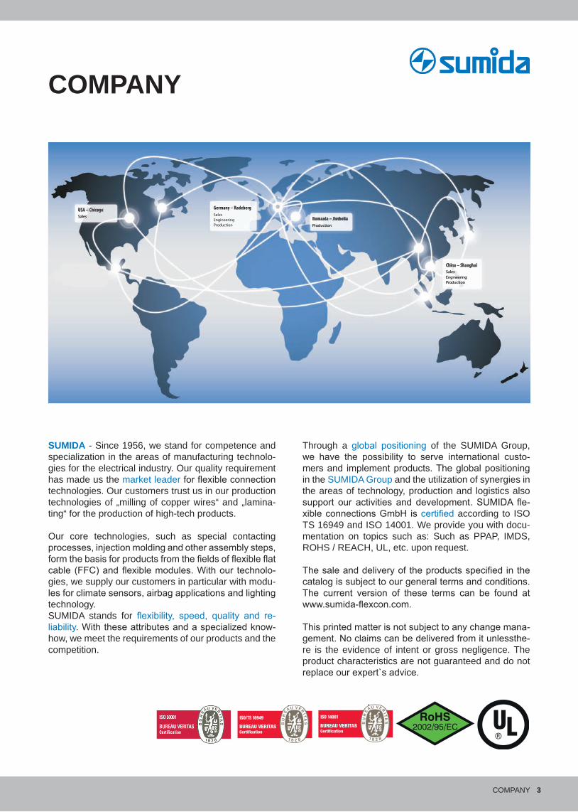
USA – ChicagoSales
Germany – RadebergSalesEngineering Production
Romania – JimboliaProduction
China – ShanghaiSalesEngineeringProduction
COMPANY
COMPANY
SUMIDA - Since 1956, we stand for competence and specialization in the areas of manufacturing technolo-gies for the electrical industry. Our quality requirement has made us the market leader for fl exible connection technologies. Our customers trust us in our production technologies of „milling of copper wires“ and „lamina-ting“ for the production of high-tech products.
Our core technologies, such as special contacting processes, injection molding and other assembly steps, form the basis for products from the fi elds of fl exible fl at cable (FFC) and fl exible modules. With our technolo-gies, we supply our customers in particular with modu-les for climate sensors, airbag applications and lighting technology.SUMIDA stands for fl exibility, speed, quality and re-liability. With these attributes and a specialized know-how, we meet the requirements of our products and the competition.
Through a global positioning of the SUMIDA Group, we have the possibility to serve international custo-mers and implement products. The global positioning in the SUMIDA Group and the utilization of synergies in the areas of technology, production and logistics also support our activities and development. SUMIDA fl e-xible connections GmbH is certifi ed according to ISO TS 16949 and ISO 14001. We provide you with docu-mentation on topics such as: Such as PPAP, IMDS, ROHS / REACH, UL, etc. upon request.
The sale and delivery of the products specifi ed in the catalog is subject to our general terms and conditions. The current version of these terms can be found at www.sumida-fl excon.com.
This printed matter is not subject to any change mana-gement. No claims can be delivered from it unlessthe-re is the evidence of intent or gross negligence. The product characteristics are not guaranteed and do not replace our expertˋs advice.

5
FLEXIBLE BOARD CONNECTIONS (FBC)
6
PANTA® FIX JUMPER
PANTA® FIX JUMPER
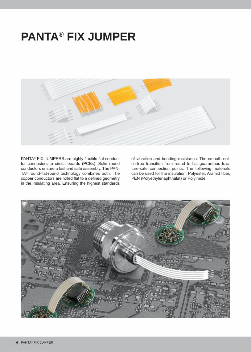
PANTA® FIX JUMPERS are highly fl exible fl at conduc-tor connectors to circuit boards (PCBs). Solid round conductors ensure a fast and safe assembly. The PAN-TA® round-fl at-round technology combines both. The copper conductors are rolled fl at to a defi ned geometry in the insulating area. Ensuring the highest standards
of vibration and bending resistance. The smooth not-ch-free transition from round to fl at guarantees frac-ture-safe connection points. The following materials can be used for the insulation: Polyester, Aramid fi ber, PEN (Polyethylenaphthalat) or Polyimide.
7PANTA® FIX JUMPER
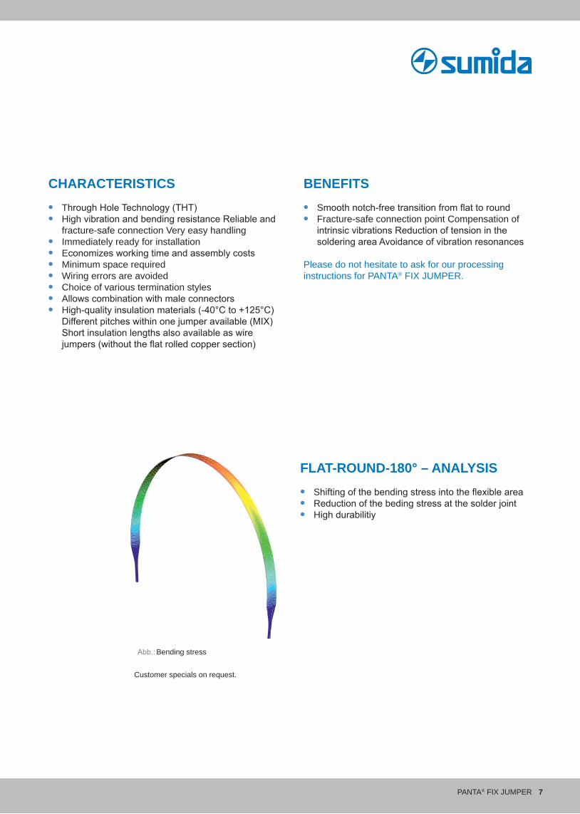
CHARACTERISTICS
• Through Hole Technology (THT)• High vibration and bending resistance Reliable and
fracture-safe connection Very easy handling• Immediately ready for installation• Economizes working time and assembly costs• Minimum space required• Wiring errors are avoided• Choice of various termination styles• Allows combination with male connectors• High-quality insulation materials (-40°C to +125°C)
Different pitches within one jumper available (MIX) Short insulation lengths also available as wire jumpers (without the fl at rolled copper section)
BENEFITS
• Smooth notch-free transition from fl at to round• Fracture-safe connection point Compensation of
intrinsic vibrations Reduction of tension in the soldering area Avoidance of vibration resonances
Please do not hesitate to ask for our processing instructions for PANTA® FIX JUMPER.
Abb.: Bending stress
Customer specials on request.
FLAT-ROUND-180° – ANALYSIS
• Shifting of the bending stress into the fl exible area • Reduction of the beding stress at the solder joint • High durabilitiy
8
B
G
GD
C
A
B
PANTA® FIX JUMPER
PANTA® FIX JUMPER
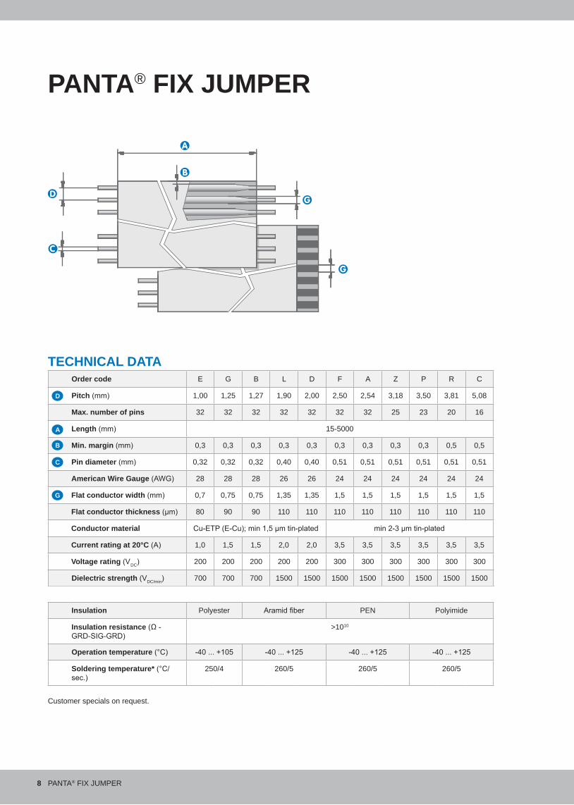
TECHNICAL DATAOrder code E G B L D F A Z P R C
Pitch (mm) 1,00 1,25 1,27 1,90 2,00 2,50 2,54 3,18 3,50 3,81 5,08
Max. number of pins 32 32 32 32 32 32 32 25 23 20 16
Length (mm) 15-5000
Min. margin (mm) 0,3 0,3 0,3 0,3 0,3 0,3 0,3 0,3 0,3 0,5 0,5
Pin diameter (mm) 0,32 0,32 0,32 0,40 0,40 0,51 0,51 0,51 0,51 0,51 0,51
American Wire Gauge (AWG) 28 28 28 26 26 24 24 24 24 24 24
Flat conductor width (mm) 0,7 0,75 0,75 1,35 1,35 1,5 1,5 1,5 1,5 1,5 1,5
Flat conductor thickness (µm) 80 90 90 110 110 110 110 110 110 110 110
Conductor material Cu-ETP (E-Cu); min 1,5 µm tin-plated min 2-3 µm tin-plated
Current rating at 20°C (A) 1,0 1,5 1,5 2,0 2,0 3,5 3,5 3,5 3,5 3,5 3,5
Voltage rating (VDC) 200 200 200 200 200 300 300 300 300 300 300
Dielectric strength (VDC/min) 700 700 700 1500 1500 1500 1500 1500 1500 1500 1500
Insulation Polyester Aramid fiber PEN Polyimide
Insulation resistance (Ω - GRD-SIG-GRD)
>1010
Operation temperature (°C) -40 ... +105 -40 ... +125 -40 ... +125 -40 ... +125
Soldering temperature* (°C/sec.)
250/4 260/5 260/5 260/5
Customer specials on request.
D
A
B
C
G
9
A
PIN 1
B
PIN 1
C
PIN 1
Z
PIN 1
G
PIN 1
F
PIN 1
E
PIN 1
D
PIN 1
H
PIN 1
J
PIN 1
K
PIN 1
L
PIN 1 A
N
PIN 1
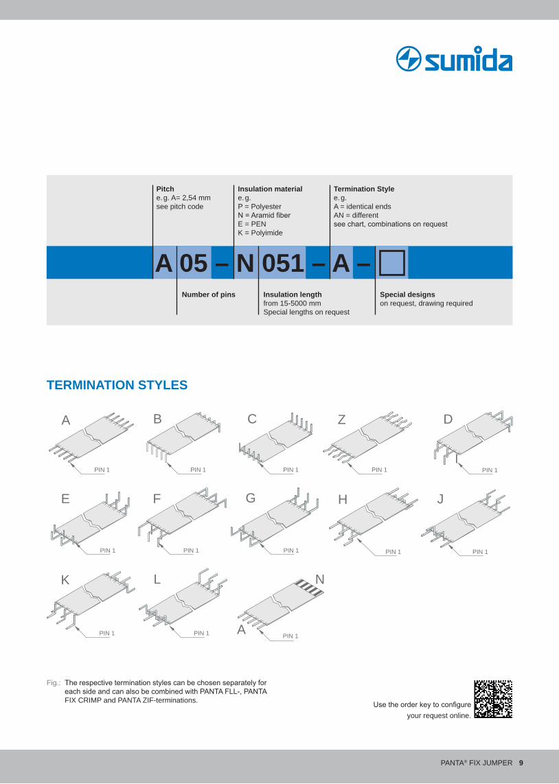
A 05 – N 051 – A –
PANTA® FIX JUMPER
TERMINATION STYLES
Pitche. g. A= 2,54 mm see pitch code
Number of pins
Insulation materiale. g. P = PolyesterN = Aramid fi berE = PENK = Polyimide
Insulation lengthfrom 15-5000 mmSpecial lengths on request
Special designson request, drawing required
Termination Stylee. g. A = identical endsAN = differentsee chart, combinations on request
Fig.: The respective termination styles can be chosen separately for each side and can also be combined with PANTA FLL-, PANTA FIX CRIMP and PANTA ZIF-terminations. Use the order key to confi gure
your request online.
10
PANTA® HT JUMPER
PANTA® HT JUMPER
BENEFITS
• Smooth notch-free transition from fl at to round• Fracture-safe connection point Compensation of
intrinsic vibrations Reduction of tension in the sol-dering area Avoidance of vibration resonances
Please do not hesitate to ask for our processing instructions for PANTA® HT Jumper.
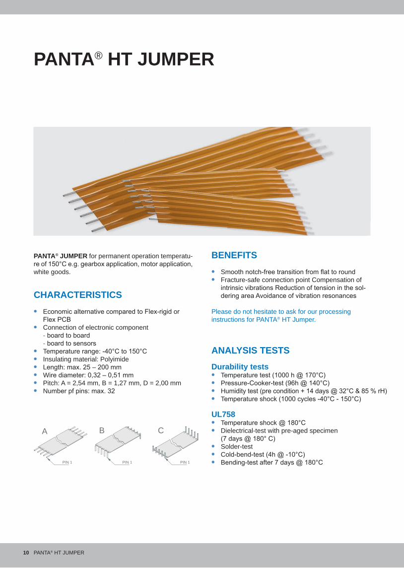
PANTA® JUMPER for permanent operation temperatu-re of 150°C e.g. gearbox application, motor application, white goods.
CHARACTERISTICS
• Economic alternative compared to Flex-rigid or Flex PCB
• Connection of electronic component- board to board- board to sensors
• Temperature range: -40°C to 150°C • Insulating material: Polyimide• Length: max. 25 – 200 mm• Wire diameter: 0,32 – 0,51 mm• Pitch: A = 2,54 mm, B = 1,27 mm, D = 2,00 mm• Number pf pins: max. 32
ANALYSIS TESTSDurability tests• Temperature test (1000 h @ 170°C)• Pressure-Cooker-test (96h @ 140°C)• Humidity test (pre condition + 14 days @ 32°C & 85 % rH)• Temperature shock (1000 cycles -40°C - 150°C)
UL758• Temperature shock @ 180°C• Dielectrical-test with pre-aged specimen
(7 days @ 180° C)• Solder-test• Cold-bend-test (4h @ -10°C)• Bending-test after 7 days @ 180°C
A
PIN 1
B
PIN 1
C
PIN 1
11PANTA® HT JUMPER
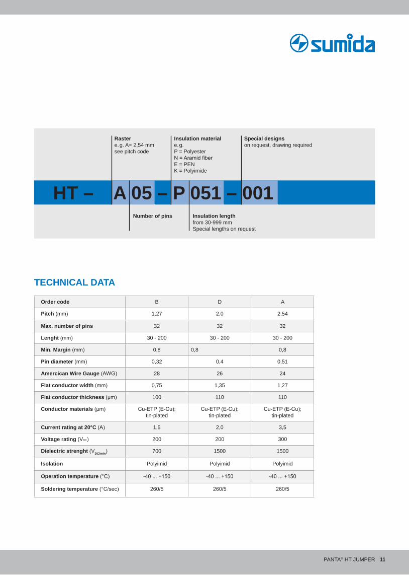
TECHNICAL DATA
Order code B D A
Pitch (mm) 1,27 2,0 2,54
Max. number of pins 32 32 32
Lenght (mm) 30 - 200 30 - 200 30 - 200
Min. Margin (mm) 0,8 0,8 0,8
Pin diameter (mm) 0,32 0,4 0,51
Amercican Wire Gauge (AWG) 28 26 24
Flat conductor width (mm) 0,75 1,35 1,27
Flat conductor thickness (µm) 100 110 110
Conductor materials (µm) Cu-ETP (E-Cu);tin-plated
Cu-ETP (E-Cu);tin-plated
Cu-ETP (E-Cu);tin-plated
Current rating at 20°C (A) 1,5 2,0 3,5
Voltage rating (VDC) 200 200 300
Dielectric strenght (VDC/min) 700 1500 1500
Isolation Polyimid Polyimid Polyimid
Operation temperature (°C) -40 ... +150 -40 ... +150 -40 ... +150
Soldering temperature (°C/sec) 260/5 260/5 260/5
A 05 – P 051 – 001 HT –
Rastere. g. A= 2,54 mm see pitch code
Number of pins
Insulation materiale. g. P = PolyesterN = Aramid fi berE = PENK = Polyimide
Insulation lengthfrom 30-999 mmSpecial lengths on request
Special designson request, drawing required
12
PANTA® SMD 0,93 mm pitch
PANTA® SMD 0,93 PITCH
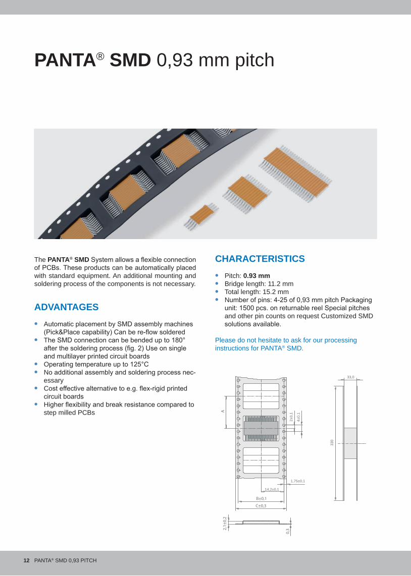
The PANTA® SMD System allows a fl exible connection of PCBs. These products can be automatically placed with standard equipment. An additional mounting and soldering process of the components is not necessary.
ADVANTAGES
• Automatic placement by SMD assembly machines (Pick&Place capability) Can be re-fl ow soldered
• The SMD connection can be bended up to 180° after the soldering process (fi g. 2) Use on single and multilayer printed circuit boards
• Operating temperature up to 125°C• No additional assembly and soldering process nec-
essary• Cost effective alternative to e.g. fl ex-rigid printed
circuit boards• Higher fl exibility and break resistance compared to
step milled PCBs
CHARACTERISTICS
• Pitch: 0.93 mm• Bridge length: 11.2 mm• Total length: 15.2 mm• Number of pins: 4-25 of 0,93 mm pitch Packaging
unit: 1500 pcs. on returnable reel Special pitches and other pin counts on request Customized SMD solutions available.
Please do not hesitate to ask for our processing instructions for PANTA® SMD.
33,0
330
2±0,
1
4±0,
1
1,75±0,1
14,2±0,1
B±0,1
C±0,3
0,32,
1±0,
2A
Feeding direction
(13,0 dia)
33,0
330
2±0,
1
4±0,
1
1,75±0,1
14,2±0,1
B±0,1
C±0,3
0,32,
1±0,
2A
Feeding direction
(13,0 dia)
13 PANTA® SMD
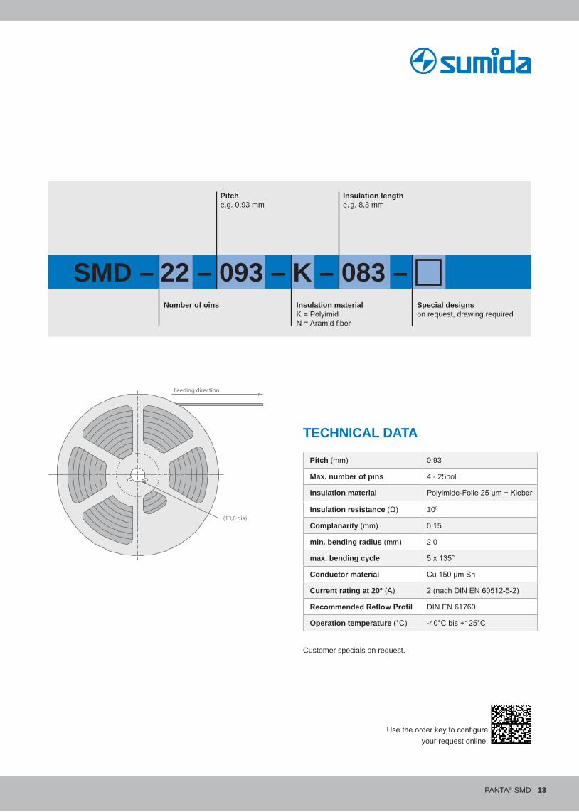
22 – 093 – K – 083 – SMD –
Pitche.g. 0,93 mm
Number of oins
Insulation lengthe. g. 8,3 mm
Insulation materialK = PolyimidN = Aramid fi ber
Special designson request, drawing required
TECHNICAL DATA
Pitch (mm) 0,93
Max. number of pins 4 - 25pol
Insulation material Polyimide-Folie 25 µm + Kleber
Insulation resistance (Ω) 108
Complanarity (mm) 0,15
min. bending radius (mm) 2,0
max. bending cycle 5 x 135°
Conductor material Cu 150 µm Sn
Current rating at 20° (A) 2 (nach DIN EN 60512-5-2)
Recommended Refl ow Profi l DIN EN 61760
Operation temperature (°C) -40°C bis +125°C
Customer specials on request.
Use the order key to confi gure your request online.
33,0
330
2±0,
1
4±0,
1
1,75±0,1
14,2±0,1
B±0,1
C±0,3
0,32,
1±0,
2A
Feeding direction
(13,0 dia)
14
PANTA® SMD 0,50 mm pitch
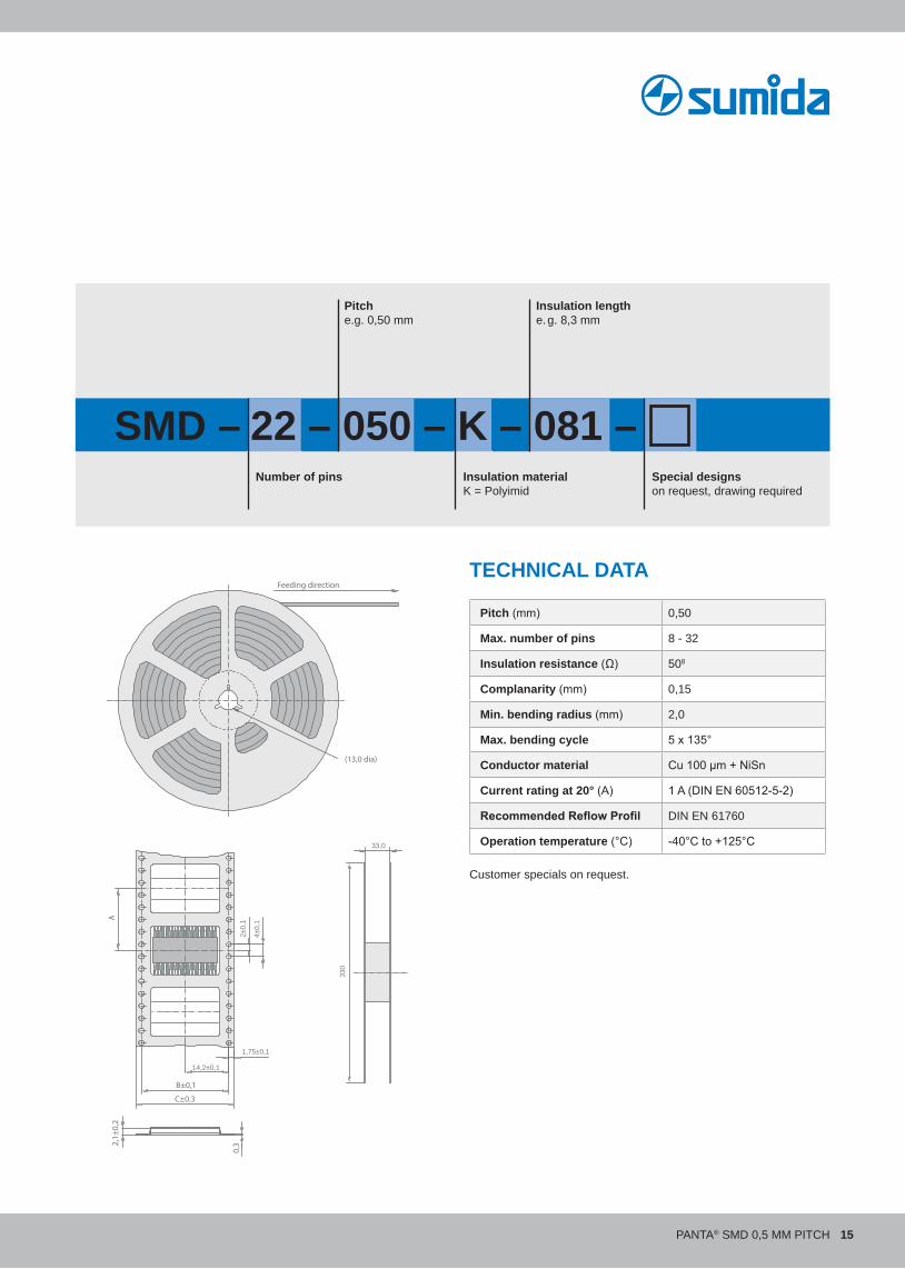
PANTA® SMD 0,5 MM PITCH
NEW
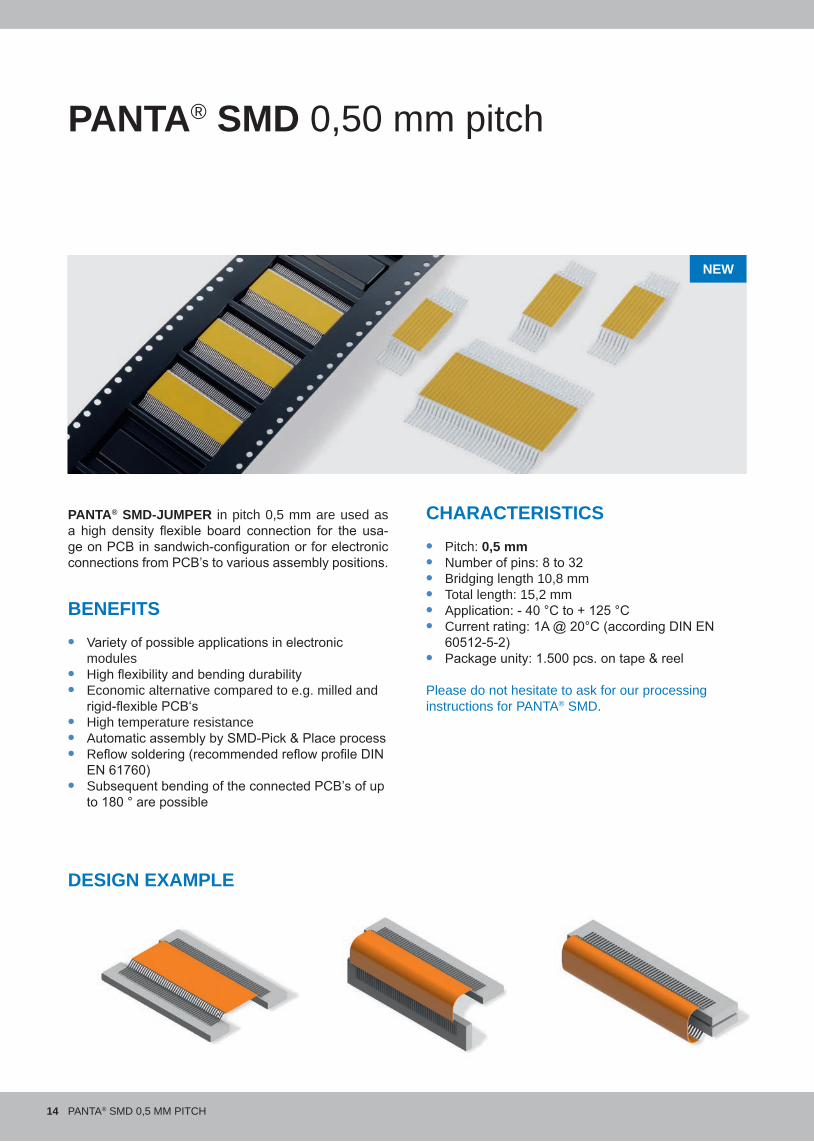
PANTA® SMD-JUMPER in pitch 0,5 mm are used as a high density fl exible board connection for the usa-ge on PCB in sandwich-confi guration or for electronic connections from PCB’s to various assembly positions.
BENEFITS
• Variety of possible applications in electronic modules
• High fl exibility and bending durability• Economic alternative compared to e.g. milled and
rigid-fl exible PCB‘s• High temperature resistance• Automatic assembly by SMD-Pick & Place process• Refl ow soldering (recommended refl ow profi le DIN
EN 61760)• Subsequent bending of the connected PCB’s of up
to 180 ° are possible
CHARACTERISTICS
• Pitch: 0,5 mm• Number of pins: 8 to 32• Bridging length 10,8 mm• Total length: 15,2 mm• Application: - 40 °C to + 125 °C• Current rating: 1A @ 20°C (according DIN EN
60512-5-2)• Package unity: 1.500 pcs. on tape & reel
Please do not hesitate to ask for our processing instructions for PANTA® SMD.
DESIGN EXAMPLE
15PANTA® SMD 0,5 MM PITCH
22 – 050 – K – 081 – SMD –
Pitche.g. 0,50 mm
Number of pins
Insulation lengthe. g. 8,3 mm
Insulation materialK = Polyimid
Special designson request, drawing required
TECHNICAL DATA
Pitch (mm) 0,50
Max. number of pins 8 - 32
Insulation resistance (Ω) 508
Complanarity (mm) 0,15
Min. bending radius (mm) 2,0
Max. bending cycle 5 x 135°
Conductor material Cu 100 µm + NiSn
Current rating at 20° (A) 1 A (DIN EN 60512-5-2)
Recommended Refl ow Profi l DIN EN 61760
Operation temperature (°C) -40°C to +125°C
Customer specials on request.
33,0
330
2±0,
1
4±0,
1
1,75±0,1
14,2±0,1
B±0,1
C±0,3
0,32,
1±0,
2A
Feeding direction
(13,0 dia)
33,0
330
2±0,
1
4±0,
1
1,75±0,1
14,2±0,1
B±0,1
C±0,3
0,32,
1±0,
2A
Feeding direction
(13,0 dia)
33,0
330
2±0,
1
4±0,
1
1,75±0,1
14,2±0,1
B±0,1
C±0,3
0,32,
1±0,
2A
Feeding direction
(13,0 dia)
16
PANTA® FLL
PANTA® FLL
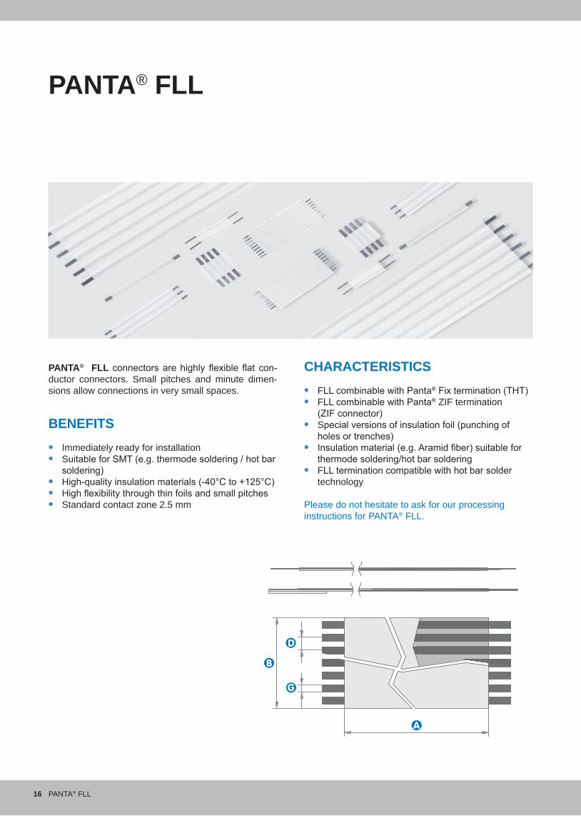
PANTA® FLL connectors are highly fl exible fl at con-ductor connectors. Small pitches and minute dimen-sions allow connections in very small spaces.
BENEFITS
• Immediately ready for installation• Suitable for SMT (e.g. thermode soldering / hot bar
soldering) • High-quality insulation materials (-40°C to +125°C)• High fl exibility through thin foils and small pitches• Standard contact zone 2.5 mm
CHARACTERISTICS
• FLL combinable with Panta® Fix termination (THT)• FLL combinable with Panta® ZIF termination
(ZIF connector)• Special versions of insulation foil (punching of
holes or trenches)• Insulation material (e.g. Aramid fi ber) suitable for
thermode soldering/hot bar soldering• FLL termination compatible with hot bar solder
technology
Please do not hesitate to ask for our processing instructions for PANTA® FLL.
A
B
D
G
17
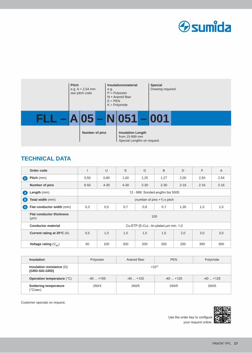
A 05 – N 051 – 001 FLL –
PANTA® FFL
Pitche.g. A = 2,54 mm see pitch code
Number of pins
Insulationsmateriale.g. P = PolyesterN = Aramid fi berE = PENK = Polyimide
Insulation Lengthfrom 15-999 mmSpecial Lengthn on request
SpecialDrawing required
TECHNICAL DATA
Order code I U E G B D F A
Pitch (mm) 0,50 0,80 1,00 1,25 1,27 2,00 2,50 2,54
Number of pins 6-50 4-30 4-30 2-30 2-30 2-16 2-16 2-16
Length (mm) 12 - 999; SonderLengthn bis 5000
Total width (mm) (number of pins +1) x pitch
Flat conductor width (mm) 0,3 0,5 0,7 0,8 0,7 1,35 1,5 1,5
Flat conductor thickness (µm) 100
Conductor material Cu-ETP (E-Cu) ; tin-plated µm min. 1,0
Current rating at 20°C (A) 0,5 1,0 1,0 1,5 1,5 2,0 3,0 3,0
Voltage rating (VDC) 60 100 200 200 200 200 300 300
Insulation Polyester Aramid fi ber PEN Polyimide
Insulation resistance (Ω)(GRD-SIG-GRD)
>1010
Operation temperature (°C) -40 ... +105 -40 ... +125 -40 ... +125 -40 ... +125
Soldering temperature (°C/sec)
250/4 260/5 260/5 260/5
Customer specials on request.
Use the order key to confi gure your request online.
D
A
B
G

18
PANTA® ZIF JUMPER
PANTA® ZIF JUMPER
PANTA® ZIF JUMPERS (FFC-Cable) are used for con-necting printed circuit boards (PCBs). Compatible with ZIF-connectors (Zero Insertion Force) or LIF-connec-tors (Low Insertion Force). The cable can be delivered with a gold plated surface to prevent whisker-growths.
BENEFITS
• Defi ned stripping of insulation and application of stiffener in the contact area provides secure con-nection to all conventional connection systems (e.g. Iriso, FCI, Molex, Tyco, JST etc.)
• small dimensions due to thin foils and small pitches possible
• Fast assembly by simple insertion• High fl exibility and bending resistance• Special versions available, e.g. LIF/ZIF • pins can be combined with round solder pins• (Panta® FIX) or SMD solderable fl at conductors
(Panta® FLL)• Optional custom design of jumper mating area al-
lows the use of specifi c connectors with additional features. Specifi c punch at jumper ends provides a strain relief functionality and connector position assurance (e.g. Iriso I-Lock or similar)
CHARACTERISTICS
• Available pitches 0,5; 1,0; 1,25 and 2,54 mm• Temperature range -40°C … 105°C• Copper wire can be bladed with tin or gold• Customer specifi c design for contact area and rein-
forcements
BENEFITS OF THE GOLD PLATING
• Low contact resistance• Increased number of mating cycles• Low current voltages• Prevention of whisker effect for small centerlines• Connection with NiAu-plated connectors
Please do not hesitate to ask for our processing instructions for PANTA® ZIF Jumper.
A
B
D
G
H H
K K
E
E
W
NN
19
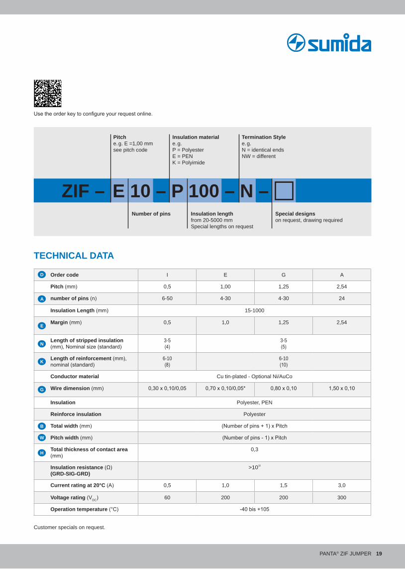
E 10 – P 100 – N – ZIF –
PANTA® ZIF JUMPER
Pitche. g. E =1,00 mm see pitch code
Number of pins
Insulation materiale. g. P = PolyesterE = PENK = Polyimide
Insulation lengthfrom 20-5000 mmSpecial lengths on request
Special designson request, drawing required
Termination Stylee. g. N = identical endsNW = different
TECHNICAL DATA
Order code I E G A
Pitch (mm) 0,5 1,00 1,25 2,54
number of pins (n) 6-50 4-30 4-30 24
Insulation Length (mm) 15-1000
Margin (mm) 0,5 1,0 1,25 2,54
Length of stripped insulation (mm), Nominal size (standard)
3-5 (4)
3-5 (5)
Length of reinforcement (mm), nominal (standard)
6-10 (8)
6-10 (10)
Conductor material Cu tin-plated - Optional Ni/AuCo
Wire dimension (mm) 0,30 x 0,10/0,05 0,70 x 0,10/0,05* 0,80 x 0,10 1,50 x 0,10
Insulation Polyester, PEN
Reinforce insulation Polyester
Total width (mm) (Number of pins + 1) x Pitch
Pitch width (mm) (Number of pins - 1) x Pitch
Total thickness of contact area (mm)
0,3
Insulation resistance (Ω)(GRD-SIG-GRD)
>1010
Current rating at 20°C (A) 0,5 1,0 1,5 3,0
Voltage rating (VDC) 60 200 200 300
Operation temperature (°C) -40 bis +105
Customer specials on request.
Use the order key to confi gure your request online.
D
A
E
N
K
G
B
W
H
20
PANTA® FIX CRIMP
PANTA® FIX CRIMP
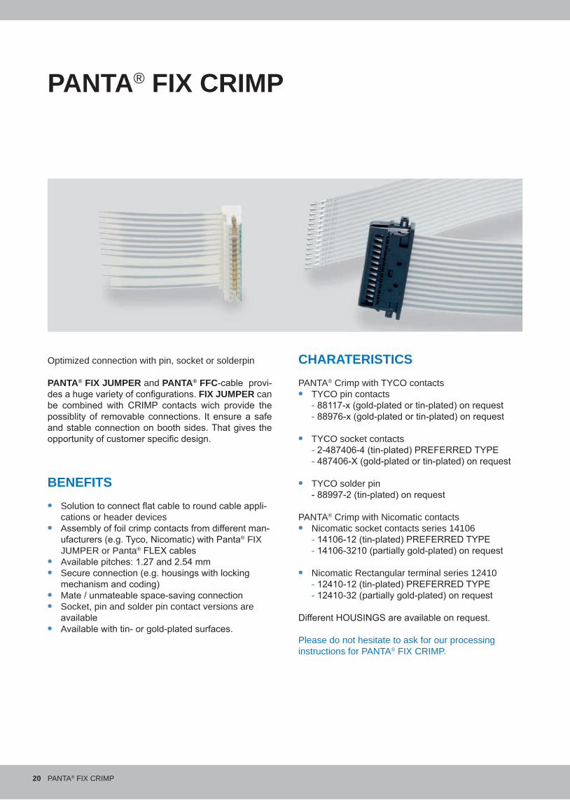
Optimized connection with pin, socket or solderpin
PANTA® FIX JUMPER and PANTA® FFC-cable provi-des a huge variety of confi gurations. FIX JUMPER can be combined with CRIMP contacts wich provide the possiblity of removable connections. It ensure a safe and stable connection on booth sides. That gives the opportunity of customer specifi c design.
BENEFITS
• Solution to connect fl at cable to round cable appli-cations or header devices
• Assembly of foil crimp contacts from different man-ufacturers (e.g. Tyco, Nicomatic) with Panta® FIX JUMPER or Panta® FLEX cables
• Available pitches: 1.27 and 2.54 mm• Secure connection (e.g. housings with locking
mechanism and coding) • Mate / unmateable space-saving connection• Socket, pin and solder pin contact versions are
available• Available with tin- or gold-plated surfaces.
CHARATERISTICSPANTA® Crimp with TYCO contacts• TYCO pin contacts
- 88117-x (gold-plated or tin-plated) on request- 88976-x (gold-plated or tin-plated) on request
• TYCO socket contacts- 2-487406-4 (tin-plated) PREFERRED TYPE- 487406-X (gold-plated or tin-plated) on request
• TYCO solder pin- 88997-2 (tin-plated) on request
PANTA® Crimp with Nicomatic contacts• Nicomatic socket contacts series 14106
- 14106-12 (tin-plated) PREFERRED TYPE- 14106-3210 (partially gold-plated) on request
• Nicomatic Rectangular terminal series 12410- 12410-12 (tin-plated) PREFERRED TYPE- 12410-32 (partially gold-plated) on request
Different HOUSINGS are available on request.
Please do not hesitate to ask for our processing instructions for PANTA® FIX CRIMP.
21
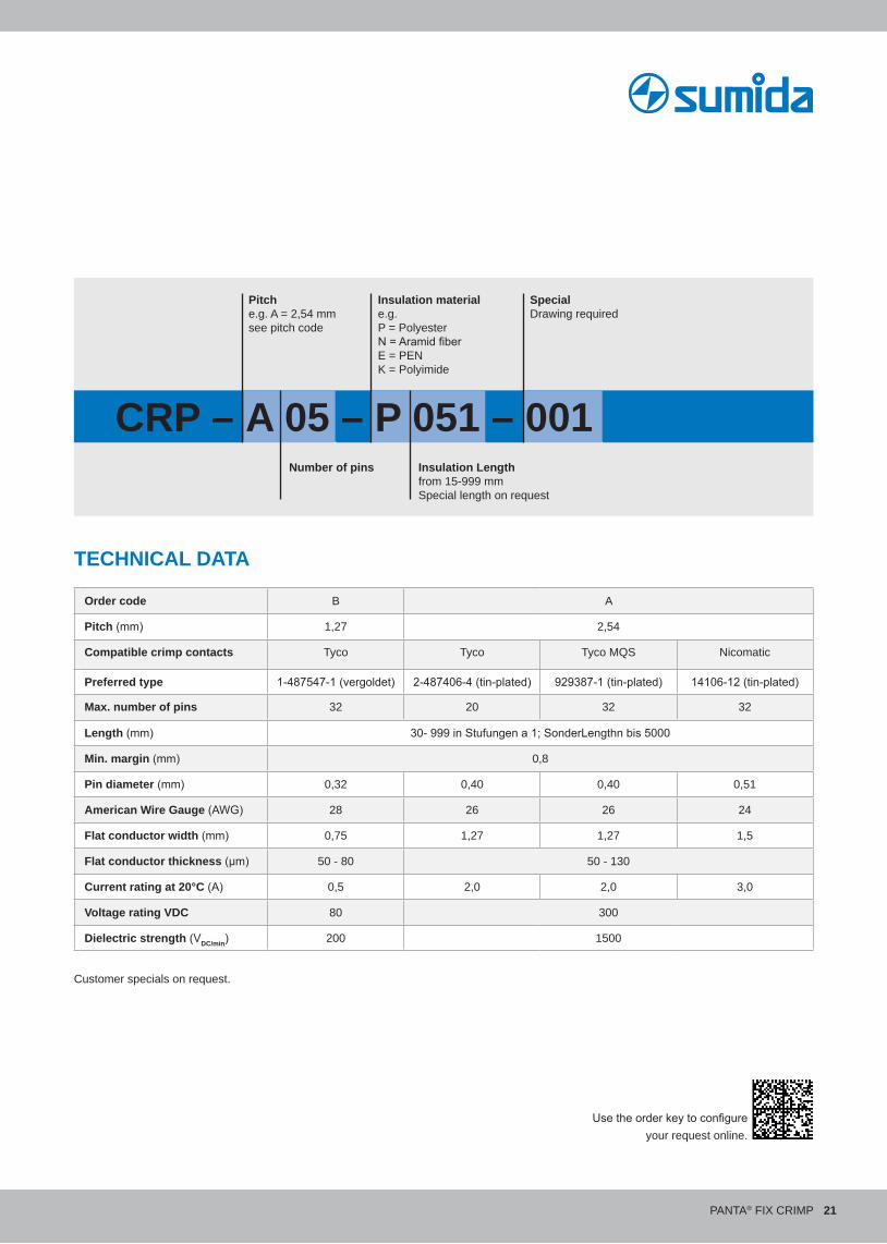
A 05 – P 051 – 001 CRP –
PANTA® FIX CRIMP
Pitche.g. A = 2,54 mm see pitch code
Number of pins
Insulation materiale.g. P = PolyesterN = Aramid fi berE = PENK = Polyimide
Insulation Lengthfrom 15-999 mmSpecial length on request
SpecialDrawing required
TECHNICAL DATA
Order code B A
Pitch (mm) 1,27 2,54
Compatible crimp contacts Tyco Tyco Tyco MQS Nicomatic
Preferred type 1-487547-1 (vergoldet) 2-487406-4 (tin-plated) 929387-1 (tin-plated) 14106-12 (tin-plated)
Max. number of pins 32 20 32 32
Length (mm) 30- 999 in Stufungen a 1; SonderLengthn bis 5000
Min. margin (mm) 0,8
Pin diameter (mm) 0,32 0,40 0,40 0,51
American Wire Gauge (AWG) 28 26 26 24
Flat conductor width (mm) 0,75 1,27 1,27 1,5
Flat conductor thickness (µm) 50 - 80 50 - 130
Current rating at 20°C (A) 0,5 2,0 2,0 3,0
Voltage rating VDC 80 300
Dielectric strength (VDC/min) 200 1500
Customer specials on request.
Use the order key to confi gure your request online.
22
PANTA® FIX POWER
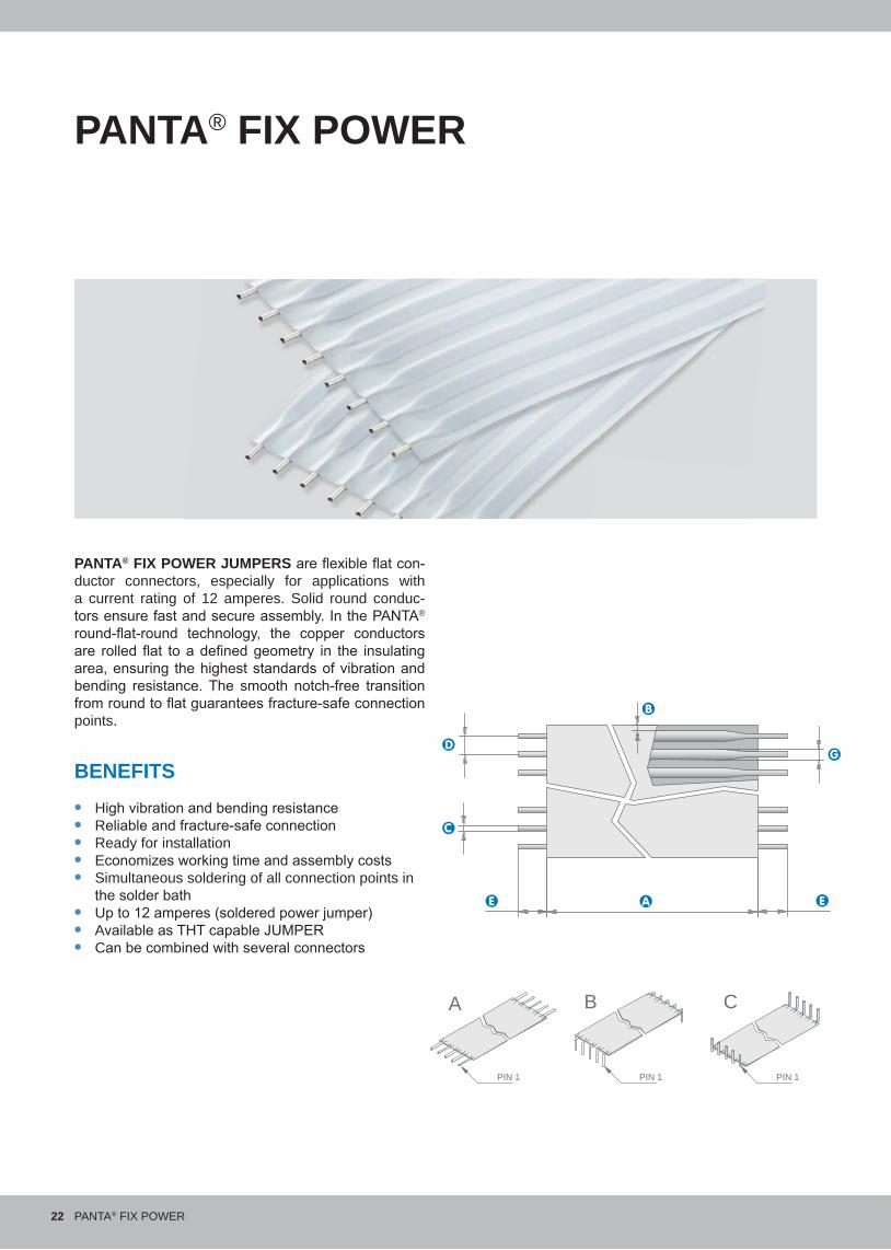
PANTA® FIX POWER
PANTA® FIX POWER JUMPERS are fl exible fl at con-ductor connectors, especially for applications with a current rating of 12 amperes. Solid round conduc-tors ensure fast and secure assembly. In the PANTA® round-fl at-round technology, the copper conductors are rolled fl at to a defi ned geometry in the insulating area, ensuring the highest standards of vibration and bending resistance. The smooth notch-free transition from round to fl at guarantees fracture-safe connection points.
BENEFITS
• High vibration and bending resistance • Reliable and fracture-safe connection • Ready for installation• Economizes working time and assembly costs• Simultaneous soldering of all connection points in
the solder bath• Up to 12 amperes (soldered power jumper)• Available as THT capable JUMPER• Can be combined with several connectors
B
C
D
A
G
EE
A
PIN 1
B
PIN 1
C
PIN 1
23
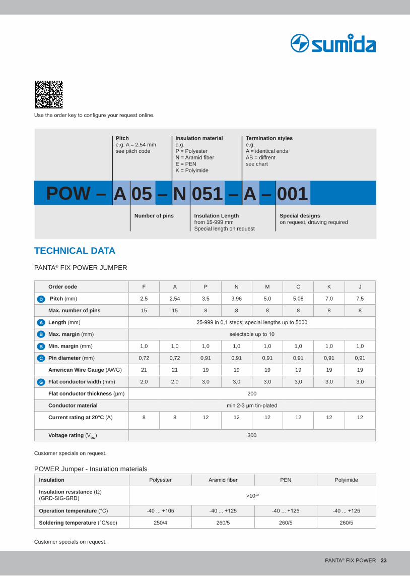
A 05 – N 051 – A – 001 POW –
PANTA® FIX POWER
Pitche.g. A = 2,54 mm see pitch code
Number of pins
Insulation materiale.g. P = PolyesterN = Aramid fi berE = PENK = Polyimide
Insulation Lengthfrom 15-999 mmSpecial length on request
Special designson request, drawing required
Termination stylese.g. A = identical endsAB = diffrentsee chart
TECHNICAL DATAPANTA® FIX POWER JUMPER
Order code F A P N M C K J
Pitch (mm) 2,5 2,54 3,5 3,96 5,0 5,08 7,0 7,5
Max. number of pins 15 15 8 8 8 8 8 8
Length (mm) 25-999 in 0,1 steps; special lengths up to 5000
Max. margin (mm) selectable up to 10
Min. margin (mm) 1,0 1,0 1,0 1,0 1,0 1,0 1,0 1,0
Pin diameter (mm) 0,72 0,72 0,91 0,91 0,91 0,91 0,91 0,91
American Wire Gauge (AWG) 21 21 19 19 19 19 19 19
Flat conductor width (mm) 2,0 2,0 3,0 3,0 3,0 3,0 3,0 3,0
Flat conductor thickness (µm) 200
Conductor material min 2-3 µm tin-plated
Current rating at 20°C (A) 8 8 12 12 12 12 12 12
Voltage rating (VDC) 300
Customer specials on request.
POWER Jumper - Insulation materialsInsulation Polyester Aramid fi ber PEN Polyimide
Insulation resistance (Ω)(GRD-SIG-GRD) >1010
Operation temperature (°C) -40 ... +105 -40 ... +125 -40 ... +125 -40 ... +125
Soldering temperature (°C/sec) 250/4 260/5 260/5 260/5
Customer specials on request.
D
A
B
B
C
G
Use the order key to confi gure your request online.
24
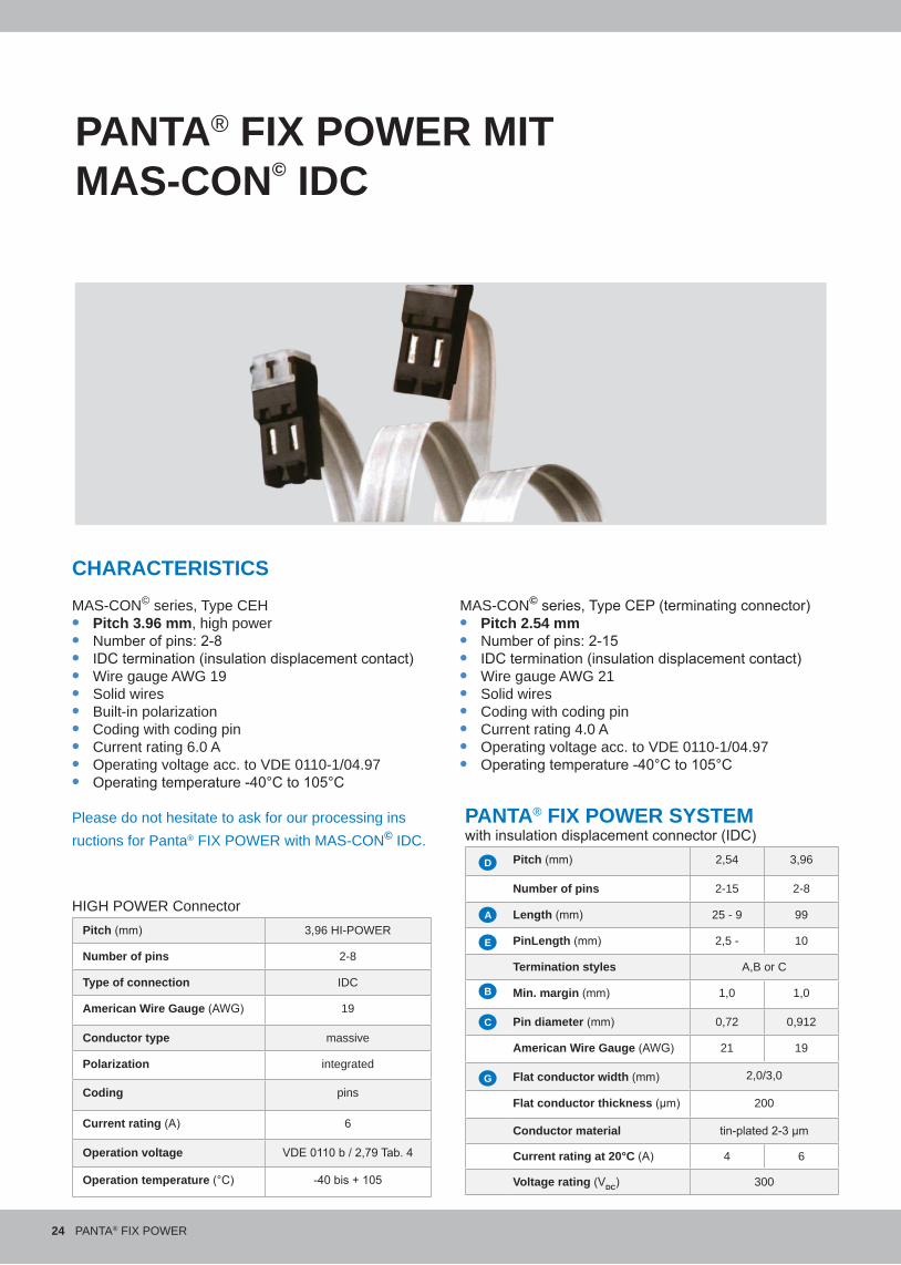
PANTA® FIX POWER MITMAS-CON© IDC
PANTA® FIX POWER SYSTEMwith insulation displacement connector (IDC)
Pitch (mm) 2,54 3,96
Number of pins 2-15 2-8
Length (mm) 25 - 9 99
PinLength (mm) 2,5 - 10
Termination styles A,B or C
Min. margin (mm) 1,0 1,0
Pin diameter (mm) 0,72 0,912
American Wire Gauge (AWG) 21 19
Flat conductor width (mm) 2,0/3,0
Flat conductor thickness (µm) 200
Conductor material tin-plated 2-3 µm
Current rating at 20°C (A) 4 6
Voltage rating (VDC) 300
HIGH POWER ConnectorPitch (mm) 3,96 HI-POWER
Number of pins 2-8
Type of connection IDC
American Wire Gauge (AWG) 19
Conductor type massive
Polarization integrated
Coding pins
Current rating (A) 6
Operation voltage VDE 0110 b / 2,79 Tab. 4
Operation temperature (°C) -40 bis + 105
CHARACTERISTICSMAS-CON© series, Type CEH• Pitch 3.96 mm, high power• Number of pins: 2-8• IDC termination (insulation displacement contact)• Wire gauge AWG 19• Solid wires• Built-in polarization• Coding with coding pin• Current rating 6.0 A• Operating voltage acc. to VDE 0110-1/04.97• Operating temperature -40°C to 105°C
Please do not hesitate to ask for our processing insructions for Panta® FIX POWER with MAS-CON© IDC.
MAS-CON© series, Type CEP (terminating connector)• Pitch 2.54 mm• Number of pins: 2-15• IDC termination (insulation displacement contact)• Wire gauge AWG 21• Solid wires• Coding with coding pin• Current rating 4.0 A• Operating voltage acc. to VDE 0110-1/04.97• Operating temperature -40°C to 105°C
D
A
E
B
C
G
PANTA® FIX POWER
25
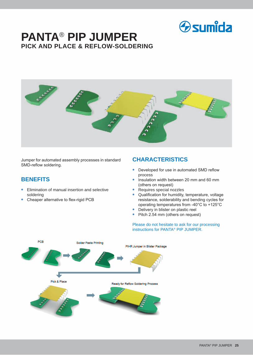
PANTA® PIP JUMPERPICK AND PLACE & REFLOW-SOLDERING
Jumper for automated assembly processes in standard SMD-refl ow soldering.
BENEFITS
• Elimination of manual insertion and selective soldering
• Cheaper alternative to fl ex-rigid PCB
CHARACTERISTICS
• Developed for use in automated SMD refl ow process
• Insulation width between 20 mm and 60 mm (others on request)
• Requires special nozzles • Qualifi cation for humidity, temperature, voltage
resistance, solderability and bending cycles for operating temperatures from -40°C to +125°C
• Delivery in blister on plastic reel• Pitch 2.54 mm (others on request)
Please do not hesitate to ask for our processing instructions for PANTA® PIP JUMPER.
PANTA® PIP JUMPER

27
FLEXIBLE FLAT CABLES (FFC)
28
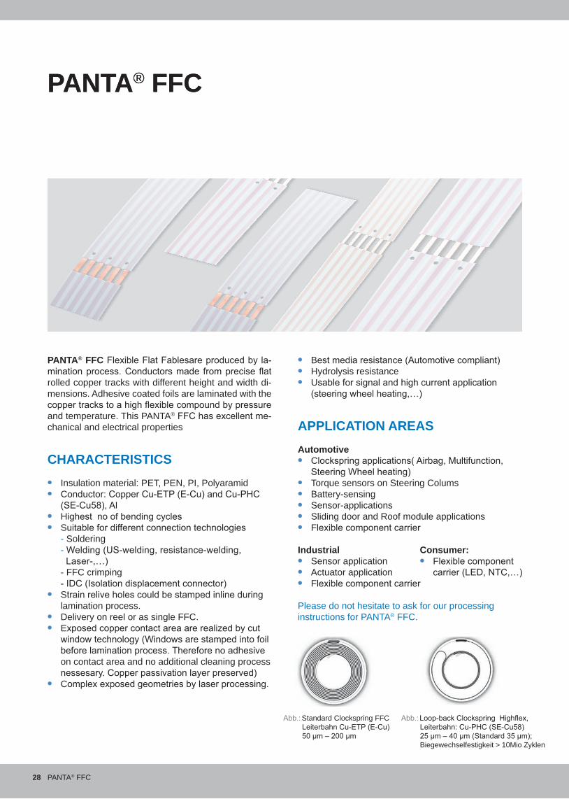
PANTA® FFCPANTA® FFC
Abb.: Standard Clockspring FFC Leiterbahn Cu-ETP (E-Cu) 50 µm – 200 µm
Abb.: Loop-back Clockspring Highfl ex, Leiterbahn: Cu-PHC (SE-Cu58) 25 µm – 40 µm (Standard 35 µm); Biegewechselfestigkeit > 10Mio Zyklen
PANTA® FFC Flexible Flat Fablesare produced by la-mination process. Conductors made from precise fl at rolled copper tracks with different height and width di-mensions. Adhesive coated foils are laminated with the copper tracks to a high fl exible compound by pressure and temperature. This PANTA® FFC has excellent me-chanical and electrical properties
CHARACTERISTICS
• Insulation material: PET, PEN, PI, Polyaramid• Conductor: Copper Cu-ETP (E-Cu) and Cu-PHC
(SE-Cu58), Al• Highest no of bending cycles • Suitable for different connection technologies
- Soldering- Welding (US-welding, resistance-welding, Laser-,…)- FFC crimping- IDC (Isolation displacement connector)
• Strain relive holes could be stamped inline during lamination process.
• Delivery on reel or as single FFC.• Exposed copper contact area are realized by cut
window technology (Windows are stamped into foil before lamination process. Therefore no adhesive on contact area and no additional cleaning process nessesary. Copper passivation layer preserved)
• Complex exposed geometries by laser processing.
• Best media resistance (Automotive compliant)• Hydrolysis resistance• Usable for signal and high current application
(steering wheel heating,…)
APPLICATION AREASAutomotive• Clockspring applications( Airbag, Multifunction,
Steering Wheel heating)• Torque sensors on Steering Colums • Battery-sensing• Sensor-applications• Sliding door and Roof module applications• Flexible component carrier
Industrial• Sensor application• Actuator application• Flexible component carrier
Please do not hesitate to ask for our processing instructions for PANTA® FFC.
Consumer:• Flexible component
carrier (LED, NTC,…)
PANTA® FFC
29
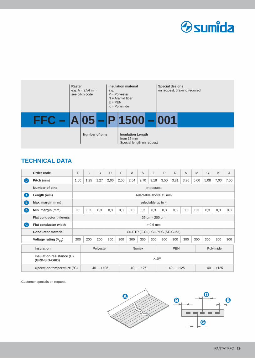
A 05 – P 1500 – 001 FFC –
Rastere.g. A = 2,54 mm see pitch code
Number of pins
Insulation materiale.g. P = PolyesterN = Aramid fi berE = PENK = Polyimide
Insulation Lengthfrom 15 mmSpecial length on request
Special designson request, drawing required
Consumer:• Flexible component
carrier (LED, NTC,…)
TECHNICAL DATA
Order code E G B D F A S Z P R N M C K J
Pitch (mm) 1,00 1,25 1,27 2,00 2,50 2,54 2,70 3,18 3,50 3,81 3,96 5,00 5,08 7,00 7,50
Number of pins on request
Length (mm) selectable above 15 mm
Max. margin (mm) selectable up to 4
Min. margin (mm) 0,3 0,3 0,3 0,3 0,3 0,3 0,3 0,3 0,3 0,3 0,3 0,3 0,3 0,3 0,3
Flat conductor thikness 35 µm - 200 µm
Flat conductor width > 0,6 mm
Conductor material Cu-ETP (E-Cu); Cu-PHC (SE-Cu58)
Voltage rating (VDC) 200 200 200 200 300 300 300 300 300 300 300 300 300 300 300
Insulation Polyester Nomex PEN Polyimide
Insulation resistance (Ω)(GRD-SIG-GRD) >1010
Operation temperature (°C) -40 ... +105 -40 ... +125 -40 ... +125 -40 ... +125
Customer specials on request.
D
A
B
B
G
AB B
D
G
PANTA® FFC

31
FLEXIBLE MODULES (FM)
32
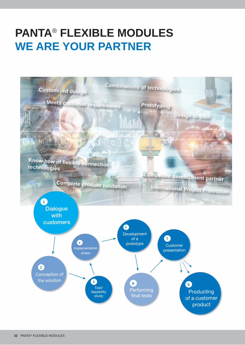
PANTA® FLEXIBLE MODULESWE ARE YOUR PARTNER
Producting of a customer
product
8
PANTA® FLEXIBLE MODULES
Dialoguewith
customers
1
Conception of the solution
2
Test/feasibility
study
3
Implementation
phase
4
Development of a
prototype
5
Customer presentation
7
Customized designCombinations of technologies
Meets customer requirements PrototypingDesign to cost
Know-how of fl exible connection technologiesCompetent development partnerComplete product validation International Project Protection
Copyright: Fotolia - sdecoret
Performingfi nal tests
6
33
PROCESS KNOWHOW
PROCESS KNOWHOW
LaminationLaminating is the process used to embed the copper conductor in insulating foil by using pressure and heat. The foils are coated with adhesive on one side. The copper conductors are parallel to each other. Different pitches can be combined.
CuttersThe laminated rolls are slit to the fi nal cable width. The lengths of the cables are produced by the cross cutting afterwards.
StrippingThe cable terminations are made in a stripping process. The insulation is stripped off the copper wires using a special cutter. The conductor ends can then be proces-sed further to the required termination style with speci-fi c bending tools.
Crimp-TechologyCrimp connections to fl at conductors of 1.27 mm and 2.54 mm pitch are possible with the crimping technolo-gy from Tyco and Nicomatic.
OvermoldingFully hydraulic injection molding machines can be used to overmold the cable ends of FFCs or to assemble FLEXIBLE MODULES. The maximum in- jection volu-me is 15 cm³ with a projected area of max. 75 cm².
Potting with Macromelt®
Macromelt® allows clean processability and does not contain any solvents or other harmful substances. Macromelt® is particularly suitable for applications that require good adhesion to conductor or housing materi-als at low processing pressure. Macromelt® is injected with low pressure into the cavities. It spreads gently around even the tiniest components, seals and protects the components.
StiffenersSpecial equipment places adhesive tapes and rein-forcements onto our FFCs and ZIF jumpers.
Laser ProcessingA highly precise, powerful 300 W CO² laser implements fast and very fl exible stripping modes.
SolderingSelective soldering systems ensure optimum solde-ring while minimizing the heat stress for components. A refl ow soldering system and placement systems are available for the assembly of SMD components.
Resistance WeldingThe contact between the components and PANTA® cables by means of resistance welding ensures a safe interface of very high quality. Welded fl exible modules are later potted or overmolded in order to secure the weld.
Assembly Lines• FAS - Flexible assembly systems ensure high qual-
ity modules even for lower volumes.• AAS - Automatic assembly systems produce high
volumes of customized modules in fully auto- matic operation.
The optimal assembly line is selected after a technical and qualitative assessment of the customiz
Design to cost
Competent development partnerInternational Project Protection
Copyright: Fotolia - sdecoret

34
MISSIONOur mission is to provide our customers with electronic solutions which enable them to develop products andtechnologies which improve our quality of life.
35
HIGH LEVEL PRODUCT DEVELOPMENT
FROM PROTOTYPETO SERIAL PRODUCTION
QUALITY AT A HIGH LEVEL
FLEXIBILITYRELIABILITY
DEVELOPMENT CUSTOMER SOLUTIONS

SUMIDA flexible connections GmbHAgathe-Zeis-Straße 501454 Radeberg
Tel.: +49 (0)3528 4040-30Fax: +49 (0)3528 4040-40E-Mail: [email protected]
Imprint: SUMIDA flexible connections GmbH, Agathe-Zeis-Straße 5, 01454 Radeberg All content, pictures (Cover: Fotolia - sdecoret) and illustrations, including those of the translation, are the property of SUMIDA flexible connections GmbH. Changes are possible any time (Information (month/year): 09/2017). This printed matter is not subject to any change management. No claims can be delivered from it unlessthere is the evidence of intent or gross negligence. The product characteristics are not guaranteed and do not replace our expertˋs advice.