Sugar Factory pH Control. - ISSCT Khainovsky... · · g on the ofcane a:.Carp yield multiplied by...
16
· g on the of cane a :.Carp yield multiplied by this d varies as low as .0.68 for othervarieties, factor is fixed for a actory by the Experiment Station, and is computed from the results of revious campaign. In the carbonatation factories, a greater elimination 'n-Sug ars occurs .. The actual yield can be 2-3 per cent. higher than the lated. For those with low extractions,high undetermined losses, &c., ecovery can be as much as 5 per cent. below the calculated. The Chairman asked Dr. Khainovsky to present his film dealing with development and operation of the electrical pH control equipment in n Sugar mills. Paper. Sugar Factory pH Control. * by V. KHAINOVSKY, tieo« Soleil, Monaco, l/mnce. Introduction. The colorimetric method of determining pH was introduced to the oJ avan ar factories in 1927. By 1928, 152 factories were employing this method 0 regulating the value of the clarified juice, and the Experiment Station epared, in 1930, a set of colour charts for use with nine separate indicators, 'apted for testing the full range of factory products. The general use of colorimetric method paved the way for the introduction of electrical pH termination; not only the European chemists, but also theJavanese operators ere acquainted with the general principles, and the successful adoption of 'ectrical pH control could be envisaged when the first experiments, were begun :1930. The electrometric method, by virtue of the complicated apparatus 'Valved, brought 0 with it many difficulties from which the colorimetric test as free. Several models were constructed; trie,d and abandoned, in the course' the experiments. :------ . , Fundamental Principles. Electrical pH control is based on the property of metallic electrodes mersed in a solution to change the electrical potential between the electrode , d the liquid proportional to the fluctuations in pfl : of the solution. If it ere possible to measure this potential, the change of pH would be available 't once; but unfortunately it is not possible to observe the change of potential 9f a single electrode. It is possible, however; to measure the electromotive oree produced by a }>3,ir ofsueh electrodes. * ,This paper covers the descriptive talk which was the screening of a film "tiug the several aspects of pH control in the Javasiigar factory: \ .,A
Transcript of Sugar Factory pH Control. - ISSCT Khainovsky... · · g on the ofcane a:.Carp yield multiplied by...

· g on the of cane a:.Carp yield multiplied by thisd varies as low as .0.68 for othervarieties, factor is fixed for a
actory by the Experiment Station, and is computed from the results ofrevious campaign. In the carbonatation factories, a greater elimination'n-Sugars occurs.. The actual yield can be 2-3 per cent. higher than thelated. For those with low extractions,high undetermined losses, &c.,ecovery can be as much as 5 per cent. below the calculated.
The Chairman asked Dr. Khainovsky to present his film dealing withdevelopment and operation of the electrical pH control equipment in
n Sugar mills.Paper.
Sugar Factory pH Control.*by
V. KHAINOVSKY, tieo« Soleil, Monaco, l/mnce.
Introduction.
The colorimetric method of determining pH was introduced to the oJavanar factories in 1927. By 1928, 152 factories were employing this method 0
regulating the value of the clarified juice, and the Experiment Stationepared, in 1930, a set of colour charts for use with nine separate indicators,'apted for testing the full range of factory products. The general use of
'<~ colorimetric method paved the way for the introduction of electrical pHtermination; not only the European chemists, but also theJavanese operatorsere acquainted with the general principles, and the successful adoption of'ectrical pH control could be envisaged when the first experiments, were begun:1930.
The electrometric method, by virtue of the complicated apparatus'Valved, brought 0 with it many difficulties from which the colorimetric testas free. Several models were constructed; trie,d and abandoned, in the course'
the experiments. :------ ., Fundamental Principles.
Electrical pH control is based on the property of metallic electrodesmersed in a solution to change the electrical potential between the electrode
, d the liquid proportional to the fluctuations in pfl :of the solution. If itere possible to measure this potential, the change of pH would be available
't once; but unfortunately it is not possible to observe the change of potential9f a single electrode. It is possible, however; to measure the electromotiveoree produced by a }>3,ir ofsueh electrodes.
* ,This paper covers the descriptive talk which was gi~enduring the screening of a film"tiug the several aspects of pH control in the Javasiigar factory:\ .,A
~.
The electromotive force in this case will be the algebraic sum of thepotentials of theelectrod'es; and if we select as one electrode the calomel cell,which at a given temperature gives practically a: constant. value against thesolution, we mayconsider the alterations in the measured electromotive forceas directly proportional to the variations in the pH of the solution under test.
'I'he theory is simple, but the development of a suitable a,pparatusinvolves the solution of many practical. difficulties when an attempt is madeto adapt it to working conditions in the cane sugar factory.
Practical D,ifficulties.
The main problem may be considered under three well-definedheadings:-
L Thesampling of the liquid in which the pH control is desired.
2. The selection of suitable electrodes.
3. The selection of an apparatus which will indicate the electromotiveforce corresponding to the changes in pH.
The sampling must be carried out in such a way that the liquid passingcontinuously between the pair of electrodes has as far as possible a pH valueidentical with that of the bulk of the liquid from which' the sample is drawn.This is a cardinal. point,as the "control"would be entirely worthless if thesampling method is unreliable.
The selection of electrodes means not: only, the choice .of a suitable ,metallic and comparison electrode, but in addition one must construct themin sueli a form as to be suitable for industrial use. It must be rememberedthat the electrodes are expected to remain in perfect working condition forweeks or months of uninterrupted use, as .the Javan sugar factories do not ceaseat the week-end.
TheelectrodeiS should function under the most unfavourable conditionswith safety and reliability.
The apparatus employed' to indicate the change of pH must satisfy thefollowing" requirements i-'-
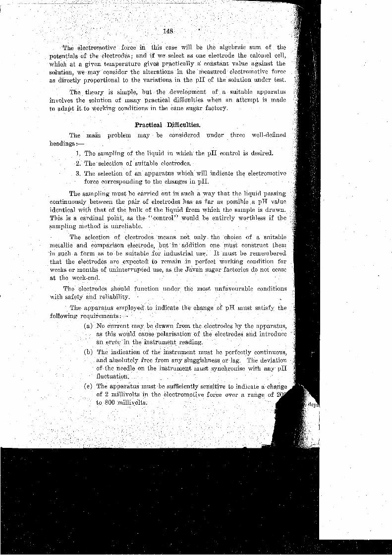
(a) No current may be drawn from the electrodes by the apparatus,as this would cause polarisation of the electrodes. and introducean error in· the' instrument reading.
(b) The indication of the instrument must be perfectly continuous,and absolutely free from any sluggishness or lag. The deviationof. the needle on the instrument must synchronise with any pIIfluctuation.
(c) The apparatus must be sufficiently sensitive to indicate a changeof 2 millivolts in the electromotive force over a range of 2to.·800 millivolts.

'; 149. '.:,:,.:,.,:.,:;:;.':;,:.,:',: ::<";'-'.:');.'",:::'"<:': ";:,.
(d) The construction of theappacatus .ml1stbeassimplea~I}Qssible,so that it may be adjusted or repaired with ease, while theequipment must be of robust build to .enable it to withstanddamage. due to mechanical shock.
It is not a difficult matter to fulfil all the, foregoing requirements whereone has access to modern items of equipment,and when these are operatedby competent persons in a laboratory, under moderate climatic conditions. Butif such fine and expensive equipment were placed in the hands of Javanese
.. workmen, in, a tropical country, with the expectation that it could be operated'without trouble, one is doomed to disappointment. The best way to determine
i the requirements of a suitable apparatus is to test available equipment andeliminate any weak points which are exposed by triaL
Practical Development.
In the screening of the film, the successive steps, are shown in the development of the apparatus at present employed..The method of employing indicatortest paper was purely intermittent, the operator knew nothing of what washappening between tests, nor was the speed of the pH change appreciated.The nature of the fluctuations which result with rthis method-of control areillustrated in Fig. 1.
'I'hause of indicators with the spot plate and colour charts provides amore sensitive test, and possesses an accuracyof 0.1-0.2 unit of pH, dependingon the nature of the test solution. But it suffers the same disability as thetest paper in that it provides only. for intermittent sampling, and the resultsobtained are little better than those fromthe test paper.
On the film is next seen the' first electrical apparatus, tested in 1930.The principles were formulated by Aten, but the apparatus depicted was themodification of van Oort. After much experimentation this outfit wasabandonedas-unsuitable, the principal reason being the rapid rate at whichtheplatinised electrode was poisoned', and, the difficulty of maintaining saturation ,of the test solution with hydrogen; the latter reduced the sampling rateto about 12 drops per minute.
. j'
T~e !lSm _gas type electrode was next tried. The. apparatus was constructed The:ding to Leeds and Northrup, and employed tungsten and calomelelectrod ructecemperature compensation was introduced by the employrnent ofa serie The)per-constantin couples. Although the results were. encouraging,many.1 thro~ies were encountered. Chief of these were the difficulty of prepari treealo;n electrodes, the necessity for maintaining a supply of potassiumehl 'he rate is in the porouscupof the calomel cell, due to their rapid solution
'tt h i toles, the complication introduced by the thermocompensator,and
ba
. atcl.ect "the apparatus to become choked with fine bagasse from the mixedy llsse - '.' '.. . . .

150r- --, 0..- i?
::::Ie::
C
.o:t::::-
or-
~i=
tI
I I ~=:;
! ----'-eb-"~
!. r-D....i-3-
I....;:::=.
fp.1-.- ~
...:; I,
..,1---
~
<--,-1-6
I ""~ -1;;2
,
!---'1-
n Ie·,u' I:::;>-
~
~P-
~ I1-:;"'"'-Ii?
i-=~--:
Ib-
1<:c::F' !
""r:- IA ;CS
~ i
2
4
5
7
6
3
::I:<:>c~
pH 7.0 8.0 9.0 ,10.0 IFIG. I.-Illustrating the value of the pH-meter on manualvIiming control : between', B
andC the test paper method was used,' between A and B, C and D, the operator foll~wed ,'themeter .reading. \

·:Alternative m:ethod~\ of sampling were then investigated; and ultimatelyifficulties were completelyovercome, Every portion of the flnal model
; 2) was readily accessible, and the electrodes were simply placed, in per~
Hons in an ebonite stopper, from which they were readily removable at
_±.IScm
+
Eu
~+1
FIG. 2.-Illustrating the flow cell with electrodes.
... It is necessary that the flow of juice through the sampler be maintained'p,ove a certain minimum volume per minute, depending upon the dimensionsf the apparatus used, as the potential of the antimony electrode is not constantelow this minimum rate of flow.
I
The electrodes employed consisted of a stick of antimony and a specially,onstructed calomel cell.
The saturated solution of potassium chloride is allowed to seep continufisly through the small plug of filter paper at the lower end of the syphon tube.f the \calomel cell (Fig. 2) thus preventing diffusion of the juice into the cell.he rate of flow is regulated by the elevation of the supply flask, which isttached to the cell by means of 'rubber tubing. The only attention requiredythisset-up is the occasional renewal of the paper plug.
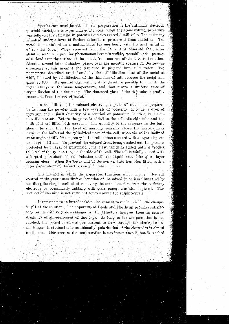
The method in which the, apparatus functions when employed for pHcontrol of the continuous first carbonation-of the mixed juice was illustrated bythe film; the simple method of removing the carbonate film from the. antimonyelectrode' by occasionally rubbing with glass paper, was also depicted. Thismethod of cleaning is not sufficient for removing the sulphite scale.
It remains now to introduce some instrument to render visible the changes. in pH of the solution. The apparatus of Leeds and Northrup provides satisfac
tory results with very slow changes in pH. ,It suffers, however, frOm the generaldisability of all equipment of this type. As long as the compensation is notreached, the potentiometer allows current to flow through the, electrodes; asthe balance is attained only occasionally, polarisation of the electrodes is almostcontinuous. Moreover, as the compensation is not instantaneous, but is reached
In the filling of the calomel .electrode, a paste of calomel is preparedby rubbing the powder with a few crystals of potassium chloride, a drop ofmercury, and a small quantity of' a solution of potassium chloride, in a non"metallic mortar. Before the paste is added to the cell, the side tube and thebulb of it are filled with mercury. The quantity of the mercury in the bulbshould be' such that the level of mercury remains above the narrow neckbetween the bulb and the cylindri.cal part of the cell, when the, cell is inclinedat an angle of 45°. The mercury in the cell is then covered with a layer of pasteto a depth of 3 mm. To prevent the calomel from being washed out, the paste isprotected bya layer of pulverised Jena glass, which is added, until it reaches.the level of the syphon tube on the side of the cell. The cell is finally rinsed withsaturated potassium'. chloride solution until the liquid above the glass layerremains clear. When the lower end of the syphon tube has been fitted with afilter paper stopper, the cell is ready for use.
152
Special care mustbetakenin the preparation of the antimony .electrodeto avoid variations between individual rods; when the standardized procedurewas followed the variation in potential did: not exceed 5 millivolts. The antimonyis melted under a layer of lithium chloride, to preserve it from oxidation. Themetal is maintained in a molten state for one hour, with frequent agitationof the test tube. When removed from the flame it is observed that, afterabout 20 seconds, ,a peculiar phenomenon becomes visible, resembling the passageof a cloud over the surface of the metal, from one end of the tube to the other.About a second later a shadow passes over the metallic surface in. the reversedirection; at this moment the test tube is 'plunged into cold: water. Thephenomena described are induced by the solidification first .of the metal at640°, followed by solidification of the thin film of salt between the metal andglass at 606°. By careful observation, it is therefore possible to quench themetal always at the same temperature" and thus ensure a tiniform state ofcrystallisation of the antimony. The shattered glass of the test tube is readilyremovable from the rod of metal.

~ressive steps, each ()ccupying 1-5-2 seconds,'ntially sluggish,andsometimes 20
~tc wide alterations in pH.
Meantime the trend of the pH may have been reversed', with the resultand rapid fluctuations in pH cannot be registered with this apparatus.
The recorder of Leeds and Northrup used in Java was illustrated on theTo avoid vibration in the factory, the equipment was mounted .on tennisThe recorder is, however, not sufficiently sensitive for. use with such
+
-?s .t;>"'Yi [[]
::F./""",,0 n -?s..f",f
,FIG. 3.-Showing the Wheatstone bridge arrangement for arnplifyingthe cell current.
rocesses as the sulphitation of mixed juice as frequently practised in Java.'11 apparatus was therefore constructed employing the principle' of the simple,lode valve as used in wireless equipment. When a given potential is applied,the grid' of such a valve, a definite current flows between the filament andate. If the antimony electrode be connected with the grid and the calomel cell
the filament, the fluctuations in the electromotive for~e corresponding to

- - - .. - ... - - . '1
I:CC M.E
_ 1&=+~rA\._\....;._-W·_~'
rn~-·!3tBV
.154
-ill]
o[j]J
.~
~ .~- 3o~ ~ t"O?.=ill
.\
T
95:e6V
6
m.AM '"-~~5t-'[E] --
FIG. 4.-Illustrating the instrument panel-upper side.
~~
~ I -<i>--f I. .~ I 4i-, ,+:-.; i-.,_._.. ,'+,
.-t.., .+ ,+,,' .-$-, '-$- I -e- ;.i . aim . . b • [!) . e ' : tL';' .... _. _. .. .. - --_ -_ .. - ---- ---- - ...... --_ .... _ .. -_ .. - ... -_._ ... -_ ... -
+-
!I
,. " , . - - ..- -- -." - . - - _.- ~ ",-- .. -
~:I
-e-
electrodes, while the grid of the second valve was connected permanently withits filament. The changes in current induced by the variations in pH werethen recorded by a milliammeter placed across the diagonal of the bridge. Thedetails of the construction will be evident from the accompanying diagrams.
(Figs. 3, 4, and 5.)
changes in pHofthe juice bring about an instantaneo~s and proportional changein the plate current of the valves, without any draught of current from theelectrodes. It remains now to present these variations in. visible .form,
A Wheatstone bridge ·arrangement was set up in which two of theordinary resistances were replaced by triode valves. To the grid of one ofthese were applied the impulses ,of; the electromotive force between the
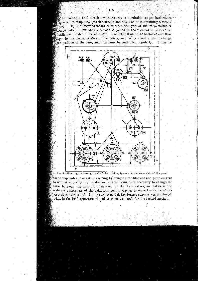
making a final decision with respect to a suitableached to simplicity Qf construction and the ease maintaining
point. By the latter is meant that; when the grid of the valve normallyected with the antimony electrode is joined to the filament of that valve,illiammeter should indicate zero. The exhaustion of the batteries and slow
"ges in the characteristics of the valves may bring about a slight changethe position of the zero, and this must be controlled regularly. It may be
r--- --_ .. -- ---- --------- .. --..-----~ ----- -----.::- --.--'- ...... '- .,. -.- ---;• I
"'1,III
iiIII
;I
'i,"
I'
j-{TII
,I
. ~ _. _'"':" - - . - _...,_ - - __ . 1
.... :
FIG. 5.-Showing the arrangement of electrical equipment on the lower side of the panel.
impossible to effect this setting by bringing the filament and plate currentto normal values by the resistances; in that event, it is necessary to change theratio between the internal resistance of the two valves, or between the
,ordinary resistances of the bridge, in such a way as to make the ratios of therespective pairs equal. In the earlier model,the former scheme was employed,while in the 1933 apparatus the adjustment was made by the second method.

156
An'interestil1gportion. of the film is that whie]; demonstrates the differencein operation of the pH-meter and the Leeds and Northrup recorder, whenoperating on the same solution (Fig. 13).
This may be effected simply by employing a stopper provided with 4holes,and supplied with the two pairs of electrodes. A milliammeter is alsoconnected in series in each apparatus to observe, whether any current is drawnfrom the electrodes by the instruments. If a sudden change in pH of thesolution is brought about, by the addition of an acid, the pH-meter will instantlyrecord the full pH change, whilst the recorder, after 2 seconds, begins to moveby small steps in the direction of increased acidity. The pH-meter indicates themaximum acidity attained by the'.solution, and thereafter gradually returns tothe normal pH value; the recorder, however, never attains the actual maximumvalue, and may indeed be travelling in the direction of increased acidity whenthe pH-meter is recording a change in the opposite sense. The lag ,pehindtheactual pH value is always evident.
That the recorder draws" current from the electrodes is also seen byobserving the milliammeter in the circuit. (Fig. 13.)
Fa,ctory Operation.
The next section of the film showed the operation of the apparatus inthe factory. The manner in which the continuous first and second carbonationof mixed or filtered juice is regulated with the aid of the pH-meter was illustrated. The workman experiences no difficulties in this regard-he has simplyto control the operation so as.to keep the pointer always on the predeterminedscale division. This is done by opening or closing the carbonic acid supply tothe juice container. In the discontinuous treatment '01 juice, such as, forinstance, with the sulphitation of mixed juices-the control is a little moredifficult. In this case, several large vessels each of 30 to 40 hectolitres capacityare used in rotation. The contents of 'each container are treated in sequence,and the process involves a wide change in pH, over the course of a few minutes.For such purposes the recorder is quite unsatisfactory, and the instantaneouspH-meter is necessary..• It. will beevident,also, that sampling difficulties are
.Jntrodueed where a; number of containers are in operation.
The process usually employed is that of adding the entire amount ofmilk, of lime to the .container at one time during the filling of the vessel.The lime is therefore confined chiefly 'to the juice in the lower portion of thecontainer. When the sulphurous acid gas is admitted, the thorough mixing ofth~, juice is. promoted,and the pointer on the pH-meter immediately rises topH 9.5. After mixing, the alkalinity is gradually reduced by the gas, andmay be followed readily on the meter. 'I'he workman shuts off the supplyprecisely at. the desired point-corresponding to say-pH 7·3.
A more recent method is. to inject the milk of lime into the juicemeans of compressed air; after the air has forced all' the lime into the. vessel,it acts .as a vigorous agitator and effects a thorough mixture.
6."
·i',,
J
rO.'p.m.
9.S?"",
'a.Sp,n"
pm:
65p.m
5.5p.m:
4:5p·m.
3~p.m.
2.5p.m.
1,5 p,m.
-
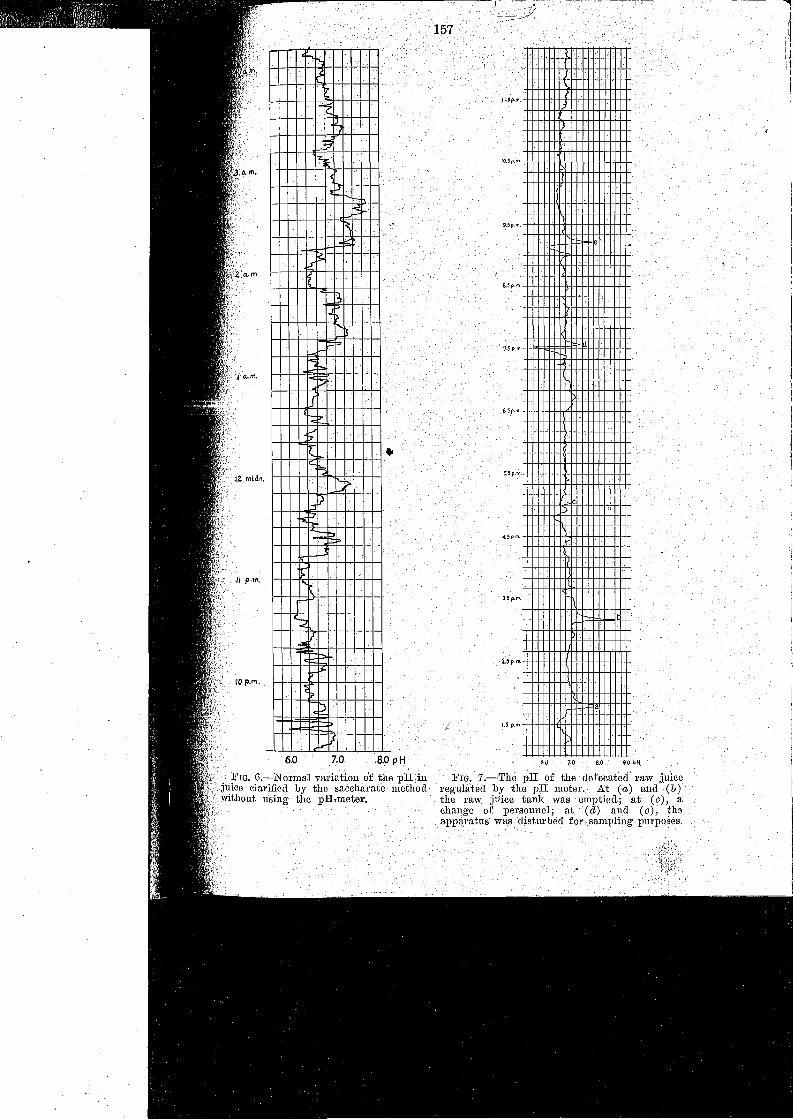
FIG, 7.--:-The pH of. the defecated raw juiceregulated by the pH meter. At (a.) and (b)the raw juice tank was, emptied; at (c), a:change. of personnel; at (d) and . (e) J theapparatus was disturbed for r sampling' purposes.
..
'<.,
,t
'"I?
L,
1
P~
:;;
~I:!" ,
~"
},
~~
I<:F:>
I<pr~
.-'
<,...
f=;
;:-
}
i"EfJ
1-- ~ ..
r
/
. P;J""IS'
?
VI}
6.0 7.0 8.0p H
. :FIG. G.-Normal variation of thep.Hdnjuice clarified by the aaceharate method
,:without using the pIf,meter.
158
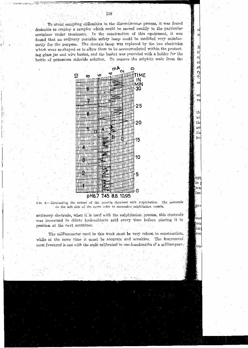
'I'oavoid sam.plingdifflculties in the discontinuous process, it was founddesirable to employ a sampler which could be moved readily to the particularcontainer under treatment. In. the construction of this equipment, it was.found that an ordinary portable safety lamp could be modified very satisfactorily for the purpose. The electric lamp was replaced by the two electrodeswhich were so shaped as to allow them to be accommodated within the protecting glass jar and wire basket, and the basket was provided with a holder for thebottle of potassium chloride solution. To remove the sulphite scale from the
er
I1
oo
t-. arn C\I --rrT1TIM E
INMIN30
FIG. 8.-Il1ustmting the nntura of the records obtained with sulphitation. The numeralson the left side of the curve refer to successive sulphitatlon vessels.
antimony electrode, when it..is used' with the sulphitation process, this electrodewas immersed in dilute hydrochloric acid every time before placing it inposition at the next container.
5
o
25
20
10
15
pH5.7 7.45 8.6 10.95
The milliammeter used in this work must be very robust in construction,while at the same time it must be accurate and :sensitive. The instrumentmost favoured is one with the scale calibrated in one-hundredths of a milliampere.
159
he employment ofa pH-scale'ii;l not necessary. T,he .inetrument: is'by the chemist for the particular environment, and' the workmans his control to the stipulated scale divisions.
inally, the method of applying recording pH control was demonstrated.'t possible simply to replace the milliammeter of the pR-Illeter by a record~trument, as the current across the bridge is altogether too weak to
:e it . It is necessary, in the fipst place, to a:p1plify the current by the aidwerful thermionic valve, which replaces the milliammeter in the Wheatridge circuit. The recorder is placed in the plate circuit of the amp li
valve,and the recording of the pH values then becomes a simple matter.:nly difficulty is that the amplifier requires a high current for the' filamentlate circuits.
The factory supply is generally used for the purpose, but as this istible to very great fluctuations, often exceeding 10 per cent. of the normalit is necessary to employ a voltage regulator in the circuit.
~. . ~
• The meter, the amplifier and the voltage stabilizer are placed ina case;ecording milliammeter and the sampler with the electrodes are connectedlhe balance of the equipment by the. cables, and placed in a position wheremay be used by the workman. When the latter is. operating with the
tance of the recorder, it is only necessary to trace on the chart straight'''"hich mark the permissible pH range, and the workman's objective is to',' the curve within these limits. '(Fig. 8.) ,
Discussion,
Dr. Harman,in reference t,o' a remark by Dr. Khainovsky that the:f1,ratus he had just described was capable of registering sudden changes,n of the juice, said that the recorder-controller described by Mr. Simmonssatisfactory for the purpose required of it., viz., control of pH in ordinary
2defecation, when such rapid changes of pH did not occur.
,', Mr. de Gyulay asked whether the reading on the milliammeter alwaysthe same pH value.
Dr. Khainovsky replied that they did not use a pH calibration-thereno temperature correction on the apparatus, although in one factory the
perature of the 'juice was observed to vary only ± 5°C. The J ava apparatusply records milliamperes, and the workmen are given some fixed limits to';kon.
Mr. Dick inquired whether the plug in the calomel half-cell was just aroll. He had used unglazed porcelain.

/JIrex CfasskJ,:r;g
Siowl to /'010/ Kef Boffle .
'>I ~~ }E
Y!f'Ml UIVphzziIlIlWlI7l21Mlnou,1IlItj1l1l/jJ),~Bake/,fe foyer
Dr. Khainovsky said that theyhad used porcelain, but this. could notbe renewed so readily. Th~y had large supplies of plugs of paper always onhand, and,. moreover, the plugs did not have to be changed very often.
Dr. Honig, in reply to Dr. Zerban, stated that the pH indicator was usedin all factories in ·Java.The electrode shown-in the film, however, had beenreplaced by another model, a sketch of which was as follows :_
'160
'"~~,
faloO?e l !lolftr)f
~ Sf> £/ec/rode
Dr. Micheli said; in regard to the antimony electrode, that the methodused during their work was to cast the' antimony in any suitable mould, place n,the casting ina bakelite sheath,and set it with pitch. The exposed surfacewas brightly polished. The theory regarding the functioning of the antimonyelectrode is that the E.M.F. depends on a layer of 8b
203on the metal surface.
It is thus needless to take elaborate precautions to prevent oxide formation,since a layer is formed instantaneously on exposure to' air.

'6 'DId
'8T 'DI.[
'91 'DI.[
'ot 'DI.[
'n 'DI.[

161
. Harman enquired whether the Ja#apparatusjust described .indicontrolled the pH .of the juice.
r..Honig replied that the apparatus was indicating only.
]Jr. Harman r:e~arked that their apparatus (as described by ]~I(r.
was comph;tely automatic-no manual control was necessary.
concluded the discussion, and the meeting adjourned.
DESCRIPTION OF PLATES OPPOSITE.
\.9.-Control as previously maintained. by test paper method.
t10.-Illustmtingthe calomel cell.11 AND 12.-SilOwingthe preparation of the ahtimony electrode: 11. 'I'esttube of
molten antimony removed from the :flame; 12. Plunged into a vessel of waterat the pl'ecisepoint of solidification.
Ii l.ik-'l:ne lower instrument on the left-hand side was placed in the p.H-meter cireuit ; nocurrent flowed when a change in the pH. occurred. The Instrument just abovewas placed in the Leeds Northrup circuit, and it will be observed that a definitecurrent is drawn from the cell when a change in pH takes place.
Illustrating manual control following the readings of the pH-meter.
,'15.-Showing the method employed in removing sulphite scale f'rom the calomel electrode. by immersing the assembly in diluteHCI.