Subsea Structures and Interfaces to Pipelines - Alvheim
19
Subsea Structures and Interfaces to Pipelines - Alvheim Dag Burgos Pipeline Design Supervisor Seminar Subsea Production Facilities Ingeniørenes Hus, 09.03.06
Transcript of Subsea Structures and Interfaces to Pipelines - Alvheim
Subsea Structures and Interfaces to Pipelines - Alvheim
Dag BurgosPipeline Design Supervisor
Seminar Subsea Production FacilitiesIngeniørenes Hus, 09.03.06

2
Agenda
Alvheim – General Project Data
Field Layout
Subsea Structures
EPCI scope
Layouts
Design Issues
Installation Issues
Questions

3
Alvheim – General Project Data
Client: Marathon Petroleum Company
Contract Value: 1 050 MNOK
Subsea Tie-back to FPSO “Odin”
Water Depth: 120 m
EPCI Contract:4 off Production Manifolds3 off Riser Bases incl. SSIVSage Tie-in skid75 km Sub sea pipelines ( from 4” to 14” )9 off Flexible Risers ( 10” – 12.5” ) 3 off dynamic Umbilical16 km Static Umbilical46 Spools ( diver tie-in )3 Riser Support systems (MWA)

4
Field Layout
WPS
Manifolds
Riser Bases
PLEM
SAGE skid

5
Alvheim Centre Layout

6
Description of Subsea Structures
4 Manifolds:• Boa• Kneler A• Kneler B• East Kameleon
Almost identical
Tie-in Skid at SAGE (Scotish Area Gas Evacuation)
3 Riser Bases:• East RB• West RB• South RB
Water Disposal PLEM

7
Main Subcontractors and Status
Manifolds
Riser Bases
Sage Skid
PLEM
Engineering
Genesis:Valves
CPI: Control system,
MPFM
Procurement
Other Components
NYMOGenesis
Fabrication
NYMO/MORSKA/Trelleborg
Installation
Technip
Ingenium
ABBREVIATIONS:
CPI = Company Provided ItemMPFM = Multi Phase Flow MeterPLEM = Pipeline End Manifold

8
Spools at manifolds
Manifold
Spools
Pipelines
4 trees
Spools
9
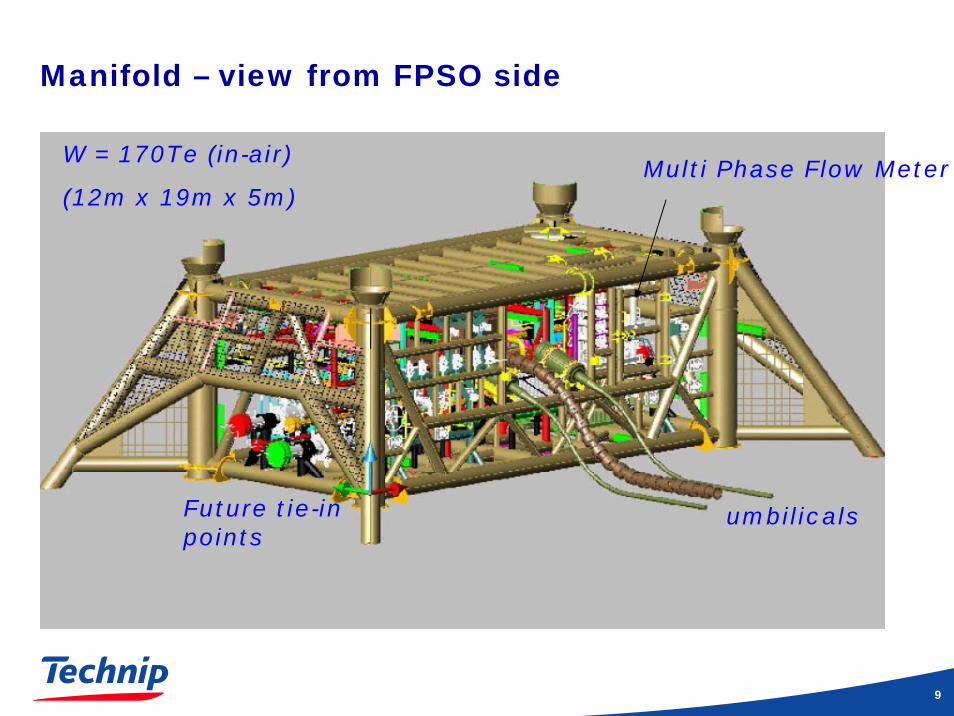
Manifold – view from FPSO side
W = 170Te (in-air)
(12m x 19m x 5m)
umbilicalsFuture tie-inpoints
Multi Phase Flow Meter

10
Manifold – Well side
Jumpersto treesTie-in points
Spools to trees
11
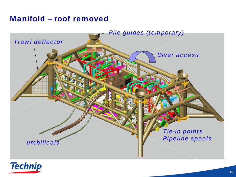
Manifold – roof removed
Diver access
umbilicals
Tie-in pointsPipeline spools
Trawl deflector
Pile guides (temporary)
12
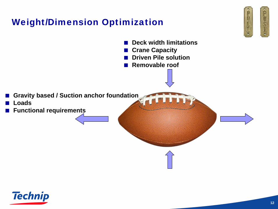
Weight/Dimension Optimization
Gravity based / Suction anchor foundationLoadsFunctional requirements
Deck width limitationsCrane CapacityDriven Pile solutionRemovable roof

13
Design Conditions - Structural
Load-out
Skidding (jacking)
Transportation
InstallationLifting (SIMO)Piling
In-placeOperational loadsTrawling loadsDropped objectSeismic
Crane
CSO Deep Pioneer
SA
CS
an
aly
se
s

14Title and date of the presentation
ALVHEIM DEVELOPMENT PROJECT Offshore Seminar – Subsea Structure Installation
Lift-off & Overboarding

15Title and date of the presentation
ALVHEIM DEVELOPMENT PROJECT Offshore Seminar – Subsea Structure Installation
Lifting Analysis with SIMO

16Title and date of the presentation
Piling OperationStructure with pile loading
hammer

17
Design Conditions - Piping
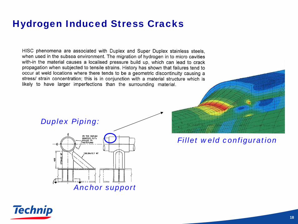
Design Pressure 200barDesign Temperature 65degSelfweightSpool tie-in loadsSpool operational loadsHydogen induced stress cracking
Supportreactions
Structural checkof supports andfoundation design
Caesar analysis
18
Hydrogen Induced Stress Cracks
Fillet weld configuration
Anchor support
Duplex Piping:


![37424265 Directed Studies Subsea Pipelines[1]](https://static.fdocuments.in/doc/165x107/544c8b3faf7959eb138b4638/37424265-directed-studies-subsea-pipelines1.jpg)