
Subsea Connectors and Cables
32
Subsea connectors and cable assemblies Dry-mate and wet-mate Burton™ subsea connectors
Transcript of Subsea Connectors and Cables
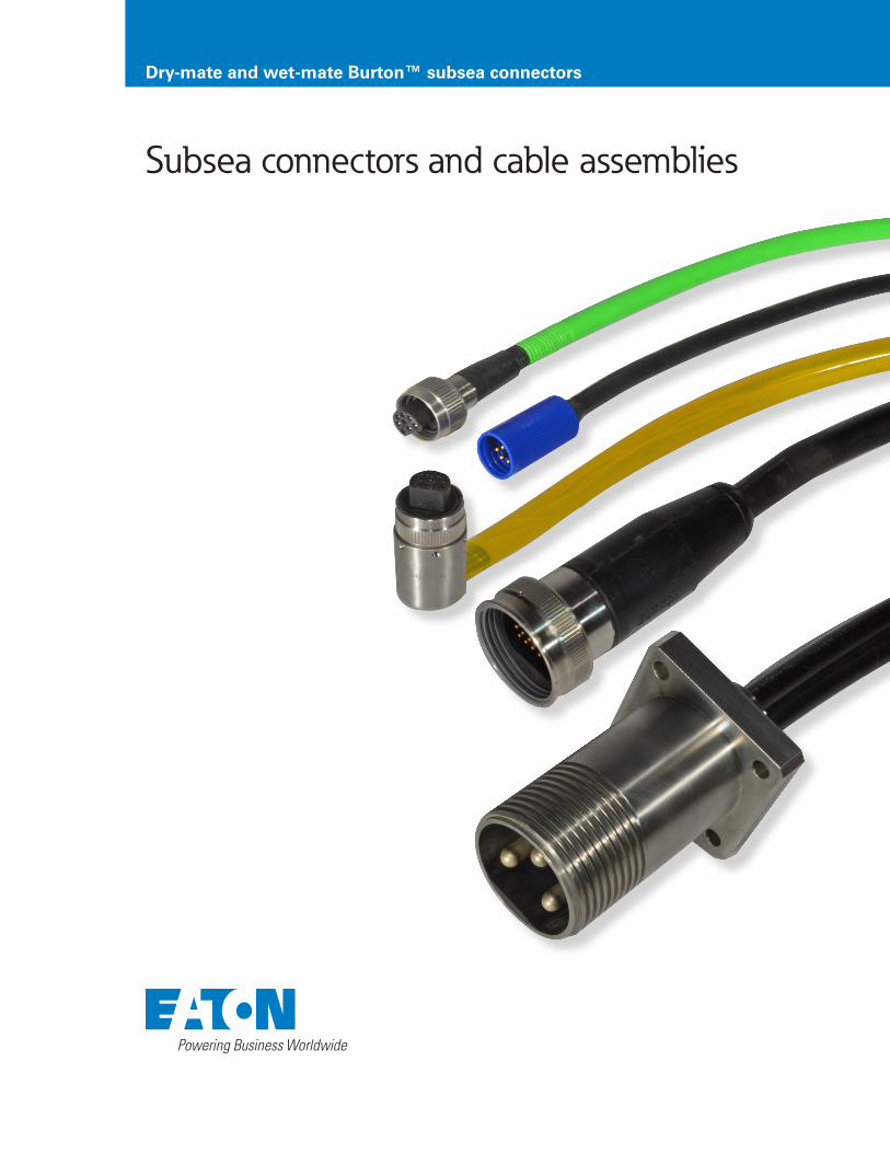
Subsea connectors and cable assemblies
Dry-mate and wet-mate Burton™ subsea connectors

Commercial and military subsea connectors and cable assemblies
Eaton’s 40-year track record of uncompromised reliability in subsea-connectivity applications includes Burton™ standard and custom solutions. This extensive commercial and military program heritage includes: • Remotely and autonomously operated vehicles and oceanographic-research instrumentation.
• Submarine launch-tube control and secondary propulsion, motor-control cable assemblies.
• Mine-detection-sled tow cables with integrated power-and-data connectivity and fuel delivery capabilities.
• Mine-hunting sonar, tether-cable assemblies.
Micro-Wet-Mate MCBH & MCIL Solutions
Micro-Dry-Mate Shell Sizes 9 & 12
Dry-Mate Shell Sizes 15 - 48
Overview 4
Part number configuration 6
Mechanical drawings 7
Locking sleeves 8
Installation instructions 9
Overview 10
Part number configuration 11
Mechanical drawings 12
Installation instructions 30
Overview 14
Part number configuration 16
High-voltage connectors 21
Mechanical drawings 24
Covers and dust caps 29
Installation instructions 31
2 EATON Subsea Connectors

Heritage-proven technologies accelerate custom-solution development
Eaton combines Burton™ standard-product technologies with advanced engineering tools and an extensive array of manufacturing resources to quickly deliver custom connectors and cable assemblies. Custom-solution capabilities include: • Application-specific shells, insert arrangements and EMI/RFI filtering and shielding for high currents and voltages, high-speed data, radio frequency and acoustic-signal applications.
• Harsh environments including extreme temperatures, shock, vibration, radiation, corrosive media, and pressures.
• Mechanical tow, fluid and gas delivery, and connector/cable separation and release.
This page describes just a few of the hundreds of custom solutions that comprise Eaton’s 40-year track record of uncompromised reliability. Please contact Eaton to discuss your application-specific requirements.
These custom connectors feature application-specific shells and inserts that support blind mating and staged engagements of signal, power and ground contacts.
Eaton developed custom shells and insert arrangements for this submarine control-cable application. NAVSEA S9320-AM-PRO-020 certified overmolding using clear polyurethane facilitates inspection of wiring terminations.
In addition to overmolded cables, quick-turn deliveries of bulkhead mounted and Pressure Balanced Oil Filled (PBOF) cable assemblies for Ethernet, signal and power applications are facilitated by Eaton’s broad range of wet and dry mate, standard products.
Custom penetrators are available to meet a broad array of mounting, environmental, voltage and current requirements.
3EATON Subsea Connectors

Micro-wet-mate connectors and cable assemblies
Eaton’s micro-wet-mate solutions incorporate rugged designs that provide 10,000 PSI pressure ratings and survive 1,000 mate and demate cycles.
These high-contact-density Burton™ connectors and cable assemblies are available in bulkhead, inline overmolded, and dummy-plug configurations: • Up to 8 contacts in 0.61” (15.5mm) diameter shells • Up to 16 contacts in 0.98” (25mm) diameter shells
Quick turn, application-specific-solution capabilities include: • High voltages and currents • High-speed-data including Ethernet • Harsh environments including extreme pressures, temperatures, mechanical stresses, and corrosive agents
Miniaturized solutions available with seven industry-standard contact arrangements
Gold plated, radiused pins resist corrosion and reduce mating forces
Radiused pin shoulders protect insulators from fraying
Reinforced neck resists damage during off-axis demating
Bulkhead connectors available in brass, stainless steel, aluminum, titanium and customer-defined materials
Integral threads facilitate rapid locking-sleeve installation (shell size M bulkhead connectors)
Color coded leads simplify conductor tracing
ShellDiameter
Number ofContacts
Max.Current
Max.Voltage
DielectricWithstand
InlineWire Sizes
BulkheadWire Sizes
0.61” (15.5mm)
3 7A 600V <10uA @ 2000VDC 18AWG 20AWG
4 7A 600V <10uA @ 2000VDC 18AWG 20AWG
5 3.5A 300V <10uA @ 1500VDC 20AWG 22AWG
6 3.5A 300V <10uA @ 1500VDC 20AWG 22AWG
8 3.5A 300V <10uA @ 1500VDC 20AWG 22AWG
0.98” (25.4mm)
10 3A 300V <10uA @ 1500VDC 20AWG 22AWG
16 2.5A 300V <10uA @ 1500VDC 20AWG 22AWG
4 EATON Subsea Connectors

High-contact-density power, signal and Ethernet solutions
Eaton’s comprehensive range of micro-wet-mate subsea solutions includes locking sleeves, dummy plugs and quick turn, custom-cable assemblies. Contact Eaton to discuss pressure balanced oil filled, wet-mate connectors.
Component Materials and Platings*
Bulkhead shellBrass (UNS C36000), Stainless Steel (UNS 31600/UNS 31603), Titanium (6AL/4V, UNS R56400), or Aluminum (6061-T6/T651, UNS A96061)
Body Proprietary neoprene blend
Contacts Gold-plated beryllium copper C173/C172 per ASTM B196
Orientation Pin 303/304 Stainless steel
Cable Jacketing Neoprene
Wire Insulation Bulkhead connectors: extruded TFE, inline configurations: EPDM
Locking Sleeves Delrin bodies and 302 stainless-steel snap rings
Dummy Plugs Proprietary neoprene blend
* Contact Eaton to discuss application-specific materials and platings
Parameter Ratings
Open face pressure 10,000 PSI
Mated pressure 10,000 PSI
Operating temperature -4°C to 60°C, 25°F to 140°F
Mating cycles 1000
Hi-pot voltage3 and 4 Contacts: 2000VDC
5 to 16 Contacts: 1500VDC
Insulation resistance > 200 Megaohms @ 1000 VDC
Rugged designs survive 1,000 mating cycles & 10,000 PSI open faced pressures
5EATON Subsea Connectors

Part number configuration – micro-wet-mate subsea connectors
B-MC BH 8 M - S 001
Type Shell Type
BH Bulkhead connector
DC Dummy connector
IL Inline connector with overmolded cable
Type Bulkhead Materials Type Bulkhead Materials
B Brass A Aluminum
S Stainless steel T Titanium
ConfigurationBulkhead Materials
Cable Length
Dummy Plugs Leave Blank Leave Blank
Bulkhead Receptacles
Select from Table Below
Standard: 001 (1 foot length) Optional: Enter any Whole Number up to 999
In-Line Enter a Zero Standard: 002 (2 Feet Length) Optional: Enter any Whole Number up to 999
Shell size A insert arrangements 0.98” (25mm) diameter shells
Depicted with male-pin connectors
Ten contacts Sixteen contacts
Burton™ Micro-Wet-Mate Connector
Shell Type (Table Below)
# of Contacts (Drawings Below)
Contact Type: M = Male Pin, F = Female Socket
Contact Eaton to Discuss Your Ethernet Requirements
Three contacts with alignment pin
Shell size M insert arrangements 0.61” (15.5mm) diameter shells
Depicted with male-pin connectors
Four contacts with alignment pin
Five contacts Six contacts Eight contacts
Connectors do not include locking sleeves, please refer to the table below for locking-sleeve ordering information
6 EATON Subsea Connectors

Mechanical drawings – micro-wet-mate subsea connectors
Shell Size M Shell Size A
A 1.32” (33.4mm) 1.99” (50.5mm)
B 1.55” (39.4mm) 2.37” (60.2mm)
øC 0.61” (15.5mm) 0.98” (25.4mm)
0.32”(8.13 mm)
0.32”(8.13 mm)
0.56”(14.2 mm)
0.75”(19.0 mm)
0.75”(19 mm)
A B
1.85”(47.0 mm)
0.75” (19.0 mm)
1.65”(41.9 mm)
1.10”(27.9 mm)
0.75”(19 mm)
0.75”(19.0 mm)
0.81”(20.6 mm)
0.81”(20.6 mm)
ø1.00”(25.4 mm)
0.75”(19 mm)
7/16-20UNF-2A
1/2-20UNF-2A 1/2-20UNF-2A
7/16-20UNF-2ALocking-sleeve threads
øC
Shell size M bulkhead connectors
Shell size A bulkhead connectors
Inline connectors
Male contacts Female contacts
7EATON Subsea Connectors

1.63”(41.40 mm)
1.29”(32.77 mm)
1.45”(36.83 mm)
0.88”(22.35mm)
ø0.86”(21.84 mm)
ø1.29”(32.77 mm)
ø0.86”(21.84 mm)
ø1.33”(33.78 mm)
Mechanical drawings – micro-wet-mate locking sleeves
Shell size M (3 to 8 contacts) locking sleeves
Shell size A (10 and 16 contacts) locking sleeves
B-MCDLSF Used with connectors with socket contacts
B-DLSAF Used with connectors with socket contacts
B-MCDLSM Used with connectors with pin contacts
B-DLSAM Used with connectors with pin contacts
8 EATON Subsea Connectors

Installation instructions – micro-wet-mate subsea connectors
Greasing and Mating
Above Water Mating Submerged Mating in Depths Less Than Three Meters
Apply a silicone grease, such as Molykote 44 Medium, to approximately 10% of the depth of the female contact socket cavities.
Apply a silicone grease, such as Molykote 44 Medium, to approximately 30% of the depth of the female contact socket cavities.
Confirm that the openings of all female sockets are sealed with grease and that a thin layer of grease covers the face of the female-contact connector.
Mate and demate the connector and inspect for grease on all male contacts before final remating.
Fully mate the connector and remove excess grease.
Mate and demate by pushing straight in and pulling straight out and never at an angle. Always grasp the connector body and never try to demate by pulling on the cable.
Repeat these processes using new grease whenever male and female connectors are demated and remated.
Wiring Color Codes
Contact # Wire Color Contact # Wire Color Contact # Wire Color
1 Black 7 White & Black 13 Red & White
2 White 8 Red & Black 14 Green & White
3* Red 9 Green & Black 15 Blue & White
4 Green 10 Orange & Black 16 Black & Red
5 Orange 11 Blue & Black
6 Blue 12 Black & White
* Three-pin connectors utilize a green wire on pin #3.
9EATON Subsea Connectors

Eaton’s high contact density, shell size 9 and 12 dry-mate connectors are available with 6, 8, and 14 contacts; custom contact arrangements are also available. Additional features include:
• 10,000 PSI open-faced pressure ratings • Gold plated, copper-alloy contacts • Standard 600-volt dielectric ratings • Cable assemblies available in overmolded and Pressure Balanced Oil Filled (PBOF) configurations.
• Contact Eaton to discuss solutions for Ethernet and high-voltage applications.
Compared to shell size 20 connectors, shell sizes 9 and 12 provide space savings of 58% and 40%, respectively.
Quick-turn, custom-cable capabilities include Pressure Balanced Oil Filled (PBOF) solutions.
10,000 PSI open-faced pressure ratings
Passivated 316 stainless steel shells and coupling rings. Titanium, Monel, and other materials available upon request.
Integrally-molded interfacial seals eliminate failures caused by O-ring loss or damage
Connectors available with in-line and
right-angle cable attachments.
Micro-dry-mate subsea connectors – shell sizes 9 and 12
Materials and Finishes
Contacts / Inserts Gold plated, copper alloy / Proprietary neoprene compounds
Shells and coupling rings Passivated 316 stainless steel, other materials available upon request
Overmold Neoprene, other materials available upon request
Cable / Pigtails UL SOW-A or MIL-C-915 / NEMA HP3, SAE-AS22759
Performance and Environmental
Pressure rating 10,000 PSI open faced pressure rating, standard, Contact Eaton to discuss application-specific pressure requirements
Mating cycles Rated for 500 mate/demate cycles
Operating temperature range - 40 to 90˚C, - 40 to 194˚F
Operating voltage ratings 600V standard; contact Eaton to discuss high-voltage configurations
High-contact-density solutions for subsea Ethernet, signal and power applications
10 EATON Subsea Connectors
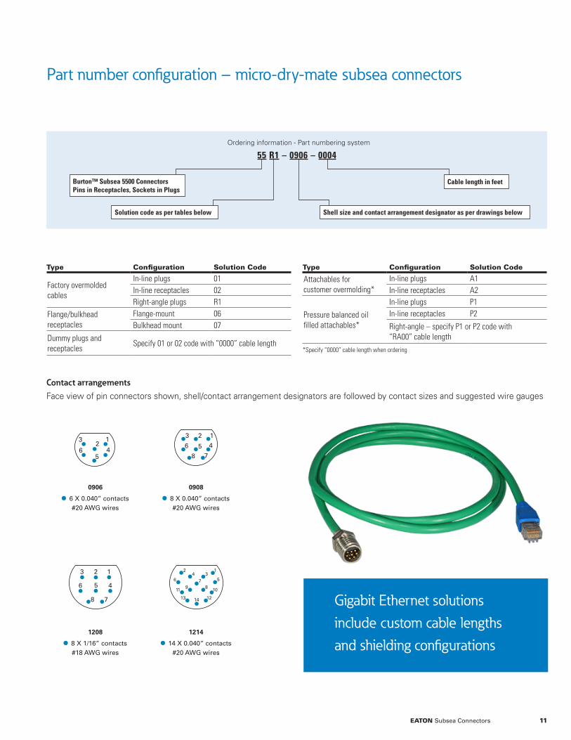
Part number configuration – micro-dry-mate subsea connectors
Ordering information - Part numbering system
55 R1 – 0906 – 0004
Solution code as per tables below
Cable length in feet
Shell size and contact arrangement designator as per drawings below
Burton™ Subsea 5500 ConnectorsPins in Receptacles, Sockets in Plugs
Type Configuration Solution Code
Factory overmolded cables
In-line plugs 01In-line receptacles 02Right-angle plugs R1
Flange/bulkheadreceptacles
Flange-mount 06Bulkhead mount 07
Dummy plugs and receptacles
Specify 01 or 02 code with “0000” cable length
Type Configuration Solution Code
Attachables for customer overmolding*
In-line plugs A1In-line receptacles A2
Pressure balanced oilfilled attachables*
In-line plugs P1In-line receptacles P2
Right-angle – specify P1 or P2 code with “RA00” cable length
*Specify “0000” cable length when ordering
Contact arrangements
Face view of pin connectors shown, shell/contact arrangement designators are followed by contact sizes and suggested wire gauges
Gigabit Ethernet solutions include custom cable lengths and shielding configurations
09080906
1208 1214
Page 11mm size relative
23 1
4578
61
23
45
6
123
45
78
6
1234
576
10 8911
121413
09080906
1208 1214
Page 11mm size relative
23 1
4578
61
23
45
6
123
45
78
6
1234
576
10 8911
121413
0906
• 6 X 0.040” contacts#20 AWG wires
0908
• 8 X 0.040” contacts#20 AWG wires
1208
• 8 X 1/16” contacts#18 AWG wires
1214
• 14 X 0.040” contacts#20 AWG wires
11EATON Subsea Connectors

Mechanical drawings – micro-dry-mate subsea connectors
Ø0.65”/ 0.91”(16.50 / 23.10mm)
Ø0.65”/ 0.91”(16.50 / 23.10mm)
Ø0.65”/ 0.91”(16.50 / 23.10 mm)
4X Ø0.13”/ 0.15”(3.30 / 3.80mm)
0.56”/ 0.88”(14.20 / 22.40 mm)
0.33”/ 0.50”(8.38 / 12.70 mm)
Ø0.50”/ 0.63”(12.70 / 16.00mm)
1.76”/ 2.18”(44.70 / 55.40mm)
In-Line Receptacles Bulkhead Receptacles Flange-Mount Receptacles
Attachable PlugsIn-Line Plugs Right-Angle Plugs
0.95”/ 1.55”(24.10 / 39.40mm)
1.67”/ 2.23”(42.40 / 56.60 mm)
0.63”/ 0.75”(15.90 / 19.00mm)
Ø0.44”/ 0.63”(11.20 / 16.00mm)
0.75”/ 1.33”(19.00 / 33.78 mm)
1.97”/ 2.43”(50.00 / 61.70mm)
1.05”/ 1.40”(26.70 / 35.60 mm)
0.88”/ 1.06”(22.40 / 26.90mm)
1.05”/ 1.20”(26.70 / 30.50mm)
0.30”/ 0.30”(7.60 / 7.60mm)
0.75”/ 0.90”(19.00 / 22.90mm)
A-Thread
A-Thread
A-Thread
B-Thread O-Ring SealØ0.65”/ 0.91”(16.50 / 23.10mm)
Ø0.65”/ 0.91”(16.50 / 23.10mm)
Ø0.65”/ 0.91”(16.50 / 23.10 mm)
4X Ø0.13”/ 0.15”(3.30 / 3.80mm)
0.56”/ 0.88”(14.20 / 22.40 mm)
0.33”/ 0.50”(8.38 / 12.70 mm)
Ø0.50”/ 0.63”(12.70 / 16.00mm)
1.76”/ 2.18”(44.70 / 55.40mm)
In-Line Receptacles Bulkhead Receptacles Flange-Mount Receptacles
Attachable PlugsIn-Line Plugs Right-Angle Plugs
0.95”/ 1.55”(24.10 / 39.40mm)
1.67”/ 2.23”(42.40 / 56.60 mm)
0.63”/ 0.75”(15.90 / 19.00mm)
Ø0.44”/ 0.63”(11.20 / 16.00mm)
0.75”/ 1.33”(19.00 / 33.78 mm)
1.97”/ 2.43”(50.00 / 61.70mm)
1.05”/ 1.40”(26.70 / 35.60 mm)
0.88”/ 1.06”(22.40 / 26.90mm)
1.05”/ 1.20”(26.70 / 30.50mm)
0.30”/ 0.30”(7.60 / 7.60mm)
0.75”/ 0.90”(19.00 / 22.90mm)
A-Thread
A-Thread
A-Thread
B-Thread O-Ring Seal
Ø0.65”/ 0.91”(16.50 / 23.10mm)
Ø0.65”/ 0.91”(16.50 / 23.10mm)
Ø0.65”/ 0.91”(16.50 / 23.10 mm)
4X Ø0.13”/ 0.15”(3.30 / 3.80mm)
0.56”/ 0.88”(14.20 / 22.40 mm)
0.33”/ 0.50”(8.38 / 12.70 mm)
Ø0.50”/ 0.63”(12.70 / 16.00mm)
1.76”/ 2.18”(44.70 / 55.40mm)
In-Line Receptacles Bulkhead Receptacles Flange-Mount Receptacles
Attachable PlugsIn-Line Plugs Right-Angle Plugs
0.95”/ 1.55”(24.10 / 39.40mm)
1.67”/ 2.23”(42.40 / 56.60 mm)
0.63”/ 0.75”(15.90 / 19.00mm)
Ø0.44”/ 0.63”(11.20 / 16.00mm)
0.75”/ 1.33”(19.00 / 33.78 mm)
1.97”/ 2.43”(50.00 / 61.70mm)
1.05”/ 1.40”(26.70 / 35.60 mm)
0.88”/ 1.06”(22.40 / 26.90mm)
1.05”/ 1.20”(26.70 / 30.50mm)
0.30”/ 0.30”(7.60 / 7.60mm)
0.75”/ 0.90”(19.00 / 22.90mm)
A-Thread
A-Thread
A-Thread
B-Thread O-Ring Seal
In-Line Plugs
Right-Angle Plugs
Bulkhead Receptacles
Attachable Plugs
In-Line Receptacles
Dimensions are stated as shell size 9 / shell size 12
Shell A-Thread B-Thread
09 9/16 – 12 Stub Acme 3/8 -24 UNF-2A
12 ¾ - 12 Stub Acme 9/16-18 UNF
Thread Information
12 EATON Subsea Connectors

Mechanical drawings – micro-dry-mate subsea connectors (continued)Ø0.65”/ 0.91”
(16.50 / 23.10mm)Ø0.65”/ 0.91”
(16.50 / 23.10mm)Ø0.65”/ 0.91”
(16.50 / 23.10 mm)
4X Ø0.13”/ 0.15”(3.30 / 3.80mm)
0.56”/ 0.88”(14.20 / 22.40 mm)
0.33”/ 0.50”(8.38 / 12.70 mm)
Ø0.50”/ 0.63”(12.70 / 16.00mm)
1.76”/ 2.18”(44.70 / 55.40mm)
In-Line Receptacles Bulkhead Receptacles Flange-Mount Receptacles
Attachable PlugsIn-Line Plugs Right-Angle Plugs
0.95”/ 1.55”(24.10 / 39.40mm)
1.67”/ 2.23”(42.40 / 56.60 mm)
0.63”/ 0.75”(15.90 / 19.00mm)
Ø0.44”/ 0.63”(11.20 / 16.00mm)
0.75”/ 1.33”(19.00 / 33.78 mm)
1.97”/ 2.43”(50.00 / 61.70mm)
1.05”/ 1.40”(26.70 / 35.60 mm)
0.88”/ 1.06”(22.40 / 26.90mm)
1.05”/ 1.20”(26.70 / 30.50mm)
0.30”/ 0.30”(7.60 / 7.60mm)
0.75”/ 0.90”(19.00 / 22.90mm)
A-Thread
A-Thread
A-Thread
B-Thread O-Ring Seal
3.81”(96.8mm)
Shell Size 12 Pressure Balanced Oil Filled
Ø0.91”(23.1mm)
Ø0.67” (17.0mm)
2.29”(58.2mm)
Shell Size 9 Pressure Balanced Oil Filled
Ø0.65”(16.5 mm)
Ø0.40”(10.2 mm)
Flange-Mount Receptacles
Shell Size 9 Pressure Balanced Oil Filled
Shell Size 12 Pressure Balanced Oil Filled
Dimensions are stated as shell size 9 / shell size 12
13EATON Subsea Connectors

Dry-mate subsea connectors – shell sizes 15 to 48
Eaton’s subsea solutions include Burton™ dry-mate connectors in shell sizes 15 to 48. These 10,000 PSI-rated interconnects have been field proven for over 40 years and feature integrally molded interfacial seals that, unlike O-rings, cannot fall off.
Additional harsh-environment design features include: • Stub ACME threads (size 16 and larger shells) provide protection against cross threading and damage.
• Factory-overmolded solutions feature crimped contacts that are more resistant to damage from flexing than soldered terminals.
• High-temperature overmolding is performed under several thousand pounds of pressure to ensure a robust bond that eliminates water intrusion.
Dry-Mate Connectors Overview - Shell Sizes 15 to 48
Plug configurations• In-line and right angle, factory-overmolded cable assemblies• Pressure Balanced Oil Filled (PBOF), shell sizes 15 to 32• Attachable, in-line solutions for customer overmolding
Receptacle configurations• Square flange and bulkhead-mount configurations•Attachable, in-line solutions for customer overmolding
Contacts and terminations• Pins in receptacles, sockets in plugs (5500 connectors)• Pins in plugs, sockets in receptacles (6600 connectors)• Factory-overmolded solutions utilize crimped terminations, attachable and PBOF connectors utilize soldered terminations
Ethernet solutions• Standard Ethernet/power and pure Ethernet cables in shell sizes 15 and 20 rated for 1 Gb/sec. up to 75 meters cable length• Contact Eaton to discuss application-specific Ethernet solutions in other shell sizes
End-to-end solutions include factory overmolded and Pressure Balanced Oil Filled (PBOF) cable assemblies for Ethernet, signal, power and hybrid applications.
The overmolded solution depicted to the left features abrasion-resistant jacketing and anti-capillary water blocking.
Eaton offers a broad range of custom solutions. This cable assembly features NAVSEA-PRO-20 certified polyurethane overmolding, shielded twisted pairs, and a 1000V rating.
14 EATON Subsea Connectors

Solutions include Ethernet and high-voltage cable assemblies
Materials and Finishes
Contacts Gold plated, copper alloy
Inserts Proprietary neoprene compounds
Shells and coupling rings Passivated 316 stainless steel, other materials available upon request
Overmold Neoprene, other materials available upon request
Cable UL SOW-A or MIL-C-915
Pigtails MIL-W-16878
Performance and Environmental
Pressure rating 10,000 PSI open faced pressure rating standard. Contact Eaton to discuss application-specific pressure requirements
Mating cycles Rated for 500 mate/demate cycles
Operating-temperature range - 40 to 90˚C, - 40 to 194˚F
Operating-voltage ratings• 600V ratings standard on all contact arrangements• 1000V to 5000V ratings available on selected contact arrangements. Please refer to page 21 for additional information
Eaton offers the industry’s broadest range of dry-mate solutions with integrally-molded interfacial seals; eliminating failures caused by O-ring loss or damage
15EATON Subsea Connectors
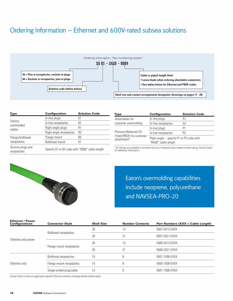
Ordering information – Ethernet and 600V-rated subsea solutions
Ordering information - Part numbering system
55 01 – 2420 – 0004
Solution code (tables below)
Cable or pigtail length (feet)
• Leave blank when ordering attachable connectors
• See tables below for Ethernet and PBOF codes
Shell size and contact arrangements designator (drawings on pages 17 - 20)
55 = Pins in receptacles, sockets in plugs
66 = Sockets in receptacles, pins in plugs
Type Configuration Solution Code
Factory overmolded cables
In-line plugs 01In-line receptacles 02Right-angle plugs R1Right-angle receptacles R2
Flange/bulkheadreceptacles
Flange mount 06Bulkhead mount 07
Dummy plugs and receptacles
Specify 01 or 02 code with “0000” cable length
Ethernet / Power Configurations Connector Style Shell Size Number Contacts Part Numbers (XXX = Cable Length)
Ethernet and power
Bulkhead receptacles20 13 5507-2013-EXXX
20 21 5507-2021-EXXX
Flange mount receptacles20 13 5506-2013-EXXX
20 21 5506-2021-EXXX
Ethernet only
Bulkhead receptacles 15 8 5507-1508-EXXX
Flange mount receptacles 15 8 5506-1508-EXXX
Single ended plug/cable 15 8 5501-1508-EXXX
Contact Eaton to discuss application-specific Ethernet solutions including double-ended cables.
Type Configuration Solution Code
Attachables for customer overmolding
In-line plugs A1In-line receptacles A2
Pressure Balanced OilFilled (PBOF) for customer attachment*
In-line plugs P1In-line receptacles P2
Right-angle – specify P1 or P2 code with “RA00” cable length
*JIC fittings are available to facilitate the use of hydraulic hose instead of clear tubing. Contact Eaton for additional information.
Eaton’s overmolding capabilities include neoprene, polyurethane and NAVSEA-PRO-20
16 EATON Subsea Connectors

Contact arrangements – dry-mate 5500 subsea connectorsFace view of pin connectors shown, insert arrangement designators are followed by contact sizes and suggested wire gauges
123
45
78
6
123
46
512
3 4
12
3
123
45
78
6
123
46
512
34
12
3
123
45
78
6
123
46
512
34
1 2
3
12345
6789
1011121314
15161718
192021
1234
56789
10111213
4567
8910
123
1
23
12
354
768
1503 1504 1506 1508
1603 1604 1606 1608
1610 2003 2004 2006 2008
20A8 20B3
Page 17mm size relative
2013 2021
123
45
78
6
123
46
512
3 4
12
3
123
45
78
6
123
46
512
34
12
3
123
45
78
6
123
46
512
34
1 2
3
12345
6789
1011121314
15161718
192021
1234
56789
10111213
4567
8910
123
1
23
12
354
768
1503 1504 1506 1508
1603 1604 1606 1608
1610 2003 2004 2006 2008
20A8 20B3
Page 17mm size relative
2013 2021
123
45
78
6
123
46
512
3 4
12
3
123
45
78
6
123
46
512
34
12
3
123
45
78
6
123
46
512
34
1 2
3
12345
6789
1011121314
15161718
192021
1234
56789
10111213
4567
8910
123
1
23
12
354
768
1503 1504 1506 1508
1603 1604 1606 1608
1610 2003 2004 2006 2008
20A8 20B3
Page 17mm size relative
2013 2021
123
45
78
6
123
46
512
3 4
12
3
123
45
78
6
123
46
512
34
12
3
123
45
78
6
123
46
512
34
1 2
3
12345
6789
1011121314
15161718
192021
1234
56789
10111213
4567
8910
123
1
23
12
354
768
1503 1504 1506 1508
1603 1604 1606 1608
1610 2003 2004 2006 2008
20A8 20B3
Page 17mm size relative
2013 2021
1503
• 2 X 3/32” contacts#16 AWG wires
1504
• 4 X 1/16” contacts#18 AWG wires
1506
• 6 X 1/16” contacts#18 AWG wires
1508
• 8 X 1/16” contacts#18 AWG wires
20A8
• 8 X 3/32” contacts#16 AWG wires
20B3
• 3 X 1/8” contacts#16 AWG wires
2013
• 13 X 1/16” contacts#18 AWG wires
2021
• 21 X 1/16” contacts#18 AWG wires
1610
• 10 X 1/16” contacts#18 AWG wires
2003
• 3 X 1/8” contacts#16 AWG wires
2004
• 4 X 1/8” contacts#16 AWG wires
2006
• 6 X 1/8” contacts#16 AWG wires
2008
• 8 X 3/32” contacts#16 AWG wires
1603
• 3 X 3/32” contacts#16 AWG wires
1604
• 4 X 1/16” contacts#18 AWG wires
1606
• 6 X 1/16” contacts#18 AWG wires
1608
• 8 X 1/16” contacts#18 AWG wires
17EATON Subsea Connectors

Contact arrangements – dry-mate 5500 subsea connectorsFace view of pin connectors shown, insert arrangement designators are followed by contact sizes and suggested wire gauges
15 16 20 2432
2 3
1
4
12
3
123
6457
9810
1112
123
4567
8910
1234
891011
56
12
7
1312141516
123
891011
4567
12345
12131415
17181920
16
67891011
56789
192021
15161718
1234
1011121314
56789
1617181920
212324
22
1234
10111213141520212223242526
141516171819
2728293031323334353637
3839
78910111213123456
13
456
2
7
8910
78
456
123
2410
1
3
2
2403 2412 2420 3203
3204 3208 3210 3212 3216
3221 3224 3239
Page 18
mm size relative 15 16 20 2432
2 3
1
4
12
3
123
6457
9810
1112
123
4567
8910
1234
891011
56
12
7
1312141516
123
891011
4567
12345
12131415
17181920
16
67891011
56789
192021
15161718
1234
1011121314
56789
1617181920
212324
22
1234
10111213141520212223242526
141516171819
2728293031323334353637
3839
78910111213123456
13
456
2
7
8910
78
456
123
2410
1
3
2
2403 2412 2420 3203
3204 3208 3210 3212 3216
3221 3224 3239
Page 18
mm size relative
15 16 20 2432
2 3
1
4
12
3
123
6457
9810
1112
123
4567
8910
1234
891011
56
12
7
1312141516
123
891011
4567
12345
12131415
17181920
16
67891011
56789
192021
15161718
1234
1011121314
56789
1617181920
212324
22
1234
10111213141520212223242526
141516171819
2728293031323334353637
3839
78910111213123456
13
456
2
7
8910
78
456
123
2410
1
3
2
2403 2412 2420 3203
3204 3208 3210 3212 3216
3221 3224 3239
Page 18
mm size relative
2403
• 3 X 3/32” contacts#16 AWG wires
2410
• 8 X 1/8” contacts
• 2 X 3/32” contacts#16 AWG wires
2412
• 12 X 3/32” contacts#16 AWG wires
2420
• 20 X 1/16” contacts#18 AWG wires
3203
• 3 X 3/16” contacts#8 AWG wires
3221
• 9 X 3/32” contacts
• 8 X 1/8” contacts
• 4 X 5/32” contacts#16 AWG wires
3224
• 18 X 3/32” contacts
• 6 X 1/8” contacts#16 AWG wires
3239
• 39 X 1/16” contacts#18 AWG wires
3204
• 4 X 3/16” contacts#8 AWG wires
3208
• 4 X 3/32” contacts
• 4 X 3/16” contacts#16 & #8 AWG wires
3210
• 10 X 5/32” contacts#16 AWG wires
3212
• 12 X 5/32” contacts#16 AWG wires
3216
• 11 X 3/32” contacts
• 5 X 1/8” contacts#16 AWG wires
15 16 20 2432
2 3
1
4
12
3
123
6457
9810
1112
123
4567
8910
1234
891011
56
12
7
1312141516
123
891011
4567
12345
12131415
17181920
16
67891011
56789
192021
15161718
1234
1011121314
56789
1617181920
212324
22
1234
10111213141520212223242526
141516171819
2728293031323334353637
3839
78910111213123456
13
456
2
7
8910
78
456
123
2410
1
3
2
2403 2412 2420 3203
3204 3208 3210 3212 3216
3221 3224 3239
Page 18
mm size relative
15 16 20 2432
2 3
1
4
12
3
123
6457
9810
1112
123
4567
8910
1234
891011
56
12
7
1312141516
123
891011
4567
12345
12131415
17181920
16
67891011
56789
192021
15161718
1234
1011121314
56789
1617181920
212324
22
1234
10111213141520212223242526
141516171819
2728293031323334353637
3839
78910111213123456
13
456
2
7
8910
78
456
123
2410
1
3
2
2403 2412 2420 3203
3204 3208 3210 3212 3216
3221 3224 3239
Page 18
mm size relative15 16 20 24
32
2 3
1
4
12
3
123
6457
9810
1112
123
4567
8910
1234
891011
56
12
7
1312141516
123
891011
4567
12345
12131415
17181920
16
67891011
56789
192021
15161718
1234
1011121314
56789
1617181920
212324
22
1234
10111213141520212223242526
141516171819
2728293031323334353637
3839
78910111213123456
13
456
2
7
8910
78
456
123
2410
1
3
2
2403 2412 2420 3203
3204 3208 3210 3212 3216
3221 3224 3239
Page 18
mm size relative
18 EATON Subsea Connectors

Contact arrangements – dry-mate 6600 subsea connectorsFace view of pin connectors shown, insert arrangement designators are followed by contact sizes and suggested wire gauges
1603 16081604 1606
2006 2008 2013 2404
2408 2412 2420
Page 19
123
45
78
6
123
46
512
34
12
3
123
45
78
6
123
46
5
2004
12
34
12
34
2403 2406
12
56
34
12
67
35
8
43
12345
12 1314151617181920
67891011
2410
12
564
7910
8
2003
12
3
12
3
1234
56789
10111213
123
6457
9810
1112
1603 16081604 1606
2006 2008 2013 2404
2408 2412 2420
Page 19
123
45
78
6
123
46
512
34
12
3
123
45
78
6
123
46
5
2004
12
34
12
34
2403 2406
12
56
34
12
67
35
8
43
12345
12 1314151617181920
67891011
2410
12
564
7910
8
2003
12
3
12
3
1234
56789
10111213
123
6457
9810
1112
1603 16081604 1606
2006 2008 2013 2404
2408 2412 2420
Page 19
123
45
78
6
123
46
512
34
12
3
123
45
78
6
123
46
5
2004
12
34
12
34
2403 2406
12
56
34
12
67
35
8
43
12345
12 1314151617181920
67891011
2410
12
564
7910
8
2003
12
3
12
3
1234
56789
10111213
123
6457
9810
1112
1604
• 4 X 1/16” contacts#18 AWG wires
2008
• 8 X 1/16” contacts#18 AWG wires
1603
• 3 X 3/32” contacts#16 AWG wires
2006
• 6 X 1/16” contacts#18 AWG wires
1606
• 6 X 1/16” contacts#18 AWG wires
2013
• 13 X 1/16” contacts#18 AWG wires
1608
• 8 X 1/16” contacts#18 AWG wires
2403
• 3 X 3/32” contacts#16 AWG wires
2003
• 3 X 1/8” contacts#16 AWG wires
2404
• 4 X 5/32” contacts#12 AWG wires
2004
• 2 X 1/8” contacts
• 2 X 5/32 contact#16 AWG wires
2406
• 4 X 1/8” contacts
• 2 X 5/32” contacts#16 AWG wires
2408
• 2 X 3/32” contacts
• 6 X 1/8” contacts#16 AWG wires
2410
• 10 X 3/32” contacts#16 AWG wires
2412
• 12 X 3/32” contacts#16 AWG wires
2420
• 20 X 1/16” contacts#18 AWG wires
15 16 20 2432
2 3
1
4
12
3
123
6457
9810
1112
123
4567
8910
1234
891011
56
12
7
1312141516
123
891011
4567
12345
12131415
17181920
16
67891011
56789
192021
15161718
1234
1011121314
56789
1617181920
212324
22
1234
10111213141520212223242526
141516171819
2728293031323334353637
3839
78910111213123456
13
456
2
7
8910
78
456
123
2410
1
3
2
2403 2412 2420 3203
3204 3208 3210 3212 3216
3221 3224 3239
Page 18
mm size relative
19EATON Subsea Connectors

Contact arrangements – dry-mate 6600 subsea connectorsFace view of pin connectors shown, insert arrangement designators are followed by contact sizes and suggested wire gauges
15 16 20 2432
3212
3214
12
34
3210
321
1098
7654
21
1211
643
87
5
109
320832043203
321
1314
12
5
86
117
4
109
12
3 78
456
123
467
5
1921
20
131516
141718
123
81011129
6875
18161517
222019
242321
4321
1210
14139
11222324252627281415161718192021
293031323334
3536373839
78910111213123456
3221 3224 3239
Page 20
mm size relative 15 16 20 2432
3212
3214
12
34
3210
321
1098
7654
21
1211
643
87
5
109
320832043203
321
1314
12
5
86
117
4
109
12
3 78
456
123
467
5
1921
20
131516
141718
123
81011129
6875
18161517
222019
242321
4321
1210
14139
11222324252627281415161718192021
293031323334
3536373839
78910111213123456
3221 3224 3239
Page 20
mm size relative
3221
• 11 X 3/32” contacts
• 8 X 1/8” contacts
• 2 X 5/32” contacts#16 AWG wires
3224
• 24 X 3/32” contacts#16 AWG wires
3239
• 39 X 1/16” contacts#18 AWG wires
3204
• 4 X 3/16” contacts#8 AWG wires
3208
• 4 X 3/32” contacts
• 4 X 3/16” contacts#16 & #8 AWG wires
3210
• 10 X 5/32” contacts#16 AWG wires
3212
• 4 X 1/8” contacts
• 8 X 5/32” contacts#16 AWG wires
3214
• 2 X 1/8” contacts
• 10 X 5/32” contacts
• 2 X 3/32” contacts#16 AWG wires
3203
• 3 X 3/16” contacts#8 AWG wires
15 16 20 2432
2 3
1
4
12
3
123
6457
9810
1112
123
4567
8910
1234
891011
56
12
7
1312141516
123
891011
4567
12345
12131415
17181920
16
67891011
56789
192021
15161718
1234
1011121314
56789
1617181920
212324
22
1234
10111213141520212223242526
141516171819
2728293031323334353637
3839
78910111213123456
13
456
2
7
8910
78
456
123
2410
1
3
2
2403 2412 2420 3203
3204 3208 3210 3212 3216
3221 3224 3239
Page 18
mm size relative15 16 20 24
32
2 3
1
4
12
3
123
6457
9810
1112
123
4567
8910
1234
891011
56
12
7
1312141516
123
891011
4567
12345
12131415
17181920
16
67891011
56789
192021
15161718
1234
1011121314
56789
1617181920
212324
22
1234
10111213141520212223242526
141516171819
2728293031323334353637
3839
78910111213123456
13
456
2
7
8910
78
456
123
2410
1
3
2
2403 2412 2420 3203
3204 3208 3210 3212 3216
3221 3224 3239
Page 18
mm size relative
15 16 20 2432
2 3
1
4
12
3
123
6457
9810
1112
123
4567
8910
1234
891011
56
12
7
1312141516
123
891011
4567
12345
12131415
17181920
16
67891011
56789
192021
15161718
1234
1011121314
56789
1617181920
212324
22
1234
10111213141520212223242526
141516171819
2728293031323334353637
3839
78910111213123456
13
456
2
7
8910
78
456
123
2410
1
3
2
2403 2412 2420 3203
3204 3208 3210 3212 3216
3221 3224 3239
Page 18
mm size relative15 16 20 24
32
2 3
1
4
12
3
123
6457
9810
1112
123
4567
8910
1234
891011
56
12
7
1312141516
123
891011
4567
12345
12131415
17181920
16
67891011
56789
192021
15161718
1234
1011121314
56789
1617181920
212324
22
1234
10111213141520212223242526
141516171819
2728293031323334353637
3839
78910111213123456
13
456
2
7
8910
78
456
123
2410
1
3
2
2403 2412 2420 3203
3204 3208 3210 3212 3216
3221 3224 3239
Page 18
mm size relative
20 EATON Subsea Connectors

Ordering information – high voltage, dry-mate subsea connectors
Ordering information - Part numbering system
55 12 – 2420 – 0004
Solution code (tables below)
Cable or pigtail length (feet)
Leave blank when ordering attachable connectors
Shell size and contact arrangements designator (drawings on pages 22 - 23)
55 = Pins in receptacles, sockets in plugs
66 = Sockets in receptacles, pins in plugs
Type Configuration Solution Code*
Factory overmolded cables
In-line plugs X1
In-line receptacles X2
Right-angle plugs XR
Flange/bulkheadreceptacles
Flange-mount X6
Bulkhead mount X7
*Please refer to the contact-arrangement drawings on the next two pages to determine voltage-rating availability
Part number Type Configuration
5551-4803-XXXX In-line overmolded plug
Three contacts; rated for 220A5556-4803-XXXX Flange-mount receptacle
5552-4803-0000 Dummy receptacle
5551-4806-XXXX In-line overmolded plug
Six contacts; #2 AWG and #6 AWG pigtails5556-4806-XXXX Flange-mount receptacle
5552-4806-0000 Dummy receptacle
Type Configuration Solution Code*
Attachables for customer overmolding**
In-line plugs XA
Pressure balanced oilfilled attachables**
In-line plugs XP
Dummy plugs and receptacles
Specify X1 or X2 in-line cable code with “0000” cable length
**Specify “0000” cable length when ordering attachables
Shell size 48 subsea connectors – 5000V ratings
Contact Eaton to discuss application-specific configurations not listed below Solution code X values: 1 = 1000V, 2 = 2000V, 3 = 3000V, 5 = 5000V
Shell size 48 solutions are available with 5000V, 220A ratings. Contact Eaton to discuss Pressure Balanced Oil Filled (PBOF) configurations.
21EATON Subsea Connectors

Contact arrangements – high voltage 5500 subsea connectorsFace view of pin connectors shown, insert arrangement designators are followed by contact sizes and suggested wire gauges
13
2412
3
12
3
12
3
1
2
4
3
12
3
1503 1603 2004 2013
2403 2410 2420 3202 3204
3210 3212 3224 3239
Page 22mm size relative
1234
56789
10111213
321
1098
7654
123
810
9
4567
910
12
11
5678
1234
12345
12 1314151617181920
67891011
20212223242526141516171819
2728293031323334353637
3839
78910111213123456
56789
1617181920
21222324
1234
101112131415
1503
• 3 X 1/16” contacts#18 AWG wires1000V, 2000V
1603
• 3 X 1/16” contacts#16 AWG wires1000V, 2000V
2004
• 3 X 1/8” contacts
• 1 X 5/32 contact#14 AWG wires
1000V, 2000V, 3000V
2013
• 13 X 1/16” contacts#18 AWG wires
1000V
3210
• 10 X 5/32” contacts#14 AWG wires
1000V, 2000V, 3000V
3212
• 12 X 1/8” contacts#14 AWG wires
1000V, 2000V, 3000V
3224
• 24 X 1/16” contacts#18 AWG wires
1000V
3239
• 39 X 1/16” contacts#18 AWG wires
1000V
2403
• 3 X 3/32” contacts#14 AWG wires
1000V, 2000V, 3000V
2410
• 10 X 3/32” contacts#16 AWG wires1000V, 2000V
2420
• 20 X 1/16” contacts#18 AWG wires
1000V
3203
• 3 X 3/16” contacts#8 AWG wires
1000V, 2000V, 3000V, 5000V
3204
• 4 X 3/16” contacts#8 AWG wires
1000V, 2000V, 3000V, 5000V
15 16 20 2432
2 3
1
4
12
3
123
6457
9810
1112
123
4567
8910
1234
891011
56
12
7
1312141516
123
891011
4567
12345
12131415
17181920
16
67891011
56789
192021
15161718
1234
1011121314
56789
1617181920
212324
22
1234
10111213141520212223242526
141516171819
2728293031323334353637
3839
78910111213123456
13
456
2
7
8910
78
456
123
2410
1
3
2
2403 2412 2420 3203
3204 3208 3210 3212 3216
3221 3224 3239
Page 18
mm size relative
22 EATON Subsea Connectors

Contact arrangements – high voltage 6600 subsea connectors
Contact Eaton to discuss quick turn, custom high voltage solutions
Face view of pin connectors shown, insert arrangement designators are followed by contact sizes and suggested wire gauges
1603 24032004 2013
3203 3204 3239
Page 23mm size relative
12
34
12
3
12
34
1234
56789
10111213
12
3
12
3
20212223242526141516171819
2728293031323334353637
3839
78910111213123456
1603 24032004 2013
3203 3204 3239
Page 23mm size relative
12
34
12
3
12
34
1234
56789
10111213
12
3
12
3
20212223242526141516171819
2728293031323334353637
3839
78910111213123456
1603
• 3 X 3/32” contacts#16 AWG wires1000V, 2000V
2004
• 2 X 1/8” contacts
• 2 X 5/32 contact#14 AWG wires
1000V, 2000V, 3000V
2013
• 13 X 1/16” contacts#18 AWG wires
1000V
2403
• 3 X 3/32” contacts#16 AWG wires
1000V, 2000V, 3000V
3203
• 3 X 3/16” contacts#8 AWG wires
1000V, 2000V, 3000V
3204
• 4 X 3/16” contacts#8 AWG wires
1000V, 2000V, 3000V
3239
• 39 X 1/16” contacts#18 AWG wires
1000V
15 16 20 2432
2 3
1
4
12
3
123
6457
9810
1112
123
4567
8910
1234
891011
56
12
7
1312141516
123
891011
4567
12345
12131415
17181920
16
67891011
56789
192021
15161718
1234
1011121314
56789
1617181920
212324
22
1234
10111213141520212223242526
141516171819
2728293031323334353637
3839
78910111213123456
13
456
2
7
8910
78
456
123
2410
1
3
2
2403 2412 2420 3203
3204 3208 3210 3212 3216
3221 3224 3239
Page 18
mm size relative
23EATON Subsea Connectors

Mechanical drawings – flange mount and bulkhead receptacles
Shell Size A B øC D-Thread E-Thread F G øH J
151.25”(31.75)
0.50”(12.70)
0.63”(16.00)
5/8 – 18 UNF-2A 15/16 – 20 UNEF-2A1.50”(38.10)
1.00”(25.40)
0.22”(5.59)
1.13”(28.70)
161.50”(38.10)
0.50”(12.70)
0.62”(15.75)
5/8 – 18 UNF-2A 1 – 9 Stub Acme1.63”(41.40)
1.13”(28.70)
0.22”(5.59)
1.13”(28.70)
201.50”(38.10)
0.50”(12.70)
0.74”(18.80)
3/4 – 16 UNF-2A 1 1/4 – 9 Stub Acme1.75”(44.45)
1.25”(31.75)
0.28”(7.11)
1.25”(31.75)
241.50”(38.10)
0.50”(12.70)
0.99”(25.15)
1 – 14 UNF-2A 1-1/2 – 9 Stub Acme2.00”(50.80)
1.50”(38.10)
0.28”(7.11)
1.50”(38.10)
321.50”(38.10)
0.50”(12.70)
1.49”(37.85)
1 1/2–12 UNF-2A 2 – 9 Stub Acme2.63”(66.80)
2.00”(50.80)
0.34”(8.64)
2.00”(50.80)
484.75”(120.65)
N/A2.00”(50.80)
N/A 3 – 5 Stub Acme4.00”(101.60)
3.00”(76.20)
0.44”(11.18)
N/A
Dimensions are stated as inches (mm).
55X7 Connectors Pin contacts
66X7 Connectors Socket contacts
55X6 Connectors Pin contacts
Flange Mount Receptacles
Bulkhead Receptacles
66X6 Connectors Socket contacts
AB
G
F
øH 4X through holes
66X6 extended insertE-Thread
O-RingøC
Pigtails
B A
J
66X7 extended insert E-Thread
O-Ring
D-Thread
Pigtails
24 EATON Subsea Connectors

Mechanical drawings – cable-mount receptacles
Shell Size A Max. B øC E-Thread
15 2.20” (55.88) 1.47” (37.34) 0.78” (19.81) 15/16 – 20 UNEF-2A
16 2.20” (55.88) 1.50” (38.10) 0.84” (21.34) 1 – 9 Stub Acme
20 2.00” (50.80) 1.59” (40.39) 1.06” (26.92) 1-1/4 – 9 Stub Acme
24 2.88” (73.15) 1.68” (42.67) 1.32” (33.53) 1-1/2 – 9 Stub Acme
32 3.90” (99.06) 1.70” (43.18) 1.81” (45.97) 2 – 9 Stub Acme
Dimensions are stated as inches (mm).
55A2 Connectors Pin contacts
66A2 Connectors Socket contacts
55X2 Connectors Pin contacts
Factory Overmolded Cable Mount Receptacles
Attachable Cable-Mount Receptacles
66X2 Connectors Socket contacts
66X2 extended insert
E - Thread
E - Thread
Cable
A Max.
B
øC
66A2 extended insert
25EATON Subsea Connectors

Mechanical drawings – cable-mount overmolded plugs
Shell Size A-55X1 A-66X1 øC D-55R1 F-55R1 D-66R1 F-66R1
15 1.78” (45.21) N/A 1.09” (27.69) 2.75” (69.85) 2.13” (54.10) N/A N/A
16 2.45” (62.23) 2.15” (54.61) 1.17” (29.72) 3.00” (76.20) 2.51” (63.75) 2.56” (65.02) 2.44” (61.98)
20 2.45” (62.23) 1.64” (41.66) 1.50” (38.10) 3.24“ (82.30) 3.00” (76.20) 2.65” (67.31) 2.90” (73.66)
24 2.80” (71.12) 2.33” (59.18) 1.75” (44.45) 3.87” (98.30) 3.25” (82.55) 3.25” (82.55) 3.57” (90.68)
32 4.00” (101.60) 3.50” (88.90) 2.24” (56.90) 4.51” (114.55) 4.70” (119.38) 3.88” (98.55) 4.59” (116.59)
48 6.55” (166.37) N/A 3.48” (88.39) N/A (N/A) (N/A) (N/A)
Dimensions are stated as inches (mm).
55R1 Connectors Socket Contacts
66R1 Connectors Pin Contacts
55X1 Connectors Socket Contacts
In-line plugs
Right-angle plugs
66X1 Connectors Pin Contacts
55X1 extended insert
55X1 extended insert
Cable
A
Cable
øC
øC
F
D
26 EATON Subsea Connectors

Mechanical drawings – attachable cable-mount plugs
Shell Size A øB øC D
15 1.55” (39.40) 0.68” (17.30) 1.09” (27.70) 1.67” (42.40)
16 1.66” (42.20) 0.84” (21.30) 1.17” (29.70) 1.72” (43.70)
20 1.66” (42.20) 1.09” (27.70) 1.50” (38.10) 1.62” (41.10)
24 1.66” (42.20) 1.32” (33.50) 1.75” (44.50) 1.62” (41.10)
32 1.78” (45.20) 1.81” (46.00) 2.25” (57.20) 1.62” (41.10)
Dimensions are stated as inches (mm).
6600 Connectors Socket Contacts
5500 Connectors Socket contacts
Attachable cable-mount plugs
A
øC øB
øB
D
øC
A
øC øB
øB
D
øC
27EATON Subsea Connectors

Mechanical drawings – Pressure Balanced Oil Filled (PBOF)
Shell Size A-5500 A-6600 øB øC D-5500*** E-5500*** øF
15 3.80” (96.52)* N/A 1.12” (28.45) 0.67” (17.02) 2.76” (70.10) 2.51” (63.75) 1.09” (27.69)
16 3.95”(100.33) 4.02” (102.11) 1.25” (31.75) 0.67” (17.02)** Contact Eaton 1.17” (29.72)
20 4.04” (102.62) 4.00” (101.60) 1.50” (38.10) 0.67”(17.02) 3.25” (82.55) 2.60” (66.04) 1.50” (38.10)
24 4.19” (106.43) 4.29” (108.97) 1.75” (44.45) 0.67” (17.02) Contact Eaton 1.75” (44.45)
32 4.45” (113.03) 4.29” (108.97) 2.25” (57.15) 1.00” (25.40) 4.51” (114.55) 3.63” (92.20) 2.24” (56.90
*55P1-1503 length is 3.56” (90.42mm), **66P1-1608 is 0.64” (16.26mm) *** Contact Eaton for right angle, 6600-plug dimensions
Shell Size A øB øC F-Thread
153.71”(94.23)
1.13”(28.70)
0.67”(17.02)
15/16 - 20 UNEF-2A
16 Contact Eaton
204.00”(102.60)
1.50”(38.10)
0.67”(17.02)
1 ¼ - 9 Stub Acme
244.36”(110.74)
1.75”(44.45)
0.67”(17.02)
1 1/2 - 9 Stub Acme
324.37”(110.99)
2.24”(56.90)
1.00” (25.40)
2 - 9 Stub Acme
PBOF Plug Dimensions
5500 PBOF Receptacle Dimensions
A
øC øBøF
øF
D
E
øC
Oil-fill port
Shells and coupling rings are constructed of 316 stainless steel. JIC fittings are available to facilitate the use of hydraulic hose instead of clear tubing. Contact Eaton for additional information.
F-Thread øB
A
øC
28 EATON Subsea Connectors

Accessories – dry-mate subsea connectors
Shell Size 5500 Connectors 6600 Connectors
15 6700-0125-0151 n/a
16 6700-0125-0161 6700-0125-0161
20 6700-0125-0201 6700-0125-0201
24 6700-0125-0241 6700-0125-0241
32 6700-0125-0321 6700-0125-0321
Shell Size 5500 Connectors 6600 Connectors
15 5101-1500-0000 N/A
16 5101-1600-0000 6101-1600-0000
20 5101-2000-0000 6101-2000-0000
24 5101-2400-0000 6101-2400-0000
32 5101-3200-0000 6101-3200-0000
Shell Size 5500 Connectors 6600 Connectors
15 5106-1500-0000 n/a
16 5106-1600-0000 5106-1600-0000
20 5106-2000-0000 5106-2000-0000
24 5106-2400-0000 5106-2400-0000
32 5106-3200-0000 5106-3200-0000
Shell Size 5500 Connectors 6600 Connectors
15 6700-0124-0151 N/A
16 6700-0124-0161 6700-0520-0161
20 6700-0124-0201 6700-0520-0201
24 6700-0124-0241 6700-0520-0241
32 6700-0124-0321 6700-0520-0321
Plug Dust Caps – Hard Rubber
Receptacle Pressure Caps – Stainless Steel
Flanged Receptacle Mounting Hole Covers
Receptacle Pressure Caps – Hard Rubber
29EATON Subsea Connectors

Accessories – dry-mate subsea connectors (continued)
Shell Size 5500 Connectors 6600 Connectors
15 5107-1500-0000 N/A
16 5107-1600-0000 5107-1600-0000
20 5107-2000-0000 5107-2000-0000
24 5107-2400-0000 5107-2400-0000
32 5107-3200-0000 5107-3200-0000
Shell Size 5500 Connectors 6600 Connectors
15 5109-1500-0000 N/A
16 5109-1600-0000 5109-1600-0000
20 5109-2000-0000 5109-2000-0000
24 5109-2400-0000 5109-2400-0000
32 5109-3200-0000 5109-3200-0000
Bulkhead Receptacle Mounting-Hole Plugs Bulkhead Receptacle Retaining Rings
30 EATON Subsea Connectors

Installation instructions – dry-mate subsea connectors
Receptacle installation
The O-ring sealing surfaces of the receptacles and pressure vessels require an RMS 32 finish, free of scratches, dents,or nicks. • Apply a thin coat of Dow Corning DC-4 silicone grease to the O-ring and install the O-ring in its groove.
• Remove O-rings only with non-metallic objects (such as a wooden tooth pick).
• For bulkhead receptacles, apply oil or anti-seize compound to the mounting threads before installation.
The torque values provided in the tables below are minimum values which will be acceptable. They may be increased depending on the bolt diameter, thread pitch and material used for the bolts and the housing.
Connector engagement
• Lightly coat the face, sides and sealing surface of the plug with clean Dow Corning DC-4 silicone grease. Be sure there is no moisture on the components.
• Align the polarizing keyway in plug and receptacle and push to engage the contacts. Push the plug in until the rubber sealing surface and the metal sealing surface touch. A gentle rocking motion will allow trapped air to escape. On 32 size connectors with many contacts it takes quite a bit of push. Using the coupling nut as an aid to engagement is acceptable but never use a wrench.
• When the sealing surfaces touch, engage the coupling nut until it just touches and give it an additional one half turn (1 full turn on 15 size). Caution: The sealing surfaces must be touching for the additional half turn to seal the connector properly. If the coupling nut is used as an aid to engagement, back the nut off completely to obtain visual confirmation of the sealing surface contact. Then spin the nut back on and add the turn. Applying more turns than specified will distort the rubber, possibly resulting in leakage and/or physical damage.
Connector engagement
• Unscrew the coupling nut completely. Note: After deep initial dives the nut may be loose; this is normal.
• Grasp the connector body firmly and pull the plug out. A gentle rocking motion may ease pull. Caution: Do not disengage the plug by pulling on the cable; it may break a wire inside the connector.
Cleaning and reuse
• Clean the plug and receptacle carefully by hand. Use only a bristle brush (no metal allowed), liquid soap and water.
• Dry the connection by shaking off excess water then use alcohol to eliminate the remaining water as described below.
• Flood the connector with alcohol, then pour it out and allow the connector to air dry. Caution: compressed air contains many contaminants such as water, oil and dust and should not be used.
Inspection
• Inspect the connector for bent or otherwise damaged pins and corrosion.
• Metal sealing surfaces must have an RMS 32 finish and be free of scratches, nicks and dents. This applies to both O-ring sealing surfaces and connector sealing surfaces.
• The rubber sealing surfaces must be free of cuts, nicks and tears. On used connectors, the rubber sealing surface may have an impression of the metal sealing surface on it; this is normal.
• The cable and rubber-molded plug must be free of cuts, tears and separations. Carefully inspect the rubber condition near the metal shell. Tears are common here, caused by using the connector in a bent position or using it as a handle.
• When the connectors are being re-used, remember to always use new O-rings in the receptacles and to inspect the threads of the coupling nut for the presence of dry-film lubrication used to prevent galling of the metal. A light coat of moly lube may be used if necessary.
• Apply a thin coat of silicone grease. It is of the utmost importance to use silicone grease sparingly. Light films reduce friction and allow the components to work as they are designed. Larger quantities create the equivalent of a “hydraulic lock” and completely destroy the function of the O-ring and connector.
Shell size
Torque lb.-in.
15 125
16 125
20 165
24 225
32 335
Shell size
Bolt size
Torque lb.-in.
15 #10 25
16 #10 25
20 1/4 45
24 1/4 45
32 5/16 85
Panel-mount receptacle torque specifications
PBulkhead receptacle torque specifications
31EATON Subsea Connectors

For additional information • Visit www.eaton.com/interconnect • Call 805.484.0543 • Email [email protected]
Eaton is a registered trademark.
All other trademarks are property of their respective owners.
Eaton1000 Eaton Boulevard Cleveland, OH 44122 United States Eaton.com
Customer Service 750 West Ventura Blvd. Camarillo, CA 93010 Phone: 805.484.0543 or 800.840.0502 www.eaton.com/interconnect
© 2016 Eaton All Rights Reserved Printed in USA Publication No. CA800031EN October 2017