Subprograms, Subroutines, and Functions
41
Page 1 of 41 Subprograms, Subroutines, and Functions Subprograms are also called “subroutines”, “functions”, “procedures” and “methods”. A function is just a subprogram that returns a value; say Y = SIN(X). In general, the distinction between a subroutine and a function is a logical one made at the higher level language level to support the structure of the program. Some languages are built on functions only. In those cases, a subroutine is a function returning void. The concept of a subprogram can be traced to David Wheeler, then a graduate student working on the development of the EDSAC computer. The EDSAC was designed in late 1946 and executed its first program on May 6, 1949, when it calculated a table of squares. As a part of his work, Wheeler devised the idea of a subroutine to encapsulate shared code. Because of this, the JSR (Jump to Subroutine) instruction used to be called the “Wheeler Jump”.
Transcript of Subprograms, Subroutines, and Functions

Page 1 of 41
Subprograms, Subroutines, and Functions
Subprograms are also called “subroutines”, “functions”, “procedures” and “methods”.
A function is just a subprogram that returns a value; say Y = SIN(X).
In general, the distinction between a subroutine and a function is a logical one
made at the higher level language level to support the structure of the program.
Some languages are built on functions only. In those cases, a subroutine is
a function returning void.
The concept of a subprogram can be traced to David Wheeler, then a graduate student
working on the development of the EDSAC computer.
The EDSAC was designed in late 1946 and executed its first program on May 6, 1949,
when it calculated a table of squares.
As a part of his work, Wheeler devised the idea of a subroutine to encapsulate shared
code.
Because of this, the JSR (Jump to Subroutine) instruction used to be
called the “Wheeler Jump”.

Page 2 of 41
The Return Address
It is the idea of a return address that distinguishes a subprogram call
from another type of branch instruction.
A subprogram call involves an unconditional transfer of control to code at another
address, called the EA or Effective Address.
After execution of the subprogram, control returns to the next instruction.
The situation just before the call is shown below. At this point, the IP (Instruction
Pointer) had already been moved to the next instruction.
The execution of the CALL involves three tasks:
1. Computing the value of the Effective Address (EA).
2. Storing the current value of the Instruction Pointer (IP)
so that it can be retrieved when the subroutine returns.
3. Setting the IP = EA, the address of the first instruction in the subroutine.
Page 3 of 41
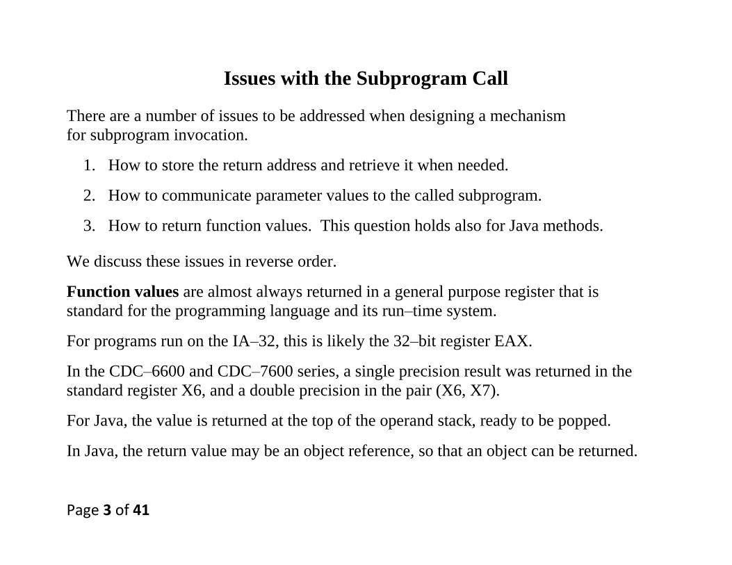
Issues with the Subprogram Call
There are a number of issues to be addressed when designing a mechanism
for subprogram invocation.
1. How to store the return address and retrieve it when needed.
2. How to communicate parameter values to the called subprogram.
3. How to return function values. This question holds also for Java methods.
We discuss these issues in reverse order.
Function values are almost always returned in a general purpose register that is
standard for the programming language and its run–time system.
For programs run on the IA–32, this is likely the 32–bit register EAX.
In the CDC–6600 and CDC–7600 series, a single precision result was returned in the
standard register X6, and a double precision in the pair (X6, X7).
For Java, the value is returned at the top of the operand stack, ready to be popped.
In Java, the return value may be an object reference, so that an object can be returned.

Page 4 of 41
Communicating Parameter Values
The idea of a subprogram is based on the passing and returning of parameter values.
There are many methods for passing parameter values.
The two common methods are call by reference and call by value.
In the call by value protocol, it is the value of the argument that is passed. Any
changes made to that argument are local to the subprogram and not returned.
Consider the following code fragments.
Main Sub1
X = 2 SUB1 (ByValue X)
CALL SUB1(X) X = X + 1
Y = X PRINT X
PRINT Y RETURN
When the subprogram prints the value, it prints a 3.
When the main program prints the value, it prints a 2.
Note that the change in the value of X is not communicated back to the calling program.
Page 5 of 41
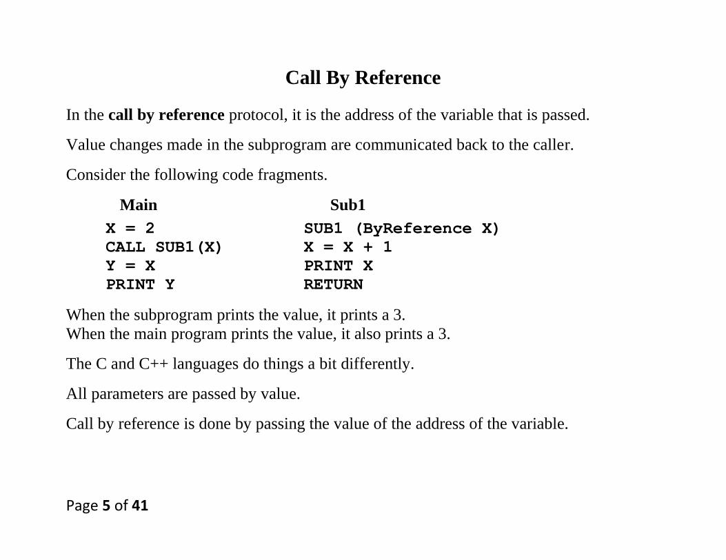
Call By Reference
In the call by reference protocol, it is the address of the variable that is passed.
Value changes made in the subprogram are communicated back to the caller.
Consider the following code fragments.
Main Sub1
X = 2 SUB1 (ByReference X)
CALL SUB1(X) X = X + 1
Y = X PRINT X
PRINT Y RETURN
When the subprogram prints the value, it prints a 3.
When the main program prints the value, it also prints a 3.
The C and C++ languages do things a bit differently.
All parameters are passed by value.
Call by reference is done by passing the value of the address of the variable.
Page 6 of 41
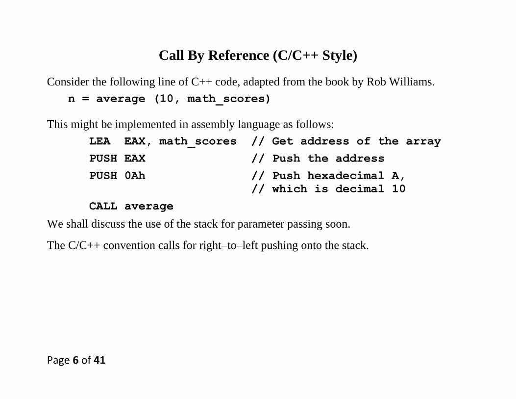
Call By Reference (C/C++ Style)
Consider the following line of C++ code, adapted from the book by Rob Williams.
n = average (10, math_scores)
This might be implemented in assembly language as follows:
LEA EAX, math_scores // Get address of the array
PUSH EAX // Push the address
PUSH 0Ah // Push hexadecimal A,
// which is decimal 10
CALL average
We shall discuss the use of the stack for parameter passing soon.
The C/C++ convention calls for right–to–left pushing onto the stack.
Page 7 of 41
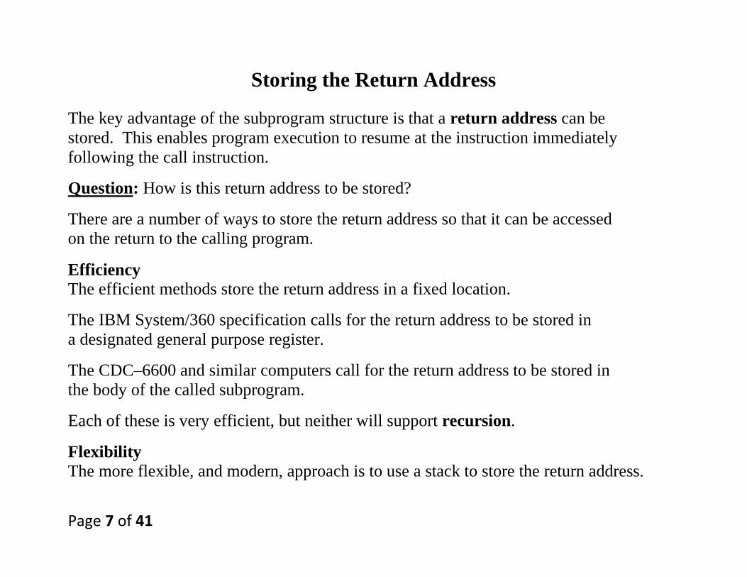
Storing the Return Address
The key advantage of the subprogram structure is that a return address can be
stored. This enables program execution to resume at the instruction immediately
following the call instruction.
Question: How is this return address to be stored?
There are a number of ways to store the return address so that it can be accessed
on the return to the calling program.
Efficiency
The efficient methods store the return address in a fixed location.
The IBM System/360 specification calls for the return address to be stored in
a designated general purpose register.
The CDC–6600 and similar computers call for the return address to be stored in
the body of the called subprogram.
Each of these is very efficient, but neither will support recursion.
Flexibility
The more flexible, and modern, approach is to use a stack to store the return address.

Page 8 of 41
The Original Way to Store the Return Address
The simplest way is to store the return address in the subroutine.
This is the method used by many older computers, such as the CDC–6600.
A subprogram at address Z would be invoked by a call such as JSR Z.
The return address would be stored at address Z and execution begin at (Z + 1).
Note that the last executable instruction is an indirect jump.
1. Go to address Z and get the contents of that address.
2. Use the contents of that address as the target address for the jump.
Page 9 of 41
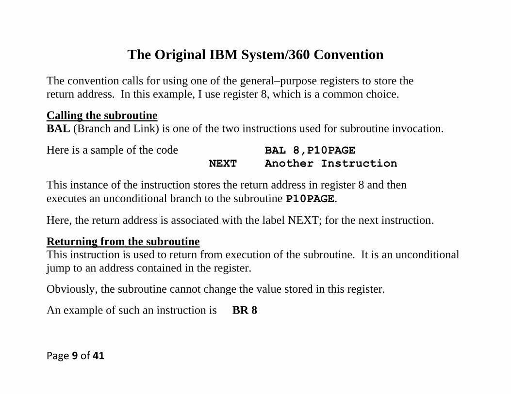
The Original IBM System/360 Convention
The convention calls for using one of the general–purpose registers to store the
return address. In this example, I use register 8, which is a common choice.
Calling the subroutine
BAL (Branch and Link) is one of the two instructions used for subroutine invocation.
Here is a sample of the code BAL 8,P10PAGE
NEXT Another Instruction
This instance of the instruction stores the return address in register 8 and then
executes an unconditional branch to the subroutine P10PAGE.
Here, the return address is associated with the label NEXT; for the next instruction.
Returning from the subroutine
This instruction is used to return from execution of the subroutine. It is an unconditional
jump to an address contained in the register.
Obviously, the subroutine cannot change the value stored in this register.
An example of such an instruction is BR 8

Page 10 of 41
Sample CDC–6600 Call (Not Recursive)
Suppose the following instructions
100 JSR 200
101 Next Instruction
200 Holder for Return Address
201 First Instruction
Last BR *200
After the subroutine call, we would have
100 JSR 200
101 Next Instruction
200 101
201 First Instruction
Last BR *200
The BR*200 would cause a branch to address 101, thus causing a proper return.
Page 11 of 41
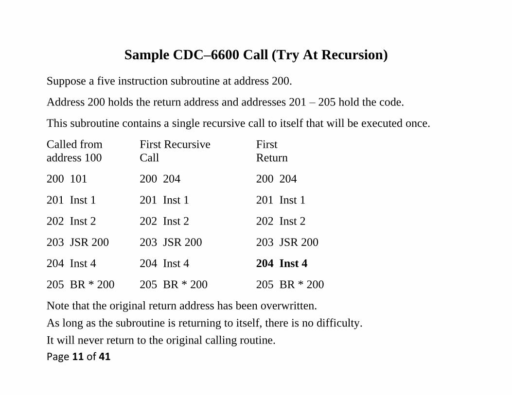
Sample CDC–6600 Call (Try At Recursion)
Suppose a five instruction subroutine at address 200.
Address 200 holds the return address and addresses 201 – 205 hold the code.
This subroutine contains a single recursive call to itself that will be executed once.
Called from First Recursive First
address 100 Call Return
200 101 200 204 200 204
201 Inst 1 201 Inst 1 201 Inst 1
202 Inst 2 202 Inst 2 202 Inst 2
203 JSR 200 203 JSR 200 203 JSR 200
204 Inst 4 204 Inst 4 204 Inst 4
205 BR * 200 205 BR * 200 205 BR * 200
Note that the original return address has been overwritten.
As long as the subroutine is returning to itself, there is no difficulty.
It will never return to the original calling routine.

Page 12 of 41
Writing Recursive Subroutines
We note immediately that neither of the above methods will support recursion,
because each will lose track of return addresses.
The standard way to track return addresses is to use a stack.
Here is how the use of a stack corrects the problem above.
Main calls the subroutine SP 101
The subroutine calls itself SP 204 101
First return Pop the return address from the stack
RA = 204
SP 101
The subroutine returns to itself.
Second return Pop the return address from the stack
RA = 101
The subroutine returns to the main program.

Page 13 of 41
Tail Recursion
A subprogram is called “tail recursive” if the recursive call is the
last executable statement in the subprogram.
Modern compilers can convert tail recursive subprograms into non–recursive
equivalents that use iteration. These are far more efficient.
The best example is the factorial function.
Integer Factorial (Integer N)
If (N < 2) Then Return 1 ;
Else Return N*Factorial(N – 1);
Here is the equivalent code that would be actually compiled to machine language.
Integer Factorial (Integer N)
Integer F = 1 ;
For (Integer K = N, K > 1, K--)
Do F = F * K ;
Return F ;
Page 14 of 41
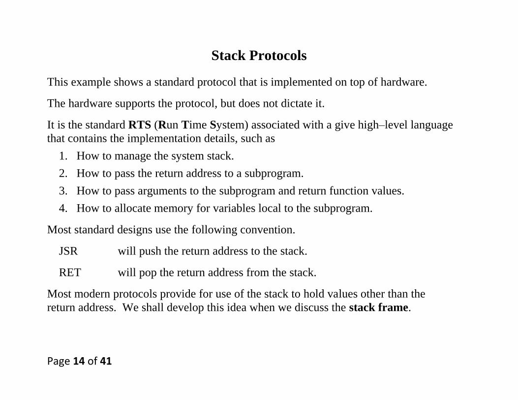
Stack Protocols
This example shows a standard protocol that is implemented on top of hardware.
The hardware supports the protocol, but does not dictate it.
It is the standard RTS (Run Time System) associated with a give high–level language
that contains the implementation details, such as
1. How to manage the system stack.
2. How to pass the return address to a subprogram.
3. How to pass arguments to the subprogram and return function values.
4. How to allocate memory for variables local to the subprogram.
Most standard designs use the following convention.
JSR will push the return address to the stack.
RET will pop the return address from the stack.
Most modern protocols provide for use of the stack to hold values other than the
return address. We shall develop this idea when we discuss the stack frame.

Page 15 of 41
Management of Dynamic Memory
In order to understand the use of a stack in managing subprograms, we must
first see the stack as one of two important dynamic data structures.
The stack is a LIFO (Last In – First Out) data structure that is quite useful in allocation
of memory for subprogram calls: return address, local variables, arguments, etc.
The heap is a semi–structured data collection used to allocate memory for dynamic
variables that are created by operators such as the Java new() or C++ malloc().
Typically, a RTS (Run Time System) will allocate a block of memory to be shared
between the stack and the heap, without setting direct limits on either.
The standard arrangement is to have the stack start at high
addresses and grow towards low addresses.
The heap starts at low addresses and grows toward the high.
In the MIPS memory allocation
the stack pointer is initialized to 0x7FFF FFFC, and
the heap pointer is initialized to 0x1000 8004.
The two grow towards each other.

Page 16 of 41
The IA–32 Stack
The tendency of the stack to grow down gives rise to a situation that
is not intuitive. The stack top is the lowest address on the stack.
The IA–32 architecture calls for stacking only 32–bit values.
The following diagram might reflect the memory map associated with
the stack on an IA–32 machine.
In this example the values were pushed in this order: 6 (first), 5, 4, 3, and then 2.
The stack top has the lowest address.
Page 17 of 41
Implementation of the Stack Operations
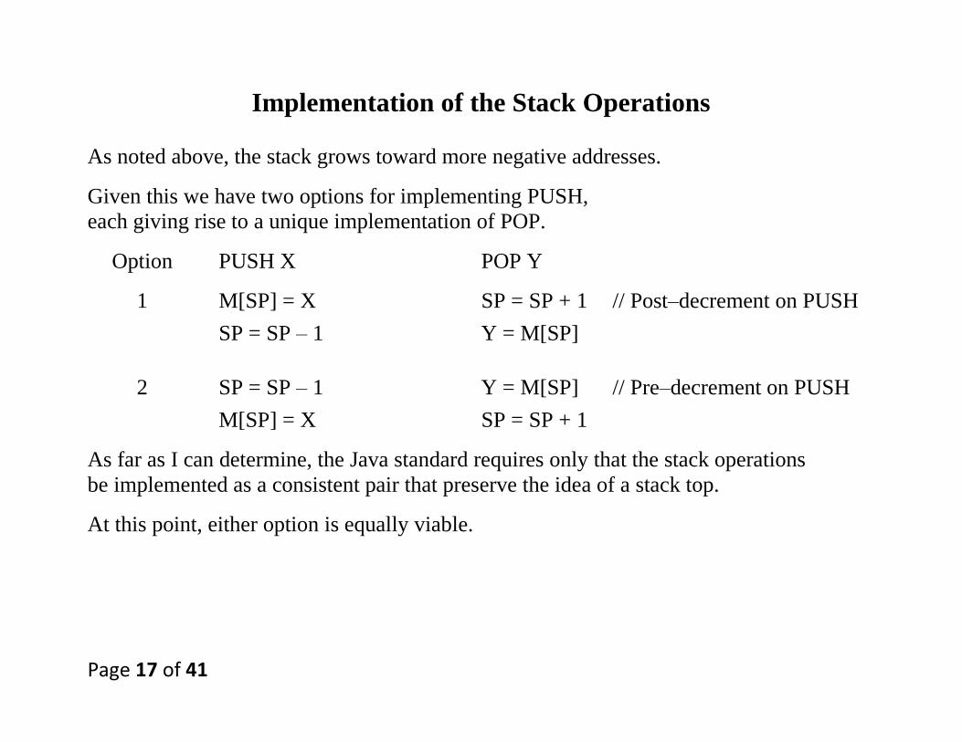
As noted above, the stack grows toward more negative addresses.
Given this we have two options for implementing PUSH,
each giving rise to a unique implementation of POP.
Option PUSH X POP Y
1 M[SP] = X SP = SP + 1 // Post–decrement on PUSH
SP = SP – 1 Y = M[SP]
2 SP = SP – 1 Y = M[SP] // Pre–decrement on PUSH
M[SP] = X SP = SP + 1
As far as I can determine, the Java standard requires only that the stack operations
be implemented as a consistent pair that preserve the idea of a stack top.
At this point, either option is equally viable.

Page 18 of 41
The IA–32 Stack Protocol
More properly, this is the MS–DOS and MS–Windows protocol.
This protocol is uniform for the run time systems that support compilers for
high–level languages run under MS–DOS and MS–Windows.
This protocol uses two registers found in the IA–32.
ESP The 32–bit stack pointer, used to indicate the top of the stack.
EBP The 32–bit base pointer, used to manipulate the stack frame.
The stack protocol is pre–decrement, post–increment.
PUSH ESP = ESP - 4 // Decrement the stack pointer
MEM[ESP] = VALUE // Place the item on the stack
POP VALUE = MEM[ESP] // Get the value
ESP = ESP + 4 // Increment the stack pointer
The RTS calls for only 32–bit values to be stored on the stack.
Page 19 of 41
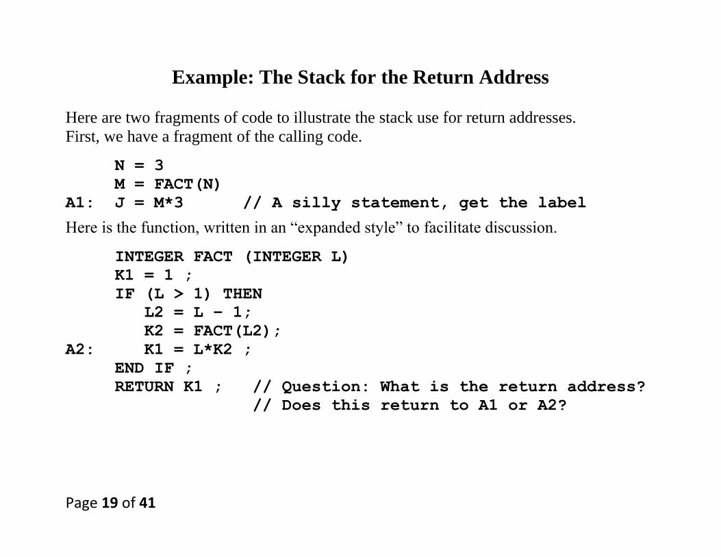
Example: The Stack for the Return Address
Here are two fragments of code to illustrate the stack use for return addresses.
First, we have a fragment of the calling code.
N = 3
M = FACT(N)
A1: J = M*3 // A silly statement, get the label
Here is the function, written in an “expanded style” to facilitate discussion.
INTEGER FACT (INTEGER L)
K1 = 1 ;
IF (L > 1) THEN
L2 = L – 1;
K2 = FACT(L2);
A2: K1 = L*K2 ;
END IF ;
RETURN K1 ; // Question: What is the return address?
// Does this return to A1 or A2?

Page 20 of 41
Follow the Stack (Part 1)
M = FACT(N)
The return address placed on the stack is that
of a statement in the calling program.
L = 3, L2 = 2. K2 = FACT(L2)
Here, this is called from within the FACT function.
It is the return address within the function that is
stored on the stack.
Page 21 of 41
Follow the Stack (Part 2)
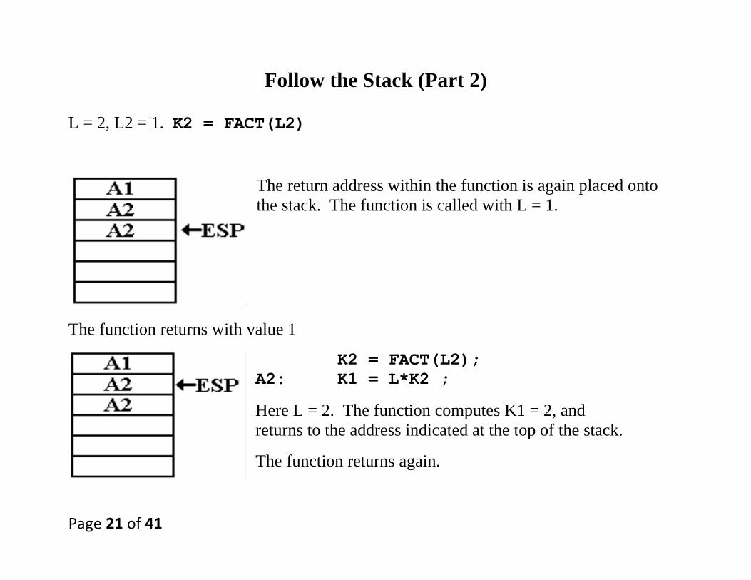
L = 2, L2 = 1. K2 = FACT(L2)
The return address within the function is again placed onto
the stack. The function is called with L = 1.
The function returns with value 1
K2 = FACT(L2);
A2: K1 = L*K2 ;
Here L = 2. The function computes K1 = 2, and
returns to the address indicated at the top of the stack.
The function returns again.
Page 22 of 41
Follow the Stack (Part 3)
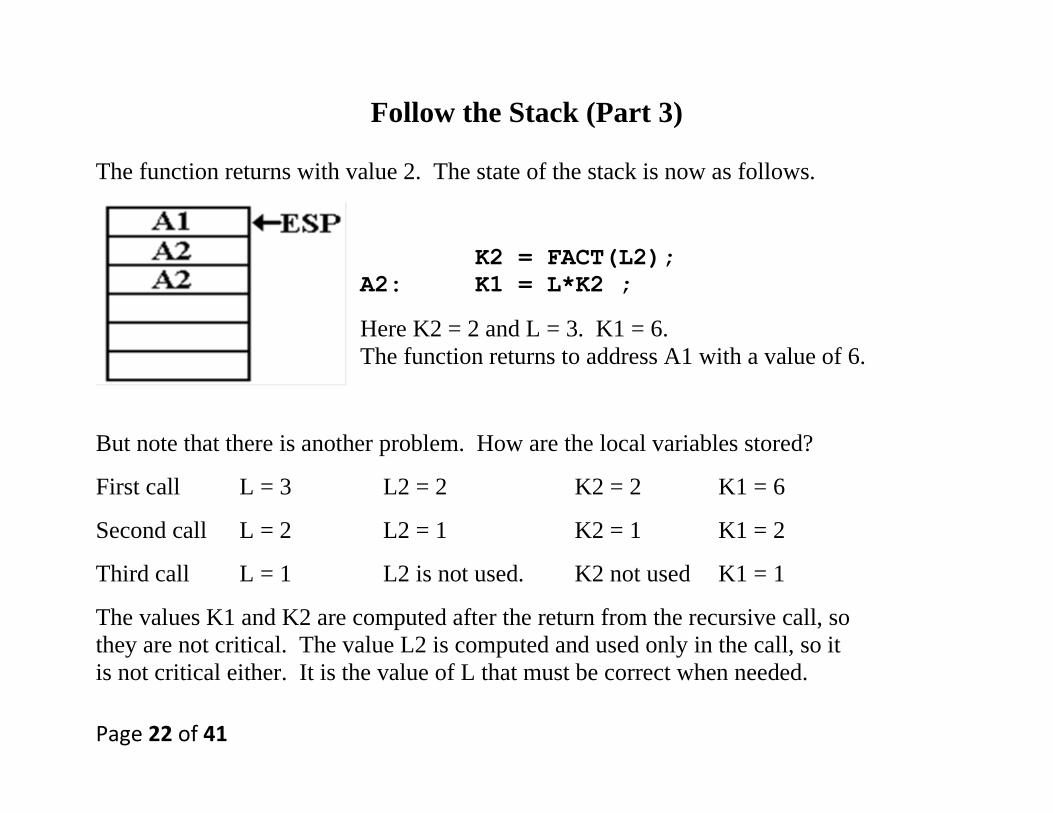
The function returns with value 2. The state of the stack is now as follows.
K2 = FACT(L2);
A2: K1 = L*K2 ;
Here K2 = 2 and L = 3. K1 = 6.
The function returns to address A1 with a value of 6.
But note that there is another problem. How are the local variables stored?
First call L = 3 L2 = 2 K2 = 2 K1 = 6
Second call L = 2 L2 = 1 K2 = 1 K1 = 2
Third call L = 1 L2 is not used. K2 not used K1 = 1
The values K1 and K2 are computed after the return from the recursive call, so
they are not critical. The value L2 is computed and used only in the call, so it
is not critical either. It is the value of L that must be correct when needed.

Page 23 of 41
Use the Stack for Arguments
We have described the use of the stack to handle return addresses.
We now extend this discussion to the use of the stack for passing arguments.
The two common ways to pass an argument are call by value (passing the value of the
argument) and call by reference (passing the address of the argument).
At this level, we just consider proper stack handling of 32–bit parameters, which might
be values or addresses. The basic mechanism is independent of the parameter’s use.
Here is the basic script at this point.
1. Push the parameters onto the stack.
For call by value, push the value of the argument.
For call by reference, push the address of the argument.
2. Push the return address onto the stack.
3. The called routine accesses the stack to get at the parameters.
4. The called routine pops the return address from the stack and returns.
Page 24 of 41
Two Calling Conventions
Consider the high–level language statement.
PROCA (L, M, N)
In what order are the arguments pushed onto the stack?
In the Pascal convention, the arguments are pushed left–to–right.
The sequence for a Pascal–like language would be PUSH L
PUSH M
PUSH N
CALL PROCA
In the C/C++ convention, the arguments are pushed right–to–left.
The sequence for a C–like language would be PUSH N
PUSH M
PUSH L
CALL PROCA
The CALL instruction pushes the return address onto the stack.

Page 25 of 41
MS–Windows Uses the Pascal Calling Convention
Though mostly written in C and C++, MS–Windows uses the Pascal convention.
Here is a sample header description for a MS–Windows API function.
BOOL WINAPI CopyFileEx(
__in LPCTSTR lpExistingFileName,
__in LPCTSTR lpNewFileName,
__in_opt LPPROGRESS_ROUTINE lpProgressRoutine,
__in_opt LPVOID lpData,
__in_opt LPBOOL pbCancel,
__in DWORD dwCopyFlags
);
BOOL The function returns a Boolean value: TRUE or FALSE.
WINAPI This is a descriptor for the calling convention used. This is
the new name for the older __stdcall name, which itself
replaces the name __pascal, for the Pascal convention.
Page 26 of 41
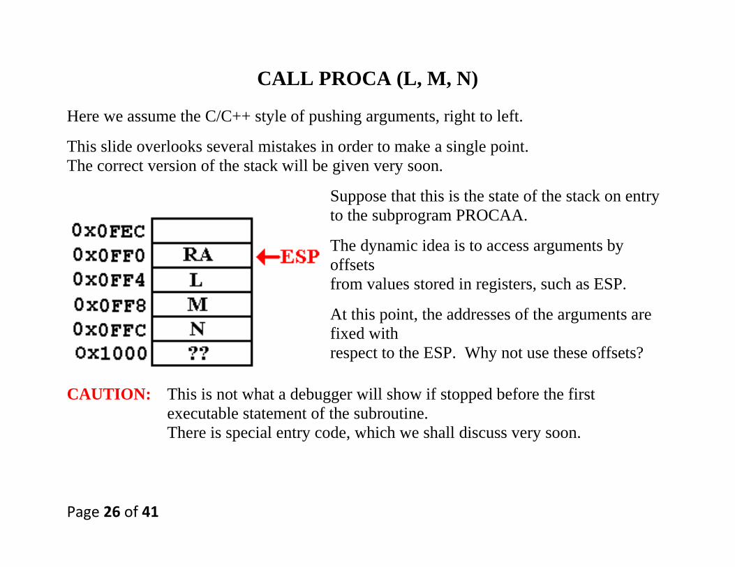
CALL PROCA (L, M, N)
Here we assume the C/C++ style of pushing arguments, right to left.
This slide overlooks several mistakes in order to make a single point.
The correct version of the stack will be given very soon.
Suppose that this is the state of the stack on entry
to the subprogram PROCAA.
The dynamic idea is to access arguments by
offsets
from values stored in registers, such as ESP.
At this point, the addresses of the arguments are
fixed with
respect to the ESP. Why not use these offsets?
CAUTION: This is not what a debugger will show if stopped before the first
executable statement of the subroutine.
There is special entry code, which we shall discuss very soon.

Page 27 of 41
The Stack Frame
The stack frame, also known as the “call stack”, is the basic mechanism for storing
variables that are local to a called subprogram.
In the terminology of C and C++, these are called “automatic variables”.
These variables have meaning only within the called subprogram itself.
Suppose that the subprogram PROCA used four 32–bit variables I, J, K and K1.
The entry code for PROCA would allocate 4 stack
slots to hold these variables.
This entry code is executed immediately upon
entry to the subprogram, before the first
executable line of the subprogram.
Again, this is not quite the complete picture.
We shall evolve that soon.
Note for the moment that this might complicate
the use of ESP as a base register for addressing
the arguments that were passed.
Page 28 of 41
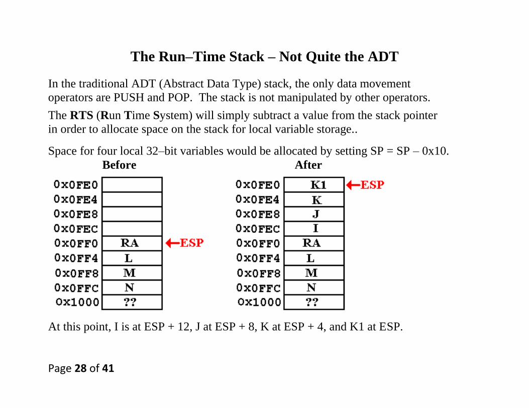
The Run–Time Stack – Not Quite the ADT
In the traditional ADT (Abstract Data Type) stack, the only data movement
operators are PUSH and POP. The stack is not manipulated by other operators.
The RTS (Run Time System) will simply subtract a value from the stack pointer
in order to allocate space on the stack for local variable storage..
Space for four local 32–bit variables would be allocated by setting SP = SP – 0x10.
Before After
At this point, I is at ESP + 12, J at ESP + 8, K at ESP + 4, and K1 at ESP.
Page 29 of 41
The Base Pointer EBP
Again, we note that the picture at this point is not quite complete.
We need one more feature to complete the design of a stack frame.
We now discuss the mechanism chosen to allow for register & offset access to items
in the stack without directly using the stack pointer, ESP.
The mechanism is called the frame pointer or the base pointer.
In the IA–32, this is the function of the 32–bit EBP register.
The base pointer will be used to reference:
1. The parameters passed to the subprogram , and
2. The variables local to the subprogram.
This frees the design to allow the stack pointer, ESP, to vary in accordance with
the needs of stack management.
Page 30 of 41
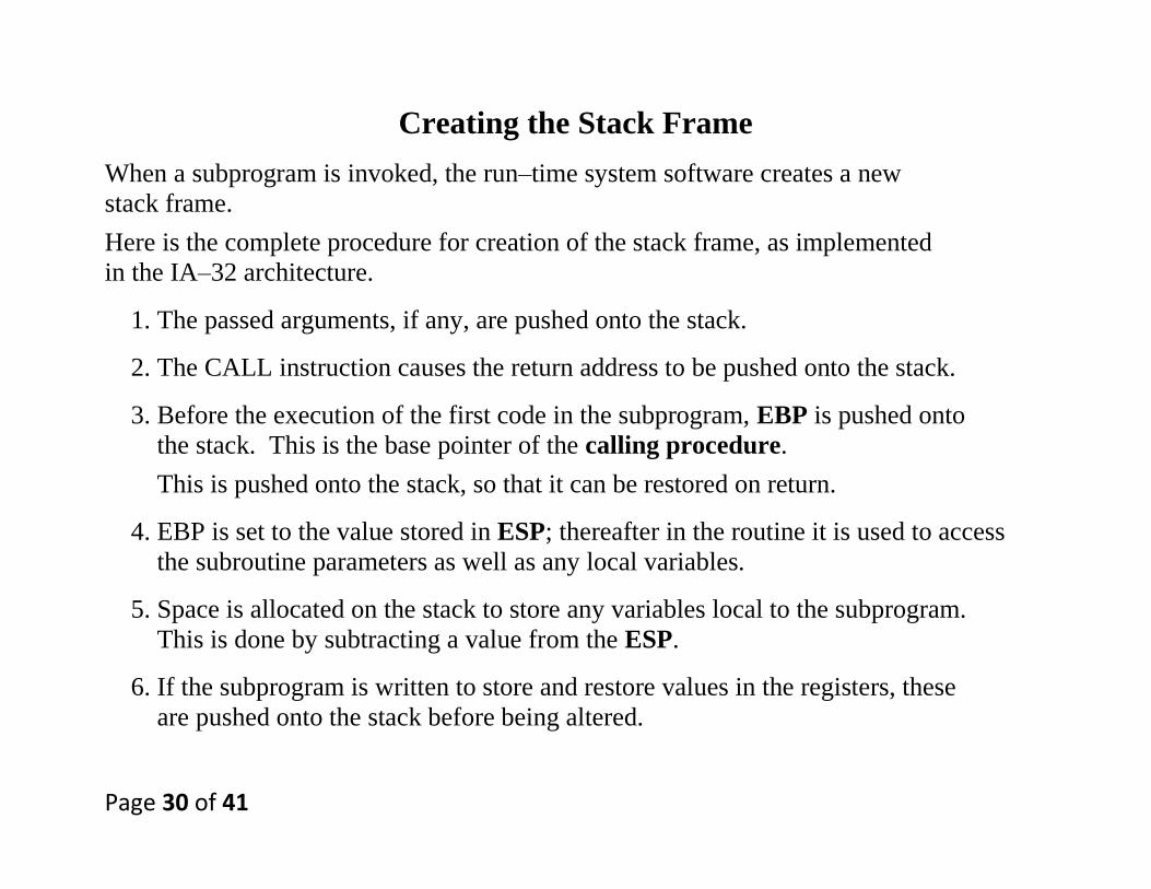
Creating the Stack Frame
When a subprogram is invoked, the run–time system software creates a new
stack frame.
Here is the complete procedure for creation of the stack frame, as implemented
in the IA–32 architecture.
1. The passed arguments, if any, are pushed onto the stack.
2. The CALL instruction causes the return address to be pushed onto the stack.
3. Before the execution of the first code in the subprogram, EBP is pushed onto
the stack. This is the base pointer of the calling procedure.
This is pushed onto the stack, so that it can be restored on return.
4. EBP is set to the value stored in ESP; thereafter in the routine it is used to access
the subroutine parameters as well as any local variables.
5. Space is allocated on the stack to store any variables local to the subprogram.
This is done by subtracting a value from the ESP.
6. If the subprogram is written to store and restore values in the registers, these
are pushed onto the stack before being altered.

Page 31 of 41
Example Call
Here is a simple implementation of the function, written in Pseudo–Java.
INT PROCA (INT I, INT J, INT K)
{
INT K1 ;
K1 = I + J + K ; // K1 is a 32-bit value.
RETURN K1 ;
}
Assuming that the variables L, M, and N have been properly initialized,
this might be invoked as follows:
K2 = PROCA (L, M, N) ;

Page 32 of 41
A Possible Assembly Language Implementation of the Call
In this, we assume that the register EAX is use to return the function value.
Here is a possible assembly language implementation.
; K2 = PROCA (L, M, N)
0x3FFC PUSH EAX // Save the value of EAX
0x4000 PUSH N
0x4004 PUSH M
0x4008 PUSH L
0x400C CALL PROCA
0x4010 ADD ESP, 12 // Clear parameters from stack
0x4014 MOV K2, EAX
0x4018 POP EAX // Get the old EAX back.
Some implementations might not save the value of the register used to
return the function value.
This code choice just shows what is possible.

Page 33 of 41
Step–By–Step Illustration of the Stack
In this illustration, we assume that the arguments have the following values.
L = 16 (0x10)
M = 32 (0x20)
N = 50 (0x32)
We assume some addresses for the stack.
In particular, that ESP = 0x1000 before the call is executed.
Assume that, just before the call, the registers EAX and EBP
have the following values.
EAX contains 0x2222
EBP contains 0x100C.
Page 34 of 41
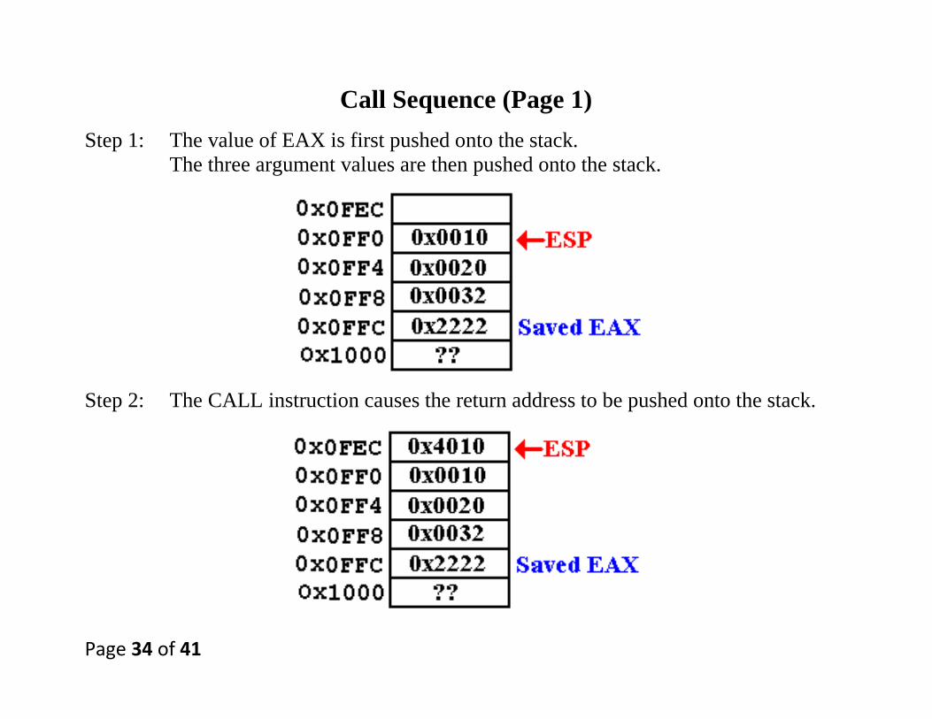
Call Sequence (Page 1)
Step 1: The value of EAX is first pushed onto the stack.
The three argument values are then pushed onto the stack.
Step 2: The CALL instruction causes the return address to be pushed onto the stack.
Page 35 of 41
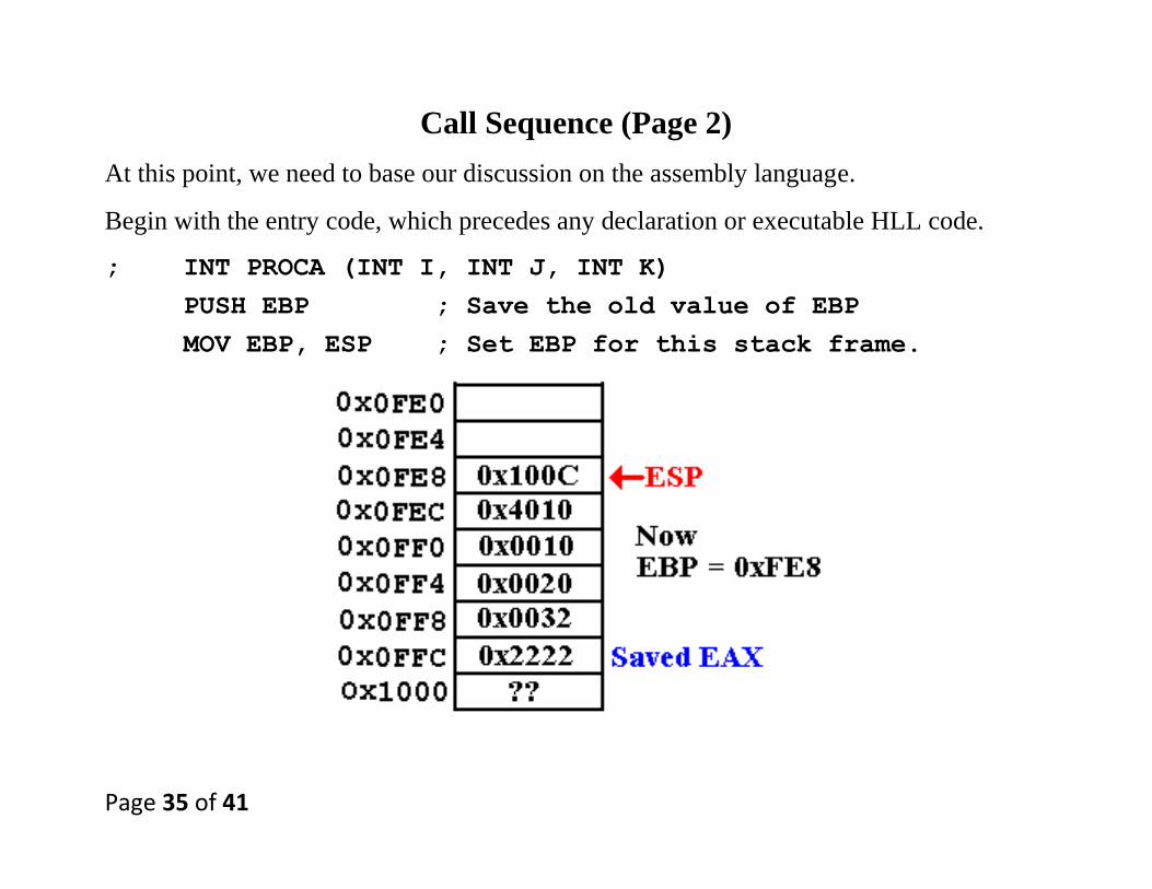
Call Sequence (Page 2)
At this point, we need to base our discussion on the assembly language.
Begin with the entry code, which precedes any declaration or executable HLL code.
; INT PROCA (INT I, INT J, INT K)
PUSH EBP ; Save the old value of EBP
MOV EBP, ESP ; Set EBP for this stack frame.
Page 36 of 41
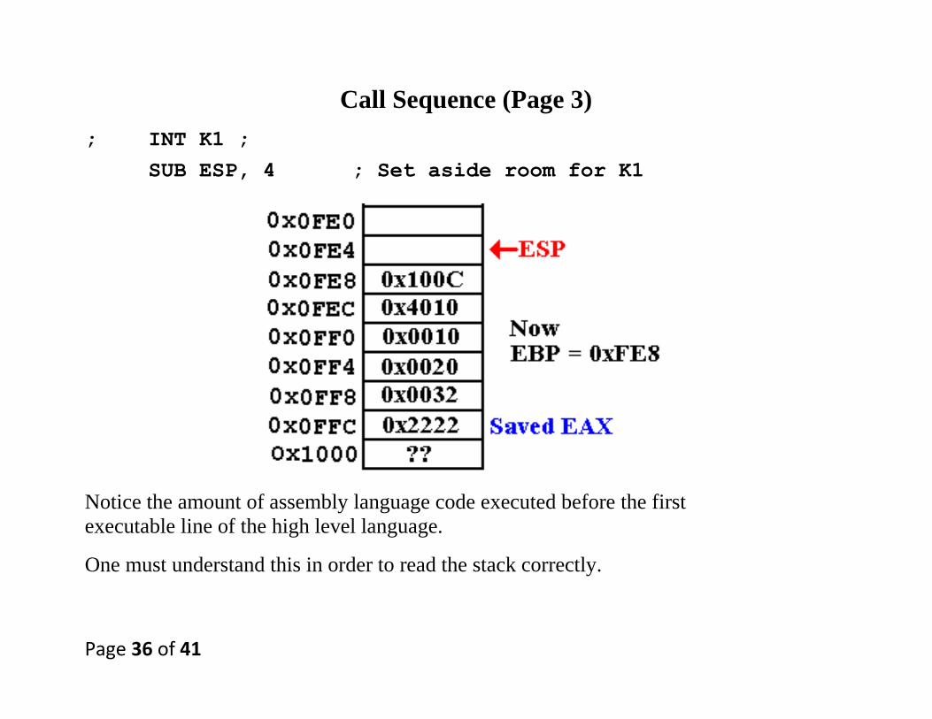
Call Sequence (Page 3)
; INT K1 ;
SUB ESP, 4 ; Set aside room for K1
Notice the amount of assembly language code executed before the first
executable line of the high level language.
One must understand this in order to read the stack correctly.

Page 37 of 41
Call Sequence (Page 4)
; K1 = I + J + K ;
MOV EAX, [EBP + 8] ; Get value
ADD EAX, [EBP + 12]
ADD EAX, [EBP + 16]
MOV [EBP – 4], EAX

Page 38 of 41
Call Sequence (Page 4)
The first part of the return sequence sets the value of EAX to the return value.
Then the process of clearing the stack frame begins, by resetting ESP almost
to the value needed for the return.
; RETURN K1 ;
MOV EAX, [EBP – 4]
MOV ESP, EBP

Page 39 of 41
Call Sequence (Page 5)
The next part of the return sequence sets the value of EBP to its saved value.
POP EBP

Page 40 of 41
Call Sequence (Page 6)
The final part of the return sequence pops the return address and executes the return.
RET

Page 41 of 41
The Return Sequence in the Calling Code
0x4010 ADD ESP, 12 // Clear parameters from stack
0x4014 MOV K2, EAX
0x4018 POP EAX // Get the old EAX back.


![•Stack Instructions: PUSH, POP •Subroutines (a.k.a ...CMSC 313 Lecture 8 [draft] • •Stack Instructions: PUSH, POP •Subroutines (a.k.a. Functions) in Assembly •Interrupts](https://static.fdocuments.in/doc/165x107/5f0930e27e708231d425a880/astack-instructions-push-pop-asubroutines-aka-cmsc-313-lecture-8-draft.jpg)