Subpart 56.50—Design Require- ments Pertaining to … · 2018-03-17 · (For plastic pipe...
26
192 46 CFR Ch. I (10–1–10 Edition) § 56.50–1 Subpart 56.50—Design Require- ments Pertaining to Specific Systems § 56.50–1 General (replaces 122). The requirements in this subpart for piping systems apply instead of those in section 122 of ASME B31.1 (incor- porated by reference; see 46 CFR 56.01– 2). Installation requirements applicable to all systems: (a) Where pipes and scuppers are car- ried through watertight or oiltight bulkheads, decks or tank tops, or are carried through fire control bulkheads and decks, the integrity of the struc- ture shall be maintained. Lead or other heat sensitive materials shall not be used in piping systems which make such bulkhead or deck penetrations where the deterioration of such sys- tems in the event of fire would impair the integrity of the bulkheads or decks. (For plastic pipe installations, see § 56.60–25(a).) Where plate insert pads are used, bolted connections shall have threads tapped into the plate to a depth of not less than the diameter of the bolt. If welded, the pipe or flange shall be welded to both sides of the plating. Openings in structure through which pipes pass shall be reinforced where necessary. Flanges shall not be bolted to bulkheads so that the plate forms a part of the joint. Metallic ma- terials having a melting point of 1,700 °F. or less are considered heat sensitive and if used must be suitably insulated. (b)(1) Pipes piercing the collision bulkhead shall be fitted with screwdown valves operable from above the bulkhead deck and the valve shall be fitted inside the forepeak tank adja- cent to the collision bulkhead. The pipe penetrating the collision bulkhead shall be welded to the bulkhead on both sides. On new installations or re- placement in vessels of 150 gross tons and over, the valve body shall be of steel or ductile cast iron. (2) Passenger vessels shall not have the collision bulkhead pierced below the margin line by more than one pipe conveying liquids in the forepeak tank except that if the forepeak tank is di- vided to hold two different kinds of liq- uids, the collision bulkhead may be pierced below the margin line by two pipes, provided there is no practical al- ternative to the fitting of the second pipe and further provided the safety of the vessel is maintained. (c) Valves and cocks not forming part of a piping system are not permitted in watertight subdivision bulkheads, how- ever, sluice valves or gates in oiltight bulkheads of tankships may be used if approved by the Marine Safety Center. (d) Piping shall not be run over or in the vicinity of switchboards or other electrical equipment if avoidable. When such leads are necessary, welded joints only shall be used and provision shall be made to prevent leakage from damaging the equipment. (e) Stuffing boxes shall not be used on deep tank bulkheads, double bot- toms or in any position where they cannot be easily examined. This re- quirement does not apply to ore car- riers operating on the Great Lakes or cargo lines of oil tankers. (f) Piping systems shall be installed so that under no condition will the op- eration of safety or relief valves be im- paired. (g)(1) Power actuated valves in sys- tems other than as specified in § 56.50– 60 of this part may be used if approved for the system by the Marine Safety Center. All power actuated valves re- quired in an emergency to operate the vessel’s machinery, to maintain its sta- bility, and to operate the bilge and firemain systems must have a manual means of operation. (2)(i) Remote valve controls that are not readily identifiable as to service must be fitted with nameplates. (ii) Remote valve controls must be accessible under service conditions. (iii) Remote valve controls, except reach rods, must be fitted with indica- tors that show whether the valves they control are open or closed. Valve posi- tion indicating systems must be inde- pendent of valve control systems. (iv) Valve reach rods must be ade- quately protected. (v) Solid reach rods must be used in tanks containing liquids, except that tank barges having plug cocks inside cargo tanks may have reach rods of extra-heavy pipe with the annular space between the lubricant tube and the pipe wall sealed with a nonsoluble to prevent penetration of the cargo. VerDate Mar<15>2010 09:56 Dec 08, 2010 Jkt 220192 PO 00000 Frm 00202 Fmt 8010 Sfmt 8010 Y:\SGML\220192.XXX 220192 jdjones on DSK8KYBLC1PROD with CFR
Transcript of Subpart 56.50—Design Require- ments Pertaining to … · 2018-03-17 · (For plastic pipe...
192
46 CFR Ch. I (10–1–10 Edition) § 56.50–1
Subpart 56.50—Design Require-ments Pertaining to Specific Systems
§ 56.50–1 General (replaces 122). The requirements in this subpart for
piping systems apply instead of those in section 122 of ASME B31.1 (incor-porated by reference; see 46 CFR 56.01– 2). Installation requirements applicable to all systems:
(a) Where pipes and scuppers are car-ried through watertight or oiltight bulkheads, decks or tank tops, or are carried through fire control bulkheads and decks, the integrity of the struc-ture shall be maintained. Lead or other heat sensitive materials shall not be used in piping systems which make such bulkhead or deck penetrations where the deterioration of such sys-tems in the event of fire would impair the integrity of the bulkheads or decks. (For plastic pipe installations, see § 56.60–25(a).) Where plate insert pads are used, bolted connections shall have threads tapped into the plate to a depth of not less than the diameter of the bolt. If welded, the pipe or flange shall be welded to both sides of the plating. Openings in structure through which pipes pass shall be reinforced where necessary. Flanges shall not be bolted to bulkheads so that the plate forms a part of the joint. Metallic ma-terials having a melting point of 1,700 °F. or less are considered heat sensitive and if used must be suitably insulated.
(b)(1) Pipes piercing the collision bulkhead shall be fitted with screwdown valves operable from above the bulkhead deck and the valve shall be fitted inside the forepeak tank adja-cent to the collision bulkhead. The pipe penetrating the collision bulkhead shall be welded to the bulkhead on both sides. On new installations or re-placement in vessels of 150 gross tons and over, the valve body shall be of steel or ductile cast iron.
(2) Passenger vessels shall not have the collision bulkhead pierced below the margin line by more than one pipe conveying liquids in the forepeak tank except that if the forepeak tank is di-vided to hold two different kinds of liq-uids, the collision bulkhead may be pierced below the margin line by two pipes, provided there is no practical al-
ternative to the fitting of the second pipe and further provided the safety of the vessel is maintained.
(c) Valves and cocks not forming part of a piping system are not permitted in watertight subdivision bulkheads, how-ever, sluice valves or gates in oiltight bulkheads of tankships may be used if approved by the Marine Safety Center.
(d) Piping shall not be run over or in the vicinity of switchboards or other electrical equipment if avoidable. When such leads are necessary, welded joints only shall be used and provision shall be made to prevent leakage from damaging the equipment.
(e) Stuffing boxes shall not be used on deep tank bulkheads, double bot-toms or in any position where they cannot be easily examined. This re-quirement does not apply to ore car-riers operating on the Great Lakes or cargo lines of oil tankers.
(f) Piping systems shall be installed so that under no condition will the op-eration of safety or relief valves be im-paired.
(g)(1) Power actuated valves in sys-tems other than as specified in § 56.50– 60 of this part may be used if approved for the system by the Marine Safety Center. All power actuated valves re-quired in an emergency to operate the vessel’s machinery, to maintain its sta-bility, and to operate the bilge and firemain systems must have a manual means of operation.
(2)(i) Remote valve controls that are not readily identifiable as to service must be fitted with nameplates.
(ii) Remote valve controls must be accessible under service conditions.
(iii) Remote valve controls, except reach rods, must be fitted with indica-tors that show whether the valves they control are open or closed. Valve posi-tion indicating systems must be inde-pendent of valve control systems.
(iv) Valve reach rods must be ade-quately protected.
(v) Solid reach rods must be used in tanks containing liquids, except that tank barges having plug cocks inside cargo tanks may have reach rods of extra-heavy pipe with the annular space between the lubricant tube and the pipe wall sealed with a nonsoluble to prevent penetration of the cargo.
VerDate Mar<15>2010 09:56 Dec 08, 2010 Jkt 220192 PO 00000 Frm 00202 Fmt 8010 Sfmt 8010 Y:\SGML\220192.XXX 220192jdjo
nes
on D
SK
8KY
BLC
1PR
OD
with
CF
R

193
Coast Guard, Dept. of Homeland Security § 56.50–15
(3) Air operated remote control valves must be provided with self-indi-cating lines at the control boards which indicate the desired valve posi-tions, i.e., open or closed.
(h) Suitable drains shall be provided at low points of piping systems.
(i) Valves and cocks shall be located so as to be easily accessible and valves or cocks attached to the shell of the vessel or to sea chests located below the floorplating shall be operable from above the floorplates.
(j) When welded fabrication is em-ployed, a sufficient number of detach-able joints shall be provided to facili-tate overhauling and maintenance of machinery and appurtenances. The joints shall be located so that adequate space is provided for welding, and the location of the welds shall be indicated on the plans.
(k) Piping, including valves, pipe fit-tings and flanges, conveying vapors, gases or liquids whose temperature ex-ceeds 150 °F., shall be suitably insu-lated where necessary to preclude in-jury to personnel.
(l) Where pipes are run through dry cargo spaces they must be protected from mechanical injury by a suitable enclosure or other means.
[CGFR 68–82, 33 FR 18843, Dec. 18, 1968, as amended by CGFR 69–127, 35 FR 9978, June 17, 1970; CGD 77–140, 54 FR 40607, Oct. 2, 1989; USCG–2003–16630, 73 FR 65178, Oct. 31, 2008]
§ 56.50–10 Special gauge requirements.
(a) Where pressure-reducing valves are employed, a pressure gauge must be provided on the low-pressure side of the reducing station.
(b) Fuel oil service, fire, cargo and fuel oil transfer and boiler feed pumps must be provided with a pressure gage on the discharge side of the pump. Ad-ditional information pertaining to fire pumps is in § 34.10–5 of subchapter D (Tank Vessels), § 76.10–5 of subchapter H (Passenger Vessels), § 95.10–5 of sub-chapter I (Cargo and Miscellaneous Vessels), and § 108.417 of subchapter IA (Mobile Offshore Drilling Units) of this chapter.
[CGFR 68–82, 33 FR 18843, Dec. 18, 1968, as amended by CGFR 69–127, 35 FR 9978, June 17, 1970; CGD 73–251, 43 FR 56799, Dec. 4, 1978; USCG–2003–16630, 73 FR 65178, Oct. 31, 2008]
§ 56.50–15 Steam and exhaust piping.
(a) The design pressures of the steam piping connected to the boiler drum or to the superheater inlet header shall not be less than the lowest pressure setting of any drum safety valve. The value of allowable stress for the mate-rial shall not exceed that cor-responding to the saturated steam tem-perature at drum pressure and shall be selected as described in § 56.07–10(e).
(b) Main superheater outlet piping systems, desuperheated piping systems, and other auxiliary superheated piping systems led directly from the boiler superheater shall be designed for a pressure not less than the pressure at which the superheater safety valve is set. In the case of a superheated safety valve which is drum pilot actuated, the design pressure of such piping systems shall not be less than the pressure set-ting of the actuator valve on the drum. Where it can be shown that the limita-tions set forth in 102.2.4 of ASME B31.1 (incorporated by reference; see 46 CFR 56.01–2) will not be exceeded, the design pressure of such piping systems may be reduced but shall not be less than the pressure setting of the actuator valve on the drum less the pressure drop through the superheater, including as-sociated piping and a control desuperheater if fitted, at the normal rated operating condition. In both cases, the value of allowable stress shall be selected using a temperature not less than that of the steam at the superheater outlet at the normal rated operating conditions in accordance with § 56.07–10(e). Valves and fittings shall be selected for the above tem-perature and pressure from the accept-ed standards in 46 CFR 56.60–1, Table 56.60–1(b), using the pressure-tempera-ture rating in the standard.
(c) Steam stop valves in sizes exceed-ing 6 inches shall be fitted with by-passes for heating the line and equal-izing the pressure before the valve is opened.
(d) In multiple boiler installations each boiler’s main, auxiliary and desuperheated steam lines shall be fitted with two valves, one a stop valve and one a stop check valve.
VerDate Mar<15>2010 09:56 Dec 08, 2010 Jkt 220192 PO 00000 Frm 00203 Fmt 8010 Sfmt 8010 Y:\SGML\220192.XXX 220192jdjo
nes
on D
SK
8KY
BLC
1PR
OD
with
CF
R

194
46 CFR Ch. I (10–1–10 Edition) § 56.50–20
(e) Main and auxiliary steam stop valves must be readily accessible, oper-able by one person and arranged to seat against boiler pressure.
(f) The auxiliary steam piping of each vessel equipped with more than one boiler must be so arranged that steam for the whistle and other vital auxil-iary systems, such as the electrical- generation plant, may be supplied from any power boiler.
(g) Steam and exhaust pipes shall not be led through coal bunkers or dry cargo spaces unless approved by the Commandant.
(h)(1) Steam piping, with the excep-tion of the steam heating system, must not be led through passageways, ac-commodation spaces, or public spaces unless the arrangement is specifically approved by the Marine Safety Center.
(2) Steam pressure in steam heating systems must not exceed 150 pounds per square inch gage, except that steam pressure for accommodation and public space heating must not exceed 45 pounds per square inch gage.
(3) Steam lines and registers in non- accommodation and non-public spaces must be suitably located and/or shield-ed to minimize hazards to any per-sonnel within the space. Where hazards in a space cannot be sufficiently mini-mized, the pressure in the steam line to that space must be reduced to a max-imum of 45 pounds per square inch gage.
(4) High temperature hot water for heating systems may not exceed 375 °F.
(i) Where positive shutoff valves are fitted in the exhaust lines of machin-ery, and the exhaust side, including en-gine steam cylinders and chests, tur-bine casings, exhaust piping and shut-off valves, is not designed for the full inlet pressure, the exhaust side must be protected from over pressure by one of the following means:
(1) A full flow relief valve in the ex-haust side so set and of sufficient ca-pacity to prevent the exhaust side from being accidentally or otherwise sub-jected to a pressure in excess of its maximum allowable pressure.
(2) A sentinel relief valve or other warning device fitted on the exhaust side together with a back pressure trip device which will close the inlet valve prior to the exhaust side pressure ex-
ceeding the maximum allowable pres-sure. A device that will throttle the inlet valve, so that the exhaust side does not exceed the maximum allow-able pressure, may be substituted for the back pressure trip.
(j) Shore steam connections shall be fitted with a relief valve set at a pres-sure not exceeding the design pressure of the piping.
(k) Means must be provided for drain-ing every steam pipe in which dan-gerous water hammer might otherwise occur.
[CGFR 68–82, 33 FR 18843, Dec. 18, 1968, as amended by CGFR 69–127, 35 FR 9978, June 17, 1970; CGFR 72–59R, 37 FR 6189, Mar. 25, 1972; CGD 73–254, 40 FR 40165, Sept. 2, 1975; CGD 77– 140, 54 FR 40607, Oct. 2, 1989; CGD 83–043, 60 FR 24772, May 10, 1995; USCG–2003–16630, 73 FR 65178, Oct. 31, 2008]
§ 56.50–20 Pressure relief piping. (a) General. There must be no inter-
vening stop valves between the vessel or piping system being protected and its protective device or devices, except as specifically provided for in other regulations or as specifically author-ized by the Marine Safety Center.
(b) Discharge lines (reproduces 122.6.2(d)). Discharge lines from pres-sure-relieving safety devices shall be designed to facilitate drainage.
(c) Stop valves. Stop valves between the safety or relief valve and the point of discharge are not permitted, except as specifically provided for in other regulations or as specifically approved by the Marine Safety Center.
(d) Reference. See also § 56.07–10(a) and (b) for specific requirements.
[CGFR 68–82, 33 FR 18843, Dec. 18, 1968, as amended by CGFR 69–127, 35 FR 9979, June 17, 1970; CGD 77–140, 54 FR 40607, Oct. 2, 1989]
§ 56.50–25 Safety and relief valve es-cape piping.
(a) Escape piping from unfired steam generator, boiler, and superheater safe-ty valves shall have an area of not less than that of the combined areas of the outlets of all valves discharging there-to and shall be led as near vertically as practicable to the atmosphere.
(b) Expansion joints or flexible pipe connections shall be fitted in escape piping. The piping shall be adequately supported and installed so that no
VerDate Mar<15>2010 09:56 Dec 08, 2010 Jkt 220192 PO 00000 Frm 00204 Fmt 8010 Sfmt 8010 Y:\SGML\220192.XXX 220192jdjo
nes
on D
SK
8KY
BLC
1PR
OD
with
CF
R
195
Coast Guard, Dept. of Homeland Security § 56.50–30
stress is transmitted to the safety valve body.
(c) Safety or relief valve discharges, when permitted to terminate in the machinery space, shall be led below the floorplates or to a remote position to minimize the hazardous effect of the escaping steam.
(d) The effect of the escape piping on the operation of the relief device shall be considered. The back pressure in the escape piping from the main propulsion steam generator should not exceed 10 percent of the relief device setting un-less a compensated relief device is used. Back pressure must be calculated with all relief valves which discharge to a common escape pipe relieving si-multaneously at full capacity.
[CGFR 68–82, 33 FR 18843, Dec. 18, 1968, as amended by CGD 77–140, 54 FR 40608, Oct. 2, 1989; CGD 95–012, 60 FR 48050, Sept. 18, 1995]
§ 56.50–30 Boiler feed piping.
(a) General requirements. (1) Steam vessels, and motor vessels fitted with steam driven electrical generators shall have at least two separate means of supplying feed water for the boilers. All feed pumps shall be fitted with the necessary connections for this purpose. The arrangement of feed pumps shall be in accordance with paragraph (d) or (e) of this section.
(2) Feed pump supply to power boilers may utilize the group feed system or the unit feed system.
(3) Feed discharge piping from the pump up to, but not including the re-quired stop and stop-check valves, shall be designed for either the feed pump relief valve setting or the shutoff head of the pump if a relief valve is not fitted. (Refer to § 56.07–10(b) for specific requirements.) Feed piping from the boiler, to and including the required stop and stop-check valves (see para-graph (b) of this section), shall have a design pressure which exceeds the max-imum allowable working pressure of the boiler by either 25 percent or 225 pounds per square inch whichever is less. The value of allowable stress for design purposes shall be selected as de-scribed in § 56.07–10(e) at a temperature not below that for saturated steam at the maximum allowable working pres-sure of the boiler.
(4) Feed pumps for water tube boilers shall have fresh water connections only. Care shall be taken to prevent the accidental contamination of feed water from salt water or oil systems.
(b) Feed valves. (1) Stop and stop- check valves must be fitted in the main feed line and must be attached as close-ly as possible to drum inlets or to the economizer inlet on boilers fitted with integral economizers.
(2) Where the installation will not permit the feed stop valve to be at-tached directly to the drum inlet noz-zle on boilers not fitted with econo-mizers, a distance piece may be in-stalled between the stop valve and the inlet nozzle.
(3) Feed stop or stop-check valves may be located near the operating plat-form on boilers fitted with economizers provided the piping between the valves and the economizer, exclusive of the feed valves and the economizer inlet nozzles, is installed with a minimum of intervening flanged connections.
(4) Auxiliary feed lines shall be fitted with stop valves and stop-check valves. Boilers not having auxiliary feed water nozzles, or where independent auxiliary feed lines are not installed, shall have the auxiliary feed line to the drum or economizer connected to the main feed line as close as possible to the main feed stop valves; and the valves in the auxiliary feed line shall be fitted as close as possible to the junction point.
(5) Boilers fitted with economizers shall have a check valve fitted in the economizer discharge and located as close as possible to the drum fed inlet nozzle. When economizer bypasses are fitted, a stop-check valve shall be in-stalled in lieu of the aforementioned check valve.
(6) A sentinel valve is not required for vessels constructed after September 30, 1997, and for other vessels to which it has been shown to the satisfaction of the cognizant Officer in Charge, Marine Inspection or the Coast Guard Marine Safety Center, that a sentinel valve is not necessary for the safe operation of the particular boiler.
(c) Feed water regulators, heaters, and grease extractors. (1) Where feed water regulators, tubular feed water heaters, and grease extractors are installed, an alternate means of operation with
VerDate Mar<15>2010 09:56 Dec 08, 2010 Jkt 220192 PO 00000 Frm 00205 Fmt 8010 Sfmt 8010 Y:\SGML\220192.XXX 220192jdjo
nes
on D
SK
8KY
BLC
1PR
OD
with
CF
R

196
46 CFR Ch. I (10–1–10 Edition) § 56.50–35
these devices bypassed shall be pro-vided.
(2) Feed water regulators designed with a built-in bypass for emergency use need not be fitted with an external bypass when installed in a feed system provided with an auxiliary feed line. All feed water regulators installed in a unit feed system shall be fitted with an external bypass. Feed water regulators bypasses shall be so arranged that the regular feed valves are in operation while the bypass is in use.
(3) A feed water regulator may be interposed between the stop and stop- check valves in the feed lines.
(d) Group feed system. Group feed sys-tems shall be provided with pumps and piping as follows:
(1) Oceangoing and Great Lakes steam vessels, having a feed pump at-tached to the main propelling unit, shall be provided with at least one independently driven feed pump. Each of these pumps shall be used exclu-sively for feed purposes and shall be ca-pable of supplying the operating boilers at their normal capacity. In addition, a second independently driven pump, ca-pable of supplying such boilers at 75 percent of their normal capacity, shall be provided for emergency use. This second pump may be used for other purposes.
(2) If two independently driven pumps are provided, each capable of supplying the boilers at their normal required op-erating capacity, and neither of which is used for other purposes, the third or emergency feed pump is not required. Where more than two independently driven feed pumps are provided, their aggregate capacity shall not be less than 200 percent of that demanded by the boilers at their required normal op-erating capacity.
(3) River or harbor steam vessels shall have at least two means for feed-ing the boilers; one of which shall be an independently driven pump, the other may be an attached pump, an addi-tional independently driven pump, or an injector.
(e) Unit feed system. Unit feed systems shall be provided with pumps and pip-ing as follows:
(1) The unit feed system may be used on vessels having two or more boilers. When the unit feed system is employed
each boiler shall have its own inde-pendently driven main feed pump capa-ble of supplying the boiler at its nor-mal operating capacity. In addition these shall be an auxiliary independ-ently driven feed pump of the same ca-pacity which can be operated in place of and in conjunction with the main feed pump. In vessels with three or more boilers, not more than two boil-ers may be served by any one auxiliary pump. The auxiliary pump may be so interconnected that any pump can feed any boiler.
(2) In the unit feed system, a separate feed line shall be provided for each boiler from its pumps. A separate aux-iliary feed line is not required. The dis-charge from each pump and the feed supply to each boiler shall be auto-matically controlled by the level of the water in that boiler. In addition to the automatic control, manual control shall be provided.
(f) Feedwater. The feedwater shall be introduced into a boiler as required by § 52.01–105(b) of this subchapter.
[CGFR 68–82, 33 FR 18843, Dec. 18, 1968, as amended by CGD 95–028, 62 FR 51201, Sept. 30, 1997; USCG–2002–13058, 67 FR 61278, Sept. 30, 2002; USCG–2003–16630, 73 FR 65178, Oct. 31, 2008]
§ 56.50–35 Condensate pumps. Two means shall be provided for dis-
charging the condensate from the main condenser, one of which shall be me-chanically independent of the main propelling machinery. If one of the independent feed pumps is fitted with a direct suction from the condenser and a discharge to the feed tank, it may be accepted as an independent condensate pump. On vessels operating on lakes (including Great Lakes), bays, sounds, or rivers, where provision is made to operate noncondensing, only one con-densate unit will be required.
§ 56.50–40 Blowoff piping (replaces 122.1.4).
(a)(1) The owner or operator of a ves-sel must follow the requirements for blowoff piping in this section instead of the requirements in 122.1.4 of ASME B31.1 (incorporated by reference; see 46 CFR 56.01–2).
(2) Where blowoff valves are con-nected to a common discharge from
VerDate Mar<15>2010 09:56 Dec 08, 2010 Jkt 220192 PO 00000 Frm 00206 Fmt 8010 Sfmt 8010 Y:\SGML\220192.XXX 220192jdjo
nes
on D
SK
8KY
BLC
1PR
OD
with
CF
R

197
Coast Guard, Dept. of Homeland Security § 56.50–50
two or more boilers, a nonreturn valve shall be provided in the line from each boiler to prevent accidental blowback in the event the boiler blowoff valve is left open.
(b) Blowoff piping external to the boiler shall be designed for not less than 125 percent of the maximum al-lowable working pressure of the boiler, or the maximum allowable working pressure of the boiler plus 225 pounds per square inch, whichever is less. When the required blowoff piping de-sign pressure exceeds 100 pounds per square inch gage, the wall thickness of the piping shall not be less than Sched-ule 80. The value of allowable stress for design purposes shall be selected as de-scribed in § 56.07–10(e) at a temperature not below that of saturated steam at the maximum allowable working pres-sure of the boiler.
(c) Boiler blowoff piping which dis-charges above the lightest loadline of a vessel shall be arranged so that the dis-charge is deflected downward.
(d) Valves such as the globe type so designed as to form pockets in which sediment may collect shall not be used for blowoff service.
[CGFR 68–82, 33 FR 18843, Dec. 18, 1968, as amended by CGFR 69–127, 35 FR 9978, June 17, 1970; CGD 73–254, 40 FR 40165, Sept. 2, 1975; USCG–2003–16630, 73 FR 65178, Oct. 31, 2008]
§ 56.50–45 Circulating pumps.
(a) A main circulating pump and emergency means for circulating water through the main condenser shall be provided. The emergency means may consist of a connection from an inde-pendent power pump fitted between the main circulating pump and the con-denser.
(b) Independent sea suctions shall be provided for the main circulating and the emergency circulating pumps.
(c) A cross connection between the circulating pumps in the case of mul-tiple units will be acceptable in lieu of an independent power pump connec-tion.
(d) On vessels operating on lakes (in-cluding Great Lakes), bays, sounds, or rivers, where provision is made to oper-ate noncondensing, only one circu-lating unit will be required.
§ 56.50–50 Bilge and ballast piping. (a)(1) All vessels except unmanned
barges shall be provided with a satis-factory bilge pumping plant capable of pumping from and draining any water-tight compartment except for ballast, oil and water tanks which have accept-able means for filling and emptying independent of the bilge system. The bilge pumping system shall be capable of operation under all practicable con-ditions after a casualty whether the ship is upright or listed. For this pur-pose wing suctions will generally be necessary except in narrow compart-ments at the ends of the vessel where one suction may be sufficient. In com-partments of unusual form, additional suctions may be required.
(2) Arrangements shall be made whereby water in the compartments will drain to the suction pipes. Effi-cient means shall be provided for draining water from all tank tops, other watertight flats and insulated holds. Peak tanks, chain lockers and decks over peak tanks may be drained by eductors, ejectors, or hand pumps. Where piping is led through the forepeak, see § 56.50–1(b).
(3) Where drainage from particular compartments is considered undesir-able, the provisions for such drainage may be omitted, provided it can be shown by calculations that the safety of the vessel will not be impaired.
(4) Where the vessel is to carry Class 3 flammable liquids with a flashpoint below 23 °C (74 °F), Class 6, Division 6.1, poisonous liquids, or Class 8 corrosive liquids with a flashpoint below 23 °C (74 °F) as defined in 49 CFR part 173, in en-closed cargo spaces, the bilge-pumping system must be designed to ensure against inadvertent pumping of such liquids through machinery-space pip-ing or pumps.
(5) For each vessel constructed on or after June 9, 1995, and on an inter-national voyage, arrangements must be made to drain the enclosed cargo spaces on either the bulkhead deck of a passenger vessel or the freeboard deck of a cargo vessel.
(i) If the deck edge, at the bulkhead deck of a passenger vessel or the freeboard deck of a cargo vessel, is im-mersed when the vessel heels 5° or less, the drainage of the enclosed cargo
VerDate Mar<15>2010 09:56 Dec 08, 2010 Jkt 220192 PO 00000 Frm 00207 Fmt 8010 Sfmt 8010 Y:\SGML\220192.XXX 220192jdjo
nes
on D
SK
8KY
BLC
1PR
OD
with
CF
R
198
46 CFR Ch. I (10–1–10 Edition) § 56.50–50
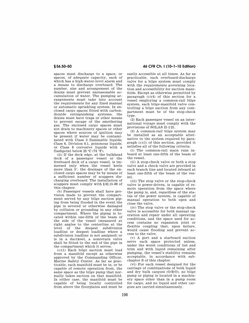
spaces must discharge to a space, or spaces, of adequate capacity, each of which has a high-water-level alarm and a means to discharge overboard. The number, size and arrangement of the drains must prevent unreasonable ac-cumulation of water. The pumping ar-rangements must take into account the requirements for any fixed manual or automatic sprinkling system. In en-closed cargo spaces fitted with carbon- dioxide extinguishing systems, the drains must have traps or other means to prevent escape of the smothering gas. The enclosed cargo spaces must not drain to machinery spaces or other spaces where sources of ignition may be present if water may be contami-nated with Class 3 flammable liquids; Class 6, Division 6.1, poisonous liquids; or Class 8 corrosive liquids with a flashpoint below 23 °C (74 °F).
(ii) If the deck edge, at the bulkhead deck of a passenger vessel or the freeboard deck of a cargo vessel, is im-mersed only when the vessel heels more than 5°, the drainage of the en-closed cargo spaces may be by means of a sufficient number of scuppers dis-charging overboard. The installation of scuppers must comply with § 42.15–60 of this chapter.
(b) Passenger vessels shall have pro-vision made to prevent the compart-ment served by any bilge suction pip-ing from being flooded in the event the pipe is severed or otherwise damaged by collision or grounding in any other compartment. Where the piping is lo-cated within one-fifth of the beam of the side of the vessel (measured at right angles to the centerline at the level of the deepest subdivision loadline or deepest loadline where a subdivision loadline is not assigned) or is in a ductkeel, a nonreturn valve shall be fitted to the end of the pipe in the compartment which it serves.
(c)(1) Each bilge suction must lead from a manifold except as otherwise approved by the Commanding Officer, Marine Safety Center. As far as prac-ticable, each manifold must be in, or be capable of remote operation from, the same space as the bilge pump that nor-mally takes suction on that manifold. In either case, the manifold must be capable of being locally controlled from above the floorplates and must be
easily accessible at all times. As far as practicable, each overboard-discharge valve for a bilge system must comply with the requirements governing loca-tion and accessibility for suction mani-folds. Except as otherwise permitted by paragraph (c)(4) of this section for a vessel employing a common-rail bilge system, each bilge-manifold valve con-trolling a bilge suction from any com-partment must be of the stop-check type.
(2) Each passenger vessel on an inter-national voyage must comply with the provisions of SOLAS II–1/21.
(3) A common-rail bilge system may be installed as an acceptable alter-native to the system required by para-graph (c)(1) of this section, provided it satisfies all of the following criteria:
(i) The common-rail main runs in-board at least one-fifth of the beam of the vessel.
(ii) A stop-check valve or both a stop valve and a check valve are provided in each branch line and located inboard at least one-fifth of the beam of the ves-sel.
(iii) The stop valve or the stop-check valve is power-driven, is capable of re-mote operation from the space where the pump is, and, regardless of the sta-tus of the power system, is capable of manual operation to both open and close the valve.
(iv) The stop valve or the stop-check valve is accessible for both manual op-eration and repair under all operating conditions, and the space used for ac-cess contains no expansion joint or flexible coupling that, upon failure, would cause flooding and prevent ac-cess to the valve.
(v) A port and a starboard suction serve each space protected unless, under the worst conditions of list and trim and with liquid remaining after pumping, the vessel’s stability remains acceptable, in accordance with sub-chapter S of this chapter.
(vi) For each vessel designed for the carriage of combinations of both liquid and dry bulk cargoes (O/B/O), no bilge pump or piping is located in a machin-ery space other than in a pump room for cargo, and no liquid and other car-goes are carried simultaneously.
VerDate Mar<15>2010 09:56 Dec 08, 2010 Jkt 220192 PO 00000 Frm 00208 Fmt 8010 Sfmt 8010 Y:\SGML\220192.XXX 220192jdjo
nes
on D
SK
8KY
BLC
1PR
OD
with
CF
R

199
Coast Guard, Dept. of Homeland Security § 56.50–50
(vii) For each cargo vessel in Great Lakes service, each common-rail pip-ing for the bilge and ballast system serving cargo spaces, if installed and if connected to a dedicated common-rail bilge system, must lead separately from a valved manifold located at the pump.
(d) The internal diameter of bilge suction pipes including strainers shall be determined by formulas (1) and (2), except that the nearest commercial size not more than one-fourth inch under the required diameter may be used. Bilge suction pipes shall be suit-ably faired to pump inlets.
(1) For suctions to each main bilge pump:
dL B D
= ++( ) ( ) ( ) ( )1
25001 4 5
(2) For branch suctions to cargo and machinery spaces:
d = 1+c B+ D( ) ( ) ( ) ( )
15002 3 5
where: L=Length of vessel on loadwater line, in feet. B=Breadth of vessel, in feet. (5) D=Molded depth (in feet) to the bulkhead
deck. (6) c=Length of compartment, in feet. d=Required internal diameter of suction
pipe, in inches.
NOTE 1. For tank vessels, ‘‘L’’ may be re-duced by the combined length of the cargo oil tanks.
NOTE 2. For bulk carriers with full depth wing tanks served by a ballast system where the beam of the vessel is not representative of the breadth of the compartment, ‘‘B’’ may be appropriately modified to the breadth of the compartment.
NOTE 3. In the calculation for a vessel with more than one hull, such as a catamaran, the breadth of the unit is the breadth of one hull.
NOTE 4. In the calculation for a mobile off-shore drilling unit, ‘‘L’’ is reducible by the combined length of spaces that can be pumped by another piping system meeting §§ 56.50–50 and 56.50–55, where ‘‘L’’ is the length of the unit at the waterline.
NOTE 5. For mobile offshore drilling units employing unusual hull forms, ‘‘B’’ may be modified to the average breadth rather than the maximum breadth.
NOTE 6. For each passenger vessel con-structed on or after June 9, 1995, and being on an international voyage, D must be meas-
ured to the next deck above the bulkhead deck if an enclosed cargo space on the bulk-head deck that is internally drained in ac-cordance with paragraph (a)(4) of this section extends the entire length of the vessel. Where the enclosed cargo space extends a lesser length, D must be taken as the sum of the molded depth (in feet) to the bulkhead deck plus lh/L where l and h are the aggre-gate length and height (in feet) of the en-closed cargo space.
(3) For vessels of 150 gross tons and over, no main suction piping shall be less than 21⁄2 inches internal diameter. Branch piping need not be more than 4 inches and shall not be less than 2 inches in diameter except for drainage of small pockets or spaces in which case 11⁄2-inch diameter may be used. For vessels less than 150 gross tons no bilge suction shall be less than 11⁄2 inches internal diameter and no branch piping shall be less than 1 inch nominal pipe size.
(4) For vessels of 65 feet in length or less and not engaged on an inter-national voyage, the bilge pipe sizes computed by Formulas (1) and (2) of this paragraph are not mandatory, but in no case shall the size be less than 1 inch nominal pipe size.
(5) The number, location, and size of bilge suctions in the boiler and ma-chinery compartments shall be deter-mined when the piping plans are sub-mitted for approval and shall be based upon the size of the compartments and the drainage arrangements.
(e) Independent bilge suction. One of the independent bilge pumps must have a suction of a diameter not less than that given by Formula (2) in paragraph (d) of this section that is led directly from the engine room bilge entirely independent of the bilge main, and on passenger vessels each independent bilge pump located in the machinery spaces must have such direct suctions from these spaces, except that not more than two pumps are required to have direct suctions from any one space. A suction that is led directly from a suitably located pump manifold may be considered to be independent of the bilge main. Where two direct suc-tions are required in any one compart-ment on passenger vessels, one suction must be located on each side of the compartment. If watertight bulkheads separate the engine and boiler rooms, a
VerDate Mar<15>2010 09:56 Dec 08, 2010 Jkt 220192 PO 00000 Frm 00209 Fmt 8010 Sfmt 8010 Y:\SGML\220192.XXX 220192 EC
01F
E91
.025
</M
AT
H>
EC
01F
E91
.026
</M
AT
H>
jdjo
nes
on D
SK
8KY
BLC
1PR
OD
with
CF
R
200
46 CFR Ch. I (10–1–10 Edition) § 56.50–50
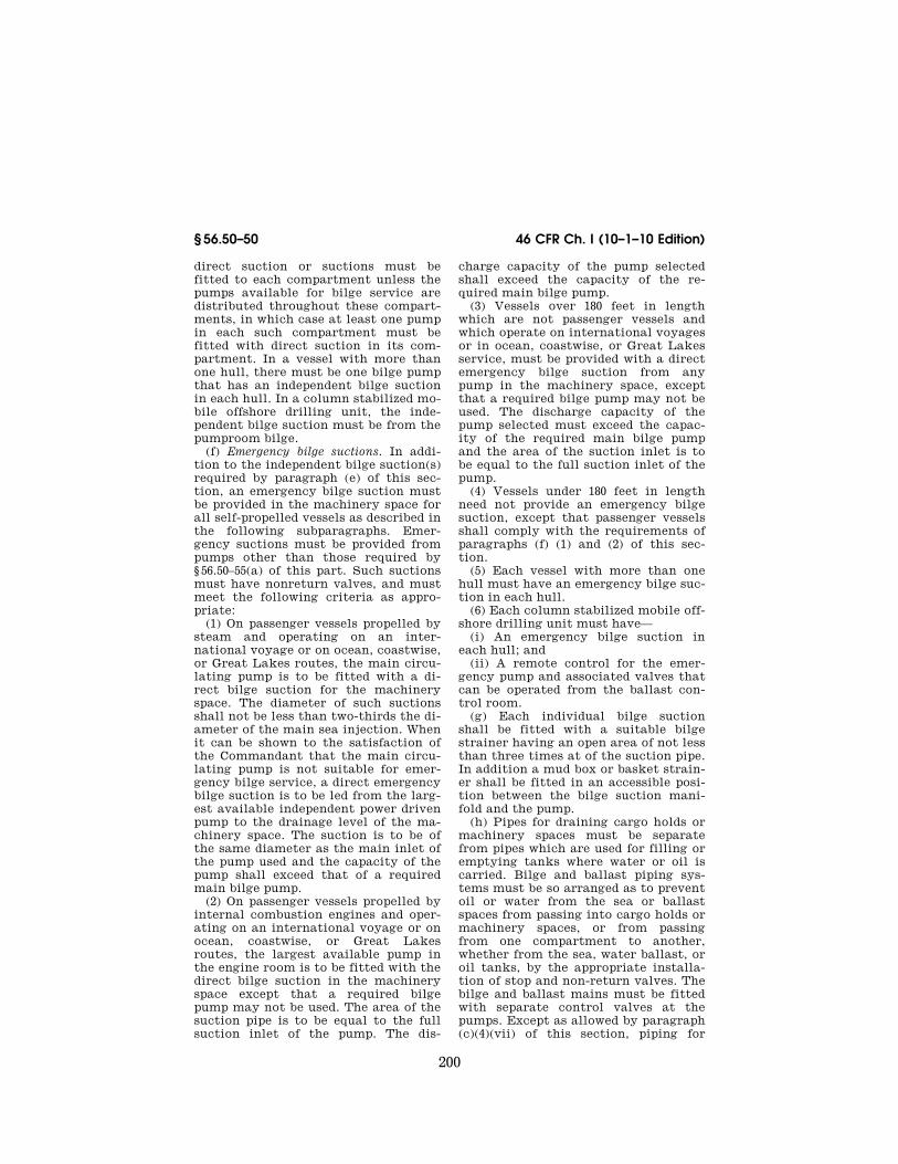
direct suction or suctions must be fitted to each compartment unless the pumps available for bilge service are distributed throughout these compart-ments, in which case at least one pump in each such compartment must be fitted with direct suction in its com-partment. In a vessel with more than one hull, there must be one bilge pump that has an independent bilge suction in each hull. In a column stabilized mo-bile offshore drilling unit, the inde-pendent bilge suction must be from the pumproom bilge.
(f) Emergency bilge suctions. In addi-tion to the independent bilge suction(s) required by paragraph (e) of this sec-tion, an emergency bilge suction must be provided in the machinery space for all self-propelled vessels as described in the following subparagraphs. Emer-gency suctions must be provided from pumps other than those required by § 56.50–55(a) of this part. Such suctions must have nonreturn valves, and must meet the following criteria as appro-priate:
(1) On passenger vessels propelled by steam and operating on an inter-national voyage or on ocean, coastwise, or Great Lakes routes, the main circu-lating pump is to be fitted with a di-rect bilge suction for the machinery space. The diameter of such suctions shall not be less than two-thirds the di-ameter of the main sea injection. When it can be shown to the satisfaction of the Commandant that the main circu-lating pump is not suitable for emer-gency bilge service, a direct emergency bilge suction is to be led from the larg-est available independent power driven pump to the drainage level of the ma-chinery space. The suction is to be of the same diameter as the main inlet of the pump used and the capacity of the pump shall exceed that of a required main bilge pump.
(2) On passenger vessels propelled by internal combustion engines and oper-ating on an international voyage or on ocean, coastwise, or Great Lakes routes, the largest available pump in the engine room is to be fitted with the direct bilge suction in the machinery space except that a required bilge pump may not be used. The area of the suction pipe is to be equal to the full suction inlet of the pump. The dis-
charge capacity of the pump selected shall exceed the capacity of the re-quired main bilge pump.
(3) Vessels over 180 feet in length which are not passenger vessels and which operate on international voyages or in ocean, coastwise, or Great Lakes service, must be provided with a direct emergency bilge suction from any pump in the machinery space, except that a required bilge pump may not be used. The discharge capacity of the pump selected must exceed the capac-ity of the required main bilge pump and the area of the suction inlet is to be equal to the full suction inlet of the pump.
(4) Vessels under 180 feet in length need not provide an emergency bilge suction, except that passenger vessels shall comply with the requirements of paragraphs (f) (1) and (2) of this sec-tion.
(5) Each vessel with more than one hull must have an emergency bilge suc-tion in each hull.
(6) Each column stabilized mobile off-shore drilling unit must have—
(i) An emergency bilge suction in each hull; and
(ii) A remote control for the emer-gency pump and associated valves that can be operated from the ballast con-trol room.
(g) Each individual bilge suction shall be fitted with a suitable bilge strainer having an open area of not less than three times at of the suction pipe. In addition a mud box or basket strain-er shall be fitted in an accessible posi-tion between the bilge suction mani-fold and the pump.
(h) Pipes for draining cargo holds or machinery spaces must be separate from pipes which are used for filling or emptying tanks where water or oil is carried. Bilge and ballast piping sys-tems must be so arranged as to prevent oil or water from the sea or ballast spaces from passing into cargo holds or machinery spaces, or from passing from one compartment to another, whether from the sea, water ballast, or oil tanks, by the appropriate installa-tion of stop and non-return valves. The bilge and ballast mains must be fitted with separate control valves at the pumps. Except as allowed by paragraph (c)(4)(vii) of this section, piping for
VerDate Mar<15>2010 09:56 Dec 08, 2010 Jkt 220192 PO 00000 Frm 00210 Fmt 8010 Sfmt 8010 Y:\SGML\220192.XXX 220192jdjo
nes
on D
SK
8KY
BLC
1PR
OD
with
CF
R

201
Coast Guard, Dept. of Homeland Security § 56.50–55
draining a cargo hold or machinery space must be separate from piping used for filling or emptying any tank where water or oil is carried. Piping for bilge and ballast must be arranged so as to prevent, by the appropriate in-stallation of stop and non-return valves, oil or water from the sea or bal-last spaces from passing into a cargo hold or machinery space, or from pass-ing from one compartment to another, regardless of the source. The bilge and ballast mains must be fitted with sepa-rate control valves at the pumps.
(i) Ballast piping shall not be in-stalled to any hull compartment of a wood vessel. Where the carriage of liq-uid ballast in such vessels is necessary, suitable ballast tanks, structurally independent of the hull, shall be pro-vided.
(j) When dry cargo is to be carried in deep tanks, arrangement shall be made for disconnecting or blanking-off the oil and ballast lines, and the bilge suc-tions shall be disconnected or blanked- off when oil or ballast is carried. Blind flanges or reversible pipe fittings may be employed for this purpose.
(k) Where bilge and ballast piping is led through tanks, except ballast pip-ing in ballast tanks, means must be provided to minimize the risk of flood-ing of other spaces due to pipe failure within the tanks. In this regard, such piping may be in an oiltight or water-tight pipe tunnel, or the piping may be of Schedule 80 pipe wall thickness, fitted with expansion bends, and all joints within the tanks are welded. Al-ternative designs may be installed as approved by the Marine Safety Center. Where a pipe tunnel is installed, the watertight integrity of the bulkheads must be maintained. No valve or fit-ting may be located within the tunnel if the pipe tunnel is not of sufficient size to afford easy access. These re-
quirements need not be met provided the contents of the tank and piping system are chemically compatible and strength and stability calculations are submitted showing that crossflooding resulting from a pipe, the tank, and the spaces through which the piping passes will not seriously affect the safety of the ship, including the launching of lifeboats due to the ship’s listing. Bilge lines led through tanks without a pipe tunnel must be fitted with nonreturn valves at the bilge suctions.
(l) When bilge pumps are utilized for other services, the piping shall be so arranged that under any condition at least one pump will be available for drainage of the vessel through an over-board discharge, while the other pump(s) are being used for a different service.
(m) All bilge pipes used in or under fuel storage tanks or in the boiler or machinery space, including spaces in which oil settling tanks or oil pumping units are located, shall be of steel or other acceptable material.
(n) Oil pollution prevention require-ments for bilge and ballast systems are contained in subpart B of part 155, Title 33, Code of Federal Regulations.
NOTE: For the purposes of this section, a pumproom is a machinery space on a column stabilized mobile offshore drilling unit.
[CGFR 68–82, 33 FR 18843, Dec. 18, 1968, as amended by CGFR 69–127, 35 FR 9979, June 17, 1970; CGD 73–58R, 39 FR 18767, May 30, 1974; 79–165a, 45 FR 64188, Sept. 29, 1980; CGD 77– 140, 54 FR 40608, Oct. 2, 1989; 55 FR 39968, Oct. 1, 1990; CGD 83–043, 60 FR 24772, May 10, 1995; CGD 95–028, 62 FR 51201, Sept. 30, 1997]
§ 56.50–55 Bilge pumps. (a) Self-propelled vessels. (1) Each self-
propelled vessel must be provided with a power-driven pump or pumps con-nected to the bilge main as required by Table 56.50–55(a).
TABLE 56.50–55(a)—POWER BILGE PUMPS REQUIRED FOR SELF-PROPELLED VESSELS
Vessel length, in feet
Passenger vessels 1 Dry-cargo vessels 2 Tank vessels
Mobile offshore drilling units Inter-
national voyages 3
Ocean, coast-
wise and Great Lakes
All other waters
Ocean, coast-
wise and Great Lakes
All waters All waters All waters
180′ or more .............................................. 4 3 4 3 2 2 2 2 2 Below 180′ and exceeding 65′ ................. 4 3 5 2 5 2 5 2 5 2 2 2
VerDate Mar<15>2010 09:56 Dec 08, 2010 Jkt 220192 PO 00000 Frm 00211 Fmt 8010 Sfmt 8010 Y:\SGML\220192.XXX 220192jdjo
nes
on D
SK
8KY
BLC
1PR
OD
with
CF
R

202
46 CFR Ch. I (10–1–10 Edition) § 56.50–55
TABLE 56.50–55(a)—POWER BILGE PUMPS REQUIRED FOR SELF-PROPELLED VESSELS—Continued
Vessel length, in feet
Passenger vessels 1 Dry-cargo vessels 2 Tank vessels
Mobile offshore drilling units Inter-
national voyages 3
Ocean, coast-
wise and Great Lakes
All other waters
Ocean, coast-
wise and Great Lakes
All waters All waters All waters
65′ or less ................................................. 3 1 1 1 1 1 ................
1 Small passenger vessels under 100 gross tons refer to Subpart 182.520 of Subchapter T (Small Passenger Vessel) of this chapter.
2 Dry-bulk carriers having ballast pumps connected to the tanks outside the engineroom and to the cargo hold may substitute the appropriate requirements for tank vessels.
3 Not applicable to passenger vessels which do not proceed more than 20 mile from the nearest land, or which are employed in the carriage of large numbers of unberthed passengers in special trades.
4 When the criterion numeral exceeds 30, an additional independent power-driven pump is required. (See Part 171 of this chapter for determination of criterion numeral.)
5 Vessels operating on lakes (including Great Lakes), bays, sounds, or rivers where steam is always available, or where a suit-able water supply is available from a power-driven pump of adequate pressure and capacity, may substitute siphons or eductors for one of the required power-driven pumps, provided a siphon or eductor is permanently installed in each hold or compartment.
(b) Nonself-propelled vessels. (1) Ocean going sailing vessels and barges shall be provided with pumps connected to
the bilge main as required in Table 56.50–55(b)(1).
TABLE 56.50–55(b)(1)—BILGE PUMPS REQUIRED FOR NONSELF-PROPELLED VESSELS
Type of vessel Waters navigated Power pumps (1) Hand pumps
Sailing ................................................. Ocean and coastwise ........................ Two .................................................... (2) Manned barges ................................... ......do ................................................. Two .................................................... (2) Manned barges ................................... Other than ocean and coastwise ...... (3) ....................................................... (3) Unmanned barges .............................. All waters ........................................... (3) ....................................................... (3) Mobile offshore drilling units ............... All waters ........................................... Two .................................................... None.
1 Where power is always available, independent power bilge pumps shall be installed as required and shall be connected to the bilge main.
2 Efficient hand pumps connected to the bilge main may be substituted for the power pumps. Where there is no common bilge main, one hand pump will be required for each compartment.
3 Suitable hand or power pumps or siphons, portable or fixed, carried either on board the barge or on the towing vessel shall be provided.
(2) The pumps and source of power for operation on oceangoing sailing vessels and barges shall be located above the bulkhead deck or at the highest con-venient level which is always acces-sible.
(3) Each hull of a vessel with more than one hull, such as a catamaran, must meet Table 56.50–55(b).
(c) Capacity of independent power bilge pump. Each power bilge pump must have the capacity to develop a suction velocity of not less than 400 feet per minute through the size of bilge main piping required by § 56.50–50(d)(1) of this part under ordinary conditions; except that, for vessels of less than 65 feet in length not engaged on international voyages, the pump must have a min-imum capacity of 25 gallons per minute and need not meet the velocity require-ment of this paragraph.
(d) Priming. Suitable means shall be provided for priming centrifugal pumps which are not of the self-priming type.
(e) Location. (1) For self-propelled vessels, if the engines and boilers are in two or more watertight compartments, the bilge pumps must be distributed throughout these compartments. On other self-propelled vessels and mobile offshore drilling units, the bilge pumps must be in separate compartments to the extent practicable. When the loca-tion of bilge pumps in separate water-tight compartments is not practicable, alternative arrangements may be sub-mitted for consideration by the Marine Safety Center.
(2) For nonself-propelled vessels re-quiring two bilge pumps, these pumps, insofar as practicable, shall be located in separate watertight machinery spaces. When the location of bilge
VerDate Mar<15>2010 09:56 Dec 08, 2010 Jkt 220192 PO 00000 Frm 00212 Fmt 8010 Sfmt 8010 Y:\SGML\220192.XXX 220192jdjo
nes
on D
SK
8KY
BLC
1PR
OD
with
CF
R

203
Coast Guard, Dept. of Homeland Security § 56.50–60
pumps in separate watertight compart-ments is not possible, the Commandant will consider alternate arrangements of the bilge pumps.
(3) The emergency bilge pumps shall not be installed in a passenger ship for-ward of the collision bulkhead.
(4) Each hull of a vessel with more than one hull must have at least two means for pumping the bilges in each hull. No multi-hulled vessel may oper-ate unless one of these means is avail-able to pump each bilge.
(f) Other pumps. Sanitary, ballast, and general service pumps having the required capacity may be accepted as independent power bilge pumps if fitted with the necessary connections to the bilge pumping system.
[CGFR 68–82, 33 FR 18843, Dec. 18, 1968, as amended by CGD 79–023, 48 FR 51007, Nov. 4, 1983; CGD 77–140, 54 FR 40608, Oct. 2, 1989; 55 FR 39968, Oct. 1, 1990; CGD 83–043, 60 FR 24773, May 10, 1995; USCG–2004–18884, 69 FR 58346, Sept. 30, 2004]
§ 56.50–57 Bilge piping and pumps, al-ternative requirements.
(a) If a passenger vessel complies with §§ 171.075 and 171.082 of this chap-ter, its bilge pumping and piping sys-tems must meet §§ 56.50–50 and 56.50–55, except as follows:
(1) Each bilge pumping system must comply with—
(i) Regulation 19(b) of the Annex to IMCO Resolution A.265 (VIII) in place of §§ 56.50–55(a)(1), 56.50–55(a)(3), and 56.50–55(f);
(ii) Regulation 19(d) of the Annex to IMCO Resolution A.265 (VIII) in place of § 56.50–55(a)(2).
(2) Each bilge main must comply with Regulation 19(i) of the Annex to IMCO Resolution A.265 (VIII) in place of § 56.50–50(d) except—
(i) The nearest commercial pipe size may be used if it is not more than one- fourth inch under the required diame-ter; and
(ii) Each branch pipe must comply with § 56.50–50(d)(2).
(b) The standards referred to in this section, which are contained in the Inter-governmental Maritime Consult-ative Organization (IMCO) Resolution A.265 (VIII), dated December 10, 1973, are incorporated by reference. This document is available from the Na-
tional Technical Information Service, Springfield, Virginia, 22151, under the title ‘‘Regulations on Subdivision and Stability of Passenger Ships as Equiva-lent to part B of chapter II of the Inter-national Convention for the Safety of Life at Sea, 1960’’ (Volume IV of the U.S. Coast Guard’s ‘‘Commandant’s International Technical Series’’, USCG CITS–74–1–1.)
[CGD 76–053, 47 FR 37553, Aug. 26, 1982, as amended by CGD 79–023, 48 FR 51007, Nov. 4, 1983]
§ 56.50–60 Systems containing oil. (a)(1) Oil-piping systems for the
transfer or discharge of cargo or fuel oil must be separate from other piping systems as far as practicable, and posi-tive means shall be provided to prevent interconnection in service.
(2) Fuel oil and cargo oil systems may be combined if the cargo oil sys-tems contain only Grade E oils and have no connection to cargo systems containing grades of oil with lower flash points or hazardous substances.
(3) Pumps used to transfer oil must have no discharge connections to fire mains, boiler feed systems, or con-densers unless approved positive means are provided to prevent oil from being accidentally discharged into any of the aforementioned systems.
(b) When oil needs to be heated to lower its viscosity, heating coils must be properly installed in each tank.
(1) Each drain from a heating coil as well as each drain from an oil heater must run to an open inspection tank or other suitable oil detector before re-turning to the feed system.
(2) As far as practicable, no part of the fuel-oil system containing heated oil under pressure exceeding 180 KPa (26 psi) may be placed in a concealed position so that defects and leakage cannot be readily observed. Each ma-chinery space containing a part of the system must be adequately illumi-nated.
(c) Filling pipes may be led directly from the deck into the tanks or to a manifold in an accessible location per-manently marked to indicate the tanks to which they are connected. A shutoff valve must be fitted at each filling end. Oil piping must not be led through ac-commodation spaces, except that low
VerDate Mar<15>2010 09:56 Dec 08, 2010 Jkt 220192 PO 00000 Frm 00213 Fmt 8010 Sfmt 8010 Y:\SGML\220192.XXX 220192jdjo
nes
on D
SK
8KY
BLC
1PR
OD
with
CF
R

204
46 CFR Ch. I (10–1–10 Edition) § 56.50–60
pressure fill piping not normally used at sea may pass through accommoda-tion spaces if it is of steel construc-tion, all welded, and not concealed.
(d) Piping subject to internal head pressure from oil in the tank must be fitted with positive shutoff valves lo-cated at the tank.
(1) Valves installed on the outside of the oil tanks must be made of steel, ductile cast iron ASTM A 395 (incor-porated by reference; see 46 CFR 56.01– 2), or a ductile nonferrous alloy having a melting point above 1,700 °F and must be arranged with a means of manual control locally at the valve and re-motely from a readily accessible and safe location outside of the compart-ment in which the valves are located.
(i) In the special case of a deep tank in any shaft tunnel, piping tunnel, or similar space, one or more valves must be fitted on the tank, but control in the event of fire may be effected by means of an additional valve on the piping outside the tunnel or similar space. Any such additional valve in-stalled inside a machinery space must be capable of being operated from out-side this space.
(ii) [Reserved] (2) If valves are installed on the in-
side of the tank, they may be made of cast iron and arranged for remote con-trol only. Additional valves for local control must be located in the space where the system exits from the tank or adjacent tanks. Valves for local con-trol outside the tanks must be made of steel, ductile cast iron ASTM A 395 , or a ductile nonferrous alloy having a melting point above 1,700 °F.
(3) Power operated valves installed to comply with the requirements of this section must meet the following re-quirements:
(i) Valve actuators must be capable of closing the valves under all condi-tions, except during physical interrup-tion of the power system (e.g., cable breakage or tube rupture). Fluid power actuated valves, other than those opened against spring pressure, must be provided with an energy storage sys-tem which is protected, as far as prac-ticable, from fire and collision. The storage system must be used for no other purpose and must have sufficient capacity to cycle all connected valves
from the initial valve position to the opposite position and return. The cross connection of this system to an alter-nate power supply will be given special consideration by the Marine Safety Center.
(ii) The valve shall have a local power actuator to both open and close the valve unless local manual opening operation will not prevent remote clos-ing of the valve.
(iii) The positioning of the valve by either the local or remote actuators shall not void the ability of the other actuator to close the valve.
(iv) The valve shall be provided with a means of emergency manual oper-ation to both open and close the valve regardless of the status of the power operating system. Such manual oper-ation may interfere with the power op-eration, and if so, shall be protected from causal use by means of covers, locking devices, or other suitable means. Instructions and warnings re-garding the emergency system shall be conspicuously posted at the valve.
(4) Remote operation for shutoff valves on small independent oil tanks will be specially considered in each case where the size of tanks and their location may warrant the omission of remote operating rods.
(e) Fuel oil tanks overhanging boilers are prohibited.
(f) Valves for drawing fuel or drain-ing water from fuel are not permitted in fuel oil systems except that a single valve may be permitted in the case of diesel driven machinery if suitably lo-cated within the machinery space away from any potential source of ignition. Such a valve shall be fitted with a cap or a plug to prevent leakage.
(g) Test cocks must not be fitted to fuel oil or cargo oil tanks.
(h) Oil piping must not run through feed or potable water tanks. Feed or potable water piping must not pass through oil tanks.
(i) Where flooding equalizing cross- connections between fuel or cargo tanks are required for stability consid-erations, the arrangement must be ap-proved by the Marine Safety Center.
(j) Piping conveying oil must be run well away from hot surfaces wherever possible. Where such leads are unavoid-able, only welded joints are to be used,
VerDate Mar<15>2010 09:56 Dec 08, 2010 Jkt 220192 PO 00000 Frm 00214 Fmt 8010 Sfmt 8010 Y:\SGML\220192.XXX 220192jdjo
nes
on D
SK
8KY
BLC
1PR
OD
with
CF
R
205
Coast Guard, Dept. of Homeland Security § 56.50–65
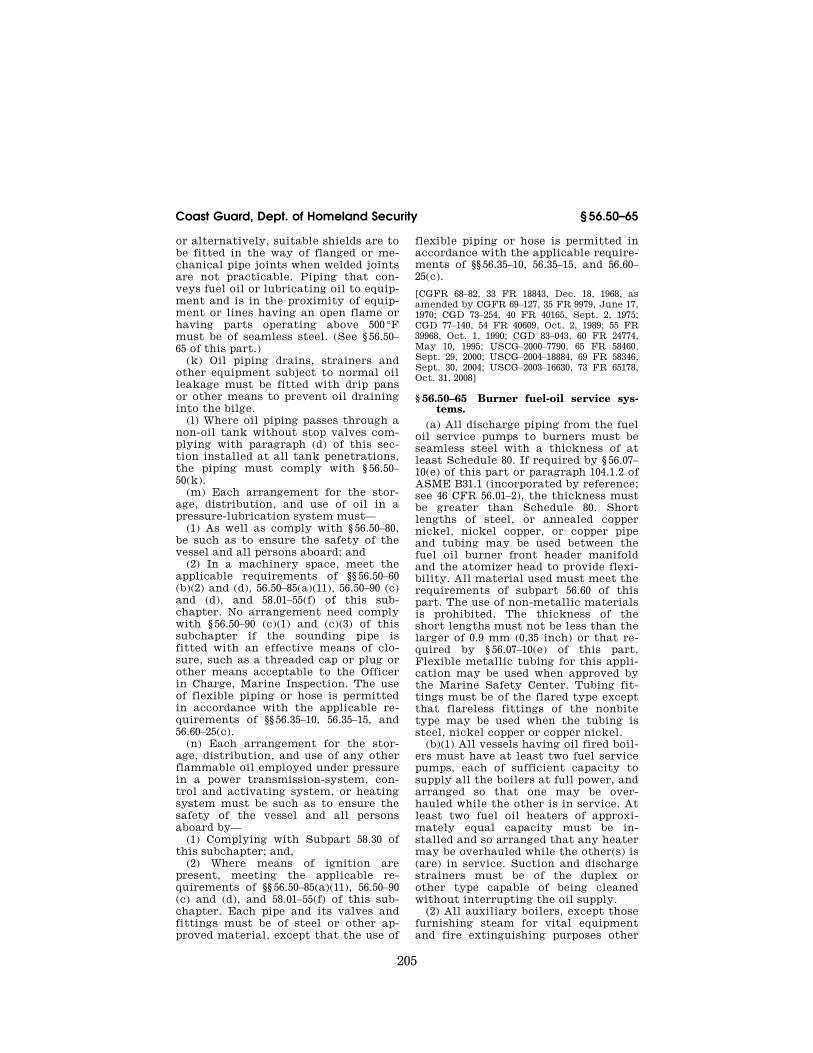
or alternatively, suitable shields are to be fitted in the way of flanged or me-chanical pipe joints when welded joints are not practicable. Piping that con-veys fuel oil or lubricating oil to equip-ment and is in the proximity of equip-ment or lines having an open flame or having parts operating above 500 °F must be of seamless steel. (See § 56.50– 65 of this part.)
(k) Oil piping drains, strainers and other equipment subject to normal oil leakage must be fitted with drip pans or other means to prevent oil draining into the bilge.
(l) Where oil piping passes through a non-oil tank without stop valves com-plying with paragraph (d) of this sec-tion installed at all tank penetrations, the piping must comply with § 56.50– 50(k).
(m) Each arrangement for the stor-age, distribution, and use of oil in a pressure-lubrication system must—
(1) As well as comply with § 56.50–80, be such as to ensure the safety of the vessel and all persons aboard; and
(2) In a machinery space, meet the applicable requirements of §§ 56.50–60 (b)(2) and (d), 56.50–85(a)(11), 56.50–90 (c) and (d), and 58.01–55(f) of this sub-chapter. No arrangement need comply with § 56.50–90 (c)(1) and (c)(3) of this subchapter if the sounding pipe is fitted with an effective means of clo-sure, such as a threaded cap or plug or other means acceptable to the Officer in Charge, Marine Inspection. The use of flexible piping or hose is permitted in accordance with the applicable re-quirements of §§ 56.35–10, 56.35–15, and 56.60–25(c).
(n) Each arrangement for the stor-age, distribution, and use of any other flammable oil employed under pressure in a power transmission-system, con-trol and activating system, or heating system must be such as to ensure the safety of the vessel and all persons aboard by—
(1) Complying with Subpart 58.30 of this subchapter; and,
(2) Where means of ignition are present, meeting the applicable re-quirements of §§ 56.50–85(a)(11), 56.50–90 (c) and (d), and 58.01–55(f) of this sub-chapter. Each pipe and its valves and fittings must be of steel or other ap-proved material, except that the use of
flexible piping or hose is permitted in accordance with the applicable require-ments of §§ 56.35–10, 56.35–15, and 56.60– 25(c).
[CGFR 68–82, 33 FR 18843, Dec. 18, 1968, as amended by CGFR 69–127, 35 FR 9979, June 17, 1970; CGD 73–254, 40 FR 40165, Sept. 2, 1975; CGD 77–140, 54 FR 40609, Oct. 2, 1989; 55 FR 39968, Oct. 1, 1990; CGD 83–043, 60 FR 24774, May 10, 1995; USCG–2000–7790, 65 FR 58460, Sept. 29, 2000; USCG–2004–18884, 69 FR 58346, Sept. 30, 2004; USCG–2003–16630, 73 FR 65178, Oct. 31, 2008]
§ 56.50–65 Burner fuel-oil service sys-tems.
(a) All discharge piping from the fuel oil service pumps to burners must be seamless steel with a thickness of at least Schedule 80. If required by § 56.07– 10(e) of this part or paragraph 104.1.2 of ASME B31.1 (incorporated by reference; see 46 CFR 56.01–2), the thickness must be greater than Schedule 80. Short lengths of steel, or annealed copper nickel, nickel copper, or copper pipe and tubing may be used between the fuel oil burner front header manifold and the atomizer head to provide flexi-bility. All material used must meet the requirements of subpart 56.60 of this part. The use of non-metallic materials is prohibited. The thickness of the short lengths must not be less than the larger of 0.9 mm (0.35 inch) or that re-quired by § 56.07–10(e) of this part. Flexible metallic tubing for this appli-cation may be used when approved by the Marine Safety Center. Tubing fit-tings must be of the flared type except that flareless fittings of the nonbite type may be used when the tubing is steel, nickel copper or copper nickel.
(b)(1) All vessels having oil fired boil-ers must have at least two fuel service pumps, each of sufficient capacity to supply all the boilers at full power, and arranged so that one may be over-hauled while the other is in service. At least two fuel oil heaters of approxi-mately equal capacity must be in-stalled and so arranged that any heater may be overhauled while the other(s) is (are) in service. Suction and discharge strainers must be of the duplex or other type capable of being cleaned without interrupting the oil supply.
(2) All auxiliary boilers, except those furnishing steam for vital equipment and fire extinguishing purposes other
VerDate Mar<15>2010 09:56 Dec 08, 2010 Jkt 220192 PO 00000 Frm 00215 Fmt 8010 Sfmt 8010 Y:\SGML\220192.XXX 220192jdjo
nes
on D
SK
8KY
BLC
1PR
OD
with
CF
R

206
46 CFR Ch. I (10–1–10 Edition) § 56.50–70
than duplicate installations, may be equipped with a single fuel oil service pump and a single fuel oil heater. Such pumps need not be fitted with dis-charge strainers.
(3) Strainers must be located so as to preclude the possibility of spraying oil on the burner or boiler casing, or be provided with spray shields. Coamings, drip pans, etc., must be fitted under fuel oil service pumps, heaters, etc., where necessary to prevent oil drain-age to the bilge.
(4) Boilers burning fuel oils of low viscosity need not be equipped with fuel oil heaters, provided acceptable evidence is furnished to indicate that satisfactory combustion will be ob-tained without the use of heaters.
(c) Piping between service pumps and burners shall be located so as to be readily observable, and all bolted flange joints shall be provided with a wrap around deflector to deflect spray in case of a leak. The relief valve lo-cated at the pump and the relief valves fitted to the fuel oil heaters shall dis-charge back into the settling tank or the suction side of the pump. The re-turn line from the burners shall be so arranged that the suction piping can-not be subjected to discharge pressure.
(d) If threaded-bonnet valves are em-ployed, they shall be of the union-bon-net type capable of being packed under pressure.
(e) Unions shall not be used for pipe diameters of 1 inch and above.
(f) Boiler header valves of the quick closing type shall be installed in the fuel supply lines as close to the boiler front header as practicable. The loca-tion is to be accessible to the operator or remotely controlled.
(g) Bushings and street ells are not permitted in fuel oil discharge piping.
(h) Each fuel-oil service pump must be equipped with controls as required by § 58.01–25 of this subchapter.
[CGFR 68–82, 33 FR 18843, Dec. 18, 1968, as amended by CGFR 69–127, 35 FR 9978, June 17, 1970; CGD 77–140, 54 FR 40609, Oct. 2, 1989; CGD 83–043, 60 FR 24774, May 10, 1995; USCG– 2003–16630, 73 FR 65178, Oct. 31, 2008]
§ 56.50–70 Gasoline fuel systems. (a) Material. (1) Fuel supply piping to
the engines shall be of seamless drawn annealed copper pipe or tubing, nickel
copper, or copper nickel pipe or tubing meeting the requirements of subpart 56.60.
(2) Thicknesses of tubing walls must not be less than the larger of that shown in Table 56.50–70(a) of this sec-tion or that required by 46 CFR 56.07– 10(e) and 104.1.2 of ASME B31.1 (incor-porated by reference; see 46 CFR 56.01– 2).
(3) Tubing fittings shall be of non-ferrous drawn or forged metal and of the flared type except that the flareless fittings of the nonbite type may be used when the tubing system is of nick-el copper or copper nickel. Tubing shall be cut square and flared by suitable tools. Tube ends shall be annealed be-fore flaring. Pipe fittings shall be of nonferrous material. Pipe thread joints shall be made tight with a suitable compound.
(4) Valves for fuel lines shall be of nonferrous material of the union bon-net type with ground seats except that cocks may be used if they are the solid bottom type with tapered plugs and union bonnets.
TABLE 56.50–70(a)—TUBING WALL THICKNESS
Outside diameter of tubing in inches Thickness
B.W.G. Inch
1⁄8, 3⁄16, 1⁄4 .......................................... #21 0.032 5⁄16, 3⁄8 ................................................ #20 .035 7⁄16, 1⁄2 ................................................ #19 .042
(b) Installation. (1) All fuel pipes, pipe connections, and accessories shall be readily accessible. The piping shall run in sight wherever practicable, pro-tected against mechanical injury, and effectively secured against excessive movement and vibration by the use of soft nonferrous metal liners or straps without sharp edges. Where passing through steel decks or bulkheads, fuel lines shall be protected by close fitting ferrules or stuffing boxes. Refer to § 56.30–25 for tubing joint installations.
(2) Either a short length of suitable metallic or nonmetallic flexible tubing or hose or a loop of annealed copper tubing must be installed in the fuel- supply line at or near the engine to prevent damage by vibration.
(i) If nonmetallic flexible hose is used, it must meet the requirements of 46 CFR 56.60–25(b) for fuel service.
VerDate Mar<15>2010 09:56 Dec 08, 2010 Jkt 220192 PO 00000 Frm 00216 Fmt 8010 Sfmt 8010 Y:\SGML\220192.XXX 220192jdjo
nes
on D
SK
8KY
BLC
1PR
OD
with
CF
R
207
Coast Guard, Dept. of Homeland Security § 56.50–75
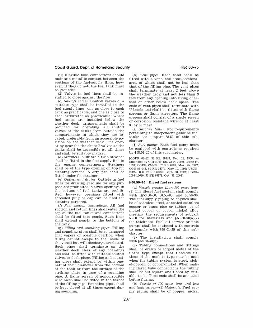
(ii) Flexible hose connections should maintain metallic contact between the sections of the fuel-supply lines; how-ever, if they do not, the fuel tank must be grounded.
(3) Valves in fuel lines shall be in-stalled to close against the flow.
(c) Shutoff valves. Shutoff valves of a suitable type shall be installed in the fuel supply lines, one as close to each tank as practicable, and one as close to each carburetor as practicable. Where fuel tanks are installed below the weather deck, arrangements shall be provided for operating all shutoff valves at the tanks from outside the compartments in which they are lo-cated, preferably from an accessible po-sition on the weather deck. The oper-ating gear for the shutoff valves at the tanks shall be accessible at all times and shall be suitably marked.
(d) Strainers. A suitable twin strainer shall be fitted in the fuel supply line in the engine compartment. Strainers shall be of the type opening on top for cleaning screens. A drip pan shall be fitted under the strainer.
(e) Outlets and drains. Outlets in fuel lines for drawing gasoline for any pur-pose are prohibited. Valved openings in the bottom of fuel tanks are prohib-ited; however, openings fitted with threaded plug or cap can be used for cleaning purposes.
(f) Fuel suction connections. All fuel suction and return lines shall enter the top of the fuel tanks and connections shall be fitted into spuds. Such lines shall extend nearly to the bottom of the tank.
(g) Filling and sounding pipes. Filling and sounding pipes shall be so arranged that vapors or possible overflow when filling cannot escape to the inside of the vessel but will discharge overboard. Such pipes shall terminate on the weather deck clear of any coamings and shall be fitted with suitable shutoff valves or deck plugs. Filling and sound-ing pipes shall extend to within one- half of their diameter from the bottom of the tank or from the surface of the striking plate in case of a sounding pipe. A flame screen of noncorrodible wire mesh shall be fitted in the throat of the filling pipe. Sounding pipes shall be kept closed at all times except dur-ing sounding.
(h) Vent pipes. Each tank shall be fitted with a vent, the cross-sectional area of which shall not be less than that of the filling pipe. The vent pipes shall terminate at least 2 feet above the weather deck and not less than 3 feet from any opening into living quar-ters or other below deck space. The ends of vent pipes shall terminate with U-bends and shall be fitted with flame screens or flame arresters. The flame screens shall consist of a single screen of corrosion resistant wire of at least 30 by 30 mesh.
(i) Gasoline tanks. For requirements pertaining to independent gasoline fuel tanks see subpart 58.50 of this sub-chapter.
(j) Fuel pumps. Each fuel pump must be equipped with controls as required by § 58.01–25 of this subchapter.
[CGFR 68–82, 33 FR 18843, Dec. 18, 1968, as amended by CGFR 69–127, 35 FR 9978, June 17, 1970; CGFR 72–59R, 37 FR 6189, Mar. 25, 1972; CGD 83–043, 60 FR 24774, May 10, 1995; USCG– 2002–13058, 67 FR 61278, Sept. 30, 2002; USCG– 2003–16630, 73 FR 65178, Oct. 31, 2008]
§ 56.50–75 Diesel fuel systems.
(a) Vessels greater than 100 gross tons. (1) The diesel fuel system shall comply with §§ 56.50–60, 56.50–85, and 56.50–90. The fuel supply piping to engines shall be of seamless steel, annealed seamless copper or brass pipe or tubing, or of nickel copper or copper nickel alloy meeting the requirements of subpart 56.60 for materials and § 56.50–70(a)(2) for thickness. Fuel oil service or unit pumps shall be equipped with controls to comply with § 58.01–25 of this sub-chapter.
(2) The installation shall comply with § 56.50–70(b).
(3) Tubing connections and fittings shall be drawn or forged metal of the flared type except that flareless fit-tings of the nonbite type may be used when the tubing system is steel, nick-el-copper, or copper-nickel. When mak-ing flared tube connections the tubing shall be cut square and flared by suit-able tools. Tube ends shall be annealed before flaring.
(b) Vessels of 100 gross tons and less and tank barges—(1) Materials. Fuel sup-ply piping shall be of copper, nickel
VerDate Mar<15>2010 09:56 Dec 08, 2010 Jkt 220192 PO 00000 Frm 00217 Fmt 8010 Sfmt 8010 Y:\SGML\220192.XXX 220192jdjo
nes
on D
SK
8KY
BLC
1PR
OD
with
CF
R

208
46 CFR Ch. I (10–1–10 Edition) § 56.50–80
copper or copper nickel having a min-imum wall thickness of 0.035 inch ex-cept that piping of other materials such as seamless steel pipe or tubing which provides equivalent safety may be used.
(2) Tubing connections and fittings. Tubing connections shall comply with the provisions of § 56.50–75(a)(3).
(3) Installation. The installation of diesel fuel piping shall comply with the requirements of § 56.50–70(b).
(4) Shutoff valves. Shutoff valves shall be installed in the fuel supply lines, one as close to each tank as prac-ticable, and one as close to each fuel pump as practicable. Valves shall be accessible at all times.
(5) Outlets and drains. Valves for re-moving water or impurities from fuel oil systems will be permitted in the machinery space provided such valves are fitted with caps or plugs to prevent leakage.
(6) Filling pipe. Tank filling pipes on motorboats and motor vessels of less than 100 gross tons and tank barges shall terminate on an open deck and shall be fitted with suitable shutoff valves, deck plugs, or caps.
(7) Vent pipes. Each tank shall be fitted with a vent pipe complying with § 56.50–85.
(8) Independent diesel fuel tanks. See subpart 58.50 of this subchapter for spe-cific requirements.
[CGFR 68–82, 33 FR 18843, Dec. 18, 1968, as amended by CGD 77–140, 54 FR 40610, Oct. 2, 1989]
§ 56.50–80 Lubricating-oil systems. (a) The lubricating oil system shall
be designed to function satisfactorily when the vessel has a permanent 15° list and a permanent 5° trim.
(b) When pressure or gravity-forced lubrication is employed for the steam driven main propelling machinery, an independent auxiliary lubricating pump shall be provided.
(c) Oil coolers on steam driven ma-chinery shall be provided with two sep-arate means of circulating water through the coolers.
(d) For internal combustion engine installations, the requirements of para-graphs (b) and (c) of this section shall be met, but they do not apply to ves-sels in river and harbor service, nor to
any vessel below 300 gross tons. Where the size and design of an engine is such that lubrication before starting is not necessary and an attached pump is nor-mally used, the independent auxiliary pump is not required if a duplicate of the attached pump is carried as spare. In meeting the requirements of para-graph (c) of this section in the case of internal combustion engines, two sepa-rate means are to be provided for circu-lating coolant on those engines on which oil coolers are fitted. One of those means must be independently driven and may consist of a connection from a pump of adequate size normally used for other purposes utilizing the re-quired coolant. Where the design of an engine will not readily accommodate an independent pump connection, the independent auxiliary pump will not be required if a duplicate of the attached pump is carried as a spare. Oil filters shall be provided on all internal com-bustion engine installations. On main propulsion engines which are fitted with full-flow type filters, the arrange-ment shall be such that the filters may be cleaned without interrupting the oil supply except that such an arrange-ment is not required on vessels having more than a single main propulsion en-gine.
(e) The lubricating oil piping shall be independent of other piping systems and shall be provided with necessary coolers, heaters, filters, etc., for proper operation. Oil heaters shall be fitted with bypasses.
(f) Diesel engine lubrication systems shall be so arranged that vapors from the sump tank may not be discharged back into the engine crank case of en-gines of the dry sump type.
(g) Steam turbine driven propulsion and auxiliary generating machinery de-pending on forced lubrication shall be arranged to shut down automatically upon failure of the lubricating system.
(h) Sight-flow glasses may be used in lubricating-oil systems provided it has been demonstrated, to the satisfaction of the Commanding Officer, Marine Safety Center, that they can withstand exposure to a flame at a temperature of 927 °C (1700 °F) for one hour, without failure or appreciable leakage.
VerDate Mar<15>2010 09:56 Dec 08, 2010 Jkt 220192 PO 00000 Frm 00218 Fmt 8010 Sfmt 8010 Y:\SGML\220192.XXX 220192jdjo
nes
on D
SK
8KY
BLC
1PR
OD
with
CF
R

209
Coast Guard, Dept. of Homeland Security § 56.50–85
(i) Steam driven propulsion machin-ery must be provided with an emer-gency supply of lubricating oil that must operate automatically upon fail-ure of the lubricating oil system. The emergency oil supply must be adequate to provide lubrication until the equip-ment comes to rest during automatic shutdown.
[CGFR 68–82, 33 FR 18843, Dec. 18, 1968, as amended by CGFR 69–127, 35 FR 9979, June 17, 1970; CGD 81–030, 53 FR 17837, May 18, 1988; CGD 83–043, 60 FR 24774, May 10, 1995]
§ 56.50–85 Tank-vent piping. (a) This section applies to vents for
all independent, fixed, non-pressure tanks or containers or for spaces in which liquids, such as fuel, ship’s stores, cargo, or ballast, are carried.
(1) The structural arrangement in double bottom and other tanks shall be such as to permit the free passage of air and gases from all parts of the tanks to vent pipes.
(2) Tanks having a comparatively small surface, such as fuel oil settling tanks, need be fitted with only one vent pipe, but tanks having a compara-tively large surface shall be fitted with at least two vent pipes. The vents shall be located so as to provide venting of the tanks under any service condition.
(3) Vent pipes for fuel oil tanks shall, wherever possible, have a slope of no less than 30°. Header lines, where both ends are adequately drained to a tank, are excluded from this requirement.
(4) Tank vents must extend above the weather deck, except vents from fresh water tanks, bilge oily-water holding tanks, bilge slop tanks, and tanks con-taining Grade E combustible liquids, such as lubricating oil, may terminate in the machinery space, provided—
(i) The vents are arranged to prevent overflow on machinery, electrical equipment, and hot surfaces;
(ii) Tanks containing combustible liquids are not heated; and
(iii) The vents terminate above the deep load waterline if the tanks have boundaries in common with the hull.
(5) Vents from oil tanks must termi-nate not less than three feet from any opening into living quarters.
(6) Vents extending above the freeboard deck or superstructure deck from fuel oil and other tanks must be
at least Schedule 40 in wall thickness. Except for barges in inland service and for Great Lakes vessels, the height from the deck to any point where water may gain access through the vent to below deck must be at least 30 inches (760mm) on the freeboard deck and 171⁄2 inches (450mm) on the super-structure deck. On Great Lakes ves-sels, the height from the deck to any point where water may gain access through the vent to below deck must be at least 30 inches (760mm) on the freeboard deck, 24 inches (610mm) on the raised quarterdeck, and 12 inches (305mm) on other superstructure decks. Where the height of vents on Great Lakes vessels may interfere with the working of the vessel, a lower height may be approved by the Marine Safety Center provided the vent cap is prop-erly protected from mechanical dam-age. For barges in inland service, the vents must extend at least six inches above the deck. A lesser amount may be approved by the Marine Safety Cen-ter if evidence is provided that a par-ticular vent has proven satisfactory in service.
(7) Satisfactory means, permanently attached, shall be provided for closing the openings of all vents, except that barges in inland service may be ex-empted. Acceptable means of closure are:
(i) A ball check valve where the ball float, normally in the open position, will float up and close under the action of a submerging wave. The valve shall be designed so that the effective clear discharge area through the valve with the float in the open position is not less than the inlet area of the vent pipe to which the valve is connected.
(ii) A hinged closure normally open on the outlet of the return bend, which must close automatically by the force of a submerging wave; or
(iii) Another suitable device accept-able to the Commanding Officer, Ma-rine Safety Center.
(8) Vent outlets from all tanks which may emit flammable or combustible vapors, such as bilge slop tanks and contaminated drain tanks, must be fitted with a single screen of corrosion- resistant wire of at least 30 by 30 mesh, or two screens of at least 20 by 20 mesh spaced not less than one-half inch
VerDate Mar<15>2010 09:56 Dec 08, 2010 Jkt 220192 PO 00000 Frm 00219 Fmt 8010 Sfmt 8010 Y:\SGML\220192.XXX 220192jdjo
nes
on D
SK
8KY
BLC
1PR
OD
with
CF
R
210
46 CFR Ch. I (10–1–10 Edition) § 56.50–90
(13mm) nor more than 11⁄2 inches (38mm) apart. The clear area through the mesh must not be less than the in-ternal unobstructed area of the re-quired pipe.
(9) Where vents are provided with flame screens, the closure device shall be situated so as not to damage these screens.
(10) The diameter of each vent pipe must not be less than 11⁄2 inches nomi-nal pipe size for fresh water tanks, 2 inches nominal pipe size for water bal-last tanks, and 21⁄2 inches nominal pipe size for fuel oil tanks, except that small independent tanks need not have a vent more than 25% greater in cross- sectional area than the fill line.
(11)(i) If a tank may be filled by a pressure head exceeding that for which the tank is designed, the aggregate cross-sectional area of the vents in each tank must be not less than the cross-sectional area of the filling line unless the tank is protected by over-flows, in which case the aggregate cross-sectional area of the overflows must be not less than the cross-sec-tional area of the filling line.
(ii) Provision must be made to guard against liquids rising in the venting system to a height that would exceed the design head of a cargo tank or fuel- oil tank. It may be made by high-level alarms or overflow-control systems or other, equivalent means, together with gauging devices and procedures for fill-ing cargo tanks.
(12) Where deep tanks are intended for the occasional carriage of dry or liquid cargo, a ‘‘spectacle’’ or ring and blank flange may be fitted in the over-flow pipe so arranged as not to inter-fere with venting when the tanks con-tain oil.
(13) Vents from fresh water or water ballast tanks shall not be connected to a common header with vents from oil or oily ballast tanks.
(b) Tank vents must remain within the watertight subdivision boundaries in which the tanks they vent are lo-cated. Where the structural configura-tion of a vessel makes meeting this re-quirement impracticable, the Marine Safety Center may permit a tank vent to penetrate a watertight subdivision bulkhead. All tank vents which pene-trate watertight subdivision bulkheads
must terminate above the weather deck.
[CGFR 68–82, 33 FR 18843, Dec. 18, 1968, as amended by CGD 77–140, 54 FR 40610, Oct. 2, 1989; CGD 83–043, 60 FR 24774, May 10, 1995; CGD 95–012, 60 FR 48050, Sept. 18, 1995]
§ 56.50–90 Sounding devices. (a) Each tank must be provided with
a suitable means of determining liquid level. Except for a main cargo tank on a tank vessel, each integral hull tank and compartment, unless at all times accessible while the vessel is operating, must be fitted with a sounding pipe.
(b) Where sounding pipes terminate below the freeboard deck on cargo ves-sels, they shall be fitted with gate valves. On passenger vessels, where sounding pipes terminate below the bulkhead deck, they shall be fitted with self-closing gate valves.
(c) Except as allowed by this para-graph, on each vessel constructed on or after June 9, 1995, no sounding pipe used in a fuel-oil tank may terminate in any space where the risk of ignition of spillage from the pipe might arise. None may terminate in a space for pas-sengers or crew. When practicable, none may terminate in a machinery space. When the Commanding Officer, Marine Safety Center, determines it impracticable to avoid terminating a pipe in a machinery space, a sounding pipe may terminate in a machinery space if all the following requirements are met:
(1) In addition to the sounding pipe, the fuel-oil tank has an oil-level gauge complying with paragraph (d) of this section.
(2) The pipe terminates in a place re-mote from ignition hazards unless pre-cautions are taken such as fitting an effective screen (shield) to prevent the fuel oil, in case of spillage through the end of the pipe, from coming into con-tact with a source of ignition.
(3) The end of the pipe is fitted with a self-closing blanking device and a small-diameter, self-closing control cock located below the blanking device for the purpose of ascertaining before the blanking device is opened that no fuel oil is present. Provision must be made to ensure that no spillage of fuel oil through the control cock involves an ignition hazard.
VerDate Mar<15>2010 09:56 Dec 08, 2010 Jkt 220192 PO 00000 Frm 00220 Fmt 8010 Sfmt 8010 Y:\SGML\220192.XXX 220192jdjo
nes
on D
SK
8KY
BLC
1PR
OD
with
CF
R

211
Coast Guard, Dept. of Homeland Security § 56.50–95
(d) On each vessel constructed on or after June 9, 1995, other oil-level gauges may be used instead of sounding pipes if all the following requirements are met:
(1) In a passenger vessel, no such gauge may require penetration below the top of the tank, and neither the failure of a gauge nor an overfilling of the tank may permit release of fuel into the space.
(2) In a cargo vessel, neither the fail-ure of such a gauge nor an overfilling of the tank may permit release of fuel into the space. The use of cylindrical gauge-glasses is prohibited. The use of oil-level gauges with flat glasses and self-closing valves between the gauges and fuel tanks is acceptable.
(e) The upper ends of sounding pipes terminating at the weather deck shall be closed by a screw cap or plug. Great Lakes dry cargo carriers may have the sounding pipes which service ballast water tanks terminate at least 4 inches above the deck if closure is provided by a tight fitting hinged cover making metal-to-metal contact with the hinge on the forward side. Positive means to secure these caps in the closed position shall be provided. Provision shall be made to prevent damage to the vessels’ plating by the striking of the sounding rod.
(f) On mobile offshore drilling units where installation of sounding pipes may not be practicable for some tanks, alternate means of determining liquid level may be used if approved by the Commandant.
[CGFR 68–82, 33 FR 18843, Dec. 18, 1968, as amended by CGD 73–251, 43 FR 56800, Dec. 4, 1978; CGD 83–043, 60 FR 24774, May 10, 1995; CGD 95–028, 62 FR 51201, Sept. 30, 1997]
§ 56.50–95 Overboard discharges and shell connections.
(a)(1) All inlets and discharges led through the vessel’s side shall be fitted with efficient and accessible means, lo-cated as close to the hull penetrations as is practicable, for preventing the ac-cidental admission of water into the vessel either through such pipes or in the event of fracture of such pipes.
(2) The number of scuppers, sanitary discharges, tank overflows, and other similar openings in the vessel’s side shall be reduced to a minimum, either
by making each discharge serve for as many as possible of the sanitary and other pipes, or in any other satisfac-tory manner.
(3) In general, when the bulkhead deck is above the freeboard deck, the requirements of this section apply rel-ative to the bulkhead deck. For vessels not assigned load lines, such as certain inland vessels and barges, the weather deck shall be taken as the freeboard deck.
(b)(1) Scuppers and discharge pipes originating at any level and pene-trating the shell either more than 171⁄2 inches (450mm) below the freeboard deck or less than 231⁄2 inches (600mm) above the summer load waterline must be provided with an automatic non-return valve at the shell. This valve, unless required by paragraph (b)(2) of this section, may be omitted if the pip-ing is not less than Schedule 80 in wall thickness for nominal pipe sizes through 8 inches, Schedule 60 for nomi-nal pipe sizes above 8 inches and below 16 inches, and Schedule 40 for nominal pipe sizes 16 inches and above.
(2) Discharges led through the shell originating either from spaces below the freeboard deck or from within en-closed superstructures and equivalent deckhouses on the freeboard deck as defined in § 42.13–15(i) of subchapter E (Load Lines) of this chapter, shall be fitted with efficient and accessible means for preventing water from pass-ing inboard. Normally each separate discharge shall have one automatic nonreturn valve with a positive means of closing it from a position above the freeboard deck. Where, however, the vertical upward distance from the sum-mer load line to the inboard end of the discharge pipe through which flooding can take place exceed 0.01L, the dis-charge may have two automatic non-return valves without positive means of closing, provided that the inboard valve is always accessible for examina-tion under service conditions. Where that vertical distance exceeds 0.02L a single automatic nonreturn valve with-out positive means of closing is accept-able. In an installation where the two automatic nonreturn valves are used, the inboard valve must be above the tropical load line. The means for oper-ating the positive action valve shall be
VerDate Mar<15>2010 09:56 Dec 08, 2010 Jkt 220192 PO 00000 Frm 00221 Fmt 8010 Sfmt 8010 Y:\SGML\220192.XXX 220192jdjo
nes
on D
SK
8KY
BLC
1PR
OD
with
CF
R

212
46 CFR Ch. I (10–1–10 Edition) § 56.50–95
readily accessible and provided with an indicator showing whether the valve is open or closed. A suitable arrangement shall be made to insure the valve is not closed by unauthorized persons, and a notice shall be posted in a conspicuous place at the operating station to the ef-fect that the valve shall not be closed except as required in an emergency.
(3) Where scuppers and drains are in-stalled in superstructures or deck-houses not enclosed as defined in § 42.13–15(j) of subchapter E (Load Lines) of this chapter, they shall be led overboard. Refer to paragraph (b)(1) of this section for any nonreturn valve re-quirement.
(4) Sanitary pump discharges leading directly overboard or via a holding tank must meet the standards pre-scribed by this paragraph. The location of the sanitary system openings within the vessel determines whether the re-quirements of paragraph (b)(2) or (3) of this section are applicable.
(c) Overflow pipes which discharge through the vessel’s side must be lo-cated as far above the deepest load line as practicable and fitted with valves as required by paragraph (b) of this sec-tion. Two automatic nonreturn valves must be used unless it is impracticable to locate the inboard valve in an acces-sible position, in which case a non-return valve with a positive means of closure from a position above the freeboard deck will be acceptable. Overflows which extend at least 30 inches above the freeboard deck before discharging overboard may be fitted with a single automatic nonreturn valve at the vessel’s side. Overflow pipes which serve as tank vents must not be fitted with positive means of closure without the specific approval of the Marine Safety Center. Overflow pipes may be vented to the weather.
(d)(1) Sea inlets and discharges, such as used in closed systems required for the operation of main and auxiliary machinery, as in pump connections or scoop injection heat exchanger connec-tions, need not meet the requirements of paragraphs (b) (1) and (2) of this sec-tion but instead shall be fitted with a shutoff valve located as near the shell plating as practicable, and may be lo-cally controlled if the valve is located in a manned machinery space. These
controls shall be readily accessible above the floor plates and shall be pro-vided with indication showing whether the valve is opened or closed. Manned machinery spaces include the main ma-chinery space and are either attended by the crew or are automated in ac-cordance with part 62 of this sub-chapter to be comparable to an at-tended space.
(2) In unmanned machinery spaces, all machinery inlets and discharges as described in paragraph (d)(1) of this section shall be remotely operable from a position above the freeboard deck unless otherwise approved and shall meet the access and marking re-quirements of paragraph (b)(2) of this section.
(e)(1) Pipes terminating at the shell plating shall be fitted with bends or el-bows between the outboard openings and the first rigid connection inboard. In no case shall such pipes be fitted in a direct line between the shell opening and the first inboard connection.
(2) Seachests and other hull fittings shall be of substantial construction and as short as possible. They shall be located as to minimize the possibility of being blocked or obstructed.
(3) The thickness of inlet and dis-charge connections outboard of the shutoff valves, and exclusive of seachests, must be not less than that of Schedule 80 for nominal pipe sizes through 8 inches, Schedule 60 for nomi-nal pipe sizes above 8 inches and below 16 inches, and Schedule 40 for nominal pipe sizes 16 inches and above.
(f) Valves required by this section and piping system components out-board of such required valves on new vessel installations or replacements in vessels of 150 gross tons and over shall be of a steel, bronze, or ductile cast iron specification listed in Table 56.60– 1(a). Lead or other heat sensitive mate-rials having a melting point of 1,700 °F. or less shall not be used in such serv-ice, or in any other application where the deterioration of the piping system in the event of fire would give rise to danger of flooding. Brittle materials such as cast iron shall not be used in such service. Where nonmetallic mate-rials are used in a piping system, and
VerDate Mar<15>2010 09:56 Dec 08, 2010 Jkt 220192 PO 00000 Frm 00222 Fmt 8010 Sfmt 8010 Y:\SGML\220192.XXX 220192jdjo
nes
on D
SK
8KY
BLC
1PR
OD
with
CF
R

213
Coast Guard, Dept. of Homeland Security § 56.50–96
shell closures are required by this sec-tion, a positive closure metallic valve is required (see also § 56.60–25).
(g) The inboard openings of ash and rubbish-chute discharges shall be fitted with efficient covers. If the inboard opening is located below the freeboard deck, the cover shall be watertight, and in addition, an automatic non-return valve shall be fitted in the chute in any easily accessible position above the deepest load line. Means shall be provided for securing both the cover and the valve when the chute is not in use. When ash-ejectors or similar ex-pelling devices located in the boiler-room have the inboard openings below the deepest load line, they shall be fitted with efficient means for pre-venting the accidental admission of water. The thickness of pipe for ash ejector discharge shall be not less than Schedule 80.
(h) Where deck drains, soil lines, and sanitary drains discharge through the shell in way of cargo tanks on tank vessels, the valves required by this sec-tion shall be located outside the cargo tanks. These valves shall meet the ma-terial requirements of paragraph (f) of this section. The piping led through such tanks shall be fitted with expan-sion bends where required, and shall be of steel pipe having a wall thickness of not less than five-eighths inch, except that the use of suitable corrosion-re-sistant material of lesser thickness will be given special consideration by the Commandant. All pipe joints with-in the tanks shall be welded. Soil lines and sanitary drains which pass through cargo tanks shall be provided with non-return valves with positive means of closing or other suitable means for pre-venting the entrance of gases into liv-ing quarters.
(i) Except as provided for in § 58.20– 20(c) of this chapter, sea valves must not be held open with locks. Where it is necessary to hold a discharge or intake closed with a lock, either a locking valve may be located inboard of the sea valve, or the design must be such that there is sufficient freedom of motion to fully close the locked sea valve after an event, such as fire damage to the seat, causes significant leakage through the valve. Valves which must be opened in and emergency, such as
bilge discharges or fire pump suctions must not be locked closed, whether they are sea valves or not.
[CGFR 68–82, 33 FR 18843; Dec. 18, 1968, as amended by CGFR 69–127, 35 FR 9979, June 17, 1970; CGFR 72–59R, 37 FR 6189, Mar. 25, 1972; CGD 81–030, 53 FR 17837, May 18, 1988; CGD 77– 140, 54 FR 40610, Oct. 2, 1989]
§ 56.50–96 Keel cooler installations.
(a) Keel cooler installations shall meet the requirements of § 56.50–95(d)(1) and (2), and (e)(3), and (f) except that shutoff or isolation valves will not be required for the inlet and discharge connections if:
(1) The installation is forward of the collision bulkhead; or,
(2) The installation is integral with the ship’s hull such that the cooler tubes are welded directly to the hull of the vessel with the hull forming part of the tube and satisfies all of the fol-lowing:
(i) The cooler structure is fabricated from material of the same thickness and quality as the hull plating to which it is attached except that in the case of half round pipe lesser thickness may be used if specifically approved by the Commandant. In any case the structure, with the exception of the hull proper, need not exceed three- eighths inch in thickness.
(ii) The flexible connections and all openings internal to the vessel, such as expansion tank vents and fills, in the installation are above the deepest load line and all piping components are Schedule 80 or thicker below the deep-est load line.
(iii) Full penetration welds are em-ployed in the fabrication of the struc-ture and its attachment to the hull.
(iv) The forward end of the structure must be faired to the hull such that the horizontal length of the fairing is no less than four times the height of the structure, or be in a protected location such as inside a bow thruster trunk.
[CGFR 68–82, 33 FR 18843, Dec. 18, 1968, as amended by CGFR 72–59R, 37 FR 6189, Mar. 25, 1972; CGD 77–140, 54 FR 40611, Oct. 2, 1989]
VerDate Mar<15>2010 09:56 Dec 08, 2010 Jkt 220192 PO 00000 Frm 00223 Fmt 8010 Sfmt 8010 Y:\SGML\220192.XXX 220192jdjo
nes
on D
SK
8KY
BLC
1PR
OD
with
CF
R

214
46 CFR Ch. I (10–1–10 Edition) § 56.50–97
§ 56.50–97 Piping for instruments, con-trol, and sampling (modifies 122.3).
(a) Piping for instruments, control, and sampling must comply with para-graph 122.3 of ASME B31.1 (incor-porated by reference; see 46 CFR 56.01– 2) except that:
(1) Soldered type fittings may not be used.
(2) The outside diameter of takeoff connections may not be less than 0.840 inches for service conditions up to 900 psi or 800 °F., and 1.050 inches for condi-tions that exceed either of these limits.
[CGFR 68–82, 33 FR 18843, Dec. 18, 1968, as amended by CGFR 69–127, 35 FR 9978, June 17, 1970; CGD 73–254, 40 FR 40165, Sept. 2, 1975; USCG–2003–16630, 73 FR 65178, Oct. 31, 2008]
§ 56.50–103 Fixed oxygen-acetylene dis-tribution piping.
(a) This section applies to fixed pip-ing installed for the distribution of ox-ygen and acetylene carried in cylinders as vessels stores.
(b) The distribution piping shall be of at least standard wall thickness and shall include a means, located as close to the supply cylinders as possible, of regulating the pressure from the sup-ply cylinders to the suitable pressure at the outlet stations.
(c) Acetylene distribution piping and pipe fittings must be seamless steel. Copper alloys containing less than 65 percent copper may be used in connec-tion with valves, regulators, gages, and other equipment used with acetylene.
(d) Oxygen distribution piping and pipe fittings must be seamless steel or copper.
(e) When more than two cylinders are connected to a manifold, the supply pipe between each cylinder and mani-fold shall be fitted with a non-return valve.
(f) Except for the cylinder manifolds, acetylene is not to be piped at a pres-sure in excess of 100 kPa (14.7 psi).
(g) Pipe joints on the low pressure side of the regulators shall be welded.
(h) Branch lines shall not run through unventilated spaces or accom-modation spaces.
(i) Relief valves or rupture discs shall be installed as relief devices in the pip-ing system if the maximum design pressure of the piping system can be exceeded. The relief device set pressure
shall not exceed the maximum design pressure of the piping system. Relief devices shall discharge to a location in the weather at least 3 m (10 ft) from sources of ignition or openings to spaces or tanks.
(j) Outlet stations are to be provided with suitable protective devices which will prevent the back flow of gas into the supply lines and prevent the pas-sage of flame into the supply lines.
(k) Shutoff valves shall be fitted at each outlet.
[CGD 95–028, 62 FR 51201, Sept. 30, 1997]
§ 56.50–105 Low-temperature piping. (a) Class I-L. Piping systems des-
ignated to operate at temperatures below 0 °F. and pressures above 150 pounds per square inch gage shall be of Class I-L. Exceptions to this rule may be found in the individual requirements for specific commodities in subchapters D, I, and O of this chapter. The fol-lowing requirements for Class I-L pip-ing systems shall be satisfied:
(1) Materials. All materials used in low temperature piping systems shall be selected from among those specifica-tions listed in Table 56.50–105 and shall satisfy all of the requirements of the specifications, except that:
(i) The minimum service temperature as defined in § 54.25–10(a)(2) of this sub-chapter shall not be colder than that shown in Table 56.50–105; and
(ii) The material shall be tested for low temperature toughness using the Charpy V-notch specimen of ASTM E 23 (incorporated by reference, see § 56.01–2), ‘‘Notched Bar Impact Testing of Metallic Materials’’, Type A, Figure 4. The toughness testing requirements of subpart 54.05 of this subchapter shall be satisfied for each particular product form. Charpy V-notch tests shall be conducted at temperatures not warmer than 10 °F. below the minimum service temperature of the design, except that for service temperatures of ¥320 °F. and below, the impact test may be con-ducted at the service temperature. The minimum average energy shall not be less than that shown in Table 56.50–105. In the case of steels conforming to the specifications of Table 54.25–20(a) of this subchapter the minimum lateral expansion shall not be less than that required in § 54.25–20 of this subchapter.
VerDate Mar<15>2010 09:56 Dec 08, 2010 Jkt 220192 PO 00000 Frm 00224 Fmt 8010 Sfmt 8010 Y:\SGML\220192.XXX 220192jdjo
nes
on D
SK
8KY
BLC
1PR
OD
with
CF
R

215
Coast Guard, Dept. of Homeland Security § 56.50–105
The minimum energy permitted for a single specimen and the minimum subsize energies shall be those obtained by multiplying the average energy shown in Table 56.50–105 by the applica-ble fraction shown in Table 56.50–105(a).
TABLE 56.50–105(a)—CHARPY V-NOTCH ENERGY MULTIPLYING FACTORS
Charpy V-notch specimen size 1
Factor for minimum
energy, av-erage of 3
specimens 1
Factor for minimum
energy sin-gle speci-
men 1
10×10 mm ................................. 1 2/3 10×7.5 mm ................................. 5/6 5/9 10×5.0 mm ................................. 2/3 4/9 10×2.5 mm ................................. 1/2 1/3
1 Straight line interpolation for intermediate values is permitted.
(iii) Steels equivalent to those listed in Table 56.50–105 of this part, but not produced according to a particular ASTM specification, may be used only with the prior consent of the Marine Safety Center. Steels differing in chemical composition, mechanical properties or heat treatments from those specified may be specially ap-proved by the Marine Safety Center. Similarly, aluminum alloys and other nonferrous materials not covered in Table 56.50–105 of this part may be spe-cifically approved by the Marine Safe-ty Center for service at any low tem-perature. There are restrictions on the use of certain materials in this part and in subchapter O of this chapter.
(2) Piping weldments. Piping weldments shall be fabricated to sat-isfy the requirements of § 57.03–1(b) of this subchapter in addition to subpart 56.70. Toughness testing of production weldments for low temperature piping systems and assemblies is not required.
(3) Postweld heat treatment. All piping weldments shall be postweld heat treated for stress relief in accordance with the procedures of subpart 56.85. The only exceptions to this require-ment are for materials which do not re-quire postweld heat treatment as shown in Table 56.85–10. Relief from postweld heat treatment shall not be dependent upon pipe thickness or weld joint type.
(4) Nonacceptable joints. Single welded butt joints with backing ring left in place, socket welds, slip-on flanges, pipe joining sleeves, and threaded
joints shall not be used, except in small diameter instrument lines.
(5) Other requirements. All other re-quirements of this part for Class I pip-ing apply to Class I-L piping. Pressure testing must comply with subpart 56.97 of this part, and nondestructive testing of circumferentially welded joints must comply with § 56.95–10. Seamless tubular products must be used except that, when the service pressure does not exceed 1724 KPa (250 psi), the Com-manding Officer, Marine Safety Center, may give special consideration to ap-propriate grades of piping and tubing that are welded without the addition of filler metal in the root pass. Each pro-duction procedure and quality-control program for welded products must be acceptable to the Officer in Charge, Marine Inspection.
(b) Class II-L. Piping systems de-signed to operate at temperatures below 0 °F. and pressures not higher than 150 pounds per square inch gage shall be of Class II-L. Exceptions to this rule may be found in the indi-vidual requirements for specific com-modities in subchapter D (Tank Ves-sels) and I (Cargo and Miscellaneous Vessels) of this chapter. The following requirements for Class II-L piping sys-tems shall be satisfied:
(1) Materials must be the same as those required by paragraph (a)(1) of this section except that pipe and tub-ing of appropriate grades welded with-out the addition of a filler metal may be used. The Commandant may give special consideration to tubular prod-ucts welded with the addition of filler metal.
(2) Piping weldments shall be fab-ricated to satisfy the requirements of § 57.03–1(b) of this subchapter in addi-tion to subpart 56.70. Toughness testing of production weldments for low tem-perature piping systems and assemblies is not required.
(3) All piping weldments shall be postweld heat treated for stress relief in accordance with the procedures of subpart 56.85. The only exceptions to this requirement are for materials which do not require postweld heat treatment as shown in Table 56.85–10 and for socket weld joints and slip-on flange weld attachments where the
VerDate Mar<15>2010 09:56 Dec 08, 2010 Jkt 220192 PO 00000 Frm 00225 Fmt 8010 Sfmt 8010 Y:\SGML\220192.XXX 220192jdjo
nes
on D
SK
8KY
BLC
1PR
OD
with
CF
R

216
46 CFR Ch. I (10–1–10 Edition) § 56.50–105
weld thickness does not exceed that ex-empted by this table. Otherwise, relief from post-weld heat treatment shall not be dependent upon pipe thickness or weld joint type.
(4) Socket welds in nominal sizes above 3 inches, slip-on flanges in nomi-nal sizes above 4 inches, and threaded joints in sizes above 1 inch shall not be used.
(5) Pressure testing must comply with Subpart 56.97, and nondestructive testing of welded joints must comply with § 56.95–10.
(6) All other requirements contained in this part for Class II piping shall be applicable to Class II-L systems, except that § 56.70–15(b)(3)(iv) shall not apply.
TABLE 56.50–105—ACCEPTABLE MATERIALS AND TOUGHNESS TEST CRITERIA 2
Product form ASTM specification 3 Grade 4 Minimum service tem-perature
Minimum avg Charpy V notch energy
Pipe .............................. 1 ................................... ¥30 °F ......................... 20 ft. lb. 3 ................................... ¥150 °F ....................... 25 ft. lb.
Tube (carbon and low A–333 and 4 (A–333 only) ............. ¥100 °F ....................... 25 ft. lb. alloy steels). A–334 ........................... 6 ................................... ¥30 °F ......................... 20 ft. lb.
7 ................................... ¥100 °F ....................... 25 ft. lb. 8 ................................... ¥320 °F ....................... Refer to § 54.25–20 of
this subchapter. Pipe (Austenitic stain-
less steel).A–312 ........................... All Grades .................... No limit ......................... Austenitic stainless
steel piping need be impact tested only when toughness tests are specified in subpart 54.25 of this subchapter for plating of the same alloy designation. When such toughness tests are required, the min-imum average en-ergy is 25 ft. lb.
Wrought welding fittings WPL1 ........................... ¥30 °F ......................... 20 ft. lb. (carbon and low alloy A–420 ........................... WPL3 ........................... ¥150 °F ....................... 25 ft. lb. steels). WPL4 ........................... ¥100 °F ....................... 25 ft. lb.
Forged or rolled flanges,
LF1 ............................... ¥30 °F ......................... 20 ft. lb.
forged fittings, valves A–350 1 ........................ LF2 ............................... ¥30 °F ......................... 20 ft. lb. and pressure parts LF3 ............................... ¥150 °F ....................... 25 ft. lb. (carbon and low alloy LF4 ............................... ¥100 °F ....................... 25 ft. lb. steels).
Forged or rolled flanges, forged fit-tings, valves and pressure parts (high alloy steels).
A–182 ........................... Austenitic grades only (304, 304H, 304L, 310, 316, 316H, 316L, 321, 321H, 347, 347H, 348, 348H).
No limit ......................... These products need be impact tested only when toughness tests are specified in subpart 54.25 of this subchapter for plating of the same alloy designation. When such toughness tests are required, the min-imum average en-ergy is 25 ft. lb.
Forged flanges, fittings, A–522 ........................... 9% Ni ........................... ¥320 °F ....................... Refer to § 54.25–20 of and valves (9% nick-el).
this subchapter.
Castings for valves and LCB .............................. ¥30 °F ......................... 20 ft. lb. pressure parts (car-bon
A–3521 ......................... LC1 .............................. ¥50 °F ......................... 20 ft. lb.
and low alloy steels). LC2 .............................. ¥100 °F ....................... 25 ft. lb. LC3 .............................. ¥150 °F ....................... 25 ft. lb.
Castings for valves and pressure parts (high alloy steel).
A–351 ........................... Austenitic grades CF3, CF3A, CF8, CF8A, CF3M, CF8M, CF8C, CK20 only.
No limit, except ¥325 °F for grades CF8C and CK20.
No toughness testing required except for service temperatures colder than ¥425 °F for grades CF3, CF3A, CF8, CF8A, CF3M, and CF8M. 25 ft. lb.
VerDate Mar<15>2010 09:56 Dec 08, 2010 Jkt 220192 PO 00000 Frm 00226 Fmt 8010 Sfmt 8010 Y:\SGML\220192.XXX 220192jdjo
nes
on D
SK
8KY
BLC
1PR
OD
with
CF
R

217
Coast Guard, Dept. of Homeland Security § 56.60–1
TABLE 56.50–105—ACCEPTABLE MATERIALS AND TOUGHNESS TEST CRITERIA 2—Continued
Product form ASTM specification 3 Grade 4 Minimum service tem-perature
Minimum avg Charpy V notch energy
average must be attained in these tests.
Bolting .......................... A–320 ........................... L7, L9, L10, L43 .......... ¥150 °F ....................... 20 ft. lb. B8D, B8T, B8F, B8M ... ¥325 °F ....................... No test required. 2B8, B8C ..................... No limit ......................... No test required, ex-
cept for service tem-peratures colder than ¥425 °F. In such case the minimum average energy is 25 ft. lb.
4 ................................... ¥150 °F ....................... 20 ft. lb. Nuts, bolting ................. A–194 ........................... 8T, 8F .......................... ¥325 °F ....................... No test required.
8, 8C ............................ No limit ......................... Same requirement as comparable grades (B8, B8C) of bolting listed above.
1 Quench and temper heat treatment may be permitted when specifically authorized by the Commandant. In those cases the minimum average Charpy V-notch energy shall be specially designated by the Commandant.
2 Other material specifications for product forms acceptable under part 54 for use at low temperatures may also be used for piping systems provided the applicable toughness requirements of this Table are also met.
3 Any repair method must be acceptable to the Commandant CG–521, and welding repairs as well as fabrication welding must be in accordance with part 57 of this chapter.
4 The acceptability of several alloys for low temperature service is not intended to suggest acceptable resistance to marine cor-rosion. The selection of alloys for any particular shipboard location must take corrosion resistance into account and be approved by the Marine Safety Center.
NOTE: The ASTM standards listed in table 56.50–105 are incorporated by reference; see 46 CFR 56.01–2.
[CGFR 68–82, 33 FR 18843, Dec. 18, 1968, as amended by CGFR 72–59R, 37 FR 6189, 6190, Mar. 25, 1972; CGD 73–254, 40 FR 40165, Sept. 2, 1975; CG 79–108, 43 FR 46545, Oct. 10, 1978; CGD 74– 289, 44 FR 26008, May 3, 1979; CGD 77–140, 54 FR 40611, Oct. 2, 1989; CGD 83–043, 60 FR 24775, May 10, 1995; USCG–2000–7790, 65 FR 58460, Sept. 29, 2000; USCG–2003–16630, 73 FR 65178, Oct. 31, 2008; USCG–2009–0702, 74 FR 49228, Sept. 25, 2009]
§ 56.50–110 Diving support systems.
(a) In addition to the requirements of this part, piping for diving installa-tions which is permanently installed on the vessel must meet the require-ments of subpart B (Commercial Div-ing Operations) of part 197 of this chap-ter.
(b) Piping for diving installations which is not permanently installed on the vessel need not meet the require-ments of this part, but must meet the requirements of subpart B of part 197 of this chapter.
(c) Piping internal to a pressure ves-sel for human occupancy (PVHO) need not meet the requirements of this part, but must meet the requirements of subpart B of part 197 of this chapter.
[CGD 76–009, 43 FR 53683, Nov. 16, 1978]
Subpart 56.60—Materials
§ 56.60–1 Acceptable materials and specifications (replaces 123 and Table 126.1 in ASME B31.1).
(a)(1) The material requirements in this subpart shall be followed in lieu of those in 123 in ASME B31.1 (incor-porated by reference; see 46 CFR 56.01– 2).
(2) Materials used in piping systems must be selected from the specifica-tions that appear in Table 56.60–1(a) of this section or 46 CFR 56.60–2, Table 56.60–2(a), or they may be selected from the material specifications of sections I or VIII of the ASME Boiler and Pres-sure Vessel Code (both incorporated by reference; see 46 CFR 56.01–2) if not pro-hibited by a regulation of this sub-chapter dealing with the particular
VerDate Mar<15>2010 09:56 Dec 08, 2010 Jkt 220192 PO 00000 Frm 00227 Fmt 8010 Sfmt 8010 Y:\SGML\220192.XXX 220192jdjo
nes
on D
SK
8KY
BLC
1PR
OD
with
CF
R