SUBORBITAL AND SPECIAL ORBITAL PROJECTS DIRECTORATE … · SUBORBITAL AND SPECIAL ORBITAL PROJECTS...
35
National Aeronautics and Space Administration 802-HDBK-0001D SUBORBITAL AND SPECIAL ORBITAL PROJECTS DIRECTORATE Doing Business at Wallops Flight Facility A Customer Guide Version D Effective June 15, 2007 Expiration June 15, 2012 Signature on file Bruce E. Underwood, Chief Advanced Projects Office Goddard Space Flight Center Wallops Flight Facility Wallops Island, Virginia 23337 Check the Wallops Documentation Web site at http://www.nasa.gov/centers/wallops/multimedia/index.html to verify this is the correct version prior to use.
Transcript of SUBORBITAL AND SPECIAL ORBITAL PROJECTS DIRECTORATE … · SUBORBITAL AND SPECIAL ORBITAL PROJECTS...

National Aeronautics and Space Administration
802-HDBK-0001DSUBORBITAL AND SPECIAL ORBITAL PROJECTS DIRECTORATE
Doing Business atWallops Flight Facility
A Customer Guide
Version DEffective June 15, 2007
Expiration June 15, 2012
Signature on file Bruce E. Underwood, Chief Advanced Projects Office
Goddard Space Flight Center
Wallops Flight Facility Wallops Island, Virginia 23337
Check the Wallops Documentation Web site at http://www.nasa.gov/centers/wallops/multimedia/index.html to verify this is the correct version prior to use.

802-HDBK-0001D 2 of 35
Change History
Revision Effective Date
Description of Changes
Version 1 07/2000 Baseline Version A 02/20/2004 All sections Version B 02/01/2005 Paragraph 1.1: deleted Organization Chart.
Paragraph 1.6: added Mid-Atlantic Regional Spaceport. Paragraph 2.2.2: extended balloon flight duration to 41 days. Paragraph 2.2.4: deleted Small Shuttle Payloads Project and replaced with Educational Flight Projects; deleted Get Away Special (GAS). Paragraph 2.3.1: corrected completion dates for processing facility and liquid fueling facility. Paragraph 2.3.2: corrected runway dimensions and airport configuration. Paragraph 2.4.4: deleted Observational Sciences Branch and replaced with Hydrospheric and Biospheric Science Laboratory; edited paragraph to reflect new organization; changed Web link. Paragraph 2.6.3: changed Web link. Paragraph 3.9: included link to Frequency Utilization Management Handbook. Appendix A: deleted GAS. Appendix B: added reference to Frequency Utilization Management Handbook.
Version C 05/15/2005 Changed all reference to P&BRO (Policy and Business Relations Office) to APO (Advanced Projects Office).
Version D 06/15/2007 All sections
Check the Wallops Documentation Web site at http://www.nasa.gov/centers/wallops/multimedia/index.html to verify this is the correct version prior to use.

802-HDBK-0001D 3 of 35
Preface
The NASA/Goddard Space Flight Center
(GSFC) operates the Wallops Flight Facility (WFF) located on the Eastern Shore of Virginia. NASA supports space and Earth science research and aerospace technology development through the use of rockets, balloons, aircraft, and small spacecraft. In support of these activities, Wallops offers a variety of services and operates a number of unique research facilities, including a launch range, research airport, scientific laboratories, and manufacturing and testing facilities. Because of unique scientific requirements, Wallops also maintains capabilities to conduct research activities worldwide. Wallops’ customers represent NASA, other United States Government agencies, foreign and commercial organizations, and educational institutions. Doing Business at Wallops Flight Facility: A Customer Guide is a capabilities document that provides descriptions of facilities, along with policies and procedures for facility use.
RUH940713
WASHINGTON, DC
BALTIMORE
MARYLAND NEW JERSEY
DELAWARE
VIRGINIA
SALISBURY
NASA/GSFC WALLOPS
FLIGHT FACILITY
NORFOLK
Additional copies of the Customer Guide may be obtained from the Advanced Projects Office (Code 802), NASA, GSFC/Wallops Flight Facility, Wallops Island, VA 23337-5099; or it may be downloaded from the WFF Web site at http://www.nasa.gov/centers/wallops/. Abbreviations and acronyms used in the Customer Guide are listed in Appendix A. Detailed technical information regarding research range instrumentation and facilities is contained in documentation listed in Appendix B, References. Neither the United States Government nor any person acting on behalf of the United States Government assumes any liability resulting from the use of information contained in this document, or warrants that such use will be free from privately owned rights. Use of a company product name does not imply approval or recommendation of the product to the exclusion of others that may also be suitable. This version of the Customer Guide replaces all previous versions of this document.
Check the Wallops Documentation Web site at http://www.nasa.gov/centers/wallops/multimedia/index.html to verify this is the correct version prior to use.
802-HDBK-0001D 4 of 35
This page intentionally left blank.
Check the Wallops Documentation Web site at http://www.nasa.gov/centers/wallops/multimedia/index.html to verify this is the correct version prior to use.

802-HDBK-0001D 5 of 35
Table of Contents
Page Change History...........................................................................................................2 Preface ........................................................................................................................3 Part I: Introduction .....................................................................................................7 1.1 Overview.........................................................................................................7 1.2 Vision ..............................................................................................................7 1.3 Mission............................................................................................................8 1.4 History.............................................................................................................8 1.5 Geography ......................................................................................................8 1.6 Other Resident Organizations at Wallops Flight Facility .................................9 Part II: Capabilities ....................................................................................................11 2.1 Overview........................................................................................................11 2.2 Flight Programs and Projects.........................................................................11 2.2.1 Sounding Rocket Program.............................................................................11 2.2.2 Balloon Program ............................................................................................12 2.2.3 Aircraft Program.............................................................................................13 2.2.4 Uninhabited Aerial Vehicles (UAVs)...............................................................13 2.2.5 Small Spacecraft Projects..............................................................................14 2.3 Operational Test Capabilities.........................................................................14 2.3.1 Launch Range ...............................................................................................14 2.3.2 Research Airport ............................................................................................16 2.3.3 Orbital Tracking .............................................................................................17 2.4 Laboratories and Facilities .............................................................................17 2.4.1 Fabrication Facilities ......................................................................................17 2.4.2 Environmental Test Facilities .........................................................................18 2.4.3 GPS Simulator Facility ...................................................................... ............21 2.4.4 Mission Planning Laboratory (MPL) ...............................................................22 2.4.5 Hydrospheric and Biospheric Sciences Laboratory .......................................22 2.4.6 Weather Forecast Office ................................................................................23 2.4.7 Wallops Geophysical Observatory .................................................................24 2.4.8 Metrology Laboratory .....................................................................................24 2.4.9 Chemical Laboratory......................................................................................24 2.5 Engineering and Safety Services...................................................................24 2.5.1 Engineering....................................................................................................24 2.5.2 Safety.............................................................................................................25 2.6 Services .........................................................................................................25 2.6.1 Shipping/Receiving ........................................................................................25 2.6.2 NASA Federal Credit Union ...........................................................................26 2.6.3 Cafeteria and Dormitories ..............................................................................26 2.6.4 Medical Facilities ...........................................................................................26 2.6.5 Fitness Facility ...............................................................................................26 2.6.6 Security..........................................................................................................26 2.6.7 Environmental ................................................................................................26 2.6.8 Fire Department .............................................................................................27 2.6.9 Communications ............................................................................................27
Check the Wallops Documentation Web site at http://www.nasa.gov/centers/wallops/multimedia/index.html to verify this is the correct version prior to use.
802-HDBK-0001D 6 of 35
2.6.10 Library............................................................................................................27 2.6.11 Print Shop ......................................................................................................27 2.6.12 Photo Services...............................................................................................27 2.6.13 Material Handling Equipment.........................................................................28 2.6.14 Warehousing and Hazardous Materials Storage ...........................................28 Part III: Policies and Procedures..............................................................................29 3.1 Initial Contact Process ...................................................................................29 3.2 Policy on Support to Non-NASA Customers ..................................................29 3.3 Options for Conducting Work at WFF ............................................................29 3.4 Acceptance Processes ..................................................................................30 3.5 Single Point-of-Contact Concept....................................................................30 3.6 Financial Processes.......................................................................................30 3.7 Safety Processes...........................................................................................31 3.8 Environmental Processes ..............................................................................32 3.9 Frequency Utilization .....................................................................................32 3.10 ISO 9001........................................................................................................32 3.11 Customer Feedback.......................................................................................32 Appendix A: Abbreviations and Acronyms ............................................................33 Appendix B: References ...........................................................................................35
Check the Wallops Documentation Web site at http://www.nasa.gov/centers/wallops/multimedia/index.html to verify this is the correct version prior to use.

802-HDBK-0001D 7 of 35
Part I: Introduction 1.1 Overview Wallops Flight Facility claims a heritage of low-cost operations, experienced personnel, customer-focused support, and a common sense safety program. As an operational research site for the next generation of low-cost launch technologies, NASA/GSFC Wallops Flight Facility supports the commercial development of space technologies and the dissemination of information through educational and outreach programs. We are recognized as a role model for pioneering productive and innovative government, industry, and academic partnerships. Our ongoing programs and projects support all NASA centers and science and technology focuses.
Wallops’ key mission elements include
Suborbital Flight Projects—Wallops manages and implements NASA's sounding rocket, balloon, and scientific aircraft programs in support of Earth and Space sciences. New technologies, such as ultra-long duration balloons, are integrated into the program. Low-Cost Orbital Missions—Wallops manages and provides technical support for small spacecraft carriers. Mission Operations—Wallops provides fixed and mobile launch ranges and a research airport. The range provides the services necessary for a wide variety of research, development, and operational missions, including rocket, balloon, and aerial vehicle flights. Wallops also manages and operates satellite tracking stations locally. The Research Range supports NASA, DoD, commercial, and academic organizations. Early Morning Orbital Launch Science and Technology—Wallops Earth scientists research global climate change. Wallops engineers develop new technologies that improve capabilities of flight projects or lower costs of access to space. Educational Outreach—Partnerships formed with industry and academia foster educational outreach programs. Wallops also carries out a wide array of education and outreach programs that support the development of future engineers and scientists.
1.2 Vision Wallops Flight Facility will be a national resource for enabling low-cost
aerospace-based science and technology research.
Check the Wallops Documentation Web site at http://www.nasa.gov/centers/wallops/multimedia/index.html to verify this is the correct version prior to use.

802-HDBK-0001D 8 of 35
1.3 Mission
Wallops Flight Facility will: • Enable scientific research through the development and deployment of low-
cost, highly capable suborbital and orbital research/payload carriers and science platform mission services.
• Enable aerospace technology and facilitate commercial use of space through advanced technology development, testing, operational support, and facilitation of the commercial launch activity at WFF.
• Enable education, outreach and innovative partnerships by providing science and technology educational opportunities, and pursuing innovative partnerships with academia, other government agencies, and industry.
1.4 History For more than 60 years, Wallops has provided launch support for some of the highest
priority research programs in the United States. Founded in 1945, Wallops was established by the National Advisory Council on Aeronautics (NACA) as a test site for aeronautics research projects. During the 1940’s and 1950’s, prior to the era of high-speed wind tunnels, Wallops activities focused on providing operational testing for new aerodynamic configurations aboard rockets. During the 1960’s, Wallops focused on support for numerous flight projects leading to human exploration of space, such as Little Joe, which tested the ejection system for the Mercury capsule. From the 1960’s through the 1980’s, Wallops supported the launch of more than 40 Scout rockets. During the 1990’s, Wallops evolved its mission beyond operational support to include project management and implementation of various NASA space and Earth science
activities aboard suborbital and small orbital carriers. During its history, Wallops has conducted more than 16,000 launches. For a more detailed history of Wallops Flight Facility, visit our Web site at http://www.nasa.gov/centers/wallops/.
1.5 Geography Wallops Flight Facility and Research Range
encompass more than 6,000 acres over three different land parcels. The WFF Main Base is located on Virginia’s Eastern Shore 5 miles south of the Maryland state line. The Main Base is home to most of NASA’s administrative, engineering, fabrication, testing, and project management activities, as well as the Research Airport and Range Control Center. The Mainland and Wallops Island are located approximately 7 miles to the southeast, adjacent to the Atlantic Ocean. Wallops Island is the site of the Wallops Launch Range and many supporting facilities.
Road Map to Wallops Flight Facility
Check the Wallops Documentation Web site at http://www.nasa.gov/centers/wallops/multimedia/index.html to verify this is the correct version prior to use.

802-HDBK-0001D 9 of 35
Major air carrier service is available to Baltimore-Washington International Airport,
Ronald Reagan National Airport, Philadelphia International Airport, and Norfolk International Airport. Direct commuter air service is available to Salisbury, Maryland, from Philadelphia and Charlotte Douglas International Airport, North Carolina.
Wallops Main Base Wallops Island
1.6 Other Resident Organizations at Wallops Flight Facility
United States Navy (USN) Surface Combat Systems Center (SCSC) provides facilities that replicate USN fleet ships for purposes of training and technology validation. The Naval Air Warfare Center (NAWCAD) from Patuxent River, Maryland, also maintains facilities and personnel at Wallops. NAWCAD makes regular use of the Research Range for missile launches and aircraft development testing. Main Base facilities include housing for personnel and dependents, food services, medical clinic, and Base Exchange. United States Coast Guard (USCG) is represented by Station Chincoteague and Group Eastern Shore, both quartered on Chincoteague Island. Dependent housing occupies several acres on the Wallops Main Base. Search and rescue helicopters and other aircraft use the airport as a base of operations. National Oceanic and Atmospheric Administration (NOAA) operates a field site of the National Environmental Satellite, Data, and Information Service (NESDIS), which produces multidimensional imagery from polar orbiting and geostationary satellites operated by NOAA. Mid-Atlantic Regional Spaceport (MARS) is an enterprise of the Virginia Commercial Space Flight Authority (VCSFA) under joint governance by the States of Maryland and Virginia. MARS operates the commercial spaceport on Wallops Island and markets the NASA Wallops Research Range. MARS offers a “one-stop shopping” place for low-cost, safe, reliable, user-friendly space launch facilities and services for commercial, Government, and scientific/academic users, both foreign and domestic, who want to
Check the Wallops Documentation Web site at http://www.nasa.gov/centers/wallops/multimedia/index.html to verify this is the correct version prior to use.

802-HDBK-0001D 10 of 35
purchase launch range services through a commercial spaceport. VCSFA has established commercial launch facilities and often serves to broker NASA-supplied range services through a Space Act Agreement or contractual relationship, thereby allowing multiple approaches to integrated WFF range services. See additional information on VSFC facilities and services at http://marsspaceport.com/index.htm.
Marine Science Consortium (MSC) is a non-profit corporation dedicated to promoting teaching and research in the marine sciences. Founded in 1968, the MSC established operations at Wallops Flight Facility in 1971. The MSC is a cooperative educational venture, where 16 member institutions pool resources to offer courses and to provide residential and laboratory facilities to students from all member institutions. For more information, visit the MSC Web site at http://www.msconsortium.org.
Check the Wallops Documentation Web site at http://www.nasa.gov/centers/wallops/multimedia/index.html to verify this is the correct version prior to use.

802-HDBK-0001D 11 of 35
Part II: Capabilities 2.1 Overview The Wallops Flight Facility supports a wide variety of projects for a diverse customer base. These projects range from small rockets, balloons and aircraft, to orbital launch spacecraft. Services include project management, engineering, fabrication, testing, and operational support. Wallops supports space and Earth science research and aerospace technology development for NASA for meteorological studies, sounding rocket operations, Space Shuttle tracking, orbital launches, next-generation launch vehicle development, small spacecraft development, and aeronautical research projects. Wallops also supports the scientific community with mobile campaigns, as well as supporting commercial and other Government activities with mobile range equipment. Wallops supports a wide array of U.S. Department of Defense (DoD) research and development (R&D) and training missions, including target and missile launches, and aircraft development. A growing percentage of Wallops Flight Facility business comes from the private sector. Wallops regularly provides launch support for the emerging commercial launch industry, either directly or through the Mid-Atlantic Regional Spaceport. Wallops also supports numerous aircraft companies that utilize the Research Airport for activities such as water ingestion testing.
2.2 Flight Programs and Projects
2.2.1 Sounding Rocket Program The NASA Sounding Rocket Program provides end-to-end mission support primarily for the NASA space science community through the use of suborbital rockets. The program also regularly supports non-NASA customers, such as DoD, on a cost reimbursable basis. The program provides suborbital spacecraft and launch services support to the scientific academic community, DoD and other Government agencies, and to international sounding rocket groups and scientists. The program has yielded numerous research papers and important scientific findings, and has served as the proving ground for the development of a variety of satellite instrumentation. These missions also provide hands-on training for new scientists through the graduate study programs of educational institutions that participate in the program. Since the program's beginning in 1959, there have been more than 3,000 flight missions with a science mission success rate of 86 percent and a launch vehicle success rate of more than 95 percent. The program is a low-cost, quick-response effort that currently provides approximately 20 to 35 flight opportunities per year. Scientific disciplines supported include upper atmospheres, plasma physics, solar physics, planetary atmospheres, galactic astronomy, high-energy astrophysics, and
Check the Wallops Documentation Web site at http://www.nasa.gov/centers/wallops/multimedia/index.html to verify this is the correct version prior to use.

802-HDBK-0001D 12 of 35
micro-gravity research. The sounding rockets are launched from a variety of fixed and mobile launch sites throughout the world. Systems and services provided to users of the program encompass the complete support spectrum, including mission management, payload design and development, launch vehicles, recovery systems, attitude control systems, data collection and telemetry systems, mission analysis, payload testing and flight qualification, and launch operations. The program is conducted with less formal and less expensive reliability and quality assurance processes employed in larger and more costly orbital flight programs. This informal, low-cost approach also includes the extensive use of surplus military motors. These practices are instrumental in enabling the program to support the high flight rate within the available NASA resources while maintaining a high success rate.
The NASA Sounding Rocket Operations Contract (NSROC) contractor carries out most mission-specific services for implementation of the Sounding Rocket Program. As such, the NSROC contractor designs, fabricates, integrates, and performs flight qualification testing of suborbital payloads; provides launch vehicles and associated hardware; and performs various functions associated with launch operations and subsequent activities.
In support of unique scientific requirements, the Sounding Rocket Program conducts missions from worldwide locations, including mobile field campaigns. For more information, refer to 810-HB-SRP, Sounding Rocket Program Handbook.
2.2.2 Balloon Program The NASA Balloon Program provides support for scientific investigations sponsored by the NASA Science Mission Directorate. The program maintains permanent facilities at the Columbia Scientific Balloon Facility (CSBF) in Palestine, Texas, and the Scientific Balloon Flight Facility (SBFF) in Fort Sumner, New Mexico. The program also maintains a Balloon Research and Development Laboratory at Wallops.
The Balloon Program at Wallops currently provides 25 to 30 balloon flights per year for payloads up to 8,000 pounds. Flight duration ranges from 1 to 41 days with float altitudes around 130,000 feet. The Ultra Long Duration Balloon project is
working towards increasing flight durations to 100 days with a pressurized balloon system. Another recent balloon development is the 60 million cubic foot balloon, which can lift 1,600 pounds to 160,000 feet.
The Balloon Program provides a cost-effective way to make scientific observations in the near-space environment, that is, above 99 percent of the Earth’s atmosphere. Balloons frequently offer the only viable flight opportunity for large instruments or cost-constrained experiments. The NASA Balloon Program is divided into two main areas: Flight Operations and Technology Development. NASA provides overall program and technology management, while the contractor carries out mission implementation. The program occasionally supports DoD and foreign government cooperative programs on a cost reimbursable basis. Additional information is available through the Balloon Program Office Web site at http://www.wff.nasa.gov/balloons/.
Check the Wallops Documentation Web site at http://www.nasa.gov/centers/wallops/multimedia/index.html to verify this is the correct version prior to use.

802-HDBK-0001D 13 of 35
2.2.3 Aircraft Program The ability of NASA scientific aircraft to respond quickly and cover remote and large areas worldwide makes them useful tools in conducting scientific research. Equipped with computers, lasers, radar and other instruments, a Wallops Lockheed P-3B Orion serves as an airborne scientific platform used to support NASA scientists and other Earth scientists from universities and other government agencies, both domestic and foreign. The aircraft supports scientific studies involving volcanoes, forest ecological systems, ice formations, atmospheric phenomena, ocean dynamics, and plant life. The P-3B, with a range of 3,800 nautical miles, 12 hours airtime, and a maximum altitude of 30,000 feet, can be set up for an experiment and deployed for a science mission in as little as two weeks. It has multiple instrumentation ports, airborne radar, and special features to support remote sensing and instrumentation development. P-3B Aircraft equipped with scientific instruments fly under satellite sensors to evaluate and verify satellite data. Also, instruments for future satellites are tested and evaluated on the scientific aircraft prior to being flown in space. Wallops also leases Twin Otter aircraft for lower altitude, short duration Earth Science projects. Other research aircraft include the ER-2 and DC-8. Additional information on research aircraft can be found in 830-AOM-0001, Aircraft Operations Manual at http://wacop.wff.nasa.gov.
2.2.4 Uninhabited Aerial Vehicles (UAVs) The Aircraft Office at Wallops manages NASA’s Low Altitude Airborne Science Project, which utilizes different aircraft assets, including UAVs, for science and surveillance projects. The Range and Mission Management Office (RMMO) manages and conducts all UAV operations. The Wallops UAV runway is located on the south end of Wallops Island. The runway is 1,500 feet long with 50-foot wide asphalt and 20-foot wide grass landing strips. Commercial UAV manufacturers and other users conduct product trials, pilot training, and science missions from the runway and landing strips. The runway provides immediate ocean access, and saves a 5-mile flight from the Main Base. Power, communications and data network access are available on site. UAV Runway The UAV Control Center (CC) is part of WFF’s main Range Control Center (RCC) but dedicated to supporting UAV design, testing and flight operations. Project personnel in the UAV
Check the Wallops Documentation Web site at http://www.nasa.gov/centers/wallops/multimedia/index.html to verify this is the correct version prior to use.
802-HDBK-0001D 14 of 35
CC can access all the resources of the main RCC to ensure smooth operations while conducting a UAV mission. The UAV Test and Integration Facility is located in hangar N-159. This facility provides an ESD-certified test and integration laboratory accessible directly from the main floor of the hangar. Lab test benches and access to the full range of power and communications services are included. Adjacent office space and conference room facilities are also available to UAV project teams.
2.2.5 Small Spacecraft Projects Wallops designs, develops, tests, integrates and flies small orbital spacecraft systems in support of NASA science and technology programs. The current initiative includes the development and use of a multi payload ejector, which is compatible with numerous small expendable launch vehicles (ELVs) and can carry several small payloads on a single mission.
2.3 Operational Test Capabilities The Wallops Research Range is part of the Wallops Flight Facility and is managed by GSFC Suborbital and Special Orbital Projects Directorate. The range consists of a launch range, an aeronautical research airport, and associated tracking, data acquisition, and control instrumentation systems. The range includes authorized operating space, primarily over the Atlantic Ocean, and authorized frequency spectrum.
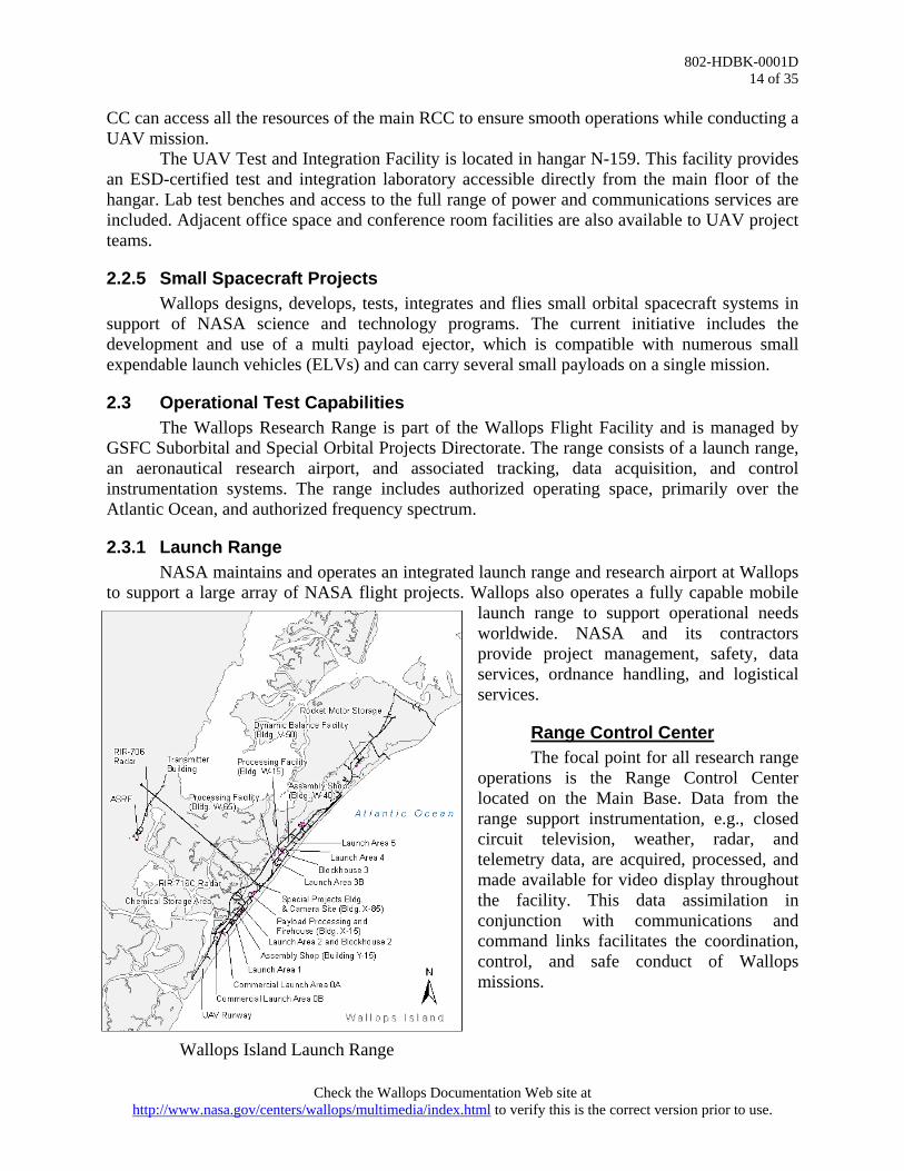
2.3.1 Launch Range NASA maintains and operates an integrated launch range and research airport at Wallops to support a large array of NASA flight projects. Wallops also operates a fully capable mobile
launch range to support operational needs worldwide. NASA and its contractors provide project management, safety, data services, ordnance handling, and logistical services.
Range Control Center The focal point for all research range operations is the Range Control Center located on the Main Base. Data from the range support instrumentation, e.g., closed circuit television, weather, radar, and telemetry data, are acquired, processed, and made available for video display throughout the facility. This data assimilation in conjunction with communications and command links facilitates the coordination, control, and safe conduct of Wallops missions.
Wallops Island Launch Range
Check the Wallops Documentation Web site at http://www.nasa.gov/centers/wallops/multimedia/index.html to verify this is the correct version prior to use.

802-HDBK-0001D 15 of 35
Launch Facilities
The Wallops Island Launch Range is an integrated research range offering fixed and transportable launch facilities. The island site is comprised of five launch pads (some containing multiple launchers); three blockhouses for launch control; and assembly buildings to support the preparation and launch of suborbital and orbital launch systems. User-provided launch systems can be accommodated. A listing of capabilities and characteristics of launchers can be found in 840-HDBK-0001, Wallops Flight Facility Range User’s Handbook.
Instrumentation The Wallops Research Range possesses a highly capable set of range control and data instrumentation systems, including the following:
• Fixed and mobile telemetry systems • Fixed and mobile radar systems • Fixed and mobile UHF transmitter systems • Fixed and mobile command systems • Mobile power vans • Data and voice communication systems • High-speed tracking cameras • Compatibility with downrange federal instrumentation sites
Range instrumentation is operated by the Near Earth Networks Services (NENS) contractor. See the Wallops Flight Facility Range User’s Handbook and 453-GNUG, Ground Network Users’ Guide for more detailed discussion of instrumentation systems.
Processing Facilities The Wallops Research Range has facilities for the receipt, inspection, assembly,
checkout, and storage of rocket motors and other pyrotechnic devices. A multifunctional processing facility is located outside Wallops Main Gate behind the MSC. The facility has two high bays that measure 80 feet x 40 feet x 40 feet high, and other support amenities. Future plans include a Class 100K Clean Room. Refer to the Wallops Flight Facility Range User’s Handbook for descriptions of all assembly and payload processing facilities available at Wallops.
Other facilities available to customers include clean rooms, aircraft hangar space, blockhouses, and furnished office space. Telephone service, fax machines, and LAN access for email and Internet services are available for a fee (see 2.6.9). Wallops operational facilities are linked by fiber optic and telephone cable to allow routing of data from tracking sites to user instrumentation. The drawing below depicts Wallops Mainland and Wallops Island Research Range launch facilities showing location of support facilities and launch pads.
Liquid Fueling Facilities Wallops Research Range can support spacecraft operations using monopropellant
hydrazine. SCAPE1 suits are available for hydrazine fueling operations. The suits are certified
1 Self-Contained Atmospheric Protective Ensemble.
Check the Wallops Documentation Web site at http://www.nasa.gov/centers/wallops/multimedia/index.html to verify this is the correct version prior to use.
802-HDBK-0001D 16 of 35
and come equipped with all hardware, air lines, communications, and portable, hand-held monitors. A cart is available for fuel transfer and contains a catch tank for inline waste product and a scrubber.
The WFF Liquid Fueling Facility (LFF) was conceived as a flexible, expandable, modular, and transportable launch service to accommodate an emerging class of new launch vehicles that utilize liquid fuels as opposed to solid propellants. See the Wallops Flight Facility Range User’s Handbook for a more detailed description of the LFF.
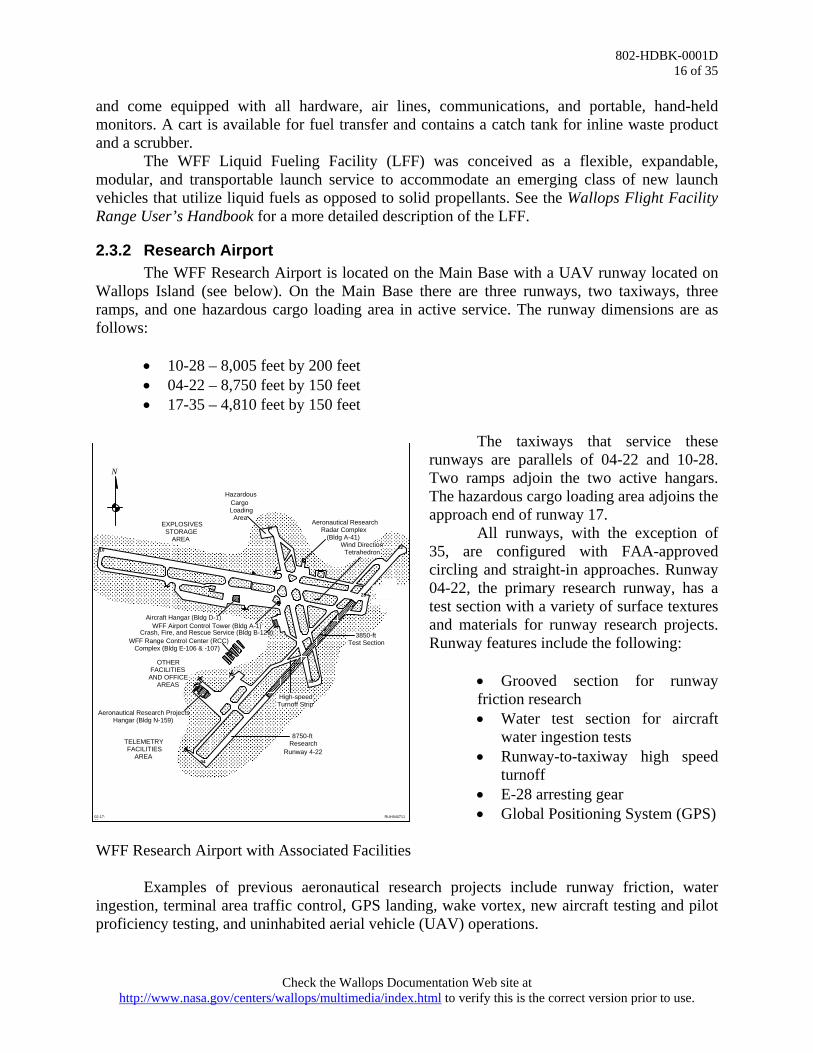
2.3.2 Research Airport The WFF Research Airport is located on the Main Base with a UAV runway located on
Wallops Island (see below). On the Main Base there are three runways, two taxiways, three ramps, and one hazardous cargo loading area in active service. The runway dimensions are as follows:
• 10-28 – 8,005 feet by 200 feet • 04-22 – 8,750 feet by 150 feet • 17-35 – 4,810 feet by 150 feet
The taxiways that service these
runways are parallels of 04-22 and 10-28. Two ramps adjoin the two active hangars. The hazardous cargo loading area adjoins the approach end of runway 17.
10
17
22
28
35
04
N
RUH940711
EXPLOSIVES STORAGE
AREA
Hazardous Cargo Loading
Area Aeronautical Research
Radar Complex (Bldg A-41)
Aircraft Hangar (Bldg D-1) WFF Airport Control Tower (Bldg A-1)
Crash, Fire, and Rescue Service (Bldg B-129) WFF Range Control Center (RCC)
Complex (Bldg E-106 & -107)
Aeronautical Research Projects Hangar (Bldg N-159)
TELEMETRY FACILITIES
AREA
High-speed Turnoff Strip
Wind Direction Tetrahedron
OTHER FACILITIES
AND OFFICE AREAS
3850-ft Test Section
8750-ft Research
Runway 4-22
02-17-95
All runways, with the exception of 35, are configured with FAA-approved circling and straight-in approaches. Runway 04-22, the primary research runway, has a test section with a variety of surface textures and materials for runway research projects. Runway features include the following:
• Grooved section for runway friction research • Water test section for aircraft
water ingestion tests • Runway-to-taxiway high speed
turnoff • E-28 arresting gear • Global Positioning System (GPS)
WFF Research Airport with Associated Facilities Examples of previous aeronautical research projects include runway friction, water ingestion, terminal area traffic control, GPS landing, wake vortex, new aircraft testing and pilot proficiency testing, and uninhabited aerial vehicle (UAV) operations.
Check the Wallops Documentation Web site at http://www.nasa.gov/centers/wallops/multimedia/index.html to verify this is the correct version prior to use.
802-HDBK-0001D 17 of 35
Precision approach path indicators (PAPI) are installed on all runways. C-band radar and control tower support are available. The following support and services can be provided at the Research Airport with prior arrangement:
• Hangar space • Minor and temporary repairs
• Local and national meteorological information
• Fuel services for JP-5 • Flight planning support • Ground power units • First aid and emergency treatment • Aircraft towing • Hazardous cargo handling • Rollaway stairs • Night operations support • Oxygen service, liquid and gaseous • Support for aircraft carrying combat
ordnance
Hangar, office, and shop spaces are available for approved aircraft projects and vary in size and location. Since Wallops is equipped to effect only minor or limited repairs to transient aircraft, project and R&D aircraft should be accompanied by maintenance personnel when engaged in flight operations at Wallops. Limited assistance may be provided for minor repairs. Fuel services are available for U.S. Government program aircraft during normal working hours and at other times by prior arrangement. Fuel is dispensed from trucks equipped with single point refueling fittings. Additional information regarding airport use is in 830-AFOH-0001, Airport Facility and Operations Handbook found at http://wacop.wff.nasa.gov/.
2.3.3 Orbital Tracking The Wallops Orbital Tracking Station (WOTS) provides continuous ground station
receive and transmit capabilities for NASA low-Earth orbiting (LEO) spacecraft. WOTS facilities are flexible and can be used for range telemetry and share resources with the range telemetry systems. WOTS has metric tracking and command uplink.
2.4 Laboratories and Facilities
2.4.1 Fabrication Facilities
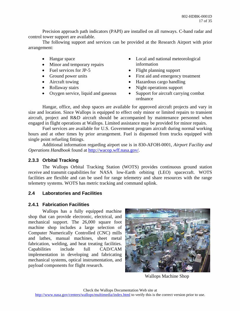
Wallops has a fully equipped machine shop that can provide electronic, electrical, and mechanical support. The 26,000 square foot machine shop includes a large selection of Computer Numerically Controlled (CNC) mills and lathes, manual machines, sheet metal fabrication, welding, and heat treating facilities. Capabilities include full CAD/CAM implementation in developing and fabricating mechanical systems, optical instrumentation, and payload components for flight research. Wallops Machine Shop
Check the Wallops Documentation Web site at http://www.nasa.gov/centers/wallops/multimedia/index.html to verify this is the correct version prior to use.

802-HDBK-0001D 18 of 35
The fabrication area is used for such tasks as sounding rocket launcher refurbishment, and design and fabrication of mobile telemetry and mobile radar support vans and antenna systems. The machine shop includes mechanical technician laboratories for assembly of scientific sounding rocket payloads. While the facility primarily supports the Sounding Rocket Program, it regularly supports other NASA and reimbursable projects. A more comprehensive description of mechanical and electrical fabrication capabilities is available in the Sounding Rocket Program Handbook.
2.4.2 Environmental Test Facilities Environmental testing of complete payloads, subassemblies, and components verifies flight readiness when exposed to an intended flight environment. Environmental testing capabilities available at Wallops can support a full suite of testing requirements from suborbital to small orbital payloads. Specialized facilities for environmental testing are in the Environmental Testing Laboratory in building F-10, adjacent to the Payload Integration Laboratory for convenience in payload handling and logistics. Additional engineering test facilities are available in the Balloon R&D Laboratory and Multiport Payload Processing Center in building F-7. The Magnetic Calibration Facility is in building F-23, and the EMI/RFI chamber is in building F-7. The Dynamic Balance Facility is on Wallops Island in buildings V-45, V-50, and V-55. Various test requirements are briefly described below. A detailed discussion of environmental testing policies and considerations for sounding rockets is included in the Sounding Rocket Program Handbook.
Check the Wallops Documentation Web site at http://www.nasa.gov/centers/wallops/multimedia/index.html to verify this is the correct version prior to use.

802-HDBK-0001D 19 of 35
Spin Deployment Bay (F-10) Can accommodate test articles up to 20 feet in length, 22 inches in diameter, and 1,500 pounds.
Bend Test Apparatus (F-10) Can accommodate test articles up to 21 feet in length and can apply ±5,000-pound test load anywhere along the length of the test article.
Static and Dynamic Balance Machine (F-10) Can accommodate a test article up to 20 feet in length, 22 inches in diameter, and 1,500 pounds.
Vibration Facility (F-10) Wallops has lateral and axial vibration equipment that can accommodate test articles with diameters up to 44 inches, lengths up to 20 feet, and weights up to approximately 2,000 pounds.
Vacuum Chamber (F-10) Chamber is capable of achieving a pressure of 2x10⁻⁵ torr and can accommodate test articles with dimensions up to 7 feet in diameter and 12 feet in length.
Thermal-Vacuum Chambers (F-10) Largest chamber can accommodate test articles with dimensions up to 2 cubic feet. The pressure can be reduced to 3x10⁻⁸ torr at temperatures between –73 and +125 degrees Centigrade.
Mass Properties Apparatus (F-10) This system has a test article weight capacity of 5,000 pounds and a total length capacity of 20 feet.
Centrifuge (F-10) The centrifuge is used for component acceleration tests. It is capable of achieving up to 1000-g acceleration at a radius of 10.5 inches. It has 8 inches of clearance between the 3-foot diameter rotary table and the cover.
Integration Labs (F-10) The integration labs include an array of telemetry receivers, chart recorders, telemetry display terminals, frequency analyzers, and related equipment, and are dedicated to payload electrical testing and functional checks.
Check the Wallops Documentation Web site at http://www.nasa.gov/centers/wallops/multimedia/index.html to verify this is the correct version prior to use.

802-HDBK-0001D 20 of 35
Balloon Research and Development Laboratory (F-7) Membrane material testing includes uniaxial tensile, biaxial cylinder, low temperature, and long-term creep. Currently supports the Ultra-Long Duration Balloon (ULDB).
Thermal-Vacuum Chamber (F-7) Stainless steel chamber with working area of 48 inches by 60 inches. Pressure at vacuum is 10^-8 and can simulate altitude. Hot-cold shroud with 12 circumferential, front door and back end zones controllable to ±2°C within a range of ±100°C. Six ports and data collection system with 32 thermal couples.
Magnetic Calibration Facility (F-23) The facility is capable of canceling the effects of Earth’s gravitational field and then generating a test field in any direction. The facility can accommodate test articles with a total length of 20 feet and a maximum diameter of 10 feet.
EMI/RFI Chamber (F-7) This shielded MIL-STD 461/462 compliant EMI/RFI measurement chamber is used to perform radiated and conducted emission and susceptibility compliance measurements on payloads and vehicle components. MIL-STD 285 shielding is >100 dB up to 40 GHz.
Compact Antenna Range (F-7) This shielded anechoic antenna chamber is used to characterize and analyze vehicle and payload antenna radiation patterns. The compact range reflector simulates far field conditions for aperture sizes up to 6 feet and frequencies up to 100 GHz. MIL-STD 285 shielding is >90 dB up to 40 GHz.
Check the Wallops Documentation Web site at http://www.nasa.gov/centers/wallops/multimedia/index.html to verify this is the correct version prior to use.

802-HDBK-0001D 21 of 35
Dynamic Balance Facility (V-45, V-50, V-55) The facility supports sounding rockets, probes, re-entries, and orbital missions. Building V-45 contains one 10-ton bridge crane with a 23-foot hoist height. Building V-55 houses the Trebel FVD-3000 Aerospace Balancing Machine, which is the largest of its kind in the world. Turntable-workpiece standard adapters are available to fit the 48-inch diameter table. The building contains one 20-ton bridge crane with a 32-foot hoist height. The FVD-3000 is operated remotely from the Blockhouse Control Building, V-50.
Dynamic Balance Facility: Buildings V-45, V-50, and V-55
Three vertical Gisholt balancers are located in building V-45 and are remotely operated and monitored from V-50. The balancers are used primarily for small or medium test setups with restricted diameters. These displacement type machines are the soft bearing amplitude kind. The following table lists the capacities for all balancers.
Trebel FVD-3000 Balancer* Vertical Gisholt Balancers Test specimen weight
50 to 6,000 lb; 35,000 lb maximum at reduced speeds
10 to 300 lb, 40 to 2,000 lb, 50 to 3,300 lb
Balancing velocities 50 to 1,000 rpm 80 to 1,000 rpm Maximum test specimen size
10-ft diameter (15 ft with modifications); maximum height 27 ft
46-inch diameter by 20-ft long A variety of electronic scales are available to measure weight from 0.1 gram to 22,676 kilograms. The Toledo Scale Corporation Portable System determines weight and center of gravity (CG) of the various rocket motor components. The system specifications are below.
Maximum weight capacity: 900 lb Weight accuracy: 0.1% or 1 lb, whichever is greater CG accuracy: ±3 in. over 250 lb, ±2 in. over 500 lb
2.4.3 GPS Simulator Facility The GPS Simulator Facility is comprised of a
4-output Spirent GSS GPS simulator capable of reproducing the RF signal that would be received by a GPS receiver as it travels any trajectory at any time, with parameters such as signal strength, multipathing, antenna patterns controllable for testing of navigation and attitude receivers; a single output Spirent GSS GPS receiver programmable and transportable for use in the field; and a Navigation Laboratories Tapestry GPS/IMU simulator.
GPS Lab
Check the Wallops Documentation Web site at http://www.nasa.gov/centers/wallops/multimedia/index.html to verify this is the correct version prior to use.

802-HDBK-0001D 22 of 35
These simulators may be controlled remotely to produce hardware-in-the-loop, Monte
Carlo simulations of GPS and IMU for satellites and launch vehicle trajectories. No other civilian installation has the capability to develop and test sensors in this manner. Current users include the Sounding Rocket and Scientific Balloon programs and the Autonomous Flight Safety System.
2.4.4 Mission Planning Laboratory (MPL) The Mission Planning Laboratory uses a flexible software tool suite to visualize, analyze and optimize mission specifications based on vehicle characteristics, range setup, and performance to support missions and assess alternatives.
The MPL provides a mathematically correct, visually rich environment that allows realistic simulation, presentation and evaluation of platform selection, flight profiles, and range asset placement. By integrating detailed information on vehicle capabilities, range capabilities, and mission specific objectives, the MPL can meet several critical current needs for the Research Range. MPL has supported orbital missions with trajectory and range asset simulations for the project and with mission visualizations for NASA and the public.
Orbital Launch Simulation
2.4.5 Hydrospheric and Biospheric Sciences Laboratory The Hydrospheric and Biospheric Sciences Laboratory, working within the Earth-Sun
Exploration Division of the Sciences and Exploration Directorate at GSFC, conducts theoretical, experimental and applied research in the oceanic, atmospheric, and terrestrial sciences. Branch personnel design, fabricate and operate both remote and in-situ sensing instruments for aircraft, balloons, and rockets. They plan and conduct laboratory and field measurements to improve the fundamental knowledge of Earth sensing and to evaluate sensor systems as well as quantify and demonstrate system performance. Various instruments and systems available for experiments are discussed briefly below. More detailed discussion is available at http://science.wff.nasa.gov/.
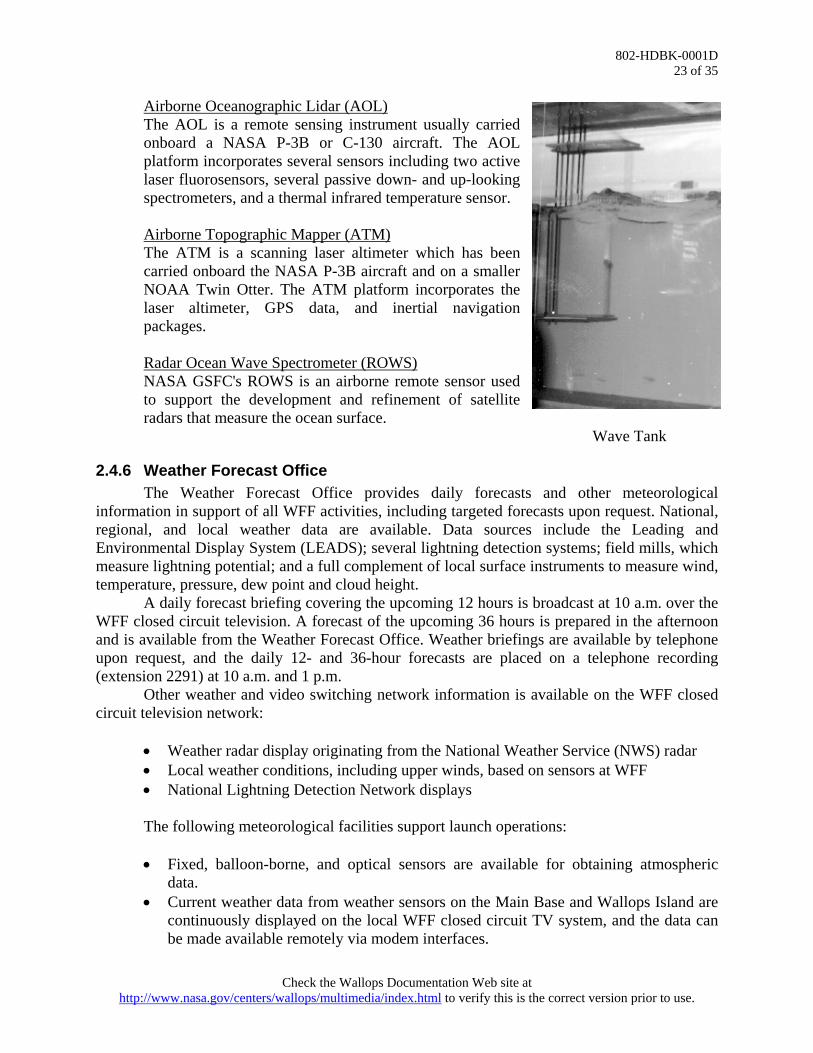
NASA Air-Sea Interaction Research Facility (NASIRF) The primary objectives of NASIRF are to test theoretical results and to collect empirical data for the development of remote sensing techniques, in support of microwave remote sensor development and algorithms for air-sea interaction studies. The photo below depicts part of the 60-foot long wave tank.
Rain-Sea Interaction Facility The goal of the Rain-Sea Interaction Facility is to improve measurements of rain, wind, and air-sea gas exchange over the oceans. Global measurement of these processes contributes to weather prediction and climate modeling.
Check the Wallops Documentation Web site at http://www.nasa.gov/centers/wallops/multimedia/index.html to verify this is the correct version prior to use.
802-HDBK-0001D 23 of 35
Airborne Oceanographic Lidar (AOL) The AOL is a remote sensing instrument usually carried onboard a NASA P-3B or C-130 aircraft. The AOL platform incorporates several sensors including two active laser fluorosensors, several passive down- and up-looking spectrometers, and a thermal infrared temperature sensor.
Airborne Topographic Mapper (ATM) The ATM is a scanning laser altimeter which has been carried onboard the NASA P-3B aircraft and on a smaller NOAA Twin Otter. The ATM platform incorporates the laser altimeter, GPS data, and inertial navigation packages. Radar Ocean Wave Spectrometer (ROWS) NASA GSFC's ROWS is an airborne remote sensor used to support the development and refinement of satellite radars that measure the ocean surface.
Wave Tank
2.4.6 Weather Forecast Office The Weather Forecast Office provides daily forecasts and other meteorological
information in support of all WFF activities, including targeted forecasts upon request. National, regional, and local weather data are available. Data sources include the Leading and Environmental Display System (LEADS); several lightning detection systems; field mills, which measure lightning potential; and a full complement of local surface instruments to measure wind, temperature, pressure, dew point and cloud height.
A daily forecast briefing covering the upcoming 12 hours is broadcast at 10 a.m. over the WFF closed circuit television. A forecast of the upcoming 36 hours is prepared in the afternoon and is available from the Weather Forecast Office. Weather briefings are available by telephone upon request, and the daily 12- and 36-hour forecasts are placed on a telephone recording (extension 2291) at 10 a.m. and 1 p.m.
Other weather and video switching network information is available on the WFF closed circuit television network:
• Weather radar display originating from the National Weather Service (NWS) radar • Local weather conditions, including upper winds, based on sensors at WFF • National Lightning Detection Network displays
The following meteorological facilities support launch operations: • Fixed, balloon-borne, and optical sensors are available for obtaining atmospheric
data. • Current weather data from weather sensors on the Main Base and Wallops Island are
continuously displayed on the local WFF closed circuit TV system, and the data can be made available remotely via modem interfaces.
Check the Wallops Documentation Web site at http://www.nasa.gov/centers/wallops/multimedia/index.html to verify this is the correct version prior to use.

802-HDBK-0001D 24 of 35
• An Ionosphere Sounding Station provides detailed data on the ionosphere
characteristics. • Lightning detection systems display lightning conditions locally and over the United
States. • An Electric Field Measurement System aids in determining the probability of and
detection of local lightning activity. • Indigenous WFF radar data from the Atmospheric Sciences Research Facility (ASRF)
and other Instrumentation Sciences radars are also available in the Weather Office.
2.4.7 Wallops Geophysical Observatory The Wallops Geophysical Observatory (WGO) offers a suite of ground-based science instruments used in support of scientific research. The WGO includes the Atmospheric Sciences Research Facility (ASRF), a magnetometer, digital ionospheric radar station, and high frequency radar, among other instrumentation. The facility possesses unique capabilities for atmospheric data acquisition, processing, display, and recording. Past studies have contributed to the understanding of atmospheric turbulence, cloud and precipitation development and dynamics, lightning discharge characteristics and distribution patterns, as well as the effects of precipitation on the transmission of electromagnetic radiation. Additional information on the WGO can be found in 802-HDBK-0002, Wallops Flight Facility Geophysical Observatory Handbook.
2.4.8 Metrology Laboratory Wallops Flight Facility maintains a Metrology Laboratory equipped to perform repair and calibration of test instruments. Customer-furnished equipment is calibrated and certified at this facility. The equipment in the standards laboratory is traceable to the National Institute of Standards and Testing (NIST). These standards are part of a mandatory recall program for recalibration and certification.
2.4.9 Chemical Laboratory Wallops Flight Facility maintains a chemical laboratory, which performs aviation fuel analysis in support of scientific aircraft and oil analysis in support of radar installations. The lab also performs wastewater analysis for the facility.
2.5 Engineering and Safety Services
2.5.1 Engineering The Mechanical Systems Branch provides mechanical systems mission design and
implementation for suborbital and special orbital projects and for Earth and space science instrument design and development activities at the Wallops Flight Facility. Personnel serve in the Product Design Lead role on key projects and technology development efforts and also provide technical expertise and implementation of integration, testing and launch operations. The Wallops Electrical Engineering Branch is responsible for conception, analysis, design, development, validation, and implementation of electrical/electronic, RF, microwave, and millimeter wave components and systems, which include flight and ground instrumentation, communication, and radar components and systems. The branch supports Wallops ELVs, sounding rockets, aircraft, balloons, satellites, Shuttle payloads, ocean-borne payloads, and support systems.
Check the Wallops Documentation Web site at http://www.nasa.gov/centers/wallops/multimedia/index.html to verify this is the correct version prior to use.

802-HDBK-0001D 25 of 35
The GNC and Mission Systems Engineering Branch provides skills, vision and leadership
in guidance, navigation and control systems, engineering, GNC related operations, and mission analysis. Technical disciplines include flight dynamics, propulsion, flight mechanics, guidance, navigation and control engineering for space systems, experiments, suborbital missions, and launch vehicles. The branch also provides Mission Systems Engineering support for science missions and technology development efforts.
The Wallops Systems Software Engineering Branch (WSSEB) develops integrated systems for real-time mission support; performs prototyping in collaboration with other NASA and government organizations, universities, and commercial partners; and develops test beds/simulators to provide proof of concepts in an operational environment. The WSSEB analyzes, designs, tests, develops, and integrates unique software, hardware, commercial off-the-shelf (COTS), and data systems solutions to meet customer needs.
2.5.2 Safety The Safety Office plans, develops, and provides functional management of policies and
procedures for ground and flight safety, and mission assurance. In addition to its responsibilities for programmatic, operational, and institutional safety, the Safety Office performs engineering analyses of ground and flight safety systems, environmental conditions, and operating activities to assure safety, reliability, and flight worthiness. The Safety Office establishes and approves safety precautions for protection of personal property and the public from hazards generated by ground and flight systems. Safety personnel provide preflight and post-flight analyses for flight missions.
These services are provided for all Wallops-managed projects, both locally and at remote locations. The Safety Office implements the Wallops institutional safety program and manages the base fire department.
A more in-depth discussion of safety policies and procedures can be found in RSM-2002, Range Safety Manual for Goddard Space Flight Center/Wallops Flight Facility.
2.6 Services
2.6.1 Shipping/Receiving Various shipping services are available, including United Parcel Service, Federal Express, and the U.S. Postal Service. The nearest commercial airfreight service is at the Salisbury-Wicomico County Regional Airport, Salisbury, Maryland. The range user should use the following information when mailing correspondence or shipping equipment for official project business:
Mail Address: Name/GSFC Code Number NASA Goddard Space Flight Center Wallops Flight Facility Wallops Island, VA 23337 USA Freight Destination Address: Name/GSFC Code Number C/O Receiving Officer NASA Goddard Space Flight Center
Check the Wallops Documentation Web site at http://www.nasa.gov/centers/wallops/multimedia/index.html to verify this is the correct version prior to use.

802-HDBK-0001D 26 of 35
Wallops Flight Facility Wallops Island, VA 23337 USA
Hazardous materials require special handling. See 2.6.14 below for instructions and references.
2.6.2 NASA Federal Credit Union The NASA Federal Credit Union maintains an office on Wallops Main Base. Personnel employed at GSFC may become members of the credit union. There is an ATM open 24 hours a day. There is also an office off-site on the southeast side of Virginia Rt. 175 and U.S. Rt. 13 intersection. More information on credit union services can be seen at http://www.nasafcu.org.
2.6.3 Cafeteria and Dormitories The Wallops Exchange and Morale Association (WEMA) manages the cafeteria and dormitories. The cafeteria serves breakfast and lunch Monday through Friday, except holidays. Dormitory rooms are rented on a space-available basis. Morale activities can be viewed on base at http://internal.wff.nasa.gov/.
2.6.4 Medical Facilities The Health Unit located on the Main Base is available for limited medical services in the
event of an emergency during working hours. Emergency medical technicians from the fire station are available 24 hours a day. Ambulance services are also available. The Northampton-Accomack Memorial Hospital is approximately 40 miles south in Nassawadox, Virginia. The other local hospital is the Peninsula Regional Medical Center located approximately 40 miles north in Salisbury, Maryland.
2.6.5 Fitness Facility Wallops maintains a fitness facility, which includes a gymnasium, weight room, Nautilus equipment room, locker rooms, and saunas. Guest memberships are available. The Morale Activities Committee (MAC) manages the fitness facility.
2.6.6 Security Wallops Flight Facility maintains 24-hour security for all its property. Personnel without current security badges will not be allowed on the Main Base, the Mainland, or the Island. All visitors must check in with Security at the Main Gate. Foreign nationals must obtain prior approval to visit at least 20 working days in advance of a visit of 30 days or less and 2 calendar months in advance for an assignment over 30 days. More information regarding security requirements can be found in NPR 1620.1, Security Procedures and Guidelines.
2.6.7 Environmental The Wallops Environmental Office is responsible for environmental concerns at Wallops. Services and responsibilities include hazardous waste management; pollution prevention; oil spill prevention and response; storage tank management; air pollution control; water pollution control; historical and archeological preservation; and environmental consulting. Wallops Flight Facility
Check the Wallops Documentation Web site at http://www.nasa.gov/centers/wallops/multimedia/index.html to verify this is the correct version prior to use.
802-HDBK-0001D 27 of 35
has an existing site-wide environmental assessment that envelops most activities conducted here. In most cases, an additional assessment is not necessary.
2.6.8 Fire Department There are two fire stations at Wallops, one on the Main Base and one on Wallops Island. Both stations are manned 24 hours a day by fully trained firefighters and emergency medical technicians. Each station is equipped to meet Wallops emergency response requirements.
2.6.9 Communications Telephone service is provided through the Federal Telecommunications System (FTS-2000) for official U.S. Government business. Long-distance billing can be supported by telephone credit cards or prorated FTS accounts for non-Government projects. Fax service is available. Modem support for range user computers may be provided through the digital PBX system. Teleconferencing and video teleconferencing services are available through the customer’s sponsor. Portable audio conferencing equipment is also available. There are no restrictions on pagers and cell phones. The Outsourcing Desktop Initiative for NASA (ODIN) contractor can provide Internet access in three ways: via ODIN, the Guest Network (limited access), and non-ODIN connection (full access). ODIN can be used for long- or short-term access with associated cost. The Guest Network can be used for short-term access via sponsor request with no cost. Non-ODIN full access would require going through the entire computer security process with the sponsor vouching for any individual using full access resources. Several buildings on the Main Base have wireless network coverage.
2.6.10 Library NASA maintains a scientific and technical library in Building E-105, Main Base. Local and national newspapers and periodicals are available on site, as well as computers with access to the Internet. The library is open from 8:00 a.m. to 4:30 p.m. Monday through Friday.
2.6.11 Print Shop The Print Shop features a variety of duplicating equipment that produces a wide range of products from door signs to Braille documents. The state-of-the-art high-speed duplicator produces copies quickly and with special features such as storing documents for reprints and simultaneous mail merging. Customers can transmit their documents electronically rather than providing a "camera ready" hard copy. Moreover, there is a wide range of binding options for documents. Not all services are available at Wallops, but the Print Shop can arrange to have those services performed at the Greenbelt location.
2.6.12 Photo Services Photo Services supports technical, scientific, and administrative organizations at Wallops. The Digital Imaging Facility complements the traditional photographic services and provides many new capabilities in-house. Photo Services also offers a videotaping capability, including video production and tape duplication, as well as distribution and life cycle management of finished programs. The Photographic Services Team provides many more services and areas of support, such as photographic stills and high-speed video tracking.
Check the Wallops Documentation Web site at http://www.nasa.gov/centers/wallops/multimedia/index.html to verify this is the correct version prior to use.

802-HDBK-0001D 28 of 35
2.6.13 Material Handling Equipment A variety of material handling equipment is available at Wallops, including forklifts, overhead hoists, cranes, basket trucks, and material moving equipment. Additional information on types of material handling equipment can be found in the Wallops Flight Facility Range User’s Handbook.
2.6.14 Warehousing and Hazardous Materials Storage Warehouse space is available on a limited basis. The customer should notify the Wallops point of contact in advance of the type and amount of storage required, including chemical, explosive, and inert hardware storage. All hazardous material must be packaged to conform to applicable Department of Transportation regulations. A Material Safety Data Sheet (MSDS) must accompany all hazardous materials shipped to Wallops. For more information regarding hazardous materials shipment and storage, see the Sounding Rocket Program Handbook, the Wallops Flight Facility Range User’s Handbook, and GPG 1860.1, Ionizing Radiation Protection, which defines procedures and provides the needed forms.
Check the Wallops Documentation Web site at http://www.nasa.gov/centers/wallops/multimedia/index.html to verify this is the correct version prior to use.

802-HDBK-0001D 29 of 35
Part III: Policies and Procedures 3.1 Initial Contact Process The Advanced Projects Office (APO) is the primary resource for initial contact with Wallops Flight Facility. The APO serves as the focal point for external organizations desiring to conduct business with WFF. The APO can address most preliminary questions and can organize any further discussions or meetings. Once a project becomes accepted, the APO hands off to a designated point-of-contact (POC) or Project Manager, who then becomes the customer interface for the duration of the project. The APO continues to serve as a customer advocate and is available should the customer have issues concerning WFF support. The APO can be reached from the WFF Web page or from the address and phone number listed below. If you have an established contact at Wallops, that person can direct you to the appropriate organization to meet your needs.
3.2 Policy on Support to Non-NASA Customers While NASA's primary mission at WFF is the support of NASA science and technology programs, Wallops personnel and facilities can, and do, support other government agencies, commercial industry, or educational institutions on a cost reimbursable basis. Non-NASA support is a substantial portion of the WFF workload and is accepted on a non-interference basis with core NASA projects. The only major restriction is that WFF cannot compete with private industry for support on commercial projects.
3.3 Options for Conducting Work at WFF There are several ways a customer may conduct activities at WFF. These options include:
• Direct agreement with NASA/WFF • Agreement through the Mid-Atlantic Regional Spaceport (Virginia Commercial
Space Flight Authority) or the U.S. Navy tenants • Agreement through WFF contractors
A direct agreement is the most frequent path for arranging NASA/WFF support. The process for establishing an agreement is described below. Often an organization may have reason to establish a relationship with a WFF tenant organization such as the MARS or U.S. Navy. WFF can indirectly support this organization through an agreement with the tenant organization. Under these circumstances, NASA is officially supporting the tenant. The cost to the customer for NASA support should generally be the same as through a direct relationship. For Commercial Space Launch Act (CSLA) projects, there may be advantages to contracting with the MARS for its services, as well as those provided by NASA. MARS has established CSLA agreements with NASA. This relationship allows NASA and MARS to quickly establish a project-specific Individual Support Annex (ISA), and eliminates the requirement to establish an Agreement and Subagreement as discussed below. MARS also offers additional services and business incentives not available through NASA.
Check the Wallops Documentation Web site at http://www.nasa.gov/centers/wallops/multimedia/index.html to verify this is the correct version prior to use.
802-HDBK-0001D 30 of 35
NASA/WFF also encourages resident contractors to develop new business for WFF. Contractors may either refer potential customers to NASA, or may contract directly with the customer to supply services that may include those provided by the contractor and/or NASA. Under these circumstances, the contractor would establish an agreement with NASA to supply services.
3.4 Acceptance Processes The process for accepting new projects depends on the nature of the customer and the project proposed. The process generally starts with a letter of request to WFF. The letter should be sent to
Director of Suborbital and Special Orbital Projects Directorate NASA/GSFC/Wallops Flight Facility Wallops Island, VA 23337
For NASA or other U. S. Government organizations requesting a well-defined, relatively short-term task, WFF will respond with an acceptance letter, establishing the WFF POC, a cost estimate, and any terms of acceptance. For more complex or ongoing activities, a Memorandum of Agreement may be more appropriate, providing more explicit details of the agreement. For commercial or educational organizations, a Space Act Agreement is the appropriate process. A Space Act Agreement is similar to a Memorandum of Agreement but contains additional language addressing legal concerns such as liability. NASA can agree to support commercial launch service providers through a series of CSLA documents. The first is an Agreement established with NASA Headquarters. This is followed by a Subagreement with the Goddard Space Flight Center. Once these general agreements are in place, project-specific ISAs can be established with WFF. The multi-tiered agreements are required because the CSLA requires federal agencies to set aside some expenses that would otherwise be passed along to the customer. The APO or the designated POC will assist in establishing any necessary agreements.
3.5 Single Point-of-Contact Concept NASA/WFF operates on a single point-of-contact (POC) concept. Once WFF accepts a request for support, a POC is assigned, normally a Project Manager. While customer activities may involve support from numerous Wallops organizations, the POC will serve to assure that there is a single person to coordinate all customer services. This includes administrative, technical, and operational support. While WFF encourages the establishment of close working relationships between customers and WFF supporting organizations, customers will always have a focal point for their business.
3.6 Financial Processes As a federal organization, NASA/WFF financial processes must comply with federal law. The following policies apply to our financial practices:
• For NASA customers, some expenses may be covered by NASA funding and may not
be passed on to customers.
Check the Wallops Documentation Web site at http://www.nasa.gov/centers/wallops/multimedia/index.html to verify this is the correct version prior to use.

802-HDBK-0001D 31 of 35
• WFF cannot make a profit. WFF can only recapture actual expenses in supporting a
customer. • According to federal law, NASA must recoup actual expenses, regardless of any cost
estimate provided. • NASA cannot support projects without adequate funding in place. WFF cannot begin
work until funding is established, and cannot continue work if available funding has been expended.
• For commercial projects, NASA cannot compete with commercial entities offering similar services.
• For projects accepted according to the Commercial Space Launch Act, certain NASA expenses cannot be passed along to customers.
The APO will provide a cost estimate for any prospective activity. The quality of the estimate will be dependent on WFF experience with similar activities and the level of detailed assumptions provided by the customer. NASA accepts a number of funding mechanisms, depending on the customer type. For NASA projects, a budget guideline change to reallocate funding to GSFC is the normal approach. For DoD organizations, a Military Interdepartmental Purchase Request (MIPR) can be provided. For commercial activities a corporate cashier’s check can be used. All funding should be provided to
Office of the Chief Financial Officer Goddard Space Flight Center Greenbelt, MD 20771
For extended projects, the POC can provide periodic financial status reports. Upon completion of a project, a final accounting of expenses will be compiled. The customer will receive a letter from the Comptrollers Office detailing final expenses and providing a refund for leftover funds, or requesting additional payment for any shortfall. The POC will address any financial issues the customer may have.
3.7 Safety Processes NASA has ultimate safety authority for all activities conducted at WFF. WFF, however, also strives to provide a customer-friendly safety program while carrying out its responsibilities. Safety Office personnel must review and approve all projects prior to their initiation. For flight projects this typically involves review of mission plans, vehicle and payload design, and operational procedures. WFF safety requirements are defined in RSM-2002, Range Safety Manual for Goddard Space Flight Center/Wallops Flight Facility, available from key WFF personnel or on the WFF Web site. The Safety Office works with customers to define documentation requirements and to establish operational plans that assure that safety requirements are satisfied while minimizing the burden to the project. For projects previously conducted at other sites or otherwise subjected to safety review, WFF Safety Office personnel will take advantage of previous safety analyses, minimizing cost and impact to the project. It is a WFF practice to involve safety personnel early in a project’s life in order to identify any potential problems that can be resolved without impacting schedule or cost.
Check the Wallops Documentation Web site at http://www.nasa.gov/centers/wallops/multimedia/index.html to verify this is the correct version prior to use.
802-HDBK-0001D 32 of 35
3.8 Environmental Processes NASA/WFF has a number of existing environmental documents in place that address the impacts of its various flight projects and operations. In most cases WFF environmental documentation adequately addresses additional projects from new customers. Early in a new project, WFF will evaluate whether the existing WFF assessments adequately address the environmental concerns of a customer’s project. Should a planned activity be outside the scope of our documentation, our environmental staff will work with the customer to define a plan of action. The customer’s POC will coordinate dealings with the Wallops Environmental Office.
3.9 Frequency Utilization Because WFF has a large number of instrumentation systems that radiate or receive radio frequency (RF) signals, frequency interference is a significant concern. WFF also regularly performs activities with ordnance systems that are susceptible to RF energy. To protect against frequency conflicts, the WFF Frequency Coordinator must approve all transmitting systems utilized at WFF. The customer’s POC will coordinate frequency approvals. See 800-HDBK-0001, Wallops Flight Facility Frequency Utilization Management Handbook for more information and forms.
3.10 ISO 9001 In November 1999, NASA/WFF became ISO 9001 certified. All flight projects, mission operations, and other major services have established practices designed to provide high quality, customer oriented support.
3.11 Customer Feedback We constantly strive to provide the highest caliber of service to our customers. In order to identify areas of improvement, WFF would like feedback from you. You may be requested to evaluate our performance by your WFF point of contact. If not, you may provide any comments to
Advanced Projects Office NASA/GSFC Wallops Island, VA 23337 (757) 824-1275 [email protected]
Your thoughts on WFF support are important and assure that WFF continues to provide quality service.
Check the Wallops Documentation Web site at http://www.nasa.gov/centers/wallops/multimedia/index.html to verify this is the correct version prior to use.

802-HDBK-0001D 33 of 35
Appendix A
Abbreviations and Acronyms
AFOH Airport Facility and Operations Handbook AOL Airborne Oceanographic Lidar APO Advanced Projects Office ASRF Atmospheric Sciences Research Facility ATM Airborne Topographic Mapper; automatic teller machine AWIPS Advanced Weather Interactive Processing System CAD Computer-aided Design CAM Computer-aided Manufacture CC Control Center CNC Computer Numerically Controlled C/O Care of COTS Commercial Off-the-Shelf CSBF Columbia Scientific Balloon Facility CSLA Commercial Space Launch Act DoD Department of Defense EDARS Environmental Data Acquisition and Recording System ELC Emerging Launch Company ELV Expendable Launch Vehicle EMI Electromagnetic Interference ESD Electrostatic Discharge ft Foot; feet FTS Federal Telecommunication System GNC Guidance, Navigation and Control GNUG Ground Networks Users’ Guide GPG Goddard Procedures and Guidelines GPS Global Positioning System GSFC Goddard Space Flight Center HB Handbook HDBK Handbook IMU Inertial Measurement Unit in. Inch; inches ISA Individual Support Annex ISO International Organization for Standardization LAN Local Area Network lb Pound; pounds LFF Liquid Fueling Facility MAC Morale Activities Committee MD Maryland MIPR Military Interdepartmental Purchase Request MPL Mission Planning Laboratory MSC Marine Science Consortium MSDS Material Safety Data Sheet NACA National Advisory Committee for Aeronautics NASA National Aeronautics and Space Administration
Check the Wallops Documentation Web site at http://www.nasa.gov/centers/wallops/multimedia/index.html to verify this is the correct version prior to use.

802-HDBK-0001D 34 of 35
NASIRF NASA Air-Sea Interaction Research Facility NAWCAD Naval Air Warfare Center NENS Near Earth Networks Services NESDIS National Environmental Satellite, Data, and Information Service NFCU NASA Federal Credit Union NIST National Institute of Standards and Testing NOAA National Oceanic and Atmospheric Administration NPR NASA Procedural Requirement NSROC NASA Sounding Rocket Operations Contract NWS National Weather Service ODIN Outsourcing Desktop Initiative for NASA PAPI Precision Approach Path Indicator PBX Private Branch Exchange POC Point of Contact R&D Research and Development RCC Range Control Center RF Radio Frequency RFI Radio Frequency Interference ROWS Radar Ocean Wave Spectrometer rpm Revolutions per minute RSM Range Safety Manual SBFF Scientific Balloon Flight Facility SCAPE Self-contained Atmospheric Protective Ensemble SCSC Surface Combat Systems Center SEM Space Experiment Module SRP Sounding Rocket Program STS Space Transportation System TOTS Transportable Orbital Tracking Station TV Television U.S. United States UAV Uninhabited Aerial Vehicle UHF Ultra-high Frequency ULDB Ultra-Long Duration Balloon USA United States of America USCG United States Coast Guard USN United States Navy VA Virginia VCSFA Virginia Commercial Space Flight Authority VSFC Virginia Space Flight Center WEMA Wallops Employee and Morale Association WFF Wallops Flight Facility WGO Wallops Geophysical Observatory WOTS Wallops Orbital Tracking System WSSEB Wallops Systems Software Engineering Branch
Check the Wallops Documentation Web site at http://www.nasa.gov/centers/wallops/multimedia/index.html to verify this is the correct version prior to use.
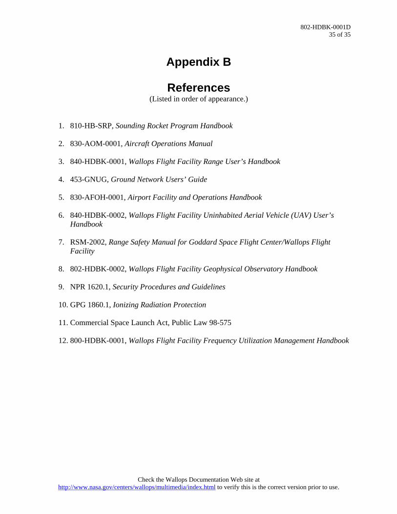
802-HDBK-0001D 35 of 35
Appendix B
References (Listed in order of appearance.)
1. 810-HB-SRP, Sounding Rocket Program Handbook
2. 830-AOM-0001, Aircraft Operations Manual
3. 840-HDBK-0001, Wallops Flight Facility Range User’s Handbook
4. 453-GNUG, Ground Network Users’ Guide
5. 830-AFOH-0001, Airport Facility and Operations Handbook
6. 840-HDBK-0002, Wallops Flight Facility Uninhabited Aerial Vehicle (UAV) User’s Handbook
7. RSM-2002, Range Safety Manual for Goddard Space Flight Center/Wallops Flight
Facility
8. 802-HDBK-0002, Wallops Flight Facility Geophysical Observatory Handbook
9. NPR 1620.1, Security Procedures and Guidelines
10. GPG 1860.1, Ionizing Radiation Protection
11. Commercial Space Launch Act, Public Law 98-575
12. 800-HDBK-0001, Wallops Flight Facility Frequency Utilization Management Handbook
Check the Wallops Documentation Web site at http://www.nasa.gov/centers/wallops/multimedia/index.html to verify this is the correct version prior to use.