SUBMERSIBLE PUMP CONTROLLER - Depco Pump … PUMP CONTROLLER. ... the controller or in the manual,...
40
Balanced Flow ® SUBMERSIBLE PUMP CONTROLLER INSTALLATION, OPERATION AND MAINTENANCE INSTRUCTIONS INSTRUCTION MANUAL IM182
Transcript of SUBMERSIBLE PUMP CONTROLLER - Depco Pump … PUMP CONTROLLER. ... the controller or in the manual,...

Balanced Flow®
SUBMERSIBLE PUMP CONTROLLERINSTALLATION, OPERATION AND MAINTENANCE INSTRUCTIONS
INSTRUCTION MANUALIM182

2
Owner’s Information
Controller Model Number:
Controller Serial Number:
Pump Model Number:
Pump Serial Number:
Motor Model Number:
Motor SFA:
Tank Serial Number:
Dealer:
Dealer Telephone Number:
Installation Date:
Wire Lengths (Feet) Service Entrance to Controller: Controller to Well: Top of Well to Motor:
Incoming Voltage:
Owner’s Information Table of Contents
SUBJECT PAGE1. Safety Instructions ..................................................... 3 Typical Installation ..................................................... 3 Ratings ...................................................................... 4 Required Materials .................................................... 42. Installation ................................................................ 4 Controller .................................................................. 4 Pump and Piping ........................................................ 4 Splicing Drop Cable to Motor Leads .......................... 4 Wiring Pressure Transducer ........................................ 5 Motor Wires .............................................................. 5 Input Power ............................................................... 5 User Interface Board .................................................. 83. Installer Pre-Start Selections ...................................... 6 Maximum Frequency (Speed) Switch ......................... 6 Dry Well Sensitivity ................................................... 6 Broken Pipe Protection .............................................. 6 Pressure Drop ............................................................ 6 Motor Overload Setting Dial ..................................... 6 Pressure Adjustment Pushbuttons ............................... 6 Controller Status Indicator ........................................ 6 Purging System .......................................................... 6 Checking Rotation ..................................................... 6 Checking for Leaks .................................................... 7 Switch Input .............................................................. 7 Table 4: Wire Sizing ................................................... 94. Troubleshooting ................................................. 10-12Limited Warranty ........................................................ 12
Table of Contents
PLEASE USE THIS CONTROLLER INSTALLATION, OPERATION AND TROUBLESHOOTING MANUAL (IOM) IN CONJUNCTION WITH THE PUMP IOM. THE CONTROLLER IOM COVERS THE CONTROLLER ELECTRICAL INSTALLATION AND ANY SPECIAL INSTALLATION PROCEDURES REQUIRED WITH VARIABLE SPEED CONTROLLERS.
GOULDS WATER TECHNOLOGY WILL NOT BE RESPONSIBLE FOR ANY DAMAGES TO AN INSTALLATION WHERE THE PRESSURE RELIEF VALVE IS ALLOWED TO DISCHARGE INTO A FINISHED LIVING SPACE OR TO OTHERWISE DAMAGE A CUSTOMERS PROPERTY. PLUMBING SAFETY DEVICES SUCH AS PRESSURE RELIEF VALVES TO AN APPROPRIATE DRAIN IS THE RESPONSIBILITY OF THE INSTALLER AND IS OUT OF OUR CONTROL.
Water Ends and CentriPro Motors include these extra data labels. Please attach them to the inside cover of the Balanced Flow Controller for future pump and motor identification.
NOTICE: RECORD THE MODEL NUMBERS AND SERIAL NUMBERS FROM THE PUMP AND CONTROLLER IN THIS INSTRUCTION MANUAL FOR FUTURE REFERENCE. GIVE IT TO THE OWNER OR AFFIX IT TO THE CONTROLLER WHEN FINISHED WITH THE INSTALLATION.
Submersible Pump33GS15
CentriPro®
Motor: M30432/300C3133.00 HPFLA: 9.2 SFA: 10.1 LRA: 59SF: 1.15 Hz: 60Volts: 230 PH: 3

3
1: SAFETY INSTRUCTIONS TO AVOID SERIOUS OR FATAL PERSONAL INJURY OR MAJOR PROPERTY DAMAGE, READ AND FOLLOW ALL SAFETY INSTRUCTIONS IN MANUAL AND ON EQUIPMENT.
THIS MANUAL IS INTENDED TO ASSIST IN THE INSTALLATION AND OPERATION OF THIS UNIT AND MUST BE KEPT WITH THE UNIT.
This is a SAFETY ALERT SYMBOL. When you see this symbol on the pump, the controller or in the manual, look for one of the following signal words and be alert to the potential for personal injury or property damage.Warns of hazards that WILL cause serious personal injury, death or major property damage.Warns of hazards that CAN cause serious personal injury, death or major property damage.Warns of hazards that CAN cause personal injury or property damage.
NOTICE: INDICATES SPECIAL INSTRUCTIONS WHICH ARE VERY IMPORTANT AND MUST BE FOLLOWED.THOROUGHLY REVIEW ALL INSTRUCTIONS AND WARNINGS PRIOR TO PERFORMING ANY WORK ON THIS CONTROLLER.MAINTAIN ALL SAFETY DECALS.
DANGER
WARNING
CAUTION
This controller is not designed for use around swimming pools, open bodies of
water, hazardous liquids, or where flammable gases exist.Do not use GFCI input power. This will cause nuisance faults.Disconnect and lockout electrical power before installing or servicing any electrical equipment.
ELECTROCUTION HAZARD. CONTROLLER INPUT GROUND
TERMINAL (GND) AND ALL EXPOSED METAL PIPING, INCLUDING PRESSURE TRANSDUCER CASE, MUST BE CONNECTED TO THE SERVICE ENTRANCE GROUND TERMINAL.
All electrical work must be performed by a qualified technician. Always follow
the National Electrical Code (NEC), or the Canadian Electrical Code, as well as all local, state and provincial codes. Code questions should be directed to your local electrical inspector. Failure to follow electrical codes and OSHA safety standards may result in personal injury or equipment damage. Failure to follow manufacturer’s installation instructions may result in electrical shock, fire hazard, personal injury or death, damaged equipment, unsatisfactory performance, and may void manufacturer’s warranty.
NOTICE: Some installations pull a vacuum on the transducer when the system is drained. The new controller is designed to protect against up to 17” Hg. of vacuum on the transducer. An optional Gauge Guard, order no. 6K210, will protect the transducer from a vacuum condition.
WARNING
PARTS DESCRIPTION:
1) Pump and Motor 10) Power Supply Cable2) Check Valve (built-in 11) Service Entrance on some models) 12) Pressure Sensor Cable3) Torque Arrestor (optional) with drip loop 4) Pump Power Cable 13) Diaphragm Tank with Splice Kit 14) Pressure Transducer 5) Electrical Tape 15) Pressure Gauge (Cable to Pipe) 16) Relief Valve 6) Safety Rope (optional) 17) Shut-Off Valve7) Well Cap / Seal 18) Drop Pipe8) Pitless Adapter 19) Lateral Pipe9) Controller 20) Electrical Disconnect
17
16
9
15
11
10
12
13
14
48
7
6
5
4
3
2
1
TYPICAL INSTALLATIONTYPICAL INSTALLATION
18
19
20
WARNING
WARNING
WARNING
1: SAFETY INSTRUCTIONS
WARNING
4
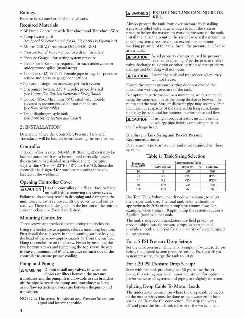
RatingsRefer to serial number label on enclosure.
Required Materials•BFPumpControllerwithTransducerandTransducer Wire•Pump(waterend) (see Speed Selector Switch for 60 Hz or 80 Hz Operation)•Motor:230V,threephase(3Ø),3450RPM•PressureReliefValve–pipedtoadrainforsafety•PressureGauge–forsettingsystempressure•HeatShrinkKit–onerequiredforeachunderwateror
underground splice (mandatory)•TankTeeor(2)¼"NPTFemalepipefittingsforpressure
sensor and pressure gauge connections•Pipeandfittings–asnecessarypereachsystem•DisconnectSwitch:230V,2pole,properlysized
(see Controller, Breaker, Generator Sizing Table)•CopperWire:Minimum75ºCratedwire,double
jacketed is recommended but not mandatory (see Wire Sizing table)
•Tank:diaphragmstyletank (see Tank Sizing Section and Chart)
2: INSTALLATIONDetermine where the Controller, Pressure Tank and Transducer will be located before starting the installation.
ControllerThe controller is rated NEMA 3R (Raintight) so it may be located outdoors. It must be mounted vertically. Locate the enclosure in a shaded area where the temperature stayswithin0ºFto+122ºF(-18ºCto+50ºC).Sincethecontroller is designed for outdoor mounting it may be located at the wellhead.
Opening Controller CoverLay the controller on a flat surface or hang on wall before removing the cover screw.
Failure to do so may result in dropping and damaging the unit. Once screw is removed, lift the cover up and out to remove. There is a locking tab on the bottom of the unit to accommodate a padlock if so desired.
Mounting ControllerThree screws are provided for mounting the enclosure. Using the enclosure as a guide, select a mounting location. First install the top screw in the mounting surface leaving the head of the screw approximately 1⁄8"fromthesurface.Hang the enclosure on this screw. Finish by installing the two bottom screws and tightening the top screw. Be sure to leave a minimum of 6" of clearance on each side of the controller to ensure proper cooling.
Pump and PipingDo not install any valves, flow control devices or filters between the pressure
transducer and the pump. It is allowable to run branches off the pipe between the pump and transducer as long as no flow restricting devices are between the pump and transducer.
NOTICE: The terms Transducer and Pressure Sensor are equal and interchangeable.
2: INSTALLATION
EXPLODING TANK CAN INJURE OR KILL.
Always protect the tank from over pressure by installing a pressure relief valve large enough to limit the system pressure below the maximum working pressure of the tank. Install the tank at a point in the system where the maximum possible system pressure cannot exceed the maximum working pressure of the tank. Install the pressure relief valve at the tank.
Avoid property damage caused by pressure relief valve opening. Pipe the pressure relief
valve discharge to a drain or other location so that property damage and flooding will not occur.
Locate the tank and transducer where they will not freeze.
Ensure the system pressure setting does not exceed the maximum working pressure of the tank.For optimum performance, as a minimum, we recommend using the same size pipe as the pump discharge between the pump and the tank. Smaller diameter pipe may severely limit the maximum capacity of the system. On long runs, larger pipe may be beneficial for optimum performance and flow.
If using a torque arrestor, install it on the discharge pipe before connecting pipe to
the discharge head.
Diaphragm Tank Sizing and Pre-Set Pressure Recommendations:Diaphragm type (captive air) tanks are required on these systems.
Table 1: Tank Sizing Selection Maximum Recommended Tanks Pump GPM Total Volume Order No. or Order No. 10 2 V6P TP6P 23 4.5 V15P TP15P 41 8.2 V25P TP25P 70 13.9 V45 TP45 100 19.9 V60 TP60
Use Total Tank Volume, not drawdown volume, to select the proper tank size. The total tank volume should be approximately 20% of the pump’s maximum flow. For example, when using a 10 gpm pump the system requires a 2 gallon (total volume) tank.The tank sizing recommendations are field proven to prevent objectionable pressure drops on start-up and provide smooth operation for the majority of variable speed pump systems.
For a 5 PSI Pressure Drop Set-up:Set the tank pressure, while tank is empty of water, to 20 psi below the desired system pressure setting. Ex. for a 50 psi system pressure, charge the tank to 30 psi.
For a 20 PSI Pressure Drop Set-up:Start with the tank pre-charge set 30 psi below the set point, this setting may need minor adjustment for optimum performance as all systems and piping are slightly different.
Splicing Drop Cable To Motor LeadsThe underwater connection where the drop cable connects to the motor wires must be done using a waterproof heat shrink kit. To make the connection, first strip the wires ½"andplacetheheatshrinktubesoverthewires.Then,
WARNING
CAUTION
CAUTION
CAUTION
WARNING
CAUTION

5
CAUTION
connect the wires using the crimps. Finish by shrinking the tubes over the crimps heating from the center outward. The sealant in the tube will flow out the ends making a watertight seal. If a heat shrink tube is burnt or split, the connection will need to be remade.
Vinyl electrical tape is not acceptable for underwater splices when using variable
speed drives due to the high potential for leakage to ground through taped joints. Failure to use a waterproof heat shrink kit will void the warranty.Before installing the motor in the well, the drop cable must be connected to the motor wires. Refer to the wire size chart when selecting wire size for the drop cable. See Wire Sizing Table.
Wiring Pressure TransducerTransducer wires must never be in same conduit with power wires. There should
alwaysbeaminimumof12"betweentransducerwiresand power wires. Failure to separate these wires can cause controller malfunctions.The pressure transducer cable is pre-wired at the factory. If desired, the length of the cable can be changed. The cable can also be put in conduit to protect against damage.
To change the length of the transducer cable:•Cablelengthcannotexceed200'.•Disconnecttransducerwiresfromterminalblockbypushing
down on tabs at rear of block one at a time and pulling the wires out of the terminal.
•Spliceadditionalcabletotransducerwire,cutoffexcessasrequired.
•Reconnectwirestoterminalblock.Besurewirecolorsmatchlabels on circuit board (B = Black, R = Red, W = White).
To put the transducer cable in conduit, do the following: Disconnect the cable from the terminal block and remove the cable strain relief in the bottom of the enclosure. Startingattheenclosure,runflexibleorrigid½"conduittowhere the transducer is located. The last few feet of conduit adjacent to the transducer will need to be flexible. The conduitmustbewellsupported–NOstresscanbeplacedon the pressure transducer connector. Use a strain relief bushing to seal around the pressure transducer connector.
After reconnecting the transducer wires to the terminal block and ground terminal, tug
on each wire individually to ensure they are tight.
Any exposed metal in the system piping, including transducer case, must be grounded
to the service entrance per NFPA 70: National Electrical Code, Article 250.
The transducer cable has a Green ground wire and a ground clamp supplied to facilitate grounding the transducer. See Figure 1.
Motor Wires – See Table 4NOTE: A MINIMUM OF 75ºC COPPER WIRE IS MANDATORY.Refer to the Table 4 for wire sizing and maximum wire lengths. Charts are designed to limit voltage drop to 5%.
Size wire for worst case scenarios (low voltage) and stay within the charts recommendations. Insure that the wire is rated for direct burial and/or submergence.
Figure 1: Transducer Grounding
Figure 2 shows the terminal block where the motor and input wires connect. The protective cover on the terminal block snaps off and on. Attach the motor wires to the terminals according to colors marked on circuit board: GND = Green, RED = Red, BLK = Black, YEL = Yellow. Reversing any two leads on RED/BLK/YEL will change the direction of motor rotation. Later during start-up you may need to change motor rotation.
Input PowerSHOCK OR ELECTROCUTION HAZARD
Connect a ground wire from the service panel to the terminal marked GND. Controller has high leakage to ground. Controller ground terminal must be connected to the service entrance ground terminal. Failure to do so will result in high voltage being present on the controller chassis. Connect two “hot” wires from the 2 pole circuit breaker to the terminals marked L1 and L2.
The input power system used must be a grounded power system. The voltage measured from L1 to L2 must be in the range of 196Vac to 265Vac. The voltage measured from L1 to GND must be equal to the voltage measured from L2 to GND. These voltages must be within the range of 120Vac+/-10%.Reduced input voltage will reduce system performance.
Do not use a Ground Fault Circuit Interruptor (GFCI) with this product or nuisance tripping will result.
Figure 2: Wiring Connections
NOTE: IT MAY BE NECESSARY TO PLACE A DISCON-NECT SWITCH IN FRONT OF AND WITHIN SIGHT OF THE CONTROLLER – CONSULT LOCAL CODES.
CAUTION
CAUTION
WARNING
CAUTION
Incoming Power Wires to Motor

6
3: INSTALLER PRE-START SELECTIONS
DRIVE SETTINGS AND PROTECTIONMaximum Frequency (Speed) Switch The Maximum Frequency switch sets the maximum frequency (motor speed) the controller uses to energize the motor to either 60 or 80 Hz. •60Hz-Useformatchedpump-motorcombinations
where the motor HP and pump HP are the same. Example: 2 HP WE and 2 HP Motor
•80Hz-Useformis-matchedpump-motorcombinationswhere motor HP is larger than the pump HP (typically 2x larger). Example: 1 HP WE and 2 HP Motor
•Theunitisfactorypre-setat60Hz.
Dry Well SensitivitySelections are High or Low. This function protects the system from running dry. The selection depends on several conditions and pump size.Start with the sensitivity on high and test by running pump at various flows. If a dry well fault is triggered, switch to low setting. The unit is factory pre-set at high.Restart times in minutes are: 1, 10, 20, 30, 60, 60 and repeating every 60 minutes thereafter. Example: 1st fault shuts down for 1 minute, next fault shuts down for 10 minutes, then 20, etc.
Broken Pipe ProtectionON Position - Used for constant pressure systems. The drive will turn off if the system pressure drops 20 PSI below the system set point pressure for a minimum of 30 seconds. This fault must be manually reset, it will not clear automatically, this may prevent property damage if a pipe breaks.OFF Position - Use for open discharge situations such as flushing a tank, filling a pond or tank, or whenever the system pressure will be 20 psi or more below the system set point pressure.
Pressure Drop – 5 PSI or 20 PSIThe pressure drop before the pump restarts can be set to the standard 5 PSI or to 20 PSI. The 20 PSI setting results in fewer starts for systems with leaks. It is recommended for irrigation systems. It will require a tank pre-charge adjustment. See Tank Sizing.
CURRENT LIMIT PROTECTIONMotor Overload Setting Dial
Failure to properly adjust the Motor Overload Setting before applying power may
damage the motor or wire and void the warranty.
•UseTable2todeterminewhichcontrollerandsettingtouse. Note that some 200V motors require upsizing to the next larger controller.
•SettheMotorOverload-Turnthedialpointertoalignwith the motor’s service factor amps (SFA) as listed on the Motor Overload / Current Limit chart. Choose the amperage value from the Current Limit Settings chart on UIB that is closest to the SFA listed on the motor nameplate but not higher.
•SeeTable3orthemotornameplateforMotorAmperageratings. The controller limits the output current to the value selected by this dial. It does this by lowering the frequency and voltage. If the current does not come within the selected value by the time the frequency is at 40Hz, the controller will shut down and indicate Bound Pump error (4 red blinks).
PRESSURE ADJUSTMENTPressure Adjustment Pushbuttons The INCREASE and DECREASE pushbuttons are used to set the desired pressure. To adjust pressure, press and hold (do not tap) the button until the desired pressure is obtained. It may take a full minute to adjust the pressure from maximum to minimum, please be patient. Pressure can only be changed when the pump-motor is running.
Controller Status Indicator (Light Visible Through Window in Cover) The controller status indicator light has 3 possible modes: •Solidgreen=Standby,pumpnotrunning.Thereisno
water flow or the SWITCH INPUT is open.•Blinkinggreen=Pumprunning.Thereisflow(possiblya
leak) and the SWITCH INPUT terminals are connected to each other (closed).
•Red=Error/Fault.Lightwillblinktoindicateaparticularfault. See Troubleshooting Section for Fault Codes.
Purging SystemOpen a valve and turn power on to the controller. If the system pressure is below the factory preset pressure setting (50 psi), the status light will begin blinking green indicating that pump is running. The controller hums when it is running. This is normal.It is common for the pump to be air bound at first, especially with shallow wells. In this case, the controller will begin testing for a dry well (refer to the troubleshooting section for a description of Dry Well Detection).Once the water is flowing, be sure to open all valves to purge air from the system.
Checking RotationIt is possible that the motor is rotating in the wrong direction. The pump will work
but will have greatly reduced performance if rotating backwards. To check rotation, perform the following test:Connect an amp probe to one of the power supply wires. Run the system with several valves open and note the pressure and amps. Leave the valves open, turn the power off, and wait 5 minutes for the hazardous voltages to discharge.Swap red and black motor leads where they connect to the controller terminal block (NOT L1 and L2).Turn power back on and let the system pressure stabilize. Again note the pressure and amps. Whichever wire position provided the most pressure/flow is the correct wire position. If there was little difference in the pressure/flow, then whichever had the lower amp reading is the correct wire position.Turn the power off, wait 5 minutes and swap the wires back if necessary.
3. INSTALLER PRE-START SELECTIONS
WARNING
WARNING

7
•Ex.Onasystemwitha50PSIsetpoint,settheover-pres-sure switch cut-out at 60 PSI with a typical PRV setting of 75 PSI. In the event the transducer fails at high pressure the switch will turn the system off before the PRV pops.
•TypicalUIBSettingsForThisTypeSystem:•60or80Hertz(dependsonpump/motor)•DryWell-High(switchtolowifittripswhilepumping
water)•BrokenPipe-On•PressureDrop-5PSI•Transducer-Connected•TransducerJumper-BottomPosition(FactorySetting)•PressureSwitchConnectedtoSwitchInput
FLOAT SWITCH OPERATION - Filling a Pond or Tank (Non-Constant Pressure System):
•Connecttwowiresfromafloat(level)switchtofillorempty a tank, pond, etc. The pump will run when the level switch contacts close. The maximum switch wire length tested is 200’. The pump will run at maximum speed when the float switch is closed.
•TypicalUIBSettingsForThisTypeSystem:•60or80Hertz(dependsonpump/motor)•DryWell-High(switchtolowifittripswhilepumping
water)•BrokenPipe-Off•PressureDrop-5or20PSI•Transducer-NotConnected•TransducerJumper-TopPosition(InstallerMustMove)•FloatSwitchConnectedtoSwitchInput
FLOAT SWITCH OPERATION - Filling a Pond or Tank and Constant Pressure System:
•Connecttwowiresfromafloat(level)switchtofillorempty a tank or pond and a pressurized system. The maximum switch wire length tested is 200’. The pump will operate at various speeds and try to maintain the set point pressure. If piping is large and it cannot maintain set point pressure it will operate at maximum speed.
•TypicalUIBSettings:•60or80Hertz(dependsonpump/motor)•DryWell-High(switchtolowifittripswhilepumping)•BrokenPipe-On(switchtooffifpressuredropsby20
PSI or more)•PressureDrop-5PSI•Transducer-Connected•TransducerJumper-BottomPosition(FactorySetting)•FloatSwitchConnectedtoSwitchInput
Transducer JumperExplosion Hazard. Keep jumper in bottom position whenever a pressure transducer is
used. Failure to do so may cause a pressure transducer error to be ignored and an over-pressure hazard to result.
For applications not requiring a pressure transducer such as level control, the transducer can be removed. When thetransducerisnotused,theTransducerJumpermustbeplaced in the top position to prevent a sensor error. Never place the jumper in the top position when using a pressure transducer.
Replace the plastic protective covers on the terminal block.
Checking for leaksConstant pressure systems utilizing small tanks run whenever there is demand. Even small leaks can prevent a pump from turning off. To check for leaks, close all valves, turn power off to the controller, and note the pressure displayed on the pressure gauge. Tap the gauge to ensure you get an accurate reading.Wait ten minutes and check the gauge again tapping to prevent the needle from sticking. If the pressure dropped then the system may have a leak*.*If a system is pressurized after having been un-pressurized, it will continue to expand for several minutes. This expansion causes the pressure to drop and can be misinterpreted as a leak. Allow a system to stabilize for 10 minutes under pressure before performing the aforementioned leak test.A spring check valve placed on the pump side of the tank and transducer will often improve the ability of the system to shut down.
SWITCH INPUTOptional Switch Input and Switch Input Status LightLog onto www.centripro.com, click on Goulds Pumps or RedJacket,clickonElectricalControlsWater,clickonBalanced Flow for more detailed examples on using the Switch Input.
Electrocution Hazard. Opening SWITCH INPUT does not de-energize controller
or any of its outputs. Always treat wire terminals of this controller as energized until power supply to the controller has been removed for 5 minutes.
SWITCH INPUT - for connection of an external switch or control device used to start and stop the pump. Devices such as an over-pressure switch, level (float) switch or any other non-powered switch (time delay, flow, etc.) can be connected to this input. TheSwitchInputterminalshaveaJumperWireinstalledatthe factory (do not confuse the jumper wire on the Switch InputwiththeTransducerJumpernexttotheTransducerConnectionTerminals,seeTransducerJumperbelow).The Switch Input terminals must be connected (closed) for the pump to operate. If they are not connected the Switch Input Status Light (visible inside the enclosure) will be Solid RED and the Controller Status Light will be Solid GREEN indicatingthatthepump-motorisoff.RemovetheJumperWire when connecting a float or over-pressure switch:CONSTANT PRESSURE SYSTEM - with an Over-Pressure
Switch: •ConnecttwowiresfromtheLoadandLeadconnections
of a pressure switch to provide over-pressure protection. In the event the pressure transducer fails, this will prevent high pressure from damaging piping.
•Theover-pressureswitchcut-outsettingmustbeamini-mum of 10 PSI higher than the system set point pressure.
•Settheover-pressureswitchcut-out5-10PSIlowerthanthe pressure relief valve (PRV) pop-off pressure. This will turn the system off before the pressure relief valve opens.
DANGER
DANGER

8
Figure 3: UIB (User Interface Board)
3 Phase Motor Controller Model ② Circuit Generator ④ HP Voltage ① BF20 BF30 BF50 Breaker ③ (VA)
¾ 230
15
2900 200
1 230
3500 200
1½ 230
20
4400 200
2 230
6100 200
30
230 3
200 8100
40
5 230
50
13300 200
NOTES:① Motor Nameplate must be the same as supply voltage.② Shaded areas indicate which controller models can be used with which
motors. Lighter shading indicates combinations where controller will limit peak performance to 85% of catalog value for pump/motor.
③ Circuit Breaker or Dual Element Time Delay Fuse Size (Amps) protecting branch circuit supplying controller.
④ Minimum size of single phase 240 V generator required.
Table 2: Controller, Breaker, Generator Sizing Table 3: Service Factor Amps 3 Phase Motors 230 Volt, 3Ø 200 Volt, 3Ø HP CentriPro Franklin CentriPro Franklin SFA SFA SFA SFA ¾ 4.0 3.8 4.5 4.4 1 4.7 4.7 5.5 5.4 1½ 6.1 5.9 7.2 6.8 2 7.6 8.1 8.8 9.3 3 10.1 10.9 12 12.5 5 17.5 17.8 20.2 20.5
USER INTERFACE BOARDUSER INTERFACE BOARD
Drive Settings / Protection
Pressure Adjustment
Pressure Transducer Connection
Current Limit Dial (Motor Overload
Protection)
Switch Input (Over Pressure Protec-
tion, Level Control)
TRANSDUCER JUMPER

9
Scenario Pressure Jumper Switch Controller Status Switch Status Transducer Position Input Status Indicator Indicator
Constant
Bottom Open Disabled Solid Green Solid Red
pressure operation Connected Bottom Closed Constant pressure
Blinking green if flow Off
else solid green
Level or pressure Not Top Open Disabled Solid Green Solid Red
switch control Connected Top Closed Run Full Speed* Blinking green Off
* See description of Maximum Speed Switch and Motor Overload Setting Switch for their effect on Full Speed value.
Table 5: Possible Combinations for TRANSDUCER, JUMPER AND SWITCH INPUT
The lengths in each of the Wire Sizing tables represent 100% of the allowable voltage drop when motor is running at full load. When sizing wire, the voltage drop of each wire segment must be included. The total must not exceed 100% of the allowable drop. Take for example a 1.5 HP motor with a distance from Service EntrancetoControllerof100'and500'betweentheControllerandMotor.•ServiceEntrancetoController=100'of10AWG(100/455)= 22% (455'isfromtheS.E.to Controller chart)•ControllertoMotor =500'of12AWG(500/709)= 71 % (709'isfromtheControllerto Motor chart) Total Drop (must be ≤ 100%) 93 %IfthedistancefromtheControllertoMotorwas600'(600/709)=85%+22%=107%,wewouldneedtouse#10wireforthatsegment,ex.600/1126=53%+22%(for100'of#10)=75%whichisacceptable.It is also acceptable to use different wire sizes for the Buried and Well sections of wire.
Service Entrance to Controller Controller Motor Copper Wire Size 75ºC Insulation Exposed to a Maximum of 50ºC (122ºF) Ambient Temperature ② Input HP 14 12 10 8 6 4 3 2 1 1/0 2/0 3/0 4/0 250 300 350 400 500 ½ 366 583 925 1336 2107 3345 4175 5267 6637 8364 ¾ 279 445 706 1020 1608 2552 3186 4019 5065 6383 8055 1 226 360 571 824 1300 2064 2576 3250 4095 5161 6513 8201 1½ * 286 455 657 1036 1644 2052 2589 3262 4111 5188 6533 8236 9710 2 * * 331 478 754 1197 1495 1886 2376 2995 3779 4759 5999 7073 8455 9852 3 * * 246 355 561 890 1111 1401 1766 2225 2808 3536 4458 5256 6283 7321 8343
5 * * * 218 343 545 680 858 1081 1363 1720 2165 2730 3219 3847 4483 5109 6348
230V1 PH
Controller to Motor Controller Motor Copper Wire Size 75ºC Insulation Exposed to a Maximum of 50ºC (122ºF) Ambient Temperature ② Input HP 14 12 10 8 6 4 3 2 1 1/0 2/0 3/0 4/0 250 300 350 400 500 ½ 905 1442 2290 3306 5213 8276 ¾ 690 1100 1748 2523 3978 6316 7884 9945 1 558 890 1413 2040 3216 5106 6375 8041 1½ 445 709 1126 1625 2562 4068 5078 6406 8072 2 324 516 820 1184 1866 2963 3699 4666 5879 7410 9351 3 241 384 609 880 1387 2202 2749 3467 4369 5506 6949 8750 5 * 235 373 539 849 1348 1683 2123 2675 3372 4255 5358 6755 7964 9520
① Reduce lengths by 13% for 200 V systems. * Wire does not meet the N.E.C. ampacity requirement.② Lengths in bold require 90º C wire. Shading indicates 40º C maximum ambient.
230V3 PH
Table 4: Wire SizingMaximum Cable Lengths in Feet to Limit Voltage Drop to 5% for 230 V Systems ①

10
4: TROUBLESHOOTING
The status light described in Section 3 Installer Pre-Start Selections is used to indicate system status i.e. running, stopped, or faulted. When faulted, the status light will be red. The error code is the number of quick flashes followed by a 1 second pause. The number of flashes can be any number from 2 to 9. The error code will be repeated until cleared. Some errors will clear themselves with time. Others must be cleared manually by turning the power off for 1 minute. The following table describes the various errors that can occur.
4: TROUBLESHOOTING
Table 6: Fault Blink Codes (continued on next page)
NO LIGHT Flashes Controller Status Description None Low/No Input Voltage Check the input voltage to the controller. Measure the voltage between L1 and L2 using an AC Voltmeter. This voltage should be greater than 190Vac.
GREEN LIGHT CODES Flashes Controller Status Description Constant Standby/Low Voltage Constant Green Light indicates the pump is off. The system is in Standby mode when there is no flow in the system and the pressure setting has been reached. The system is in a Low Voltage condition when the line input voltage drops below 190VAC. Blinking Pump Running Flashing Green Light indicates the pump is running.
RED LIGHT CODES Flashes Controller Status Fault Description This information is to be used by professional installers or qualified Controller Action personnel only. Constant Controller Error Internal controller fault. Replace controller. 2 Blinks Dry Well This fault can be caused by: •Watersupplylevelinwellfallsbelowsuctioninletofpump. •Pluggedsuctionscreen. •Restrictioninpipebetweenpumpandpressuresensor. •Airboundpump–see“PurgingSystem” •Incorrectsettingof“MAXIMUMSPEED”switch.Besuretosetthe “MAXIMUMSPEED”switchto80Hzwhenusingmismatchedpumps (water ends) and motors. •Incorrectsettingof“MOTOROVERLOADSETTING(SFA)”switch. Ensure the Motor Overload Setting (SFA) Switch is not set higher than the Service Factor Amps (SFA) listed on the motor nameplate. In systems where the motor operates at less than Service Factor Amps the controller may show a false “dry well” fault. See Dry Well Sensitivity Section. If problems persists, please verify supply capacity. The controller will automatically restart according to the chart below.
Dry Well Fault Reset table: Fault 1 (Start Point) - resets after 1 minute Fault 2 - resets after 10 minutes Fault 3 - resets after 20 minutes Fault 4 - resets after 30 minutes Fault 5 - resets after 60 minutes Will repeat every 60 minutes, when the system cycles Off the Dry Well will default back to the start point.
To clear the fault, turn off power to the controller, wait 1 minute, turn on power to
the controller. If fault persists contact installer.
The controller will automatically restart according to the table shown on the right. If fault persists contact installer.

11Table 6: Fault Blink Codes (continued on next page)
RED LIGHT CODES Flashes Controller Status Description 3 Blinks Sensor Fault This fault can be caused by:
•Disconnectedsensor.Disconnectsensorfromsensorcableconnectorandreconnect to ensure a good connection.•Disconnectedsensorcableleadinsidethecontroller.Checkforloosewires
where the sensor cable connects to the circuit board by tugging on each wire.•Brokenwireinthesensorcable.•Miswiredsensorcable.Checkthatthewiresareconnectedtothecorrectter-
minals on the sensor connector. The correct location of the wires is indicated on the circuit board. B=Black, R=Red, W=White.•Failedsensor.Withthesensorcableconnectedtothecircuitboard,measure
the DC voltage between the black and white wires of the sensor cable at the sensor connector. The voltage measured should be between 0.5Vdc and 4.5Vdc depending on the system pressure, see chart below.•Avacuumonthesensor(transducer)of17"Hgormorewillcauseasensor
fault, eliminate the vacuum.
4 Blinks Pump or Motor Bound This fault can be caused by: •Installinga1Ømotor-systemrequiresa3Ø,200or230Vmotor. •Mechanicalbindingfromdebrisinpump. •Electricalfailureofthemotor. •Incorrectsettingof“MOTOROVERLOADSETTING(SFA)”switch. A false “bound pump” error will be displayed if the switch is set too low.
Verify the error by turning power to controller off for 1 minute and then on. Pump/Motor must be checked if fault persists. 5 Blinks Short Circuit This fault can be caused by: •Electricalfailureofthemotor. •Electricalfailureofwiringbetweencontrollerandmotor. Verify the error by turning power to controller off for 1 minute and then on. If error persists, motor and wiring between controller and motor must be checked. Turn power off for 5 minutes. Remove the three motor wires from the terminal block. Check wiring and motor for shorting phase to phase and phase to ground. Refer to motor’s manual for information on resistance readings. 6 Blinks Ground Fault This device does not provide personnel protection against shock. This function is intended for equipment protection only. This fault can be caused by: •Electricalfailureofthemotor •Electricalfailureofwiringbetweencontrollerandmotor. •Miswiringofmotorcable. Verify the error by turning power to controller off for 1 minute and then on. If error persists, motor and wiring between controller and motor must be checked. Turn power off and wait 5 minutes. Remove the three motor wires and ground wire from the terminal block. Check wiring and motor for shorting phase to ground using a megohmmeter (“megger”). A reading less than 200K Ohms indicates faulty insulation in the motor cable or motor. Test each to determine fault location.
The controller will not run if the signal from the
sensor is disconnected or out of tolerance. The controller
will automatically restart when the signal is within tolerance. If fault persists contact installer.
Pressure (PSI)
Sensor Output vs. Applied Pressure
Tran
sdu
cer
Ou
tpu
t (V
olt
s D
C)
100 PSI Sensor200 PSI Sensor
0
0.5
1
1.5
2
2.5
3
3.5
4
4.5
5
0 25 50 75 100 125 150 175 200
The controller will try to restart the motor three times before displaying this fault. To clear the fault, turn off power to the controller, wait 1 min-ute, turn on power to the controller.
If fault persists contact installer.
If this fault is detected while the pump is running, the
controller will attempt to restart three times before displaying this fault. To clear the fault, turn off
power to the controller, wait 1 min-ute, turn on power to the controller.
If fault persists contact installer.
The controller will not restart if displaying this fault. To clear the fault, turn off power to the controller, wait 1 minute, turn on power to the controller. If fault persists contact installer.
WARNING

Table 6: Fault Blink Codes (continued from previous page)
RED LIGHT CODES Flashes Controller Status Description 7 Blinks Temperature This fault can be caused by: •Highambienttemperature.Themaximumambienttemperature ratingis122ºF(50ºC). •Lowambienttemperature.Theminimumambienttemperature ratingis-4ºF(-20ºC). Check for a fan failure. The fan will turn on when the temperature insidethecontrollerreaches140ºF(60ºC).Thefanwillturnonfor 1 second each time the controller starts the motor. If the fan never turns on, check fan connections and replace as needed. Ensure that the external fan intake filter is not blocked or clogged. It can be removed for cleaning and replacements are available. 8 Blinks Open Lead This fault can be caused by: •Disconnectedorbrokenwirebetweenthecontrollerandmotor. Verify the error by turning power to controller off for 1 minute and then on. If error persists, motor and wiring between controller and motor must be checked. Turn power off for 5 minutes. Remove the three motor wires from the terminal block. Using an ohmmeter, measure the resistance from phase to phase. A disconnected or broken wire will be indicated by a high resistance reading (20 ohms or higher). 9 Blinks Broken Pipe This fault can be caused by: •Pressure20PSIbelowsetpointfor30seconds.Maybeabroken pipe or tripped pressure relief valve. If 20 PSI or more pressure drop for 30 seconds is normal for the system, switch the broken pipe protection off or change system to prevent the pressure drop.
The controller will auto-matically restart when the temperature reaches an acceptable level. If fault persists contact installer.
The controller will not restart if displaying this
fault. To clear the fault, turn off power to the controller, wait 1 minute, turn on pow-er to the controller. If fault persists contact installer.
The controller will not restart if displaying this
fault. To clear the fault, turn off power to the controller, wait 1 minute, turn on pow-er to the controller. If fault persists contact installer.
CENTRIPRO LIMITED WARRANTY
This warranty applies to the Balanced Flow Series Controller manufactured by CentriPro.
Any part or parts found to be defective within the warranty period shall be replaced at no charge to the dealer during the warranty period. The warranty period shall exist for a period of twenty-four (24) months from date of installation or thirty (30) months from date of manufacture, whichever period is shorter.
A dealer who believes that a warranty claim exists must contact the authorized CentriPro distributor from whom the equipment was purchased and furnish complete details regarding the claim. The distributor is authorized to adjust any warranty claims utilizing the CentriPro Customer Service Department.
The warranty excludes:
(a) Labor, transportation and related costs incurred by the dealer; (d) Consequential damages of any kind; and,
(b) Reinstallation costs of repaired equipment; (e) Reimbursement for loss caused by interruption of service.
(c) Reinstallation costs of replacement equipment;
For purposes of this warranty, the following terms have these definitions:
(1) “Distributor” means any individual, partnership, corporation, association, or other legal relationship that stands between CentriPro and the dealer in purchases, consignments or contracts for sale of the subject equipment.
(2) “Dealer” means any individual, partnership, corporation, association, or other legal relationship which engages in the business of selling or leasing equipment to customers.
(3) “Customer” means any entity who buys or leases the subject equipment from a dealer. The “customer” may mean an individual, partnership, corporation, limited liability company, association or other legal entity which may engage in any type of business.
THIS WARRANTY EXTENDS TO THE DEALER ONLY.
Xylem, Inc.2881 East Bayard Street Ext., Suite ASeneca Falls, NY 13148Phone: (866) 325-4210 Fax: (888) 322-5877www.xyleminc.com/brands/centripro
CentriPro and Balanced Flow are trademarks of Xylem Inc. or one of its subsidiaries. © 2012 Xylem, Inc. IM182 Rev. 13 July 2012

Balanced Flow®
CONTROLADOR DE BOMBA SUMERGIBLEINSTRUCCIONES DE INSTALACIÓN, FUNCIONAMIENTO Y MANTENIMIENTO
MANUAL DE INSTRUCCIÓNIM182

14
Información del propietario
Número de modelo del controlador:
Número de serie del controlador:
Número de modelo de la bomba:
Número de serie de la bomba:
Número de modelo del motor:
SFA del motor:
Número de serie del tanque:
Comerciante:
Nºtelefónicodelcomerciante:
Fechadeinstalación:
Longitud de los cables (pies) Entrada de servicio al controlador: Controlador al pozo: Superficie del pozo al motor:
Voltaje de entrada:
Índice
TEMA PÁGINA1. Instrucciones de seguridad .........................................15 Generalidades .........................................................15 Instalacióntípica .......................................................15 Potencia de servicio ...................................................16 Materiales necesarios ................................................162. Instalación ...............................................................16 Controlador .............................................................16 Montaje del controlador ............................................16 Bombaytubería .......................................................16 Empalme del cable de bajada con los conductores del motor ............................................................17 Cableadodeltransductordepresión .......................17 Cables del motor ......................................................17 Corriente de entrada ...............................................173. Selecciones de prearranque del instalador ...............18 Configuraciónyproteccióndelmotor.....................18 Protecciónconlímiteactual ....................................18 Ajustedepresión ....................................................18 Entrada del interruptor ...........................................19 Placa de interfaz del usuario ....................................214. Resolucióndeproblemas ...................................23-25Garantíalimitada .........................................................26
ÍndiceInformación del propietario
LE PEDIMOS QUE USE EL MANUAL DE INSTALACIÓN, OPERACIÓN Y RESOLUCIÓN DE PROBLEMAS (IOM) DE ESTE CONTROLADOR JUNTO CON EL IOM DE LA BOMBA. EL IOM DEL CONTROLADOR ABARCA LA INSTALACIÓN ELÉCTRICA DEL CONTROLADOR Y CUALQUIER PROCEDIMIENTO ESPECIAL DE INSTALACIÓN REQUERIDO CON CONTROLADORES DE VELOCIDAD VARIABLE.
GOULDS WATER TECHNOLOGY NO SERÁ RESPONSABLE DE NINGÚN DAÑO PRODUCIDO EN UNA INSTALACIÓN DONDE SE PERMITA QUE LA VÁLVULA DE ALIVIO DE PRESIÓN SE DESCARGUE EN UN ESPACIO HABITABLE TERMINADO O SE DAÑE DE ALGÚN OTRO MODO LA PROPIEDAD DE UN CLIENTE. LOS DISPOSITIVOS DE SEGURIDAD DE PLOMERÍA COMO VÁLVULAS DE ALIVIO DE PRE-SIÓN A UN DRENAJE APROPIADO SON RESPONSABILIDAD DEL INSTALADOR Y ESTÁN FUERA DE NUESTRO CONTROL.
Los terminales de agua y los motores CentriPro incluyen estas etiquetas de datos adicionales. Colóquelas en la cubierta interna del Controlador de flujo equilibrado para una futura identificación de la bomba y el motor.
ATENCIÓN: REGISTRE EL NÚMERO DE LOS MOD-ELOS Y LOS NÚMEROS DE SERIE DE LA BOMBA Y EL CONTROLADOR DE ESTE MANUAL DE INSTRUCCIONES PARA REFERENCIAS FUTURAS. DÉSELO AL PROPIETARIO O FÍJELO AL CONTROLADOR CUANDO HAYA CONCLUIDO LA INSTALCIÓN.
Bomba sumergible 33GS15
CentriPro®
Motor: M30432/300C3133,00 HPFLA: 9,2 SFA: 10,1 LRA: 59SF: 1,15 Hz: 60Voltios: 230 PH: 3

15
INSTALACIÓN TÍPICAINSTALACIÓN TÍPICA
DESCRIPCIÓN DE LAS PIEZAS:
1)Bombaymotor 10) Cabledesuministrodeenergía2) Válvula de control 11) Entrada del servicio (incorporadaen 12) Cablesensordepresióncon algunos modelos) bucle de goteo3) Limitador de torque (opcional) 13) Tanque de diafragma4)Cabledeenergíadelabomba 14) Transductordepresión conjuegodeempalme 15)Manómetro5)Cintaaislante(cableatubería) 16) Válvuladeseguridad6) Cuerda de seguridad 17) Válvula de cierre (opcional) 18) Tuberíadedescarga7)Tapa/sellodelpozo 19) Tuberíalateral8) Adaptador sin agujero9)Controlador 20) Desconexióneléctrica
17
16
9
15
11
10
12
13
14
48
7
6
5
4
3
2
1
18
19
20
ADVERTENCIA
ADVERTENCIA
Este controlador no fue diseñado para uti-lizarse cerca de albercas, cuerpos abiertos de
agua,líquidospeligrososnidondeexistangasesinflamables.No usar potencia de entrada GFCI. Esto provocará fallas molestas.Desconecteybloqueelaenergíaeléctricaantes de instalar o realizar servicios en algún equipoeléctrico.
PELIGRO DE ELECTROCUCIÓN. EL TERMINAL DE CONEXIÓN A TIERRA
(GND) DE LA ENTRADA DEL CONTROLADOR Y TODAS LAS TUBERÍAS DE METAL EXPUESTAS, LO QUE INCLUYE LA CAJA DEL TRANSDUCTOR DE PRESIÓN, DEBEN ESTAR CONECTADOS AL TERMI-NAL DE CONEXIÓN A TIERRA DE LA ENTRADA DE SERVICIO.
Untécnicocalificadodebeencargarsederealizartodoslostrabajoseléctricos.Siemprecumpla
con las normas del National Electrical Code [Código oficial estadounidense para instalaciones eléctricas] (NEC), o el Cana-dian Electrical Code [Código canadiense para las instalaciones eléctricas],aligualquecontodosloscódigosnacionales,estatalesyprovinciales.Laspreguntasacercadeloscódigosdeberánremitirse al inspector electricista de su zona. El incumplimiento deloscódigosdeelectricidadylasnormasdeseguridadOSHApuede causar lesiones corporales o daños al equipo. El incum-plimientodelasinstruccionesdeinstalaciónestablecidasporelfabricantepuedeproducirunadescargaeléctrica,peligrodeincendio, lesiones corporales o la muerte, daños en el equipo, desempeñodeficienteypuedenanularlagarantíadelfabricante.
AVISO: Algunasinstalacioneshacenvacíoeneltransductorcuando se drena el sistema. El nuevo controlador está diseñado para proteger contra un máximo de 17” Hg. devacíoeneltransductor.UnProtectordeindicadores
opcional, no. de pedido 6K210, protege eltransductorcontraelvacío.
1: INSTRUCCIONES DE SEGURIDADPARA EVITAR LESIONES PERSONALES GRAVES O FATALES O DAÑOS SIGNIFICATIVOS A LA PROPIEDAD, LEA Y RESPETE TODAS LAS INSTRUCCIONES DE SEGURIDAD EN EL MANUAL Y EN EL EQUIPO.LA FINALIDAD DE ESTE MANUAL ES AYUDAR EN LA INSTALACIÓN Y OPERACIÓN DE ESTA UNIDAD Y SE DEBE GUARDAR EL MISMO CON LA UNIDAD.
Este es un SÍMBOLO DE ALERTA DE SEGURIDAD.Cuandoveaestesímboloenla bomba en el controlador o en el manual, busque una de las siguientes palabras de señalyestéalertaantelaposibilidaddelesiones personales o daños materiales.Advierte los peligros que CAUSARÁN lesiones corporales graves, la muerte o daños materiales importantes.Advierte los peligros que PUEDEN causar lesiones corporales graves, la muerte o daños materiales importantes.Advierte acerca de riesgos que PUEDEN causar lesiones corporales o daños materiales.
AVISO: INDICA QUE EXISTEN INSTRUCCIONES ESPECIALES QUE SE DEBEN SEGUIR YA QUE SON MUY IMPORTANTES.EXAMINE MINUCIOSAMENTE TODAS LAS INS-TRUCCIONES Y ADVERTENCIAS ANTES DE REALI-ZAR ALGÚN TRABAJO EN ESTE CONTROLADOR.MANTENGA TODAS LAS CALCOMANÍAS DE SEGURIDAD.
PELIGRO
ADVERTENCIA
CUIDADO
ADVERTENCIA
ADVERTENCIA
1: INSTRUCCIONES DE SEGUIRDAD
ADVERTENCIA

16
ClasificacionesConsulte la etiqueta con el número de serie en la caja.
Materiales requeridos•ControladordebombaBFcontransductorycablede
transductor•Bomba(terminaldeagua)(ver interruptor de selección de
velocidad para una operación de 60 Hz u 80 Hz)•Motor:230V,trifásico(3Ø),3450RPM•Válvuladealiviodepresión–conectadaaundrenajepor
cuestiones de seguridad•Indicadordepresión–paraestablecerlapresióndelsistema•Kitdetermocontracción–seexigeunoporcadaempalme
submarino o subterráneo (obligatorio)•ConexiónenTparaeltanqueo(2)accesorioshembraparatuberíade¼"NPTparaconexionesdelsensordepresiónyelindicadordepresión.
•Tuberíayaccesorios–segúnseanecesarioparacadasistema•Interruptordedesconexión:230V,2polos,detamaño
correcto ((ver Tabla de tamaños de controlador, disyuntor y generador)
•Cabledecobre:Comomínimouncablecertificadoparasoportar hasta 75°C, se recomienda que sea de doble camisa, pero no es obligatorio (ver Tabla de tamaños de cables)
•Tanque:tanquedediafragma (Ver la Sección y el Cuadro de Tamaños de tanques)
2: INSTALACIÓNDeterminardóndeestaránubicadoselControlador,elTanquedepresiónyelTransductorantesdecomenzarlainstalación.
ControladorEl controlador está clasificado como NEMA 3 R (a prueba de lluvia), por lo que puede ser colocado en el exterior. Debe montarseenposiciónvertical.Ubiquelacajaenunáreasombreada donde la temperatura se mantenga en un rango de0°Fa+122°F(-18°Ca+50°C).Dadoqueelcontroladorestá diseñado para ser montado en el exterior, puede estar ubicado en la cabeza del pozo.
Cómo abrir la cubierta del controladorColoque el controlador en una superficie planaocuélguelodeunaparedantesde
remover el tornillo de la cubierta. De no hacerlo, la unidad puede caerse y dañarse. Una vez removido el tornillo, levante la cubierta hacia arriba y hacia afuera para removerla. Hay una pestaña de cierre en la parte inferior de la unidad para colocar un candado si usted lo desea.
Montaje del controladorSe suministran tres tornillos para montar la caja. Usandolacajacomoguía,seleccioneunaubicacióndemontaje. Primero instale el tornillo superior en la superficie de montaje dejando la cabeza del tornillo a aproximadamente 1/8” de la superficie. Cuelgue la caja de este tornillo. Finalice la tarea instalando los dos tornillos inferiores y ajustando el tornillosuperior.Asegúresededejarunmínimode6”deespacio libre a cada lado del controlador para garantizar una refrigeracióncorrecta.
Bomba y tuberíaNo instale válvulas, dispositivos de control de flujo o filtros entre el transductor
de presión y la bomba. Está permitido hacer correr derivaciones de la tubería entre la bomba y el transductor siempre y cuando no haya dispositivos de restricción de flujo entre la bomba y el transductor.
AVISO: Los términos Transductor y Sensor de presión son sinónimos e intercambiables.
LA EXPLOSIÓN DE UN TANQUE PUEDE PROVOCAR LESIONES O LA MUERTE.
Siempreprotejaeltanquedesobreexposicióninstalandounaválvuladealiviodepresiónquesealosuficientementegrandecomoparalimitarlapresióndelsistemapordebajodelapresiónefectivamáximadeltanque.Instaleeltanqueenunpuntodelsistemaenquelapresiónmáximaposibledelsistemanopuedaexcederlapresiónefectivamáximadeltanque.Instalelaválvuladealiviodepresióneneltanque.
Evite daños a la propiedad causados por la aberturadelaválvuladealiviodepresión.
Entubeladescargadelaválvuladealiviodepresiónaun drenaje u otro lugar, de modo de evitar daños a la propiedad e inundaciones.
Ubique el tanque y el transductor en donde no se puedan llegar a congelar.
Asegúresedequelaconfiguracióndelapresióndelsistemanoexcedalapresiónefectivamáximadeltanque.Paraundesempeñoóptimo,recomendamosusarcomomínimounatuberíadelmismotamañoqueladescargadelabombaentrelabombayeltanque.Unatuberíademenordiámetro puede limitar severamente la capacidad máxima delsistema.Enrecorridoslargos,unatuberíademayortamaño puede ser beneficiosa para un desempeño y un flujo óptimos.
Si utiliza un limitador de torque, instálelo en latuberíadedescargaantesdeconectarla
tuberíaalcabezaldedescarga.
Recomendaciones sobre el tamaño del tanque de diafragma y la presión preestablecida:En estos sistemas, se requieren tanques de diafragma (aire cautivo).
Tabla 1: Selección de tamaños de tanque GPM máximo Tanques recomendados de la bomba Volumen total No. de pedido o No. de pedido 10 2 V6P TP6P 23 4.5 V15P TP15P 41 8.2 V25P TP25P 70 13.9 V45 TP45 100 19.9 V60 TP60
Use el Volumen total del tanque, no el volumen de vaciado, para seleccionar el tamaño de tanque correcto. El volumen total del tanque debe ser aproximadamente el 20% del flujo máximo de la bomba. Por ejemplo, cuando se usa una bomba de 10 gpm, el sistema requiere un tanque de 2 galones (volumen total).Se ha verificado en el campo que las recomendaciones sobre eltamañodeltanqueprevienencaídasdepresiónobjetablesenelarranqueylogranunaoperaciónlibredeproblemasparalagranmayoríadelossistemasdebombasdevelocidadvariable.
2: INSTALACIÓN
ADVERTENCIA
ADVERTENCIA
PRECAUCIÓN
PRECAUCIÓN
PRECAUCIÓN
PRECAUCIÓN

17
Para una configuración con una caída de presión de 5 PSI:Configurelapresióndeltanque,mientraseltanqueestévacíodeagua,20psipordebajodelaconfiguracióndeseadadelapresióndelsistema.PorEj.,paraunapresióndesistema de 50 psi, cargue el tanque hasta 30 psi.
Para una configuración con una caída de presión de 20 PSI:Comience con la carga previa del tanque 30 psi por debajo delpuntofijado,esposiblequeestaconfiguraciónnecesiteajustesmenoresparaundesempeñoóptimo,yaquetodoslossistemasylastuberíassonligeramentediferentes.
Empalme del cable de bajada con los conductores del motorLaconexiónsubacuáticaenlaqueelcabledebajadaseconecta con los cables del motor se debe realizar utilizando unkitdetermocontracciónapruebadeagua.Pararealizarlaconexión,peleloscables½"ycoloquelostubosdetermocontracciónsobreloscables.Luego,conecteloscablesusandolosterminaleseléctricos.Finalicecolocandolostubosdetermocontracciónporencimadelosterminalesycalentando del centro hacia afuera. El sellador en el tubo fluirá hacia los extremos formando un sello a prueba de agua. Sieltubodetermocontracciónsequemaoseparte,seránecesariovolverarealizarlaconexión.
La cinta aisladora no es aceptable para empalmes subacuáticos cuando se utilizan
motores de velocidad variable debido al alto potencial de pérdidasatierraatravésdeunionesencintadas.Sinoseutilizaunkitdetermocontracciónapruebadeagua,seinvalidarálagarantía.Antes de instalar el motor en el pozo, el cable de bajada debe ser conectado a los cables del motor. Consulte el cuadro de tamaño de cables al seleccionar el tamaño de cable para el cable de bajada. Ver Tabla de tamaños de cables.
Cableado del transductor de presiónLos cables del transductor nunca deben estar en el mismo conducto con otros cables de en-
ergía.Siempredebehaberunmínimode12”entreloscablesdetransductoryloscablesdeenergía.Lafaltadeseparaciónde estos cables puede causar defectos de funcionamiento en el controlador.Elcabledeltransductordepresiónesprecableadoenfábrica.Si usted lo desea, se puede modificar la longitud del cable. Tambiénsepuedecolocarelcableenunconductoparaprote-gerlo contra daños.
Para cambiar la longitud del cable del transductor:•Lalongituddelcablenopuedesuperarlos200'.•Desconecteloscablesdeltransductordelbloquedeter-
minales presionando hacia abajo las pestañas en la parte trasera del bloque de a una y sacando los cables del termi-nal.
•Empalmeelcableadicionalalcabledeltransductor,corteelexceso según se requiera.
•Reconectecablesalbloquedeterminales.Asegúresedequeloscolores de los cables correspondan a las etiquetas en la placa de circuito (B = negro, R = rojo, W = blanco).
Para colocar el cable del transductor en un conducto, haga lo siguiente: Desconecte el cable del bloque de terminales yremuevaelrelevadordetensióndelcabledelaparteinferior de la caja. Comenzando por la caja, lleve el conducto flexibleorígidode½"hastaellugarenelqueestáubicadoel
transductor. Es necesario que los últimos pies del conducto hasta el transductor sean flexibles. El conducto debe tener buensoporte:NOsepuedeejercerpresiónsobreelconectordeltransductor.Utiliceunaboquilladelrelevadordetensiónparasellaralrededordelconectordeltransductordepresión.
Despuésdereconectarloscablesdeltransductor al bloque de terminales
yelterminaldeconexiónatierra,tiredecadacableindividualmenteparaasegurarsedequeesténbienajustados.
Todometalexpuestoenlastuberíasdelsistema, incluida la caja del transductor, debe
contarconconexiónatierraalaentradadeservicio,segúnNFPA70:CódigoNacionaldeElectricidad,Artículo250.
El cable del transductor viene con un cable a tierra Verde y unaabrazaderadeconexiónatierraparafacilitarlatareadeconectar el transductor a tierra. Ver Figura 1.
Cables del motor – Vea la tabla 4AVISO: ES OBLIGATORIO USAR CABLE DE COBRE DE
UN MÍNIMO DE 75°CConsulte la Tabla 4 para ver los tamaños de cable y las longi-tudes máximas de cables. Los cuadros están diseñados para limitarlacaídadevoltajeaun5%.Elija el tamaño del cable para las peores situaciones (baja tensión)ymanténgasedentrodelasrecomendacionesdeloscuadros.Asegúresedequeelcableestéclasificadoparaunentierro directo y/o para ser sumergido.
Figura 1: Conexión a tierra del transductor
La Figura 2 muestra el bloque de terminales donde se conectan el motor y los cables de entrada. La cubierta protec-toraenelbloquedeterminalessequitaysecolocaapresión.Unir los cables del motor con los terminales según los colores marcados en la placa de circuito: GND = Verde, RED = Rojo, BLK = Negro, YEL = Amarillo. Revertir dos conduc-torescualesquieraenRED/BLK/YELcambiaráladirecciónderotacióndelmotor.Luegoduranteelarranqueesposiblequetengaquecambiarlarotacióndelmotor.
Corriente de entradaPELIGRO DE DESCARGA O ELECTRO-CUCIÓN
Conecte un cable a tierra del panel de servicio al terminal marcado GND. El controlador tiene una alta fuga de cor-riente a tierra. El terminal a tierra del controlador debe estar conectadoalterminaldeconexiónatierradelaentradadeservicio.Denoserasí,habráunaltovoltajeenelchasisdelcontrolador. Conecte dos cables “calientes” del disyuntor de 2 polos a los terminales marcados L1 y L2.Elsistemadecorrientedeentradadebeserunsistemaeléc-tricoconconexiónatierra.ElvoltajemedidoentreL1yL2debe estar en el rango de 196Vac a 265Vac. El voltaje medido
PRECAUCIÓN
PRECAUCIÓN
PRECAUCIÓN
PRECAUCIÓN
ADVERTENCIA

18
entre L1 y GND debe equivaler al voltaje medido entre L2 y GND. Estos voltajes deben estar dentro del rango de 120Vac +/-10%.Unvoltajedeentradareducidoreduciráelren-dimiento del sistema. No use un Interruptor de Circuito de Fuga a Tierra (GFCI, por su sigla en inglés) con este producto, ya que se produciría una disyunción molesta.
AVISO: PUEDE SER NECESARIO COLOCAR UN IN-TERRUPTOR DE DESCONEXIÓN FRENTE A Y A LA VISTA DEL CONTROLADOR: CON-SULTE LOS CÓDIGOS LOCALES.
3: SELECCIONES DE PREARRANQUE DEL INSTALADOR
CONFIGURACIÓN Y PROTECCIÓN DEL MOTORInterruptor de frecuencia (velocidad) máxima El interruptor de Frecuencia máxima establece la frecuencia máxima (velocidad del motor) que el controlador usa para darenergíaalmotora60u80Hz.•60Hz-Usadaparacombinacionesdebomba-motoren
las que el HP del motor y el HP de la bomba son iguales. Por ejemplo: WE de 2 HP y motor de 2 HP
•80Hz-Usadaparakitscombinacionesdebomba-motoren las que el HP del motor es mayor que el HP de la bomba (generalmente el doble). Ejemplo: WE de 1 HP y motor de 2 HP
•Launidadestápreconfiguradaenfábricaa60Hz.
Sensibilidad a pozo secoLasseleccionessonAltaoBaja.Estafunciónprotegealsistemadeoperarenseco.Laseleccióndependedediversas condiciones y del tamaño de la bomba.Comienceconlasensibilidadenaltaypruébelahaciendofuncionar la bomba con distintos flujos. Si salta una falla por pozo seco, seleccione sensibilidad baja. La unidad está preconfigurada en fábrica con la sensibilidad alta.Los tiempos de reinicio en minutos son: 1, 10, 20, 30, 60, 60 y repitiendo cada 60 minutos a partir de ese momento. Ejemplo: La primera falla apaga el sistema por 1 minuto, la siguiente falla lo apaga por 10 minutos, luego 20, etc.
Protección contra tuberías rotasPosicióndeENCENDIDO-Usadaparasistemasapresiónconstante.Elmotorseapagarásilapresióndel sistema cae 20 PSI por debajo del punto de ajuste depresióndelsistemaporunmínimode30segundos.Esta falla debe ser restablecida manualmente, no se borrará automáticamente, esto puede prevenir daños a la propiedad si se rompe una tubería.PosicióndeAPAGADO-Useestaposiciónpara
situaciones de descarga abierta como la purga de un tanque, el llenado de un pozo o tanque, o en casos en los quelapresióndelsistemavayaaestar20PSIomáspordebajodelpuntodeajustedepresióndelsistema.
Caída de presión – 5 PSI o 20 PSILacaídadepresiónantesdequelabombasereiniciesepuede configurar en el estándar de 5 PSI o en 20 PSI. Laconfiguraciónde20PSIprovocamenosarranquesensistemasconpérdidas.Serecomiendaparasistemasdeirrigación.Requeriráunajustedeltanqueprevioalacarga. Ver Tamaños de tanques.
PROTECCIÓN CON LÍMITE ACTUALIndicador de configuración de sobrecarga del motor SinoseajustacorrectamentelaConfigura-ciónde
sobrecarga del motor antes de aplicar energía,sepuedenprovocardañosalmotor
oelcableyasíinvalidarlagarantía.
•UselaTabla2paradeterminarquécontroladoryquéconfiguraciónutilizar.Tengaencuentaquealgunosmotores de 200V requieren el uso de un controlador que sea un tamaño más grande.
•Configurelasobrecargadelmotor-Girelaagujadelindicador para que quede alineada con el amperaje de factor de servicio (SFA) del motor según lo indicado en lacuadrodeSobrecargadelmotor/Límiteactual.ElijaelvalordeamperajedelcuadrodeConfiguracióndelímiteactualenUIBqueestémáscercadelSFAquefiguraenlaplacadeidentificacióndelmotor,peroquenoseasuperioraél.
•ConsultelaTabla3olaplacadeidentificacióndelmotorpara ver las clasificaciones de Amperaje del motor. El controlador limita la corriente de salida hasta el valor seleccionado por este indicador. Lo hace reduciendo la frecuencia y el voltaje. Si la corriente no se encuentra dentro del valor seleccionado cuando la frecuencia llega a 40 Hz, el controlador apagará el sistema e indicará un error de Bomba limitada (4 parpadeos rojos).
AJUSTE DE PRESIÓNBotones pulsadores de ajuste de presión Los botones pulsadores de INCREMENTAR y DISMINUIR seusanparaestablecerlapresióndeseada.Paraajustarlapresión,presioneymantengapresionado(nodéungolpecito)elbotónhastaobtenerlapresióndeseada.Puedellevarunminutoenteroajustarlapresióndelmáximoalmínimo,asíquelepedimosquetengapaciencia.Lapresiónsolo se puede modificar cuando la bomba-el motor está funcionando.
Indicador de estado del controlador (Luz visible a travésdelaventanaenlacubierta) La luz indicadora de estado del controlador tiene 3 modos posibles: •Verdefijo=Enmododeespera,labombanoestáen
funcionamiento. No hay flujo de agua o la ENTRADA DEL INTERRUPTOR está abierta.
•Verdetitilante=Labombaestáfuncionando.Existeflujo(posiblementeunapérdida)ylosterminalesdelaENTRADA DEL INTERRUPTOR están conectados entre sí(cerrados).
•Rojo=Error/Falla.Laluztitilaráparaindicarunafalla
Figura 2: Conexiones de cableado
Corriente de entrada Cables al motor
3. SELECCIONES DE PREARRANQUE DEL INSTALADOR
ADVERTENCIA

19
enparticular.ConsultelaSeccióndeResolucióndeproblemasparaverlosCódigosdefallas.
Purga del sistemaAbraunaválvulayenciendaelcontrolador.Silapresióndelsistemaestápordebajodelaconfiguracióndepresiónpre-establecida en fábrica (50 psi), la luz de estado comenzará a titilar en color verde para indicar que la bomba está funcio-nando. El controlador zumba cuando está funcionando. Esto es normal.Es común que la bomba sufra un atascamiento por aire al principio, especialmente en el caso de pozos superficiales. Deserasí,elcontroladorcomenzaráabuscarunpozoseco(consultelasecciónderesolucióndeproblemasparaobtenerunadescripcióndelaDeteccióndepozoseco).Una vez que el agua comience a fluir, asegúrese de abrir todas las válvulas para purgar el aire del sistema.
Control de la rotaciónEsposiblequeelmotorestérotandoenladireccióncon-
traria. La bomba funcionará, pero tendrá un rendimientomuyreducidosirotaalrevés.
Paracontrolarlarotación,realicelasiguienteprueba:Conecteunamperímetroaunodeloscablesdesuminis-troeléctrico.Hagafuncionarelsistemaconvariasválvulasabiertasyobservelapresiónyelamperaje.Dejelasválvulasabiertas, apague la electricidad y espere 5 minutos para que se descarguen los voltajes peligrosos.Intercambie los conductores rojos y negros del motor en el lugar en que se conectan con el bloque de terminales del controlador (NO L1 y L2).Vuelva a encender la electricidad y deje que se estabilice la presióndelsistema.Vuelvaaobservarlapresiónyelampe-raje.Laposicióndecablesquesuministrólamayorpresión/flujoeslaposicióncorrectadeloscables.Sihubopocadifer-enciaenlapresión/flujo,laposiciónconlamenorlecturadeamperajeeslaposicióncorrecta.Apague la electricidad, espere 5 minutos y vuelva a intercam-biar los cables de ser necesario.Reemplace las cubiertas protectoras de plástico del bloque de terminales.
Búsqueda de pérdidasLossistemasdepresiónconstantequeutilizantanquespeque-ños funcionan siempre que haya demanda. Aun pequeñas pérdidaspuedenevitarqueunabombaseapague.Parabuscarpérdidas,cierretodaslasválvulas,apaguelaelectricidaddelcontroladoryobservelapresiónmostradaenelindicadordepresión.Déungolpecitoenelindicadorparaasegurarsedeobtener una lectura exacta.Espere diez minutos y controle nuevamente el indicador dando un golpecito para evitar que la aguja se pegue. Si la presióncayó,esposiblequeelsistematengaunapérdida*.*Siunsistemaespresurizadodespuésdehabersidode-spresurizado,seguiráexpandiéndosedurantevariosminu-tos.Estaexpansiónhacequelapresióncaigaypuedesermalinterpretadacomounapérdida.Permitaqueelsistemaseestabilicepor10minutosbajopresiónantesderealizarlapruebadepérdidamencionadaanteriormente.Unaválvuladeverificaciónderesortecolocadaenelladodel tanque y el transductor que alberga la bomba a menudo mejorará la capacidad del sistema de apagarse.
ENTRADA DEL INTERRUPTOREntrada del interruptor y luz de estado de la entrada del interruptor opcionalesConécteseawww.centripro.com,hagaclicenGouldsPumpsoRedJacket,hagaclicenElectricalControlsWater,y luego en Balanced Flow para obtener ejemplos más detalladosdecómousarlaEntradadelinterruptor.
Peligro de electrocución. Abrir la ENTRADA DEL INTERRUPTOR no corta la electri-
cidad al controlador o cualquiera de sus salidas. Siempre manipule los terminales de cables de este controlador como si tuvieran electricidad hasta que hayan pasado 5 minutos desde que se quitó la fuente de energía del controlador.
ENTRADADELINTERRUPTOR-paralaconexióndeun interruptor o un dispositivo de control externo utilizado para arrancar y detener la bomba. Se pueden conectar dispositivoscomouninterruptordesobrepresión,uninterruptor de nivel (flotador) o cualquier otro interruptor sinalimentación(temporizador,flujo,etc.)aestaentrada.Los terminales de Entrada del interruptor vienen con un Cable de acoplamiento instalado en fábrica (no confunda el cable de acoplamiento en la entrada del interruptor con elPuentedeconexióndeltransductorqueestáalladodelosTerminalesdeconexióndeltransductor,verPuentedeconexióndeltransductoracontinuación).LosterminalesdeEntrada del interruptor deben estar conectados (cerrados) para que la bomba funcione. Si no están conectados, la Luz de estado de la Entrada del interruptor (visible dentro delacaja)serádeunROJOfuerteylaLuzdeestadodelcontrolador será de un VERDE fuerte, lo que indica que el motor de la bomba está apagado. Remueva el Cable de acoplamiento cuando conecte un interruptor de flotador o desobrepresión:SISTEMA DE PRESIÓN CONSTANTE - con un Interruptordesobrepresión:
•ConectedoscablesdelasconexionesdeCargayConduc-tordeuninterruptordepresiónparabrindarproteccióncontrasobrepresión.Encasodequefalleeltransduc-tordepresión,estoevitaráquelaaltapresióndañelastuberías.
•Laconfiguracióndelcortedelinterruptordesobrepresióndebesercomomínimo10PSImayoralpuntoestablecidodepresióndelsistema.
•Configureelcortedelinterruptordesobrepresión5-10PSIpordebajodelapresióndesalidadelaválvuladealiviodepresión(PRV).Estoapagaráelsistemaantesdequeseabralaválvuladealiviodepresión.
•PorEj.Enunsistemaconunpuntodeajustede50PSI,configureelcortedelinterruptordesobrepresiónen60PSIconunaconfiguraciónnormaldelaPRVen75PSI.Encasodequeeltransductorfalleenaltapresión,elinterruptor apagará el sistema antes de que se abra la PRV.
•LaconfiguraciónnormaldelaUIBparaestetipodesistema es:•60o80Hertz(dependedelabomba/elmotor)•Pozoseco-Alta(cambieabajasisaltaalbombearagua)•Tuberíarota-Encendido•Caídadepresión-5PSI•Transductor-Conectado•Puentedeconexióndeltransductor-Posicióninferior(configuracióndefábrica)
•Interruptordepresiónconectadoalaentradadelinter-ruptor
ADVERTENCIA
PELIGRO

20
PELIGRO
OPERACIÓN DEL INTERRUPTOR DEL FLOTADOR - Llenadodeunpozootanque(sistemadepresiónincon-stante):
•Conectedoscablesdeuninterruptordeflotador(nivel)para llenar o vaciar un tanque, pozo, etc. La bomba fun-cionará cuando los contactos del interruptor de nivel se cierren. La longitud máxima probada del cable de inter-ruptor es 200’. La bomba funcionará a velocidad máxima cuandoelinterruptordelflotadorestécerrado.
•LaconfiguraciónnormaldelaUIBparaestetipodesistema es:•60o80Hertz(dependedelabomba/elmotor)•Pozoseco-Alta(cambieabajasisaltaalbombearagua)•Tuberíarota-Apagado•Caídadepresión-5o20PSI•Transductor-Noconectado•Puentedeconexióndeltransductor-Posiciónsuperior
(el instalador se debe mover)•Interruptordelflotadorconectadoalaentradadelinter-
ruptor
OPERACIÓN DEL INTERRUPTOR DEL FLOTADOR -Llenadodeunpozootanqueysistemadepresiónconstante:
•Conectedoscablesdeuninterruptordeflotador(nivel)para llenar o vaciar un tanque o pozo y un sistema presur-izado. La longitud máxima probada del cable de interrup-tor es 200’. La bomba operará a distintas velocidades e intentarámantenerlapresiónestablecida.Silatuberíaeslargaynopuedemantenerlapresiónestablecida,funcio-nará a la velocidad máxima.
•ConfiguraciónnormaldelaUIB:•60o80Hertz(dependedelabomba/elmotor)•Pozoseco-Alta(cambieabajasisaltaalbombear)•Tuberíarota-Encendido(cambieaapagadosilapresión
cae 20 PSI o más)•Caídadepresión-5PSI•Transductor-Conectado•Puentedeconexióndeltransductor-Posicióninferior(configuracióndefábrica)
•Interruptordelflotadorconectadoalaentradadelinter-ruptor
Puente de conexión del transductorPeligro de explosión. Mantenga el puente de conexión en la posición inferior siempre que
se use un transductor de presión. De no ser así, se puede ignorar un error en el transductor de presión, lo que genera un peligro de sobrepresión.Para aplicaciones que no requieren un transductor de presióncomoelcontroldenivel,sepuedequitareltrans-ductor. Cuando el transductor no es usado, se debe colo-carelPuentedeconexióndeltransductorenlaposiciónsuperior para prevenir un error de sensor. Nunca coloque elpuenteenlaposiciónsuperioralusaruntransductordepresión.

21
Figura 3: UIB (Placa de interfaz del usuario)
PLACA DE INTERFAZ DEL USUARIOPLACA DE INTERFAZ DEL USUARIO
Configuración / Protección del motor
Ajuste de presión
Conexión del transductor
de presión
Indicador de límite actual (protección de sobrecarga del motor)
Entrada del interruptor (protección contra so-
bretensión, control de nivel)
PUENTE DE CONEXIÓN DEL TRANSDUCTOR
PUENTE DE CONEXIÓN PARA OPERAR
Motor trifásico Modelo de controlador ② HP Voltaje ① BF20 BF30 BF50
Disyuntor ③ Generador ④ (VA)
¾
230 15
2900
200
1 230
3500 200
1½ 230
20
4400 200
2 230
6100 200
30
230 3
200 8100
40
5 230
50
13300 200
NOTAS:① La placa de identificación del motor debe tener el mismo voltaje que el voltaje
del suministro eléctrico.② Las áreas sombreadas indican qué modelos de controlador se pueden usar
con qué motores. Un sombreado más claro indica combinaciones en las que el controlador limitará el pico de rendimiento a 85% del valor del catálogo correspondiente a la bomba/el motor.
③ El tamaño de fusible (Amps) del disyuntor o del temporizador de dos elementos protege el controlador de suministro del circuito de la derivación.
④ Se requiere el tamaño mínimo de generador monofásico de 240V.
Tabla 2: Tamaños de controlador, disyuntor y generador Tabla 3: Amperaje de factor de servicio de motores trifásicos
230 Voltios, 3Ø 200 Voltios, 3Ø HP CentriPro Franklin CentriPro Franklin SFA SFA SFA SFA ¾ 4.0 3.8 4.5 4.4 1 4.7 4.7 5.5 5.4 1½ 6.1 5.9 7.2 6.8 2 7.6 8.1 8.8 9.3 3 10.1 10.9 12 12.5 5 17.5 17.8 20.2 20.5
PUERTO DE COMUNICACIÓN
CONFIGURACIÓN DE SOBRE-CARGA DEL MOTOR
AJUSTE DE PRESIÓN
ESTADO
Incremento
Configuración de sobrecarga
del motor
Configuración del límite actual (Amps)
Disminución
B (azul) R (rojo) W (blanco)
ALTA
Frecuencia máxima
Caída de presión
Sensibilidad a pozo secoProtección contra tuberías rotasENCEN-
DIDOAPA-
GADO
BAJA
POSICIÓN DEL INTERRUPTOR
ROJO = LA BOMBA SE DETIENEOPERAR/DETENER LA ENTRADATRANSDUCTOR

22
Entrada de servicio al controlador Entrada al HP del Tamaño del cable de cobre con aislamiento de 75° expuesto a un máximo de 50°C (122°F) de temperatura ambiente ② controlador motor 14 12 10 8 6 4 3 2 1 1/0 2/0 3/0 4/0 250 300 350 400 500 ½ 366 583 925 1336 2107 3345 4175 5267 6637 8364 ¾ 279 445 706 1020 1608 2552 3186 4019 5065 6383 8055 1 226 360 571 824 1300 2064 2576 3250 4095 5161 6513 8201 1½ * 286 455 657 1036 1644 2052 2589 3262 4111 5188 6533 8236 9710 2 * * 331 478 754 1197 1495 1886 2376 2995 3779 4759 5999 7073 8455 9852 3 * * 246 355 561 890 1111 1401 1766 2225 2808 3536 4458 5256 6283 7321 8343
5 * * * 218 343 545 680 858 1081 1363 1720 2165 2730 3219 3847 4483 5109 6348
230V1 PH
Controlador al Motor Entrada al HP del Tamaño del cable de cobre con aislamiento de 75°C expuesto a un máximo de 50°C (122°F) de temperatura ambiente ② controlador motor 14 12 10 8 6 4 3 2 1 1/0 2/0 3/0 4/0 250 300 350 400 500 ½ 905 1442 2290 3306 5213 8276 ¾ 690 1100 1748 2523 3978 6316 7884 9945 1 558 890 1413 2040 3216 5106 6375 8041 1½ 445 709 1126 1625 2562 4068 5078 6406 8072 2 324 516 820 1184 1866 2963 3699 4666 5879 7410 9351 3 241 384 609 880 1387 2202 2749 3467 4369 5506 6949 8750 5 * 235 373 539 849 1348 1683 2123 2675 3372 4255 5358 6755 7964 9520 ① Reduzca las longitudes alrededor del 13% para sistemas de 200 V.
② Las longitudes en negrita requieren cables de 90ºC.
* El cable no cumple con el requisito de ampacidad de N.E.C.
El sombreado indica un máximo de temperatura ambiente de 40°C.
230V3 PH
LaslongitudesencadaunadelastablasdeTamañosdecablesrepresentanel100%delacaídadevoltajepermitidacuandoelmotorestáfuncionandoconplenacarga.Aldeterminareltamañodelcable,sedebeincluirlacaídadevoltajedecadasegmentodecable.Eltotalnodebesuperarel100%delacaídapermitida.Tomemosporejemplounmotorde1,5HPconunadistanciadesdelaentradadeservicioalcontroladorde100'y500'entreelcontroladoryelmotor.•Entradadeservicioalcontrolador=100'de10AWG(100/455)=22%(455'esdelcuadrodeEntradadeservicioal Controlador)•Controladoralmotor =500'de12AWG(500/709)=71 % (709'esdelcuadrodeControladoralmotor) Caídatotal(debeser≤ 100%) 93 %SiladistanciadelControladoralMotorfuede600'(600/709)=85%+22%=107%,tendríamosqueusaruncable#10paraesesegmento,porEj.600/1126=53%+22%(para100'de#10)=75%,queesaceptable.Tambiénesaceptableusardiferentes tamaños de cable para las secciones de cable Subterráneo y del Pozo.
Tabla 4: Tamaños de cablesLongitudes máximas del cable en pies para limitar la caída de voltaje al 5% para sistemas de 230V ①
Transductor Posición del Entrada del Estado del Indicador Indicador de Situación de presión puente de interruptor controlador de estado estado del conexión interruptor
Operación con
Inferior Abierta Deshabilitado Verde fijo Rojo fijo
presión constante Conectado Inferior Cerrada Presión constante
Verde titilante si hay Apagado
flujo, si no, verde fijo
Control No
Superior Abierta Deshabilitado Verde fijo Rojo fijo
de interruptor conectado
Superior Cerrada Operando a toda
Verde titilante Apagado
de nivel o presión velocidad*
* Ver descripción de Interruptor de máxima velocidad e Interruptor de configuración de sobrecarga del motor para consultar su efecto sobre el valor de Velocidad máxima.
Tabla 5: Combinaciones posibles para TRANSDUCTOR, PUENTE DE CONEXIÓN Y ENTRADA DEL INTERRUPTOR

23
4: RESOLUCIÓN DE PROBLEMAS
LaluzdeestadodescriptaenlaSección3Arranqueseusaparaindicarelestadodelsistema,porEj.,enfuncionamiento,de-tenidooconfalla.Cuandosehayadetectadounafalla,laluzdeestadoserároja.Elcódigodeerroreselnúmerodedestellosseguidosdeunapausade1segundo.Elnúmerodedestellospuedeserde2a9.Elcódigodeerrorserepetiráhastaserborrado.Algunos errores se borran automáticamente con el tiempo. Otros deben ser borrados manualmente apagando la electricidad por 1 minuto. La siguiente tabla describe los diferentes errores que se pueden producir.
4: RESOLUCIÓN DE PROBLEMAS
Tabla 6: Códigos de parpadeos por fallas (continúan en la próxima página)
SIN LUZ Destellos Estado del controlador Descripción Ninguno Bajo/Sin voltaje de entrada Controle el voltaje de entrada del controlador. Mida el voltaje entre L1 y L2 usandounvoltímetroAC.Estevoltajedebesermayora190Vac. CÓDIGOS DE LUZ VERDE Destellos Estado del controlador DescripciónConstantes Enespera/Bajatensión Unaluzverdeconstanteindicaquelabombaestáapagada.Elsistemase encuentraenmododeEsperacuandonohayflujoosehallegadoalapresión preestablecida.ElsistemaestáenunestadodeBajatensióncuandoelvoltaje deentradadelalíneacaepordebajode190VAC. Titilantes Bomba en funcionamiento Una luz verde titilante indica que la bomba está encendida.
CÓDIGOS DE LUZ ROJA Destellos Estado del controlador Descripción de la falla
Acción del controlador Esta información es sólo para uso de los instaladores profesionales o de personal calificado Constantes Error del controlador Falla interna del controlador. Reemplace el controlador. Para borrar la falla, apague el controlador, espere 1 minuto, vuelva a encenderlo. Si la falla persiste, comuníqueseconelinstalador. 2 parpadeos Pozo seco Esta falla puede ser provocada por: •Caídadelniveldesuministrodeaguaenelpozopordebajodelatomade succióndelabomba. •Filtrodesucciónobstruido. •Restricciónenlatuberíaentrelabombayelsensordepresión. •Bomballenadeaire–ver“Purgadelsistema” •Configuraciónincorrectadeinterruptorde“VELOCIDADMÁXIMA”. Asegúresedequeelinterruptorde“VELOCIDADMÁXIMA”estéfijado en 80 Hz al usar bombas (terminales de agua) y motores que no coincidan. •Configuraciónincorrectadeinterruptor“CONFIGURACIÓNDE SOBRECARGA DE MOTOR (SFA)”. AsegúresedequeelinterruptordeConfiguracióndeSobrecargadeMotor (SFA)noestéfijadoenunvalormayoralosAmpsdeFactordeServicio(SFA) quefiguranenlaplacadeidentificacióndelmotor. En sistemas en que el motor opera por debajo de los Amps de Factor de Servicio, el controlador puede mostrar una falla falsa de “pozo seco”. Ver sección de Sensibilidad a pozo seco. Si el problema persiste, verifique la capacidad de suministro. El controlador se reiniciará automáticamente de acuerdo con el cuadro que aparece a continuación. Tabla de reinicio por falla de pozo seco: Falla 1 (Puntodeinicio)-sereiniciadespuésde1minuto. Falla 2-sereiniciadespuésde10minutos Falla 3-sereiniciadespuésde20minutos Falla 4-sereiniciadespuésde30minutos Falla 5-sereiniciadespuésde60minutos Se repetirá cada 60 minutos, cuando el sistema termine el ciclo de Pozo seco, volverá automáticamente al punto de inicio.
El controlador se reiniciará automáticamente de acuerdo
con el cuadro de la derecha. Si lafallapersiste,comuníquese
con el instalador.

24
CÓDIGOS DE LUZ ROJA Destellos Estado del controlador Descripción 3 parpadeos Falla del sensor Esta falla puede ser causada por: • Sensordesconectado.Desconecteelsensordelconectordelcabledel sensor y vuelva a conectarlo para asegurarse de que exista una buena conexión. • Conexióndelcabledelsensordesconectadadentrodelcontrolador. Verifique que no existan cables flojos donde el cable del sensor se conecta con la placa del circuito tirando de cada cable. • Unhilodañadoenelcabledelsensor. • Cabledelsensormalcableado.Controlequeloscablesseencuentren conectados a los terminales correctos en el conector del sensor. La ubicacióncorrectadeloscablesseindicaenlaplacadecircuito. B=Negro, R=Rojo, W=Blanco. • Sensordefectuoso.Conelcabledelsensorconectadoalaplacade circuito, mida el voltaje de CC entre los cables negro y blanco del cable delsensorenelconectordelsensor.Elvoltajemedidodeberíaestarentre 0,5VCCy4,5VCCdependiendodelapresióndelsistema,vercuadro queapareceacontinuación. • Unvacíoenelsensor(transductor)de17”Hgomásprovocaráunafallaen elsensor;elimineelvacío.
4 parpadeos Bomba o motor atorado Esta falla puede ser provocada por: • Lainstalacióndeunmotor1Ø-elsistemarequiereunmotorde3Ø, 200 o 230 V • Agarrotamientomecánicoporlapresenciadedesechosenlabomba. • Fallaeléctricadelmotor. •Configuraciónincorrectadeinterruptor“CONFIGURACIÓNDE SOBRECARGA DE MOTOR (SFA)”. Un error falso de “bomba limitada” [bound pump] se mostrará si el interruptor está configurado demasiado bajo. Verifiqueelerrorapagandoelsuministrodeenergíaalcontroladorpor1 minutoyvolviéndoloaencender.Silafallapersiste,labomba/elmotor deben ser revisados. 5 parpadeos Cortocircuito Esta falla puede ser provocada por: • Fallaeléctricadelmotor. • Fallaeléctricadelcableadoentreelcontroladoryelmotor. Verifiqueelerrorapagandoelsuministrodeenergíaalcontroladorpor1 minutoyvolviéndoloaencender.Sielerrorpersiste,reviseelmotoryel cableado entre el controlador y el motor. Apague la corriente durante 5 minutos. Retire los tres cables del motor del bloque de terminales. Verifique el cableado y el motor para corroborar que no haya un cortocircuito entre las fases o entre la fase y la tierra. Consulte el manual del motor para obtener informaciónsobrelecturasderesistencia.
El controlador intentará reini-ciar el motor tres veces antes de mostrar esta falla. Para borrar la falla, apague el controlador,
espere 1 minuto, vuelva a encenderlo. Si la falla persiste, comuníqueseconelinstalador.
El controlador no funcionará si la señal del sensor está
desconectada o fuera de la tolerancia. El controlador se reiniciará automáticamente cuando la señal se encuentre dentro de la tolerancia. Si la fallapersiste,comuníquese
con el instalador.
Tabla 6: Códigos de parpadeos por fallas (continúan en la próxima página)
Presión (PSI)
Salida del sensor vs. Presión transductor aplicada
Sali
da
del
tra
nsd
uct
or
(Vo
ltio
s C
C)
Sensor de 100 PSISensor de 200 PSI
0
0.5
1
1.5
2
2.5
3
3.5
4
4.5
5
0 25 50 75 100 125 150 175 200
Si se detecta esta falla mientras la bomba está en funciona-
miento, el controlador intentará reiniciar tres veces antes de
indicar esta falla. Para borrar la falla, apague el controlador,
espere 1 minuto, vuelva a encenderlo. Si la falla persiste, comuníqueseconelinstalador.

25
Tabla 6: Códigos de parpadeos por fallas (continuación de la página anterior)
ADVERTENCIA
CÓDIGOS DE LUZ ROJA Destellos Estado del controlador Descripción 6 parpadeos Falla de puesta a tierra Este dispositivo no ofrece protección contra descargas al personal. Esta función está contemplada únicamente para la protección del equipo. Esta falla puede ser provocada por: • Fallaeléctricadelmotor. • Fallaeléctricadelcableadoentreelcontroladoryelmotor. • Errorenelcableadodelcabledelmotor. Verifiqueelerrorapagandoelsuministrodeenergíaalcontroladorpor1 minutoyvolviéndoloaencender.Sielerrorpersiste,reviseelmotoryel cableado entre el controlador y el motor. Apague la corriente y espere durante5minutos.Retirelostrescablesdelmotoryelcabledeconexióna tierra del bloque de terminales. Compruebe que el cableado y el motor no presentencortocircuitosdefaseatierrautilizandounmegaóhmetro.Una lectura inferior a 200Kohmios indica un aislamiento defectuoso en el cable del motor o en el motor. Pruebe cada uno de ellos para determinar la ubicacióndelafalla. 7 parpadeos Temperatura Esta falla puede ser provocada por: • Altatemperaturaenelambiente.Elvalornominalmáximodela temperatura del ambiente es de 122°F (50°C). • Bajatemperaturaenelambiente.Elvalornominalmínimodela temperatura del ambiente es de -4°F (-20°C). Revise que no exista un desperfecto en el ventilador. El ventilador se encenderá cuando la temperatura dentro del controlador alcance los 140°F (60ºC).Elventiladorseencenderápor1segundocadavezqueel controlador haga arrancar el motor. Si el ventilador nunca se enciende, controle las conexiones del ventilador y reemplácelas según sea necesario. Asegúresedequeelfiltrodeentradaexternadelventiladornoestébloqueado otapado.Puedeserextraídoparasulimpiezayhaypiezasderecambio disponibles. 8 parpadeos Conductor abierto Esta falla puede ser provocada por: • Cabledesconectadoodañadoentreelcontroladoryelmotor. Verifiqueelerrorapagandoelsuministrodeenergíaalcontroladorpor1 minutoyvolviéndoloaencender.Sielerrorpersiste,reviseelmotoryel cableado entre el controlador y el motor. Apague la corriente durante 5 minutos. Retire los tres cables del motor del bloque de terminales. Usando un óhmetro,midalaresistenciaentrelasfases.Uncabledesconectadoodañado se indicará mediante una lectura de resistencia alta (20 ohmios o más).
9parpadeos Tuberíarota Estafallapuedeserprovocadapor: • Unapresión20PSIpordebajodelpuntoestablecidodurante30segundos. Unatuberíarotaounaválvuladealiviodepresióndisparada.Siunacaída depresiónde20PSIomásdurante30segundosesalgonormalparael sistema,apaguelaproteccióncontratuberíasrotasocambieelsistemapara prevenirlacaídadepresión.
El controlador no se reiniciará si indica esta falla. Para borrar la falla, apague
el controlador, espere 1 minuto, vuelva a encender-lo. Si la falla persiste, comu-níqueseconelinstalador.
El controlador se reiniciará automáticamente cuando la temperatura alcance un nivel aceptable. Si la falla persiste,comuníquesecon
el instalador.
El controlador no se reiniciará si indica esta falla. Para borrar la falla, apague
el controlador, espere 1 minuto, vuelva a encender-lo. Si la falla persiste, comu-níqueseconelinstalador.
El controlador no se reiniciará si indica esta falla. Para borrar la falla, apague
el controlador, espere 1 minuto, vuelva a encender-lo. Si la falla persiste, comu-níqueseconelinstalador.

GARANTÍA LIMITADA CENTRIPRO
EstagarantíacorrespondeparaelControladordelaSerieBalancedFlowfabricadoporCentriPro.
Todapiezaopiezasqueresultarendefectuosasdentrodelperíododegarantíaseránreemplazadas,sincargoparaelcomerciante,duranteelperíododegarantía.Elperíododegarantíaseextiendeporveinticuatro(24)mesesapartirdelafechadeinstalación,otreinta(30)mesesapartirdelafechadefabricación,elqueseamáscorto.
TodocomerciantequejuzgueoportunodarlugaraunreclamofundadoenlagarantíadeberáponerseencontactoconeldistribuidorautorizadodeCentriProdelcualadquirieralabombayaportarlosdetallescompletosdelreclamo.EldistribuidorestáautorizadoamanejartodoslosreclamosporgarantíaatravésdelDepartamentodeServicios a Clientes de CentriPro.
La garantía excluye:
(a) La mano de obra, el transporte y los costos relacionados en los que incurra el comerciante;
(b) loscostosdereinstalacióndelequiporeparado;
(c) Costosdereinstalacióndelequipodereemplazo;
(d) daños emergentes de cualquier naturaleza; y
(e) elreembolsodecualquierpérdidacausadaporlainterrupcióndelservicio.
A los fines de esta garantía, los siguientes términos tienen estas definiciones:
(1) “Distribuidor”esaquelindividuo,sociedad,corporación,asociaciónuotrafigurajurídicaqueoperaentreCentriProyelcomercianteparalacompra,consignaciónocontratosdeventadelosequiposencuestión.
(2) “Comerciante”estodoindividuo,sociedad,corporación,asociaciónuotrafigurajurídicaquesecomprometeenelnegociodevenderoalquilar-vender(leasing)equiposa clientes.
(3) “Cliente”estodaentidadquecompraoalquilabajolamodalidaddeleasinglosequiposdeuncomerciante.Eltérmino“cliente”puedesignificarunindividuo,sociedad,corporación,sociedadderesponsabilidadlimitada,asociaciónocualquierotrafigurajurídicaquepuedacomprometerseencualquiertipodenegocios.
LA PRESENTE GARANTÍA SE EXTIENDE ÚNICAMENTE AL COMERCIANTE.
CentriPro y Balanced Flow son marcas registradas de Xylem Inc. o una de sus filiales.© 2012 Xylem Inc. IM182 Rev. 13 Julio, 2012
Xylem, Inc.2881 East Bayard Street Ext., Suite ASeneca Falls, NY 13148Teléfono: (866) 325-4210 Fax: (888) 322-5877www.xyleminc.com/brands/centripro

Contrôleur Balanced FlowMD POUR POMPES SUBMERSIBLES À DÉBIT ÉQUILIBRÉDIRECTIVES D’INSTALLATION, D’UTILISATION ET D’ENTRETIEN
MANUEL D'UTILISATIONIM182

28
Informations pour le propriétaire
No de modèle du contrôleur :
Nodesérieducontrôleur:
No de modèle de la pompe :
Nodesériedelapompe:
No de modèle du moteur :
Courant (A) avec facteur de surcharge pour le moteur (SFA) :
Nodesérieduréservoir:
Détaillant:
Nodetéléphonedudétaillant:
Date d’installation :
Longueurs de câble (en pieds) Del’entréedeserviceaucontrôleur: Du contrôleur à la tête de puits : De la tête de puits au moteur :
Tensiond’entrée:
Informations pour le propriétaire Table des matières
SUJET PAGE1. Consignesdesécurité .............................................. 29 Installation type ....................................................... 29 Caractéristiquesnominales ...................................... 30 Matérielrequis ........................................................ 302. Installation .............................................................. 30 Contrôleur .............................................................. 30 Pompe et tuyauterie ................................................. 30 Jonctionducâblereliantlecontrôleuraumoteur ....... 30 Câblage du capteur de pression .............................. 31 Fils de moteur ......................................................... 31 Courantd’entrée................................................... 313. Réglagesparl'installateuravantlamiseenservice ... 32 Commutateurdefréquence(vitesse)maximale ...... 32 Sensibilitéàl'effetPuitssec ..................................... 32 Protection en cas de rupture de tuyau ..................... 32 Chute de pression de 5 ou de 20 lbf/po² ................. 32 Sélecteur-limiteurdesurchargedumoteur............. 32 Boutonsderéglagedelapression............................ 32 Voyantd'étatducontrôleur ..................................... 32 Purge du système .................................................... 32 Vérificationdusensderotation .............................. 32 Vérificationdel’étanchéité ...................................... 33 Entréedecontacteur ................................................ 33 Carte interface-utilisateur (CIU) ............................ 35 Calibres de fil (table 4) ............................................. 364. Dépannage .............................................................. 37Garantielimitée .......................................................... 40
Table des matières
UTILISER LE MANUEL D'INSTALLATION, D'UTILISATION ET DE DÉPANNAGE DU CONTRÔLEUR CONJOINTEMENT AVEC CELUI DE LA POMPE. LE MANUEL DU CONTRÔLEUR TRAITE DE L'INSTALLATION ÉLECTRIQUE DE CE DERNIER ET DES MÉTHODES D'INSTALLATION SPÉCIALES REQUISES POUR LES CONTRÔLEURS À FRÉQUENCE (VITESSE) VARIABLE.
GOULDS WATER TECHNOLOGY NE SERA RESPONSABLE NI DES DOMMAGES À UNE INSTALLATION PAR UNE SOUPAPE DE DÉCHARGE DÉBOUCHANT DANS UN LIEU HABITÉ, NI DES DOMMAGES À LA PROPRIÉTÉ D'UN CLIENT. IL APPARTIENT DONC À L'INSTALLATEUR DE FAIRE DÉBOUCHER LA SOUPAPE DE SÉCURITÉ ET TOUT AUTRE DISPOSITIF DE SÉCURITÉ DU MÊME TYPE DANS UN DRAIN APPROPRIÉ.
FLA = courant (A) à pleine charge
LRA = courant (A) avec rotorbloqué
PH = phase(s)
SF = facteur de surcharge
SFA = courant (A) avec facteur de surcharge
Pompes et moteurs CentriPro brand viennent avec les étiquettes signalétiques ci-dessous, à fixer à l'intérieur du couvercle du contrôleur BF (Balanced Flow) à des fins informatives sur la pompe et le moteur.
AVIS : INSCRIRE À TITRE DOCUMENTAIRE LES NUMÉROS DE MODÈLE ET DE SÉRIE DU CONTRÔLEUR ET DE LA POMPE DANS LE PRÉSENT MANUEL. UNE FOIS L'INSTALLATION ACHEVÉE, ATTACHER LE MANUEL AU CONTRÔLEUR OU LE REMETTRE AU PROPRIÉTAIRE.
Submersible Pump33GS15
CentriPro®
Motor: M30432/300C3133.00 HPFLA: 9.2 SFA: 10.1 LRA: 59SF: 1.15 Hz: 60Volts: 230 PH: 3

29
AVERTISSEMENT
NOM DES PIÈCES1 Pompe et moteur 10 Câble d’alimentation2 Clapet de non-retour, 11 Entréedeservice intégrédanscertainsmodèles 12 Câble du capteur de pression3 Dispositif antitorsion (facultatif) avecboucled’égouttement4 Câble d’alimentation de la 13 Réservoiràpression pompeetnécessairedejonction 14 Capteur de pression 5 Ruban isolant pour la 15 Manomètre fixation du câble au tuyau 16 Soupapededécharge 6 Câbledesécurité(facultatif) 17 Robinet de sectionnement7 Couvercle ou joint de puits 18 Tuyauterie descendante8 Adaptateur de tête de puits 19 Tuyauterie horizontale9 Contrôleur 20 Sectionneurélectrique
17
16
9
15
11
10
12
13
14
48
7
6
5
4
3
2
1
INSTALLATION TYPEINSTALLATION TYPE
18
19
20
AVERTISSEMENT
AVERTISSEMENT
1. CONSIGNES DE SÉCURITÉ AFIN DE PRÉVENIR LES BLESSURES GRAVES OU MORTELLES ET LES DOMMAGES MATÉRIELS IMPORTANTS, LIRE ET SUIVRE TOUTES LES CONSIGNES DE SÉCURITÉ FIGURANT DANS LE MANUEL ET SUR LE MATÉRIEL.
LE PRÉSENT MANUEL A POUR BUT DE FACILITER L’INSTALLATION ET L’UTILISATION DU CONTRÔLEUR ET DOIT ÊTRE CONSERVÉ PRÈS DE CELUI-CI.
Le symbole ci-contre est un SYMBOLE DE SÉCURITÉemployépoursignalerles mots-indicateurs dont on trouvera la descriptionci-dessous.Saprésencesertàattirerl’attentionafind’éviterlesblessuresetlesdommagesmatériels.PrévientdesrisquesquiVONT causer des blessures graves, la mort ou des dommages matérielsimportants.PrévientdesrisquesquiPEUVENT causer des blessures graves, la mort ou des dom-magesmatérielsimportants.PrévientdesrisquesquiPEUVENT causer desblessuresoudesdommagesmatériels.
AVIS : SERT À ÉNONCER LES DIRECTIVES SPÉCIALES DE GRANDE IMPORTANCE QUE L’ON DOIT SUIVRE.LIRE SOIGNEUSEMENT CHAQUE DIRECTIVE ET AVERTISSEMENT AVANT D’EFFECTUER TOUT TRAVAIL SUR LE CONTRÔLEUR.N’ENLEVER AUCUN AUTOCOLLANT DE SÉCURITÉ.
Lecontrôleurn'estpasconçupourêtreutiliséprèsdespiscines,del'eaulibreetdes
liquidesdangereuxnienprésencedegazinflammables.Prévenirlesdéclenchementsintempestifs:ne pas monter de disjoncteur de fuite à la
terresurl'entréedecourant.Verrouiller la source de courant en position horscircuitavantdeprocéderàl’installation
ouàl’entretiendetoutdispositifélectrique.
DANGER D’ÉLECTROCUTION — RELIER À LA BORNE DE TERRE DE
L’ENTRÉE DE SERVICE LE BOÎTIER DU CAPTEUR DE PRESSION, LA BORNE DE TERRE (GND) DU CONTRÔLEUR ET LES ÉLÉMENTS DE TUYAUTERIE EN MÉTAL APPARENTS.
L’installationélectriquedoitêtreentière-menteffectuéeparuntechnicienqualifié.Il
faut toujours suivre les prescriptions du code provincial ou nationaldel’électricitépertinentetlesrèglementslocaux.Adresser toute question relative au code à un inspecteur en électricité.Lenon-respectducodeetdespolitiquesdesantéetdesécuritéautravailpeutentraînerdesblessuresetdesdommagesmatériels.L’inobservationdesdirectivesd’instal-lation fournies par le fabricant peut se traduire par un choc électrique,unincendie,desblessuresoulamort,ainsiquepardesdommagesmatériels,desperformancesnonsatisfai-santes et l’annulation de la garantie du fabricant.
AVIS : lecapteurpeutsubirunedépressiondurantlavidange de certains systèmes. Le nouveau contrôleur protège lecapteurcontreunedépressionmaximalede57,56kPa(colonne de 17 po de mercure). Le protecteur de capteur Gauge Guard est offert en option (no de pièce 6K210) contrecephénomène.
DANGER
AVERTISSEMENT
ATTENTION
AVERTISSEMENT
1. CONSIGNES DE SÉCURITÉ
AVERTISSEMENT

30
Caractéristiques nominalesVoirl'étiquettedenumérodesérieaubasducontrôleur.
Matériel requis•ContrôleurdepompeBF,capteurdepressionetcâblede
capteur•Pompe—v. Commutateur de fréquence (vitesse)
maximale pour utiliser 60 ou 80 Hz•Moteur—230V,3phases(3Ø),3450r/min•Soupapededéchargemenantàundrainàdesfinsdesécurité
•Manomètre—pourleréglagedelapressiondusystème•Gainesisolantesthermorétrécissables—uneparjointimmergéouenfoui(obligatoire)
•Tépourréservoirouraccords(2)de¼poàfiletintérieurNPT pour capteur de pression et manomètre
•Tuyauterie,raccordsetaccessoiresrequispourlesystème•Disjoncteurbipolairedecalibreappropriépour230V
(v. Table 2 — Caractéristiques nominales...)•Fildecuivreclassé75°Cmin.—doublegainefacultativerecommandée(v. Table 4 — Calibres de fil)
•Réservoiràpression(àmembrane)—v. les informations sur le réservoir
2. INSTALLATION
Avantd'installerlecontrôleur,leréservoiràpressionetlecapteurdepression,endéterminerl'emplacement.
ContrôleurLecontrôleurestmunid’unboîtierNEMA3R(protectioncontrelapluie)pourpouvoirêtreplacéàl’extérieur,maisildevraalorsêtremontéàlaverticale,enunlieuabritédusoleiletoùlatempératuresemaintiendraentre–18et+50°C(0et+122°F).Commelecontrôleurestconçupourl’extérieur,onpourral’installeràlatêtedepuits.
Dépose du couvercle de contrôleurAfin de prévenir la chute accidentelle du contrôleur et son endommagement, le poser
à plat ou l’accrocher au mur avant d’ôter la vis de fixation du couvercle. Unefoislavisdéposée,souleverlecouvercle,puisletirerverssoi.Unelanguettesituéesousl’appareilpermet de le cadenasser.
Pose du contrôleurTrois vis de fixation sont fournies pour le contrôleur.Choisirl'emplacementducontrôleurenutilisantleboî-tiercommeguide.Fixerlavissupérieureaumuretlaisserenviron 1⁄8 po entre le mur et la tête de la vis. Y accrocher le boîtier.Poseretserrerlesvisinférieures.Serrerlavissupé-rieure. Laisser un dégagement d'au moins 6 po de chaque côté du contrôleur pour en assurer le refroidissement.
Pompe et tuyauterieNe pas poser d'appareil de robinetterie, de filtre ni de régulateur de débit entre la
pompe et le capteur de pression. Il est permis de joindre des branchements au tuyau entre la pompe et le capteur de pression, mais sans réducteur de débit.
L’EXPLOSION DU RÉSERVOIR PEUT CAUSER DES BLESSURES ET MÊME
LA MORT.
2. INSTALLATION
AVERTISSEMENT
AVERTISSEMENT
Afind'assurerlaprotectionduréservoircontrelasurpression,fixeràl'orificedecedernierunesoupapededéchargeàdébitsuffisantpourempêcherlapressiondusystèmed'excéderlapressiondeservicemaximaleduréservoir.Placercelui-cilàoùlapressiondusystèmenepeutdépasserlapressiondeserviceenquestion.
Sil'éjectiondefluideparlasoupapepeut causer des dommages, utiliser une
conduite pour amener le fluide en un lieu ou dans un tuyau d'évacuationappropriés.
Installerleréservoirenunlieuàl'abridugel.
S'assurerquelapressiondusystèmenedépassepaslapressiondeservicemaximaleduréservoir.Pourmaximiserlesperformances,ilestrecommandéderelierlapompeauréservoiravecuntuyaudemêmecalibrequel'orificederefoulementdelapompe.Uncalibrepluspetitpeutfortementlimiterledébitdusystème.Silatuyauterieestlongue,l'augmentationdesoncalibrepourraitaméliorerledébit,donclesperformances.
Quand on emploie un dispositif antitorsion, le poser sur le tuyau de refoulement avant
de raccorder celui-ci à la tête de refoulement.Recommandations quant au choix du réservoir et au réglage de la pression de son air captifLessystèmesdécritsrequièrentdesréservoirsdutypeàmembrane (à air captif sous pression).
Table 1 — Choix du réservoir Débit max. de la Réservoirs recommandés pompe (gal US/min) Capacité totale (gal US) Réservoir ou Réservoir 10 2 V6P TP6P 23 4,5 V15P TP15P 41 8,2 V25P TP25P 70 13,9 V45 TP45 100 19,9 V60 TP60
Pourchoisirlesréservoirs,onnesesertpasdeleurcapacitéutile,maisdeleurcapacitétotale,quidevraitégalerenviron20%duvolumecorrespondantaudébitmaximaldelapompe en une minute. Ainsi, une pompe de 10 gallons US dedébitparminutenécessiteraitunréservoirde2gallonsUSdecapacitétotale.Lesrecommandationssontbaséessurl’expérienceetéta-bliespourprévenirdessituationsindésirablestellesqueleschutesdepressionaudémarrage,ainsiquepourassurerlebon fonctionnement de la plupart des systèmes à pompes à vitesse variable.
Réglage pour chute de pression de 5 lbf/po²Avantderemplirleréservoir,enréglerlapressiondel’aircaptif à 20 lbf/po² de moins que la pression de service du système (p. ex. à 30 lbf/po² pour une pression de service de 50 lbf/po²).
Réglage pour chute de pression de 20 lbf/po²Réglerd'abordlapressiondel'aircaptifà30lbf/po²souslepoint de consigne. Comme les divers systèmes et tuyauteries diffèrent,ondevrapeut-êtremodifierunpeuleréglagepourmaximiser les performances.
Jonction du câble reliant le contrôleur au moteurLesjointsimmergésfilsdemoteur-filsdecâbledescendantdoiventêtreétanchésavecdesgainesisolantesthermorétrécissables.Dénuderd’abordl’extrémitédesfils sur une longueur de ½ po, y enfiler une gaine isolante
ATTENTION
ATTENTION
ATTENTION
ATTENTION

31
(une par joint), joindre les fils de moteur aux fils de câble descendant avec un raccord à sertir, puis recouvrir celui-ci avec la gaine et chauffer cette dernière à partir du centre. Leproduitcontenudanslagaineseraalorsrefouléauxextrémitésdecelle-cietenassureral’étanchéité.Silagainebrûle ou se fissure, refaire le joint avec une gaine neuve. Avantdeprocéderauremplissageduréservoir,enréglerlapression de l’air captif à 20 lbf/po² de moins que la pression de service du système (p. ex. à 30 lbf/po² pour une pression deservicede50lbf/po²).L’airdetouslesréservoirsdemarquesd’ITTWaterProductsestprécompriméenusineà38lbf/po².
Capteur de pressionLeréservoiretlasoupapededéchargedoiventtoujoursêtreàunetempératureambiantedeplusde0°C(32°F).LapressionréelleduliquideduréservoirdoitTOUJOURSparvenir au capteur de pression, ainsi qu’à la soupape de déchargeetaumanomètre.Neposeraucunappareilderobinetterie,filtrenidispositifderégulationdedébitentreleréservoiretlecapteurdepression.Lecapteurserareliéaucontrôleur.Voir«Câblageducapteurdepression»pourdéterminerladistancemaximaleadmissible entre le capteur et le contrôleur.Il faut orienter le manomètre vers le haut (entre la verticale etl’horizontale)afind’empêcherlessédimentsd’ypénétrer.
En raison des risques de fuite de courant élevésparlaterreassociésàlahaute
tension d’alimentation des moteurs à vitesse variable, les jointsimmergésrecouvertsderubanisolantenvinylenesont pas acceptables. Le non-usage de gaines isolantes thermorétrécissablesannuleralagarantie.Avant de descendre la pompe dans le puits, connecter le câble descendant aux fils de moteur. Pour choisir le câble, voir la table 4 (Calibres de fil).
Câblage du capteur de pressionLes fils du capteur ne doivent jamais passer dans le même conduit que les fils
d'alimentation.Afindeprévenirlemauvaisfonctionnementducontrôleur,ildevraittoujoursyavoirunécartminimalde 12 po entre les deux types de fils.Lecapteurdepression(fig.1)estprécâbléenusine.Aubesoin, on peut changer la longueur du câble et même pro-tégercedernierenlepassantdansunconduit.Pour modifier la longueur du câble :•Voiràcequelalongueurducâblenedépassepas200pi.•Appuyeràtourderôlesurchaquepattesituéederrièrele
bornier, puis en retirer chaque fil de capteur.•Aubesoin,ajouterducâblesupplémentaireaucâbleducapteurouenleverl'excédent.
•Rebrancherlesfilsaubornierselonlacouleurindiquéesurlecircuitimprimé(B=noir,R=rouge,W=blanc).
Pourposerunconduitdecâbledecapteur,détacherd’abordle câble du bornier, puis retirer le serre-câble de son orifice, sousleboîtier.Relierl’orificeetlecapteurparunconduitflexible ou rigide de ½ po de diamètre. La partie du conduit fixéeaucapteurdoitêtreflexiblesurunelongueurdequelquespieds.Fixerleconduitdefaçonàcequ’il N’applique AUCUNE contrainte sur le connecteur du capteur. Poser un serre-câble à bague sur le connecteur pourl’étancher.
Aprèsavoirreconnectélesfilsducâbledecapteur au bornier, tirer sur chacun pour
s’assurer qu’il est bien assujetti.
Toutélémentdetuyauterieenmétalapparent,ycomprisleboîtierducapteur,
doitêtremisàlaterreàl'entréedeserviceselonlanormeNFPA 70 du NEC (É.-U.), Article 250.
Le câble de capteur comporte un fil de terre vert et un serre-fil pour faciliter la mise à la terre du capteur (v. Figure 1).
Figure 1 — Mise à la terre du capteur
Fils de moteur — v. table 4NOTA : FIL DE CUIVRE OBLIGATOIRE CLASSÉ 75 °C AU MINIMUMVoirlescalibresetleslongueursdefilrecommandésdanslatable4,élaboréepourlimiterleschutesdetensionà5%.Dessystèmesrequérantunetensionplusélevéepeuvent fonctionner avec un calibre de fil plus petit. Enrèglegénérale,ilvautmieuxchoisirlecalibrepourlepiredesscénarios(basseouhautetension),selonlesrecommandations de la table. S’assurer que les fils sont classéspourl’enfouissementoul’immersion,oulesdeux.Lafigure2montrelesbornesdeconnexiondesfilsd’entréeet de moteur. Le couvercle protecteur du bornier s’enlève et se replace par pression. Brancher les fils de moteur comme suit : vert (terre) à GND, rouge à RED, noir à BLK et jaune à YEL. L’interversion de deux fils aux bornes RED, BLK ou YEL inverse le sens de rotation du moteur, ce que l’on devra peut-être faire au cours de la mise en service de la pompe.
Courant d’entréeDANGER D'ÉLECTROCUTION
Voir la table 4 pour les calibres de fil et les longueurs de câbleraccordantl'entréedeserviceaucontrôleur,puisposerunfildeterreentrel'entréeetlaprisedeterre(GND)ducontrôleurpourprévenirlesfuitesdecourantélevéesparlaterreetlaprésencedehautetensionsurlebâtiducontrôleur.BrancheràL1etL2lesdeuxfilsd'alimentationreliant le contrôleur au disjoncteur bipolaire.L'entréedecourantutiliséedoitêtremiseàlaterre.LatensionmesuréeentreL1etL2doitsesituerentre196et265Vc.a.,alorsquelestensionsmesuréesentreL1etla terre (GND) et L2 et la terre doivent être identiques et respecter les limites suivantes : 120 V c.a. ± 10 %.Prévenir les déclenchements intempestifs : ne pas utiliser de disjoncteur de fuite à la terre avec le contrôleur.
Figure 2 — Bornes de connexion
ATTENTION
ATTENTION
ATTENTION
ATTENTION
AVERTISSEMENT
Entrée de courant Sortie de courant

32
NOTA : ON DEVRA PEUT-ÊTRE INSTALLER UN SEC-TIONNEUR EN AMONT ET PRÈS DU CONTRÔLEUR — CONSULTER LE CODE PERTINENT.
3. RÉGLAGES PAR L'INSTALLATEUR AVANT LA MISE EN SERVICE
PROTECTION ET PARAMÉTRAGE DE LA COMMANDECommutateur de fréquence (vitesse) maximale Lecommutateurdefréquencemaximaleducontrôleurpermetdechoisirlavitesse(fréquence)maximaledumoteur(60 ou 80 Hz).•60Hz—pourlespompesetmoteursappariés(hp
identiques) ; ex. : WE pour 2 hp et moteur de 2 hp.•80Hz—pourensemblesProPaketpompesetmoteursdépareillésoùlavaleurhppourlapompeestinférieure(demoitiéengénéral)àcelledumoteur;ex.:WEpour1 hp et moteur de 2 hp.
•Lafréquenceestprérégléeenusineà60Hz.•RéglerlesensemblesProPakà80Hz.
Sensibilité à l'effet Puits secLasensibilitéchoisie,haute(HIGH)oubasse(LOW),prévientlamarcheàsecdusystème,etce,suivantlagrosseur de la pompe et les conditions de service.Choisird'abordhauteetessayerlapompeàdiversdébits.En cas d’anomalie Puits sec, prendre basse. Le contrôleur estprérégléàhauteenusine.Lesintervallesderedémarrage(enminutes)sont:1,10,20,30et60(à60,répétitionaux60min).Exemple : arrêt de 1 min à la 1re anomalie, de 10 à la 2e, de 20 à la 3e et ainsi de suite.
Protection en cas de rupture de tuyauPositionON—poursystèmesàpressionconstante.Lacommandes'arrêterasilapressiondusystèmechutede20 lbf/po² sous le point de consigne durant au moins 30 s. L'anomalie doit être remise à zéro manuellement, car elle ne peut l'être automatiquement afin de prévenir les dommages en cas de rupture de tuyau.PositionOFF—pourlerinçagederéservoirs,leremplissagedebassinsouderéservoirsettoutesituationoù les orifices de refoulement sont ouverts, ou bien quandlapressiondusystèmebaissed'aumoins20lbf/po²sous le point de consigne.
Chute de pression de 5 ou de 20 lbf/po²La chute de pression avant la remise en marche de la commandepeutêtrerégléeà5lbf/po²(valeurstandard)ou à 20 lbf/po². Recommandépourlessystèmesd'irrigation,leréglageà20lbf/po²réduiralafréquencededémarragedessystèmesquifuient.Ilrequerraunréglagedelapressiondel'airduréservoir(v. les informations sur celui-ci).
PROTECTION LIMITANT LE COURANTSélecteur-limiteur de surcharge du moteur
Nepasréglercorrectementlasurchargedu moteur avant sa mise sous tension peut
l'abîmeroulecâblageetannulerlagarantie.
•Aveclatable2,établirlescontrôleursetleréglageà utiliser. Certains moteurs de 200 V requièrent le contrôleurdepuissancesupérieuresuivantlisté.
•Pointerlesélecteur-limiteurdesurchargesurlavaleurde la table Current Limit Setting... (fig. 3) correspondant au courant avec facteur de surcharge (SFA) du moteur. Choisirlecourantleplusprès(maispassupérieur)duSFAdelaplaquesignalétiquedumoteur.
•LeSFAnominaldumoteurfiguresurlaplaquesignalétiqueetdanslatable3.Enréduisantfréquenceet tension, le contrôleur limite le courant de sortie à la valeurchoisieaveclesélecteur-limiteur.Silecourantn'atteintpascettevaleuravantquelafréquencesoità 40Hz,lecontrôleurs'arrête,décelantuneanomaliePompeoumoteurgrippés(4clignotementsrouges).
RÉGLAGE DE LA PRESSIONBoutons de réglage de la pression Les boutons INCREASE et DECREASE augmentent et réduisentlapressionàlavaleurvoulue.Lestenirenfoncéstantquecettevaleurn'estpasatteinte.Fairepasserlapression du maximum au minimum peut prendre une minute.Nepass'impatienter.Lapompedoitfonctionnerdurant le changement de pression.
Voyant d'état du contrôleur (voyant visible par la petite fenêtre du couvercle) Trois possibilités sont indiquées par le voyant d'état : •Vertfixe=enattente,pompearrêtée—aucunécoulementouENTRÉEDECONTACTEURhorscircuit.
•Vertclignotant=pompeenmarche—écoulement(fuitepossible) et ENTRÉE DE CONTACTEUR en circuit (bornesreliées).
•Rouge=anomalie—clignotementsselonl'anomalie(v.codesd'anomaliedansDépannage).
Purge du systèmeOuvrir un robinet, puis mettre le contrôleur sous tension. On l’entendra alors bourdonner. Si la pression du système estinférieureàlapressionprérégléeenusine(50lbf/po²),le voyant vert clignotera pour indiquer que la pompe est en marche.Ilestnormalqu’ilyaitprésencedepochesd’airdanslesys-tème la première fois, particulièrement quand il s’agit d’un puits peu profond. En pareil cas, le contrôleur essaiera de décelerl’anomaliedueàunpuitssec(v.AnomaliePuitssecdanslasectionDépannage).Quand l’eau commencera à couler, ouvrir tous les robinets pour purger l’air du système.
Vérification du sens de rotationIl se peut que le moteur tourne dans le mau-vaissens.Sic'estlecas,lapompefonction-
nera,maissesperformancesserontfortementréduites.Pourvérifierlesensderotation,ôterlecouvercleprotecteurdubornier,connecterunfild'ampèremètreàl'undesfilsdemoteurfixésaubornier(REDouBLK),mettrelapompeen marche, ouvrir quelques robinets, puis noter la pression d'eauetl'intensitédecourant.Laisserlesrobinetsouverts,arrêter la pompe et attendre cinq (5) minutes pour que la tension dangereuse se dissipe.Ensuite, intervertir les fils de moteur rouge et noir aux bornes RED et BLK (NON L1 ni L2).
AVERTISSEMENT
3. RÉGLAGES PAR L'INSTALLATEUR AVANT LA MISE EN SERVICE
AVERTISSEMENT

33
Remettre la pompe en marche et attendre que la pression d’eausestabilise.Notercelle-cietl’intensitédecourant.Laconnexionquiaproduitleplusdepressionoudedébitestlabonne.Siladifférencedepressionoudedébitestmi-nime, choisir la connexion demandant le moins de courant.Au besoin, couper le courant, attendre cinq (5) minutes, puis intervertir les fils à nouveau.Replacer le couvercle protecteur du bornier.
Vérification de l’étanchéitéLes systèmes d’alimentation en eau à pression constante munisdepetitsréservoirssemettentenmarchechaquefoisqu’il y a une demande en eau. Même une petite fuite peut suffireàfairetournerlapompesansarrêt.Pourvérifierl’étanchéitédusystème,fermertouslesrobinets,mettrelecontrôleurhorstensionetnoterlapressionindiquéesurlemanomètre. Tapoter ce dernier pour s’assurer que l’aiguille n’estpasbloquée.Attendre10minutes,puisrevérifierlapressionaprèsavoirtapotélemanomètredenouveau.Silapressionabaissé,ilest possible qu’il y ait fuite.*Laposed'unclapetdenon-retouràressortducôtépompeduréservoiretducapteurfacilitesouventlamiseenservicedu système.* Lorsqu’un système est mis hors pression, puis remis sous pression,ilsedilatependantquelquesminutes.Cephéno-mène cause une chute de pression que l’on pourrait prendre pour une fuite. On doit donc attendre 10 minutes pour que lesystèmesestabiliseavantd’enrevérifierl’étanchéité.
ENTRÉE DE CONTACTEUREntrée de contacteur et voyant d'état de l'entrée en optionAller à www.centripro.com, cliquer sur Goulds Pumps ou RedJacket,puissurElectricalControlsWateretBalancedFlowpourobtenirdesdétailssurl'utilisationdel'entréedecontacteur.
Danger d'électrocution : la mise hors circuit de l'ENTRÉE DE CONTACTEUR ne met
pas le contrôleur ni ses sorties hors tension. Considérer les borniers du contrôleur comme étant sous tension jusqu'à ce que le courant ait été coupé durant 5 minutes.
ENTRÉEDECONTACTEUR—connexionpourcommandeoucontacteurextérieursdémarrantetarrêtantle moteur, ainsi que pour pressostat, contacteur à flotteur, contacteurnonalimentéencourant,etc.pourledébit,latemporisation...Lesbornesdel'entréedecontacteursontreliéesenusinepar un fil volant, à ne pas confondre avec le cavalier pour le capteur, près du bornier du câble de capteur. Pour que lapompefonctionne,lefilvolantdoitmettrel'entréedecontacteur en circuit en en reliant les bornes, sinon le voyantd'étatdel'entréedecontacteuràl'intérieurduboîtierseraROUGEfixe,etlevoyantd'étatducontrôleur,VERTfixe,indiquantl'arrêtdelapompe.Remplacerlefilvolantparlesdeuxfilsd'unpressostatoud'uncontacteuràflotteuraux fins suivantes :SYSTÈMEÀPRESSIONCONSTANTE—avecpressostat•Brancherlesdeuxfils(chargeetconducteur)dupres-sostatpourempêcherlahautepressiond'endommagerlatuyauterieencasdedéfaillanceducapteurdepression.
•Lapressiond'arrêtrégléeaupressostatdoitexcédercelledeconsignedusystèmed'aumoins10lbf/po².
•Lapressiond'arrêtaupressostatdoitêtreinférieurede5à10lbf/po²àlapressiond'ouverturedelasoupapededéchargepourarrêterlesystèmeavantl'ouverturedecelle-ci.
•Exempleavecpointdeconsignede50lbf/po²:réglerlepressostatà60lbf/po²pourunesoupapetypeclassée 75lbf/po².S'ilyadéfaillanceducapteursoushautepres-sion,lesystèmes'arrêteraavantl'ouverturedelasoupape.
•RéglagestypessurlaCIU(figure3)dusystèmedécrit:•Fréq.max.à60ou80Hz(selonpompeetmoteur);•Sensibilité...Puitssecàhaute(choisirbasses'ilya
anomalie durant le pompage) ;•Protectionencasderupturedetuyauactivée;•Chutedepressionà5lbf/po²;•Capteurconnecté;•Cavalierpourlecapteurenbas(placéenusine);•Pressostatbranchéàl'entréedecontacteur.
CONTACTEURÀFLOTTEUR—pourremplirouviderbassinsetréservoirsd'unsystèmeàpressionvariable
•Pourremplirouviderunbassin,unréservoir...,brancherlesfilsd'uncontacteuràflotteur.Lapompedémarreraettourneraàpleinrégimeàlafermeturedescontactsduflotteur.Lalongueurdefildecontacteurmaximaleéprou-véeest200pi.
•RéglagestypessurlaCIUdusystèmedécrit:•Fréq.max.à60ou80Hz(selonpompeetmoteur);•Sensibilité...Puitssecàhaute(choisirbasses'ilya
anomalie durant le pompage) ;•Protectionencasderupturedetuyaudésactivée;•Chutedepressionà5ou20lbf/po²;•Capteurnonconnecté;•Cavalier...capteurenhaut(placéparl'installateur);•Contacteuràflotteurreliéàl'entréedecontacteur.
CONTACTEURÀFLOTTEUR—pourremplirouviderbassinsetréservoirsd'unsystèmeàpressionconstante
•Pourremplirouviderunbassinouunréservoirsouspres-sionconstante,brancherlesfils(longueurmax.éprouvée:200pi)d'uncontacteuràflotteur.Lavitessedelapompevariera pour maintenir la pression de consigne, mais elle sera maximale si le tuyau est gros et si la pression de con-signe ne peut être maintenue.
•RéglagestypessurlaCIUdusystèmedécrit:•Fréq.max.à60ou80Hz(selonpompeetmoteur);•Sensibilité...Puitssecàhaute(choisirbasses'ilya
anomalie durant le pompage) ;•Protectionencasderupturedetuyauactivée(désactivers'ilyachutede20lbf/po²etplus);
•Chutedepressionà5lbf/po²;•Capteurconnecté;•Cavalierpourlecapteurenbas(placéenusine);•Contacteuràflotteurreliéàl'entréedecontacteur.
DANGER

34
Cavalier pour le capteurDanger d'explosion : placer le cavalier en bas chaque fois qu'on utilise un capteur
de pression, sinon les anomalies Capteur de pression ne seront pas prises en compte et causeront une surpression dangereuse.
Onpeutenleverlecapteurdepressionlorsqu'iln'estpasrequispourlesutilisationscommelarégulationduniveau,mais on doit alors poser le cavalier pour le capteur en bas pourprévenirlesanomaliesCapteur.Nejamaisplacerlecavalier en haut quand on emploie un capteur de pression.
DANGER

35
Moteur triphasé Modèle de contrôleur ① hp V ② BF20 BF30 BF50
Disjoncteur ➂ Génératrice (V∙A)➃
¾
230 15
2 900
200
1 230
3 500 200
1½ 230
20
4 400 200
2 230
6 100 200
30
230 3
200 8
100
40
5 230
50
13 300 200
NOTA :① Cases gris foncé : contrôleur et moteur appariés ; cases gris pâle : combi- naisons pompe-moteur où le contrôleur limitera les performances de pointe à 85 % de la valeur figurant dans le catalogue. ② La tension (V) figurant sur la plaque signalétique du moteur doit être la même que la tension d’alimentation.➂ Disjoncteur ou fusible temporisé double de calibre (A) permettant de protéger le circuit de dérivation alimentant le contrôleur.➃ Puissance apparente (V∙A) minimale requise de toute génératrice de courant monophasé de 240 V.
Table 2 — Caractéristiques nominales pour contrôleurs, disjoncteurs et génératrices
Table 3 — Courant avec facteur de surcharge (SFA) — moteurs de 3 Ø
230 V, 3Ø 200 V, 3Ø hp CentriPro Franklin CentriPro Franklin SFA SFA SFA SFA ¾ 4,0 3,8 4,5 4,4 1 4,7 4,7 5,5 5,4 1½ 6,1 5,9 7,2 6,8 2 7,6 8,1 8,8 9,3 3 10,1 10,9 12 12,5 5 17,5 17,8 20,2 20,5
Figure 3 — Carte interface-utilisateur
CARTE INTERFACE-UTILISATEUR (CIU)CARTE INTERFACE-UTILISATEUR (CIU)
Protection et réglage de la commande
Réglage dela pression
Bornier ducapteur depression
Surcharge dumoteur et limite
de courant
Entrée de contacteur (de niveau, de surpression)
TRANSDUCER JUMPER 15
1 Port de communication
2 Commutation
3 Fréquence maximale : 60 ou 80 Hz
4 Sensibilité... Puits sec, haute (HIGH) ou basse (LOW)
5 Protection... rupture de tuyau, activée (ON) ou désactivée (OFF)
6 Chute de pression : 5 ou 20 lbf/po² (psi)
7 Réglage de la pression
8 Augmenter
9 Réduire
10 Sélecteur-limiteur de surcharge du moteur
11 Voyant d'état
12 Réglage de la surcharge du moteur
13 Réglage de la limite de courant (A)
14 Bornier du capteur
15 Cavalier pour le capteur
16 Rouge = arrêt de la pompe (entrée pour démarrage et arrêt)
17 Fil volant pour le fonctionnement
18 B = fil noir, R = fil rouge, W = fil blanc

36
De l’entrée de service au contrôleur Entrée du hp Fil de cuivre classé 75 °C, exposé à une température ambiante maximale de 50 °C (122 °F) ② contrôleur (moteur) 14 12 10 8 6 4 3 2 1 0 00 000 0000 250 300 350 400 500 ½ 366 583 925 1 336 2 107 3 345 4 175 5 267 6 637 8 364 ¾ 279 445 706 1 020 1 608 2 552 3 186 4 019 5 065 6 383 8 055 1 226 360 571 824 1 300 2 064 2 576 3 250 4 095 5 161 6 513 8 201 1½ * 286 455 657 1 036 1 644 2 052 2 589 3 262 4 111 5 188 6 533 8 236 9 710 2 * * 331 478 754 1 197 1 495 1 886 2 376 2 995 3 779 4 759 5 999 7 073 8 455 9 852 3 * * 246 355 561 890 1 111 1 401 1 766 2 225 2 808 3 536 4 458 5 256 6 283 7 321 8 343
5 * * * 218 343 545 680 858 1 081 1 363 1 720 2 165 2 730 3 219 3 847 4 483 5 109 6 348
230 V,1 Ø
Du contrôleur au moteur Sortie du hp Fil de cuivre classé 75 °C, exposé à une température ambiante maximale de 50 °C (122 °F) ② contrôleur (moteur) 14 12 10 8 6 4 3 2 1 0 00 000 0000 250 300 350 400 500 ½ 905 1 442 2 290 3 306 5 213 8 276 ¾ 690 1 100 1 748 2 523 3 978 6 316 7 884 9 945 1 558 890 1 413 2 040 3 216 5 106 6 375 8 041 1½ 445 709 1 126 1 625 2 562 4 068 5 078 6 406 8 072 2 324 516 820 1 184 1 866 2 963 3 699 4 666 5 879 7 410 9 351 3 241 384 609 880 1 387 2 202 2 749 3 467 4 369 5 506 6 949 8 750 5 * 235 373 539 849 1 348 1 683 2 123 2 675 3 372 4 255 5 358 6 755 7 964 9 520
① Réduire la longueur de câble de 13 % en 200 V. ② Longueurs en gras : fil classé 90 °C requis . * Fil ne satisfaisant pas au code de l’électricité des É.-U. (NEC) quant au courant admissible. Cases gris pâle : température ambiante maximale de 40 °C.
230 V,3 Ø
Leslongueursdefildelatable3correspondentaumaximum(100%)delachutedetensionadmissibleàpleinrégime.Pourlecâblage,additionnerleschutesdetensiondeslongueursdefildistinctes.Letotalnedoitpasdépasserlemaximum(100%)admissible. Dans l’exemple ci-après, on suppose un moteur de 1½ hp, une longueur de fil de calibre AWG 10 de 100 pi reliantl’entréedeserviceaucontrôleuretunedecalibreAWG12de500pientrelecontrôleuretlemoteur.•Entréedeservice→ contrôleur = 100 pi = 22 % (100÷455—455=distancepour1½hpetcalibre10)•Contrôleur → moteur = 500 pi = 71 % (500÷709—709=distancepour1½hpetcalibre12)Chute de tension totale = 93 %(maximum admissible : 100 %)Si le câble (cal. 12) reliant le contrôleur au moteur mesurait 600 pi, il causerait une chute de tension de 85 % (600 ÷ 709), pouruntotalinadmissiblede107%(85%+22%).Enleremplaçantparducalibre10,onobtiendraitunechutedetensionde53%(600÷1126),pouruntotalacceptablede75%(53%+22%).Descalibresdefildifférentssontpermispourlestronçonsenfouisetdescendants.
Table 4 — Calibres de fil(Longueurs de câble maximales, en pieds, limitant la chute de tension à 5 % en 230 V①)
Capteur Position Entrée de État du
Voyant d'état Fonctionnement
de pression du cavalier contacteur contrôleur Voyant d'état (entrée de
contacteur)
À pression
En bas Bornes non reliées Désactivation Vert fixe Rouge fixe
constante Connecté En bas Bornes reliées Pession constante
Vert clignotant s'il y a Arrêt
écoulement, sinon vert fixe
Avec pressostat ou Non En haut Bornes non reliées Désactivation Vert fixe Rouge fixe
contacteur à flotteur connecté En haut Bornes reliées Plein régime* Vert clignotant Arrêt
* Voir la description du commutateur de fréquence (vitesse) maximale et du sélecteur-limiteur de surcharge du moteur pour connaître leur effet sur la valeur de la vitesse maximale (plein régime).
Table 5 — Combinaisons CAPTEUR-CAVALIER-ENTRÉE DE CONTACTEUR

37
4. DÉPANNAGE
Levoyantdécritdanslasection3indiquel’étatdefonctionnementdusystème,soitmarche,arrêtouanomalie.Quandilyaanomalie,levoyantestrougeetpeutémettreunesériedeclignotementsrapidesinterrompuspendantune(1)seconde,puisrépétés,etce,jusqu’àcequel’anomaliesoiteffacée.Certainesanomaliess’effacerontd’elles-mêmesaprèsuncertaintemps,maisondevracouperlecourantpendantune(1)minutepoureffacerlesautres.Lesclignotements—de2à9—constituentuncoded’anomalie,détaillédanslatable6ci-dessous.
4. DÉPANNAGE
Table 6 — Codes d’anomalie (suite en page suivante)
VOYANT ÉTEINT Signal État du contrôleur Description Aucun Tensiond'entréefaibleounulle Avecunvoltmètre,mesurerlatensiond'entréeducontrôleurentrelesbornes L1etL2.Latensiondevraitdépasser190Vc.a.
VOYANT VERT Signal État du contrôleur Description Voyant fixe Mode attente ou basse tension Levoyantvertfixeindiquequelapompeestarrêtée.Lesystèmeesten Attentequandiln'yaaucunécoulementd'eaudanslesystèmeetquela pressionparamétréeestatteinte.Latensiond'alimentationdusystèmeest basselorsqu'ellechutesousles190Vc.a. Cligno- Pompe en marche Le voyant vert clignotant signale que la pompe est en marche. tement
VOYANT ROUGE Signal État du contrôleur Description de l’anomalie Action du contrôleur La mise en application des informations relatives au VOYANT ROUGE est réservée aux installateurs professionnels et au personnel qualifié. Voyant fixe Anomalie Contrôleur Uneanomalies'estproduitedanslecontrôleur.Remplacerlecontrôleur. Pour effacer l’anomalie, mettre le contrôleur hors tension, attendre 1 min, puis remettre le contrôleur sous tension. Si l’anomalie persiste, s’adresser à l’installateur. 2cligno- AnomaliePuitssec Cetteanomaliepeutêtrecauséepar: tements •lachuteduniveaudupuitssousl'orificed'aspirationdelapompe; •l'obstructiondelacrépine; •unétranglementdansletuyau,entrelapompeetlecapteurdepression; •laprésencedepochesd'airdanslapompe(v.Purgedusystème); •leremplissagedelongstuyauxd'irrigationaucoursdelamiseenservice; •lesélecteurdefréquence(MAXIMUMSPEED)—ildoitêtreà80Hz pourlespompesetmoteursdépareillés; •lesélecteur-limiteurdesurchargedumoteur(MOTOROVERLOAD SETTING)—lecourantavecfacteurdesurcharge(SFA)sélectionnéne doitpasdépasserlavaleurindiquéesurlaplaquesignalétiquedumoteur. Si le moteur fonctionne en dessous du SFA, le contrôleur peut déceler une fausse anomalie « Puits sec ». La réduction du SFA sélectionné éliminera cette fausse anomalie. Sileproblèmepersiste,vérifierlacapacitédupuits. Il y aura relance automatique selon le graphique suivant ; ex. : la 1re anomalie s’effacera après 1 min, et la 5e, après 5 min.
Table Remise à zéro de l'anomalie Puits sec Anomalie 1 (pointdedémarrage)—remiseàzéroaprès1minute Anomalie 2—remiseàzéroaprès10minutes Anomalie 3—remiseàzéroaprès20minutes Anomalie 4—remiseàzéroaprès30minutes Anomalie 5—remiseàzéroaprès60minutes Répétitionaux60minutes;àchaquearrêtcyclique,l'anomaliePuits secramènerapardéfautlesystèmeaupointdedémarrage.
Le contrôleur se remettra automatiquement en marche
selon la table ci-contre. Si l’anomalie persiste,
s’adresser à l’installateur.

38
VOYANT ROUGE Signal État du contrôleur Description de l'anomalie 3cligno- AnomalieCapteur Cetteanomaliepeutêtrecauséepar: tements •lamauvaiseconnexionducapteur—ledébrancheretlerebrancherpour vérifiers'ilestbienconnecté; •lamauvaiseconnexiondesfilsdecapteuraucontrôleur—tirersurchaquefil pours'assurerqu'ilestbienassujettiaubornierducircuitimprimé; •lebrisd'unfilducâbledecapteur; •lemauvaisraccordementdesfilsauconnecteurducapteur—lesfilsdoivent êtrebranchésselonlacouleurindiquéesurlecircuitimprimé(B=noir, R = rouge, W = blanc) ; •ladéfaillanceducapteur—mesurerlatension(devraitêtreentre0,5et 4,5 V c.c. selon la pression du système et le graphique ci-dessous) aux bornes deconnexiondesfilsdecapteurnoiretblancbranchéssurlecircuitimprimé. •unedépressionégalantunecolonnede17podemercureetplus—en éliminerlacause. 4 cligno- AnomaliePompeou Cetteanomaliepeutêtrecauséepar: tements moteurgrippés • laposed'unmoteurde1Ø—moteurrequisde200ou230V,3Ø; • laprésencedesédimentsetd'autresdébrisdanslapompe; • unepannedemoteurd'origineélectrique; • lesélecteur-limiteurdesurchargedumoteur(MOTOROVERLOAD SETTING)—unefausseanomalieapparaîtrasileSFAsélectionnéest trop bas. Couperlecourantpendant1min,puislerétablirafindevoirsil'anomalie persiste.Sioui,vérifierlapompeetlemoteur.
5 cligno- Anomalie Court-circuit Cetteanomaliepeutêtrecauséepar: tements • unepannedemoteurd'origineélectrique; • ladéfaillanceducâblereliantlecontrôleuraumoteur. Couperlecourantpendant1min,puislerétablirafindevoirsil'anomalie persiste.Sioui,vérifierlemoteuretlecâblagelereliantaucontrôleur. Couperlecourantetattendre5min,puisdéconnecterlestroisfilsdemoteur aubornierducircuitimprimé.Vérifiersilecâblageetlemoteursontcourt- circuitésentrephasesetentrephaseetterre.Consulterlemanueld'utilisation dumoteurpourlamesuredelarésistance.
Le contrôleur ne fonctionnera pass'ilnereçoitaucunsignalducapteur ou que le signal soit hors limites. Le contrôleur se remettra
automatiquement en marche quand le signal sera dans les
limites.Sil'anomaliepersiste,enaviserl'installateur.
Table 6 — Codes d’anomalie (suite)
Pression du système (lbf/po2)
Courbe tension-pression
Tens
ion
de s
orti
e du
cap
teur
(V c
.c.)
Capteur pour 100 lbf/po2
Capteur pour 200 lbf/po2
0
0,5
1
1,5
2
2,5
3
3,5
4
4,5
5
0 25 50 75 100 125 150 175 200
Sil’anomalieestdéceléedurantle fonctionnement de la pompe, le contrôleur essaiera d’effectuer
trois relances avant d’afficher l’anomalie. Pour effacer celle-ci,
mettre le contrôleur hors tension, attendre 1 min, puis remettre le contrôleur sous tension. Si
l’anomalie persiste, s’adresser à l’installateur.
Le contrôleur essaiera de relancer le moteur trois fois avant d’afficher cette anomalie. Pour effacer celle-ci, mettre le contrôleur hors tension, attendre 1 min, puis remettre le
contrôleur sous tension. Si l’anomalie persiste, en parler à l’installateur.

39
VOYANT ROUGE Signal État du contrôleur Description de l’anomalie 6 cligno- AnomalieDéfautàlaterre Cette fonction protège le matériel mais non le personnel tements contre les chocs électriques. Cetteanomaliepeutêtrecauséepar: • unepannedemoteurd'origineélectrique; • ladéfaillanceducâblereliantlecontrôleuraumoteur; • le mauvais raccordement des fils de moteur. Couperlecourantpendant1min,puislerétablirafindevoirsil’anomalie persiste.Sioui,ilfaudravérifierlemoteurainsiquelecâblagelereliantau contrôleur.Couperlecourantetattendre5min,puisdéconnecterlestrois filsdemoteuretlefildeterreaubornier,surlacartedecircuitsimprimés. Avecunmégohmmètre,vérifiersilecâblageetlemoteursontcourt- circuitésentrephaseetterre.Unerésistanceinférieureà200kΩ est l’indice d’unemauvaiseisolationdumoteurouducâbledemoteur.Vérifierchacun pourdécelerlasourcedel’anomalie.
7 cligno- AnomalieTempératureslimites Cette anomalie peut être due : tements • àunehautetempératureambiante—latempératureambiantenominale maximale est de 50 °C (122 °F) ; • àunebassetempératureambiante—latempératureambiantenominale minimaleestde–20°C(–4°F). Vérifiersileventilateurestdéfectueux.Ildémarreraquandlatempérature interne du contrôleur atteindra 60 °C (140 °F) et fonctionnera durant 1 s chaque fois que le contrôleur mettra la pompe en marche. Si le ventilateur nefonctionnepas,envérifierlaconnexionetleremplaceraubesoin. S’assurerquelefiltreextérieurduventilateurn’estpasobstrué.Onpeut l’enlever pour le nettoyer et, au besoin, le remplacer.
8 cligno- AnomalieLiaisoncoupée Cetteanomaliepeutrésulter: tements • delamauvaiseconnexionoudelaruptured'unfilreliantlecontrôleur au moteur. Couperlecourantpendant1min,puislerétablirafindevoirsil’anomalie persiste.Sioui,vérifierlemoteuretlecâblagelereliantaucontrôleur. Couperlecourantetattendre5min,puisdéconnecterlestroisfilsde moteuraubornierducircuitimprimé.Avecunmégohmmètre,mesurer larésistanceentrephaseetterre.Unerésistanceélevée(20Ω et plus) est l’indice du mauvais raccordement ou de la rupture d’un fil. 9cligno- Rupturedetuyau Cetteanomaliepeutrésulter: tements •d'unechutedepressionde20lbf/po²souslepointdeconsigne durant30s,causéeparlaruptured'untuyauoul'ouverturedela soupapededécharge.Siunechutedepressionde20lbf/po²etplus pendant30sestnormalepourlesystème,désactiver(OFF)la protection en cas de rupture de tuyau ou modifier le système pour prévenirlachutedepression.
Le contrôleur ne se remettra pas en marche s’il affiche cette
anomalie. Pour effacer l’anomalie, mettre le contrôleur hors tension, attendre 1 min, puis remettre le contrôleur sous tension. Si l’ano-malie persiste, communiquer avec
l'installateur.
Le contrôleur se remettra auto-matiquement en marche quand la températureatteindraunniveauacceptable. Si l’anomalie persiste,
en parler à l’installateur.
Le contrôleur ne se remettra pas en marche si l’anomalie est affichée.Poureffacercelle-ci,
mettre le contrôleur hors tension, attendre 1 min, puis remettre le contrôleur sous tension. Si l’anomaliepersiste,s'adresserà
l’installateur.
AVERTISSEMENT
Table 6 — Codes d’anomalie (suite et fin)
Le contrôleur ne se remettra pasenmarches'ilaffichecetteanomalie. Pour effacer celle-ci,
mettre le contrôleur hors tension, attendre 1 min, puis remettre le contrôleur sous tension. Si l'anomaliepersiste,enparlerà
l'installateur.

GARANTIE LIMITÉE DE CENTRIPROLaprésentegaranties’appliqueauxsériedecontrôleurBalancedFlowfabriquéesparCentriPro.
Toutepièceserévélantdéfectueuseseraremplacéesansfraispourledétaillantdurantlapériodedegarantiesuivanteexpirantlapremière:vingt-quatre(24)moisàcompterdela date d’installation ou trente (30) mois à partir de la date de fabrication.
Ledétaillantqui,auxtermesdelaprésentegarantie,désireeffectuerunedemandederèglementdoits’adresseraudistributeurCentriProagrééchezlequellematérielaétéachetéetfournirtouslesdétailsàl’appuidesademande.LedistributeurestautoriséàréglertoutedemandeparlebiaisduserviceàlaclientèledeCentriPro.
La garantie ne couvre pas :
a)lesfraisdemain-d’œuvrenidetransportnilesfraisconnexesencourusparledétaillant;
b)lesfraisderéinstallationdumatérielréparé;
c)lesfraisderéinstallationdumatérielderemplacement;
d) les dommages indirects de quelque nature que ce soit ;
e)nilespertesdécoulantdelapanne.
Aux fins de la garantie, les termes ci-dessous sont définis comme suit :
1)«Distributeur»signifieunepersonne,unesociétédepersonnes,unesociétédecapitaux,uneassociationouautreentitéjuridiqueservantd’intermédiaireentreCentriProetledétaillantpourlesachats,lesconsignationsoulescontratsdeventedumatérielenquestion.
2)«Détaillant»veutdireunepersonne,unesociétédepersonnes,unesociétédecapitaux,uneassociationouautreentitéjuridiquedontlesactivitéscommercialessontlaventeoulalocationdematérielàdesclients.
3)«Client»désigneuneentitéquiachèteoulouelematérielenquestionchezundétaillant.Le«client»peutêtreunepersonne,unesociétédepersonnes,unesociétédecapitaux,unesociétéàresponsabilitélimitée,uneassociationouautreentitéjuridiqueselivrantàquelqueactivitéquecesoit.
LA PRÉSENTE GARANTIE SE RAPPORTE AU DÉTAILLANT SEULEMENT.
CentriPro et Balanced Flow sont des marques déposées de Xylem Inc. ou d'une de ses filiales.
© 2012, Xylem Inc. IM182 Rev. 13 Juillet 2012
Xylem, Inc.2881 East Bayard Street Ext., Suite ASeneca Falls, NY 13148Téléphone: (866) 325-4210 télécopie: (888) 322-5877www.xyleminc.com/brands/centripro