Submerged Floating Tunnels: A review and study of their ...
128
Treball realitzat per: Victor Carbassé Mumbrú Dirigit per: Gonzalo Ramos Schneider Grau en: Enginyeria Civil Barcelona, 23 de Setembre del 2019 Departament d’Enginyeria Civil i Ambiental TREBALL FINAL DE GRAU Submerged Floating Tunnels: A review and study of their use for strait crossing.
Transcript of Submerged Floating Tunnels: A review and study of their ...

Treball realitzat per: Victor Carbassé Mumbrú Dirigit per: Gonzalo Ramos Schneider Grau en: Enginyeria Civil Barcelona, 23 de Setembre del 2019 Departament d’Enginyeria Civil i Ambiental TR
EBAL
L FI
NAL
DE
GRA
U
SubmergedFloatingTunnels:Areviewandstudyoftheiruseforstraitcrossing.
SUBMERGED FLOATING TUNNELS: A REVIEW AND STUDY OF THEIR USE FOR STRAIT CROSSING.
SUBMERGED FLOATING TUNNELS: A REVIEW AND STUDY OF THEIR USE FOR STRAIT CROSSING.
Acknowledgements
Foremost, I would like to express my sincere gratitude to my advisor, Prof. Gonzalo
Ramos Schneider for the continuous support on my thesis study and research, for his
patience guidance, encouragement, advice and immense knowledge. His guidance
helped me in all the time of research and writing of this thesis.
Besides my advisor, I would like to thank my family, for their unconditional support and
advice all along my life, without them this thesis would not have been possible.
Finally, I would like to thank my friends in the Polytechnic University of Catalonia where
it has been a pleasure to study this last four years, for their support, encouragement
and camaraderie.
Thank you.

SUBMERGED FLOATING TUNNELS: A REVIEW AND STUDY OF THEIR USE FOR STRAIT CROSSING.

SUBMERGED FLOATING TUNNELS: A REVIEW AND STUDY OF THEIR USE FOR STRAIT CROSSING.
Abstract
Submerged floating tunnels (SFTs) are innovative structural solutions to waterway
crossings, such as sea-straits. As the width and depth of straits increase, the
conventional structures such as cable-supported bridges, underground tunnels or
immersed tunnels become uneconomical alternatives.
In this thesis, we will understand how Submerged Floating Tunnels work, how they are
designed and constructed, find advantages and disadvantages and, finally, when all
that is clear, we will evaluate the possible application of this type of crossing on the
Chacao Channel. All this in comparison with a much more common structure such as
a long span bridge, in this case a suspension bridge.
In order to assess the viability of the SFT in the Chacao Channel, a multi-criteria
analysis has been chosen to evaluate both construction processes in an objective and
systematical manner. This analysis has evaluated and compared, both construction
processes integrating diverse aspects such as costs, environmental impact, safety,
social impact and functionality.
The results obtained for both structures have been considered very similar, being 0.78
for the Suspension Bridge and 0.80 for the Submerged Flotation Tunnel. In conclusion,
both the construction of an SFT and an SB in the Chacao Canal is feasible.

SUBMERGED FLOATING TUNNELS: A REVIEW AND STUDY OF THEIR USE FOR STRAIT CROSSING.

SUBMERGED FLOATING TUNNELS: A REVIEW AND STUDY OF THEIR USE FOR STRAIT CROSSING.
Contents
List of Figures .......................................................................................................... 3
List of Tables ........................................................................................................... 6
1. Introduction and Objectives ............................................................................. 8 1.1. Introduction.........................................................................................................8 1.2. Objectives ...........................................................................................................9
2. State of the Art ................................................................................................ 9 2.1. Submerged Floating Tunnel .................................................................................9
2.1.1. SFT Classification. ............................................................................................. 10 2.1.2. SFT Design Criteria ........................................................................................... 12
2.1.2.1. Geometry ................................................................................................................... 12 2.1.2.1.1. Circular Cross Section. ...................................................................................... 13 2.1.2.1.2. Elliptical and Polygonal ..................................................................................... 14 2.1.2.1.3. Rectangular ....................................................................................................... 15
2.1.2.2. Materials ................................................................................................................... 16 2.1.2.3. Stability of the Tunnel .............................................................................................. 20
2.1.3. Supports ............................................................................................................ 25 2.1.3.1. Pontoons ................................................................................................................... 25
2.1.3.1.1. Truss Integrated WLA ........................................................................................ 26 2.1.3.1.2. Shaft Integrated WL .......................................................................................... 27 2.1.3.1.3. Bracing Integrated WL....................................................................................... 27
2.1.3.2. Tethers ...................................................................................................................... 28 2.1.3.2.1. Foundation System ........................................................................................... 29
2.1.3.3. Linking System ......................................................................................................... 31 2.1.4. Joints .................................................................................................................. 32 2.1.5. Loads ................................................................................................................. 34 2.1.6. Limit States ....................................................................................................... 44 2.1.7. Construction Methods. ..................................................................................... 45
2.2. Suspension Bridges ............................................................................................ 47 2.2.1. History of the Suspension Bridge..................................................................... 48 2.2.2. Suspension Bridge Classification. ................................................................... 50
2.2.2.1. Span Number ............................................................................................................ 50 2.2.2.2. Stiffening Girders...................................................................................................... 52 2.2.2.3. Suspenders ............................................................................................................... 53 2.2.2.4. Anchoring Conditions ............................................................................................... 54
2.2.3. Design Criteria .................................................................................................... 54 2.2.3.1. Geometry ................................................................................................................... 54
2.2.3.1.1. Main Towers ...................................................................................................... 55 2.2.3.1.2. Stiffening Girders or decks ............................................................................... 56 2.2.3.1.3. Stability of the Bridge ........................................................................................ 58
2.2.3.2. Cables........................................................................................................................ 59 2.2.3.3. Anchorages ............................................................................................................... 60 2.2.3.4. Loads ......................................................................................................................... 61 2.2.3.5. Limit States ............................................................................................................... 66
2.2.4. Construction methods ...................................................................................... 66
3. Comparison between a Suspension bridge and a SFT in different locations.......69 3.1. Qiongzhou Strait, China. .................................................................................... 69 3.2. The Sognefjord, Norway ..................................................................................... 76

SUBMERGED FLOATING TUNNELS: A REVIEW AND STUDY OF THEIR USE FOR STRAIT CROSSING.
4. Feasibility study of a SFT in the Chacao Channel...............................................79 4.1. Introduction to the Site ...................................................................................... 79 4.2. The Chacao Suspension Bridge (SB) .................................................................. 88 4.3. The proposed Submerged Floating Tunnel ......................................................... 90
4.3.1. Viability Study .................................................................................................... 90 4.3.2. SFT Proposed Design ........................................................................................ 94
4.3.2.1. Cross Section ............................................................................................................ 94 4.3.2.2. Joints ......................................................................................................................... 97 4.3.2.3. Anchorage System .................................................................................................... 98
4.4. Multi-criteria Analysis ...................................................................................... 100 4.4.1. Indicator Estimation ........................................................................................ 102 4.4.2. Value Calculation ............................................................................................ 110
5. Conclusions. .................................................................................................. 115
6. References .................................................................................................... 118

SUBMERGED FLOATING TUNNELS: A REVIEW AND STUDY OF THEIR USE FOR STRAIT CROSSING.
List of Figures
Figure 2.1 SFT supported by pontoons. ...................................................................... 10 Figure 2.2 SFT supported by columns......................................................................... 11 Figure 2.3 SFT supported by tethers anchored to the bottom. ................................. 11 Figure 2.4 Unanchored SFT. ........................................................................................ 12 Figure 2.5 SFT with circular cross section.(a) Messina Strait crossing(Italy)
proposed by ATI-SSST (Scolari et al., 1989); (b) Hǿgsfjord crossing (Norway)
proposed by Aker Norwegian contractors (Skorpa and Ǿstlid, 2001); (c)
Sulafjord crossing (Norway) (Jakobsen et al., 2009). ......................................... 14 Figure 2.6 (a) Messina Strait (Japan) crossing proposal (Alan Grant, 1969); (b)
Northern Japan Exchange Axis. ............................................................................ 14 Figure 2.7 a) Messina Strait crossing, Italy (ponte di Archimedes S.p.A., 1984); (b)
Jintang Strait crossing, People Republic of China (Faggiano, et al 2001a); (c)
Washington Lake crossing, USA (Felch et al, 2001). .......................................... 15 Figure 2.8 (a) Sognefjord crossing, Norway (Sweco Norge AS, 2012); (b) Sognefjord
crossing, Norway (Cowi AS, Aas-Jakobsen AS, Johs Holt AS, NGI and Skanska
AS, 2012); (c) Tsing Ma Bridge element, Hong kong. ......................................... 15 Figure 2.9 Steel shells and concrete layer act as a composite by means of shear
connectors.............................................................................................................. 19 Figure 2.10 Sandwich tunnel structure of AB prototype in Qiandao Lake. .............. 19 Figure 2.12 The proposed SFT structure by Grantz in 2003 .................................... 20 Figure 2.11 The Baltimore Harbour Tunnel, was constructed .................................. 20 Figure 2.13 Flow chart of the design of a Submerged Floating Tunnel. (Panduro
J.Omar 2013). ........................................................................................................ 24 Figure 2.14 (a) SFT supported by pontoons. (b) SFT anchored to the seabed by
tethers. ................................................................................................................... 25 Figure 2.15 Unanchored SFT ....................................................................................... 25 Figure 2.16 A proposed SFT supported by pontoons for the crossing between the
cities of Kristiansand and Tronheim. ................................................................... 26 Figure 2.17 Tuss integrated weak link. ....................................................................... 27 Figure 2.18 (a)Shaft integrated weak link. (b) Bolted connection at the base of the
columns. ................................................................................................................. 27 Figure 2.19 Bracing integrated weak link. .................................................................. 28 Figure 2.20 Sequence of transport and erection of foundation (Mazzolani et al.
2007). ..................................................................................................................... 30 Figure 2.21 Suction Caisson installation (Arup)......................................................... 30 Figure 2.22 Tether configurations............................................................................... 31 Figure 2.23 (a) Schematic drawing of rigid joint design (b) Schematic drawing of
flexible joint design. ............................................................................................... 33 Figure 2.24 Shore connection of the SFT Messina Strait. (a) Global longitudinal
view. (b) Joint A. (c) Joint B. (Nicolussi and Casola, 1994). ................................ 34 Figure 2.25 Drag coefficients. ..................................................................................... 38 Figure 2.26 Sinusoidal wave. Figure 2.27 Trochoidal wave. .................................. 40 Figure 2.28 Graphical representation of the different wave theories. (Medina,
2009). ..................................................................................................................... 41 Figure 2.29 Range of validity for the wave theories. (Le Méhauté, 2008). .............. 42 Figure 2.30 Wave force as a function of wave period and depth (Bernt Jakobsen
,2010). .................................................................................................................... 42 Figure 2.31 (a) Hinged connection. (b) Elastic bearing connection. ......................... 43
SUBMERGED FLOATING TUNNELS: A REVIEW AND STUDY OF THEIR USE FOR STRAIT CROSSING.
Figure 2.33 Incremental construction and launching of SFT elements (Ahrens D.
1997). ..................................................................................................................... 45 Figure 2.34 SFT elements being towed to the site. ................................................... 46 Figure 2.35 Type of installation on site (Ahrens D. 1997). ....................................... 47 Figure 2.36 Akashi-Kaikyō Bridge, Japan. .................................................................. 47 Figure 2.37 Main suspension bridge components (Lin W. et al. 2017). .................. 48 Figure 2.38 Picture of the Chushul Chakzam suspension bridge (Gazzola F., 2015).
................................................................................................................................ 49 Figure 2.39 Picture of the Pons Ferreus by Fausto Veranzio (1595) (Gazzola F.,
2015). ..................................................................................................................... 49 Figure 2.41 Suspension bridge classification according to span number. (a) Single-
span. (b) Three-span. (c) Multi-span (M. De Miranda, 2016). ............................ 51 Figure 2.42 Tsing Ma Bridge in Hong Kong ................................................................ 51 Figure 2.43 Pingsheng Bridge in Guangdong. ........................................................... 51 Figure 2.44 Typical multi-span suspension bridge, Tamate Bridge, Japan. ............ 52 Figure 2.45 Suspension bridge classification according to stiffening girders. (a)
Two-hinge stiffening girder (b) Continuous stiffening girder (M. De Miranda,
2016). ..................................................................................................................... 52 Figure 2.46 Suspension bridge classification according to suspenders. (a) Vertical
suspenders. (b) Diagonal suspenders. (c) Combination of suspenders and
cable-stayed system. (M. De Miranda, 2016). .................................................... 53 Figure 2.47 Humber bridge, Kingston upon Hull, England, UK. ............................... 53 Figure 2.48 Suspension bridge classification according to anchoring conditions. (a)
Externally anchored suspension bridge. (b) Self-anchored suspension bridge.
(M. De Miranda, 2016). ........................................................................................ 54 Figure 2.49 Typical layouts of suspension bridge towers, in size ascending order.
(a) Simple frame. (b) Multiple frame. (c) Trussed. (d) Stain lined frame. (e) Stain
lined truss (M. De Miranda, 2016). ...................................................................... 55
Figure 2.50 Towers in suspension bridges ( Okukawa et al., 1999). ....................... 55
Figure 2.51 Typical suspension bridge cross-sections. (a) Plate girder. (b) Truss
girder. (c) Box girder. ............................................................................................. 56 Figure 2.52 Akashi Kaikyo Bridge, Japan. .................................................................. 57 Figure 2.53 Second Humen Bridge, Guangzhou, China. ........................................... 58 Figure 2.54 Shape of the main cable (Lin W. et al. 2017). ....................................... 59 Figure 2.55 Cross section of the main cable in Akashi Kaikyo Bridge (De Miranda
M., 2017). .............................................................................................................. 60 Figure 2.56 Anchorage systems. (A) Gravity type. (B) Tunnel type. (De Miranda M.,
2017). ..................................................................................................................... 61 Figure 2.57 Speed profile ............................................................................................ 62 Figure 2.58 (a) Temperature which causes dilatation. (b) Temperature which
causes curvature. .................................................................................................. 65 Figure 2.59 (a) Erection sequence of typical box-girder suspension bridge, by
starting from mid-span in order to minimize the risk of flutter during
construction (Miranda M., 2008). ........................................................................ 67 Figure 2.60 Continued. (b) Erection sequence of deck starting from pylons
(Miranda M., 2008). .............................................................................................. 68 Figure 3.1 Situation map. ............................................................................................ 69 Figure 3.2 Seabed topography (Yan et al. 2015)....................................................... 70 Figure 3.3 Geological section and bored tunnel proposition (Yan et al. 2015). ..... 70 Figure 3.4 Proposed ways of crossing for Qiongzhou Strait (Yan et al. 2015). ....... 71 Figure 3.5 Ship traffic of one day in the Qiongzhou Strait. ....................................... 74

SUBMERGED FLOATING TUNNELS: A REVIEW AND STUDY OF THEIR USE FOR STRAIT CROSSING.
Figure 3.6 Longitudinal profile of proposed SFT. ....................................................... 75 Figure 3.7 Situation map of the proposed crossings. ................................................ 77 Figure 3.8 Proposed suspension bridge for crossing the Sognefjord. ..................... 78 Figure 3.9 Proposed SFT for crossing the Sognefjord. ............................................. 78 Figure 4.1 Current car ferry service that crosses from Chile mainland to Chiloé. . 80 Figure 4.2 Crossing of the new suspension bridge. .................................................. 80 Figure 4.3 The Ring of Fire. ........................................................................................ 81 Figure 4.4 The fault of the Gulf of Ancud. ................................................................. 82 Figure 4.5 Map situating the different specific points of interest. .......................... 82 Figure 4.6 Diagram of tide level differences between both sides of Chacao
Channel. ................................................................................................................. 83 Figure 4.7 Flow pattern emptying of the Channel (Sygyzy). ..................................... 84 Figure 4.8 Flow pattern filling of the Channel (Sygyzy). ............................................ 84 Figure 4.9 Flow pattern emptying of the Channel (Quadrature). ............................. 85 Figure 4.10 Flow pattern filling of the Channel (Quadrature). ................................. 85 Figure 4.11 Roca Remolinos section with the inflow and the out flow from the rise
and fall of tides. ..................................................................................................... 86 Figure 4.12 Roca Remolinos soil layers (W. Romberg, 2006). ................................ 87 Figure 4.13 Current suspension bridge placement. ................................................. 89 Figure 4.14 Design of the Chacao Bridge. ................................................................ 89 Figure 4.15 Bridge cross section. .............................................................................. 89 Figure 4.16 Bathymetry of the Chacao Channel. (Herrera, 2010). ......................... 90 Figure 4.17 Areas of aqua farming activities. ........................................................... 91 Figure 4.18 Areas of Benthonic resources extraction. ............................................. 91 Figure 4.19 Current suspension bridge placement and the proposed SFT
placement. ............................................................................................................. 91 Figure 4.20 Bathymetry of the proposed site (Points from the graph have been
extracted from the Instituto Geografico Militar de Chile). .................................. 92 Figure 4.21 SFT and suspension bridge cost curves as a function of the (a)
Crossing length (b) Crossing depth. (Martire, 2010). ......................................... 92 Figure 4.22 Martire 2010 cross section proposal for Akashi Strait. ....................... 95 Figure 4.23 Panduro J. Omar., (2013) cross section proposal for the Gulf of
California. ............................................................................................................... 95 Figure 4.24 Jiang et al. (2018) cross section proposal for Quiongzhou Strait. ...... 95 Figure 4.25 Proposed cross section for the SFT (all in meters). .............................. 96 Figure 4.26 J Construction steps of the inter-modular joints (Trelleborg Baker). .. 97 Figure 4.27 Details of the inter-modular joints. (a) Before installing contact (b)
After installation of Omega. (Bistoon Baspar LTD) ............................................. 97 Figure 4.28 ptual design for the shore connection (Mazzolani et al., 2007). ........ 98 Figure 4.29 Transversal anchorage configurations. ................................................. 99 Figure 4.30 Longitudinal anchorage configuration. ................................................. 99 Figure 4.31 Proposed design set on site. ................................................................ 100 Figure 4.32 Lineal relationship between indicators. (Casanovas, M. 2014) ........ 101 Figure 4.33 Different cross times for the different infrastructures. ....................... 107
SUBMERGED FLOATING TUNNELS: A REVIEW AND STUDY OF THEIR USE FOR STRAIT CROSSING.
List of Tables Table 2.1 Distribution of corrosion rate of steel (Ramasco et al., 1991). ................. 16
Table 2.2 Advantages and disadvantages for steel. (Martire, 2010). ....................... 17
Table 2.3 Advantages and disadvantages for concrete (Martire, 2010). ................. 17
Table 2.4 Advantages and disadvantages for aluminium alloys. (Martire, 2010). ... 17
The following table shows the HPFC’s current properties, also it can be seen how
mechanical parameters increase by using different types of fibre (SINTEF
(2009)).. Table 2.5 Properties of high-performance fibre concrete with different
fibre......................................................................................................................... 18
Table 2.6 Typical design values for buoyancy ratio proposed by Mazzolani et al. and
Zhang et al. on their works. .................................................................................. 22
Table 2.7 STDEV at SFT mid-span under different BWRs. (a)Current direction. (b)
Vertical direction. (Hong Y. et al. 2010) ............................................................... 22
Table 2.9 Effect of tether system stiffness on SFT dynamic response (Hong Y et al.
2010). ..................................................................................................................... 32
Table 2.10 Comparison between rigid and flexible joints. (Zhang et al., 2010). ..... 33
Table 2.11 Variable load values for SFT depending on its destination of use. ........ 37
Table 2.12 Linear and non-linear wave theories features (Panduro J.Omar 2013).
................................................................................................................................ 41
Table 2.13 Studies related to accidental event which could occur on an SFT.
(Panduro J.Omar 2013). ....................................................................................... 44
Table 2.14 Unitary weights. .......................................................................................... 62
Table 2.15 V0 and Z0 values. ......................................................................................... 63
Table 2.16 PB values corresponding to VB. .................................................................. 63
Table 2.17 Drag coefficient values. ............................................................................. 64
Table 2.18 Importance category. ................................................................................. 64
Table 3.1 Relationship between height main tower and critical length of span. ..... 73
Table 4.1 Difference between the maximum tide and the minimum tide in the
different points. ..................................................................................................... 83
Table 4.2 Different winds and preasures affecting the bridge deck depending on its
position ................................................................................................................... 88
Table 4.3 Comparison between locations for SFT proposals. .................................... 93
Table 4.4 Impact table for the construction process evaluation. ........................... 102
Table 4.5 Construction cost indicator. ...................................................................... 103
Table 4.6 Maintenance cost indicator. ..................................................................... 104
Table 4.7 Durability indicator. ................................................................................... 104
Table 4.8 Landscape impact indicator. .................................................................... 104
Table 4.9 Flora and fauna impact indicator. ............................................................ 105
Table 4.10 Sea water impact indicator. ................................................................... 105
Table 4.11 Tonnes of CO2-equivalents ..................................................................... 106
Table 4.12 Air impact indicator ................................................................................. 106
Table 4.13 Noise impact indicator ............................................................................ 106
Table 4.14 Execution time indicator ......................................................................... 107
Table 4.15 Travel affectation indicator..................................................................... 107
Table 4.16 Neighbours inconvenience indicator. .................................................... 108
Table 4.17 Earthquake indicator. ............................................................................. 108
Table 4.18 Tsunami indicator.................................................................................... 108
Table 4.19 Collision indicator. ................................................................................... 109
Table 4.20 Cross section indicator. .......................................................................... 109

SUBMERGED FLOATING TUNNELS: A REVIEW AND STUDY OF THEIR USE FOR STRAIT CROSSING.
Table 4.21 Extension indicator.................................................................................. 110
Table 4.22 Connectivity indicator.............................................................................. 110
Table 4.23 Economic value. ...................................................................................... 110
Table 4.24 Environmental value. .............................................................................. 111
Table 4.25 Social value. ............................................................................................. 111
Table 4.26 Safety. ...................................................................................................... 112
Table 4.27 Functionality. ........................................................................................... 112
Table 4.28 Final Global value. ................................................................................... 114

SUBMERGED FLOATING TUNNEL: A REVIEW AND STUDY OF THEIR USE FOR STRAIT CROSSING.
8
1. Introduction and Objectives
1.1. Introduction
The water crossings structures often give an optimal solution for achieving the
minimum travel time and infrastructure length between two areas separated by
water. Normally, in these cases, the terrestrial travel time (if it’s possible) or boat
crossing tends to be very long. Therefore, when the connections want to be more
effective, analysing this type of structures, is of special interest.
Nowadays, the Submerged Floating Tunnel (SFT) is a new crossing solution under
development and which concerns many countries. This infrastructure is considered
to be a suitable solution for wide and deep water crossing and is thought that it will
be able to offer access to places until now unthinkable. Apart from that, this solution
has many advantages against conventional structures. SFTs are environmentally
friendlier than conventional structures and cheaper after a certain distance.
Chiloe island is located in the southern of Chile and the Chacao Channel separates it
from Chile mainland.
The connection between the island and mainland is by means of ferry. The ferry is
known for being a transport mean which does not require any infrastructure, a part
from docks for satisfying their services and so there is no need for big inversions.
However, the ferries also have some disadvantages. On the one hand ferries depend
on the weather and their services can’t be always operative. On the other hand, the
ferries velocities are slow compared to other transport means. As a result, the
construction of a new suspension bridge has been approved.
The main objective of this thesis is to study the feasibility of an SFT in the Chacao
Channel in order to see if it would have been a more viable solution for the new
crossing. Firstly, in the second chapter the concept of a Submerged Floating Tunnel
has been introduced followed by the explanation of the different design and
construction methods for a SFT and a suspension bridge. Different similarities can
be appreciated.
Chapter three evaluates and identifies advantages and disadvantages with the
construction of both in different locations.
Finally, in chapter four the site conditions of the Chacao Channel are analyzed in
order to choose a viable location for situating the proposed SFT. Once the location is
chosen, a comparison between sites with similar conditions to proof its viability has
been done. With the viability of the site, a suitable SFT design has been proposed
and finally an objective analysis between the SFT and the SB has been carried out to
evaluate their global impact and conclude which alternative is more feasible. It is
interesting to notice how all the chapters of the thesis project are linked at the four
chapter of the work.
SUBMERGED FLOATING TUNNEL: A REVIEW AND STUDY OF THEIR USE FOR STRAIT CROSSING.
9
1.2. Objectives
The objective of this thesis is to understand how Submerged Floating Tunnels work,
how they are designed and constructed, find advantages and disadvantages and,
when all that is clear, to see a possible application of this type of crossing on the
Chacao Channel. All this in comparison with a much more common structure such as
long span bridge, in this case a suspension bridge.
2. State of the Art
2.1. Submerged Floating Tunnel
The submerged floating tunnel (SFT), also named as Archimedes Bridge, is a novel
way of crossing water beneath its surface. Unlike conventional immersed tube
tunnels, a SFT is not an embedded structure, but instead is suspended above the sea
floor, anchored by a support system such as pontoons on the surface or by anchoring
to the seabed. It consists of one or more prefabricated hollow tunnel elements
constructed in the dry at a location, which is not their final location. Their final location
is somewhere between the surface and the bed level, surrounded by water as
mentioned before.
SFT can provide a more economical way of crossing a body of water in comparison
with an undersea tunnel or a suspension bridge, depending obviously on the local
sea characteristics, (depth, traffic etc..) and hydrographic conditions.
Nevertheless, even though the concept of SFT has existed for many years and that
there are many site studies and proposals, none have been constructed yet, probably
due to the total lack of experimental data on the actual behaviour of the SFT, both in
traffic and in environmental actions.
Submerged floating tunnels have applications not only for road and rail traffic, but
also for use as pedestrian tunnels and service tunnels as well.
Even though, a submerged floating tunnel has never been built yet, several proposals
have been presented by different entities.
1. English Channel, United Kingdom.
2. Strait of Messina, Italy.
3. Høgsfjorden, Norway.
4. Transatlantic tunnel (between North America and Europe) Atlantic Ocean.
5. Funka Bay, Japan.
6. Lake Washington, Seattle, United States.
7. Vancouver Island, Canada.
8. Lugano Lake, Switzerland.

SUBMERGED FLOATING TUNNEL: A REVIEW AND STUDY OF THEIR USE FOR STRAIT CROSSING.
10
2.1.1. SFT Classification.
SFTs can be classified according to their anchorage system.
There are four types of SFT (CEP, Civil engineering portal).
a. SFT with pontoons.
b. SFT supported on columns.
c. SFT with tethers to the bottom.
d. Unanchored SFT.
a. SFT with pontoons.
This type of SFT is sensitive to the wind, waves current and possible ship collisions.
On the other hand, this system is totally independent of the water depth, and so its
use could be beneficial in places where depth makes impossible the foundation
construction and long crossing distances prevent the construction of bridges without
support points in the middle of the crossing. In addition, the construction of
underground tunnels would be unthinkable.
Figure 2.1 SFT supported by pontoons.
b. SFT supported on columns.
Some journals have referred to this type of SFT as an “underwater bridge”, as
columns attached to foundations, support this SFT. These columns can be either in
compression or in tension depending on the buoyancy ratio (explained on the
following chapters). This type of SFT will be very limited by the sea depth, at present
a few hundred meters is considered a limit at present time. However, the construction
of an underground bridge will have a less environmental impact.

SUBMERGED FLOATING TUNNEL: A REVIEW AND STUDY OF THEIR USE FOR STRAIT CROSSING.
11
Figure 2.2 SFT supported by columns.
c. SFT with tethers to the bottom.
It is based on tethers being in tension in all future situations, no slack in these tethers
may be accepted in any future load cases; consequently, the SFT must have sufficient
net buoyancy under any load, wave, current, salinity or temperature condition in order
to avoid any foul in the structure. The present practical depths for this type of crossing
may be several hundred meters.
Figure 2.3 SFT supported by tethers anchored to the bottom.

SUBMERGED FLOATING TUNNEL: A REVIEW AND STUDY OF THEIR USE FOR STRAIT CROSSING.
12
d. Unanchored SFT.
This type of SFT has no anchoring at all except at landfalls, and so its independent
of depth. However, its length is limited.
Figure 2.4 Unanchored SFT.
2.1.2. SFT Design Criteria
In this part we are going to analyse the most important concepts and issues that must
be taken into account before focusing on the construction methods.
Even though, it is important to notice that the allowable design general criteria are
mainly determined by the national codes; if not, the client/owner, together with the
designer/contractor, must establish them.
In the design of a Submerged Floating Tunnel, the definition of the functional and
geometrical arrangement of the cross section and the structural configuration of the
tunnel is one of the main aspects to be faced.
2.1.2.1. Geometry
In terms of geometry, different alternative cross sections are being studied, circular,
elliptical, polygonal and rectangular. Optimization of the cross section will mainly
depend on hydrodynamic effects, vortex shedding, and structure strength,
construction, economy and functionality.
Site conditions such as the length, water depth, water currents and densities, geology
at the entrance etc.. have an impact on the dimension of the structure in terms of
criteria for both the design and the construction methods.
SUBMERGED FLOATING TUNNEL: A REVIEW AND STUDY OF THEIR USE FOR STRAIT CROSSING.
13
The dimensions of the main body of a SFT are determined by the internal, external
and structural requirements. The secondary components such as the supports are
mainly determined by structural requirements and installation methods.
Obviously, the internal dimensions will depend on the purpose of the tunnel, since a
SFT could be used for the crossing of both the railroad and road traffic, even for the
crossing of pedestrians or wiring; and therefore, different dimensions will be required
to fit the different purposes.
On the other hand, the external dimensions will be mainly determined by the
construction methods, the influence of external loadings, the overall structural
concept and the local structural requirements, it is also important to notice that they
will depend on the required internal dimensions.
The behaviour of the tunnel is significantly affected by the external dimensions as the
most important design loads are related to the tunnels volume. Examples of such
loads are the buoyancy and the added mass, the circumferential compression load,
and the forces of inertia associated with the wave motion and the seismic excitation.
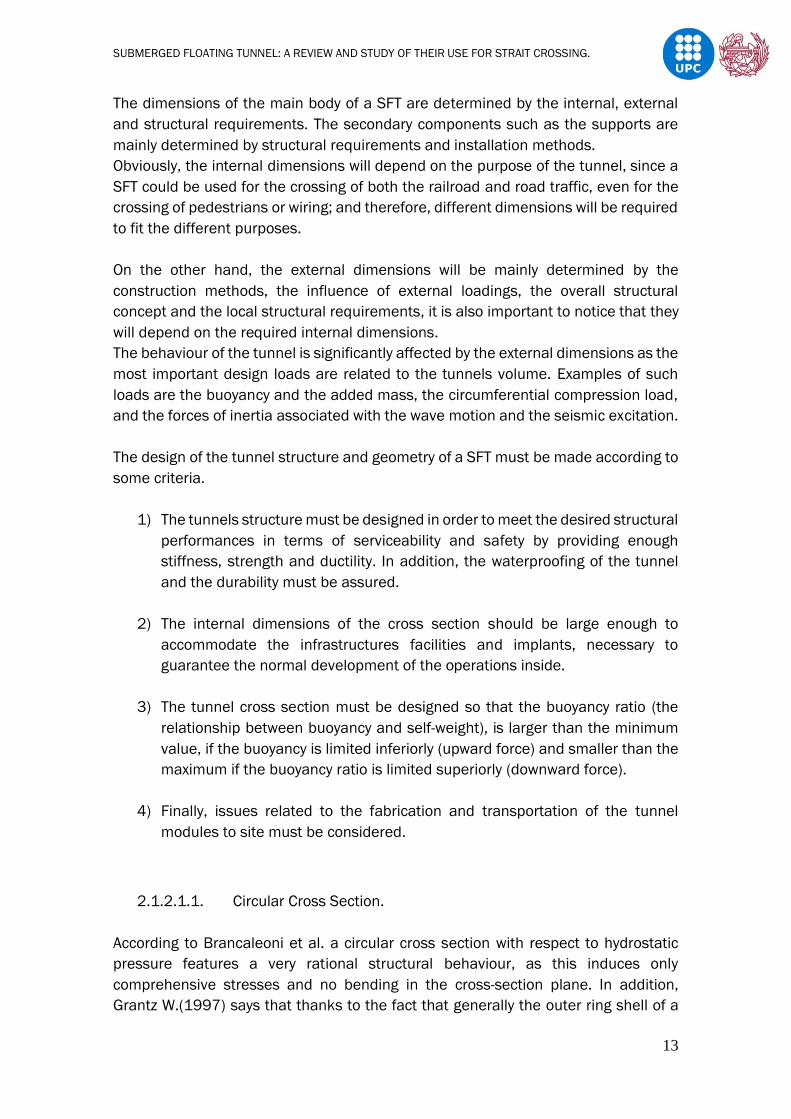
The design of the tunnel structure and geometry of a SFT must be made according to
some criteria.
1) The tunnels structure must be designed in order to meet the desired structural
performances in terms of serviceability and safety by providing enough
stiffness, strength and ductility. In addition, the waterproofing of the tunnel
and the durability must be assured.
2) The internal dimensions of the cross section should be large enough to
accommodate the infrastructures facilities and implants, necessary to
guarantee the normal development of the operations inside.
3) The tunnel cross section must be designed so that the buoyancy ratio (the
relationship between buoyancy and self-weight), is larger than the minimum
value, if the buoyancy is limited inferiorly (upward force) and smaller than the
maximum if the buoyancy ratio is limited superiorly (downward force).
4) Finally, issues related to the fabrication and transportation of the tunnel
modules to site must be considered.
2.1.2.1.1. Circular Cross Section.
According to Brancaleoni et al. a circular cross section with respect to hydrostatic
pressure features a very rational structural behaviour, as this induces only
comprehensive stresses and no bending in the cross-section plane. In addition,
Grantz W.(1997) says that thanks to the fact that generally the outer ring shell of a

SUBMERGED FLOATING TUNNEL: A REVIEW AND STUDY OF THEIR USE FOR STRAIT CROSSING.
14
circular SFT is at leads partially made up of concrete, no longitudinal cracks are
produced by hydrostatic pressure, and so the tunnel waterproofing is not
compromised. Furthermore, regarding hydro-elastic stability issues, Solari (2010)
says that a circular cross section features a good response, as, thanks to its polar
symmetry, it should not be subjected to flutter or torsional divergence phenomena.
Figure 2.5 SFT with circular cross section.(a) Messina Strait crossing(Italy) proposed by ATI-SSST (Scolari et al.,
1989); (b) Hǿgsfjord crossing (Norway) proposed by Aker Norwegian contractors (Skorpa and Ǿstlid, 2001); (c)
Sulafjord crossing (Norway) (Jakobsen et al., 2009).
In addition, another suitable geometrical configuration for the SFT cross section is to
have one or more circular tubes holding the required traffic lanes and other related
facilities connected to each other through a frame substructure and enclosed inside
a streamline shell. This solution was envisaged in the first SFT proposal, developed
by Alan Grant in 1969 for the Messina Strait crossing (Figure 2.6. a) and considered
again later on, such as in the casa of the Northern Japan Exchange Axis (Figure 2.6.
b).
Figure 2.6 (a) Messina Strait (Japan) crossing proposal (Alan Grant, 1969); (b) Northern Japan Exchange Axis.
2.1.2.1.2. Elliptical and Polygonal
When the water conditions are stronger, instead of using circular cross section,
elliptical and polygonal cross sections can be employed. Thanks to the elongation of
the cross section in the horizontal direction, the impact of the hydrodynamic actions
on the tube are decreased. In addition, these shapes provide larger values of stiffness
and strength in the horizontal bending plan, which ensures the good hydrodynamic
behaviour (Panduro J. Omar 2013).
In terms of distribution, it is easier to accommodate the traffic and facilities
requirements in a polygonal than elliptical cross section, but the opposite happens in

SUBMERGED FLOATING TUNNEL: A REVIEW AND STUDY OF THEIR USE FOR STRAIT CROSSING.
15
terms of structural requisites. Furthermore, the production process of the elements
is easier for a polygonal cross section. Some proposals can be seen in Figure 2.7.
Figure 2.7 a) Messina Strait crossing, Italy (ponte di Archimedes S.p.A., 1984); (b) Jintang Strait crossing,
People Republic of China (Faggiano, et al 2001a); (c) Washington Lake crossing, USA (Felch et al, 2001).
2.1.2.1.3. Rectangular
Rectangular cross section would represent the most rational solution, considering the
easiness of the production procedures and the versatility in the organisation of the
internal spaces and facilities. M. Kristofersen et al. says that in terms of functionality
and distribution, the rectangular cross section works better than a circular cross
section but with respect to blast loading, a circular cross section indicates a superior
behaviour.
Under severe conditions, the hydrodynamic behaviour of a complete rectangular
shape is not suitable, the water flow passing through a rectangular SFT would
generate turbulence, thus increase the regime of dynamic pressures induced on the
structure. In order to improve the hydrodynamic behaviour, one solution could be a
rectangular cross section with rounded edges. This solution is recommended when
the magnitude of currents and waves are not large. Another suitable solution in
extreme natural conditions is the employ of hydrodynamic lateral keel, which can be
fabricated of steel shells and trusses. This would improve the fluid dynamic behaviour
of the SFT, preserving the advantage of the rectangular cross section.
Figure 2.8 (a) Sognefjord crossing, Norway (Sweco Norge AS, 2012); (b) Sognefjord crossing, Norway (Cowi AS,
Aas-Jakobsen AS, Johs Holt AS, NGI and Skanska AS, 2012); (c) Tsing Ma Bridge element, Hong kong.

SUBMERGED FLOATING TUNNEL: A REVIEW AND STUDY OF THEIR USE FOR STRAIT CROSSING.
16
2.1.2.2. Materials
When building a marine structure, the main factors when choosing the materials are;
safety, (which would include ensuring structural and functional performances, show
resistance to marine environment etc..) sustainability and economical points of view
(constructional and maintenance cost).
According to Martire G. (2010) the most suitable and rational solutions are the ones
who involve more materials, leading to a multi-layer/multi-material composite
structure. In this way, each material has a particular function that exalts the material
advantages and neutralizes its defects (Faggiano et al. 2001b). In this chapter, the
most recommended materials for the design and construction of a SFT will be
analysed.
These materials are:
a) Steel.
It is commonly employed in offshore structures. It has a very good behaviour against
tensile and compressive efforts at the same time that has a lightweight. On the other
hand, the corrosion is one of the main problems. Eiichi et al (2003) proposes a graph
where in terms of the SFT vertical position, corrosion rate increases or decreases.
New types of steel have been introduced, featuring a lower content of carbon and
resistant to corrosion, in order to improve its performance in maritime applications.
But other types of problems affect them such as the difficulty to produce them in
large scale (Ramasco et al., 1991).
The following table (Table 2.2) shows the different advantages and disadvantages
of steel in marine conditions.
Table 2.1 Distribution of corrosion rate of steel (Ramasco et al., 1991).

SUBMERGED FLOATING TUNNEL: A REVIEW AND STUDY OF THEIR USE FOR STRAIT CROSSING.
17
Table 2.2 Advantages and disadvantages for steel. (Martire, 2010).
b) Concrete (reinforced and/ or prestressed).
Concrete is recommended when a large structural weight is required in order to
stabilize the structure. Concrete in a SFT can contribute to structural strength and
stiffness and provides the weight needed in order to counteract the tunnel buoyancy
(Martire, 2010).
In addition, implementing prestressed concrete can lead to better mechanical
performances and to a larger degree of waterproofing.
Table 2.3. shows the main advantages and disadvantages when employing concrete
in a marine environment.
Table 2.3 Advantages and disadvantages for concrete (Martire, 2010).
c) Aluminium Alloys.
Their main application in offshore structure is in the emerged part of the offshore
platform, its used as to protect the internal structure from corrosion, external impacts
and acts as a waterproofing surface. The following table summarizes its mechanical
properties in a marine environment.
Table 2.4 Advantages and disadvantages for aluminium alloys. (Martire, 2010).

SUBMERGED FLOATING TUNNEL: A REVIEW AND STUDY OF THEIR USE FOR STRAIT CROSSING.
18
d) Rubber Foam.
This material has been considered for the design of a SFT as an external layer as it’s
an impermeable material which would act protecting the inner structure from
corrosion, also is an extremely light material which is able to dissipate the energy
transmitted by external impacts (Grantz,2003). In addition, it is a porous rubber
made up of expanded polyurethane used in the Naval Engineering to increase the
buoyancy of vessels and so it could help stabilize the buoyancy ratio too.
f) High-Performance Fibre Concrete (HPFC)
These materials have appeared in the last decade and are known as high
performance fibre concrete materials. Reinforced concrete is being replaced in water
crossing by HPFC’s due to the fact that HPFC’s have higher tensile strength and crack
resistance and also, they are widely being used because of their good behaviour
against compression, their extent tension strength, their anti-impact resistance, their
waterproofing and their durability.
The following table shows the HPFC’s current properties, also it can be seen how
mechanical parameters increase by using different types of fibre (SINTEF (2009))..
Table 2.5 Properties of high-performance fibre concrete with different fibre.
The table shows some abbreviations which mean:
SRC: Steel fibre reinforced concrete.
GRC: glass fibre reinforced concrete.
PPFC: polypropylene fibre reinforced concrete.
S-PPFC: multi-layered materials, also called Sandwich.
SUBMERGED FLOATING TUNNEL: A REVIEW AND STUDY OF THEIR USE FOR STRAIT CROSSING.
19
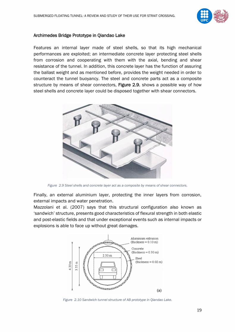
Archimedes Bridge Prototype in Qiandao Lake
Features an internal layer made of steel shells, so that its high mechanical
performances are exploited; an intermediate concrete layer protecting steel shells
from corrosion and cooperating with them with the axial, bending and shear
resistance of the tunnel. In addition, this concrete layer has the function of assuring
the ballast weight and as mentioned before, provides the weight needed in order to
counteract the tunnel buoyancy. The steel and concrete parts act as a composite
structure by means of shear connectors, Figure 2.9. shows a possible way of how
steel shells and concrete layer could be disposed together with shear connectors.
Figure 2.9 Steel shells and concrete layer act as a composite by means of shear connectors.
Finally, an external aluminium layer, protecting the inner layers from corrosion,
external impacts and water penetration.
Mazzolani et al. (2007) says that this structural configuration also known as
‘sandwich’ structure, presents good characteristics of flexural strength in both elastic
and post-elastic fields and that under exceptional events such as internal impacts or
explosions is able to face up without great damages.
Figure 2.10 Sandwich tunnel structure of AB prototype in Qiandao Lake.

SUBMERGED FLOATING TUNNEL: A REVIEW AND STUDY OF THEIR USE FOR STRAIT CROSSING.
20
The Baltimore Harbour Tunnel
An example of a double steel shell Immersed Tunnel, is similar to the one of the
prototypes, with the difference that the outer shell is made out of steel. This external
shell has the same function as the aluminium outer layer from the prototype, to
protect the inner structure from corrosion, impacts and to reduce the hydrodynamic
actions due to incident wave flows (Grantz, 1997). Grantz also in 2003 made a
similar proposal, a double steel shell hull reinforced with reinforced concrete rings on
correspondence with the connections of the tethers and covered with an external
layer of rubber foam, protecting and waterproofing the inner structure.
2.1.2.3. Stability of the Tunnel
The vertical stability of a SFT is a very important consideration. In order to understand
better this concept, Ahrens D. (1997) compares the SFT with other types of tunnels.
For a bored tunnel, the vertical stability is sufficiently ensured by the soil weight on
top of the tunnel. In the case of an immersed tunnel, the vertical stability after the
element is placed on the trench; additional ballast concrete is added in order to
ensure the vertical stability.
Also, for a SFT, the vertical stability has to be ensured by the structure and its support
system as it will never be covered by soil.
In addition, as the SFT in placed between the surface and the seabed, the
appearance of the relationship between buoyancy and self-weight, also known as the
buoyancy ratio, is very important and is crucial to analyse it. In fact, it is a critical
structure parameter tremendously affects the dynamic behaviour of both the tunnel
tube and the cable system (Ahrens D. 1997).
Figure 2.11 The proposed SFT structure by Grantz in 2003
SFT proposed with an outer foam rubber layer.
Figure 2.12 The Baltimore Harbour Tunnel, was constructed on 1957 in Baltimore, Maryland, United States .

SUBMERGED FLOATING TUNNEL: A REVIEW AND STUDY OF THEIR USE FOR STRAIT CROSSING.
21
Two ways of ensuring the vertical stability of a SFT could be:
• Tether system: A situation where there is more buoyancy than weight and so
the structure delivers a resulting upward and positive force, which is taken by
a downward force created by the support system.
• Pontoon system: A situation where there is less buoyancy than weight and so
the structure delivers a resulting downward and negative force, which is then
taken by the upward force created by the support system.
Depending on the site conditions, this relationship will vary, as it will be of a much
more interest to use one type of support system or another. It could exist the
possibility that there is too much traffic in the surface and so a tether system would
be more beneficial and safe (buoyancy more than weight), on the other hand deep
sites can lead to difficulties and so much more expensive projects, as a consequence
a pontoon system would be more viable (weight more than buoyancy).
The resulting load known as residual buoyancy in the tether or the pontoon, will be
the difference between the upward and downward force, or in much more detail, the
algebraic sum of the permanent loads, live loads and the buoyancy of the tunnel. This
load is determined by the internal arrangement and the external dimensions of the
cross section, by the material used and the destination of use.
The third design requisite, where the tunnel cross section must be designed so that
the buoyancy-weight-ratio (BWR) is larger than the minimum value, is of particular
importance in terms of stability and deserves a more detailed discussion.
BWR determines the tension force in the tether section and influences the dynamic
behaviour of SFT structure (Hong Y. et al. 2010).
Firstly, it is important to highlight that the aim of this design condition is to
conveniently limit inferiorly the residual buoyancy.
When a upward (positive) residual buoyancy is assumed, in order to avoid anchorage
slackening due to the induction of environmental actions, it is necessary to ensure a
minimum value of the residual buoyancy in operational conditions. By contrast, for a
SFT where its weight is bigger that the buoyancy force, a different criterion has to be
considered.
The design value of the positive BWR can be evaluated considering the load
combination under vertical dead and live loads valid for the Ultimate Limit State,
defined according to the Eurocode 0 provisions [CEN, EN 1990, 2002] (Panduro J.
2013).
SUBMERGED FLOATING TUNNEL: A REVIEW AND STUDY OF THEIR USE FOR STRAIT CROSSING.
22
Fd= γg.(Gk + Bk) + γq.Qk (γg = 1.35; γq = 1.5) (eq2.1)
Where:
- γg, γq are the partial safety factor for dead and live loads, respectively
- Gk is the characteristic value of the dead loads;
- Bk is the characteristic value of the buoyancy;
- Qk is the characteristic value of the live loads.
Very large values of the lower limit of the BWR were considered in the first studies
and preliminary designs, up to 1,70. Numerical studies confirmed that larger values
of the BWR can improve noticeably the structural performance of the SFTs, when they
are subjected to severe environmental loading scenarios (Martire 2010). In
particular, Brancaleoni et al. (1989) found that increasing the BWR from 1,25 to 1,40
can lead to impressive improvements of the SFT response to extremely severe sea
states.
Table 2.6 Typical design values for buoyancy ratio proposed by Mazzolani et al. and Zhang et al. on their works.
As see in Table 2.5. Mazzolani et al. and Zhang et al. proposed optimal intervals in
which the BWR should be stablished depending in the direction of the residual
buoyancy.
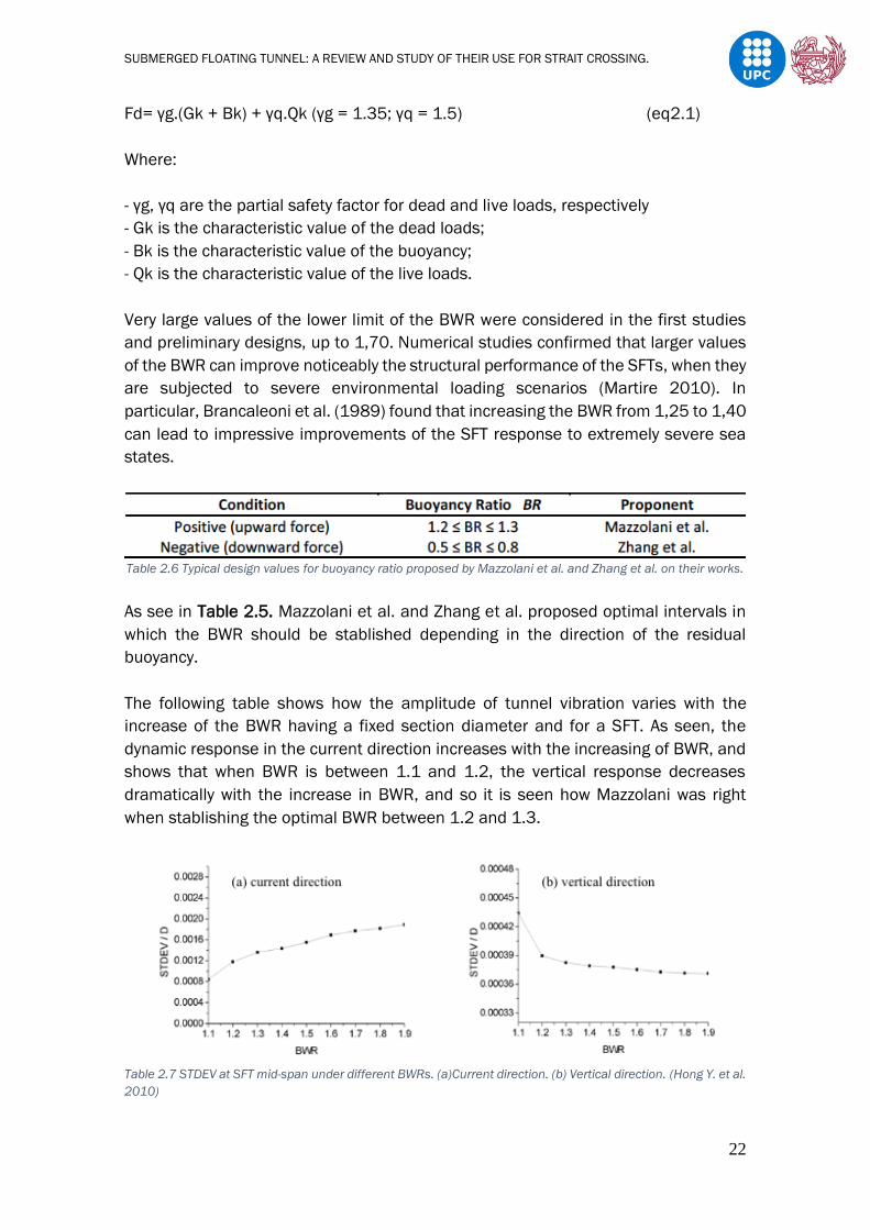
The following table shows how the amplitude of tunnel vibration varies with the
increase of the BWR having a fixed section diameter and for a SFT. As seen, the
dynamic response in the current direction increases with the increasing of BWR, and
shows that when BWR is between 1.1 and 1.2, the vertical response decreases
dramatically with the increase in BWR, and so it is seen how Mazzolani was right
when stablishing the optimal BWR between 1.2 and 1.3.
Table 2.7 STDEV at SFT mid-span under different BWRs. (a)Current direction. (b) Vertical direction. (Hong Y. et al.
2010)

SUBMERGED FLOATING TUNNEL: A REVIEW AND STUDY OF THEIR USE FOR STRAIT CROSSING.
23
Figure 2.13. provides a flow chart which describes the general procedures for the
cross-section design of a SFT. It is being considered both cases, when the tunnels
weight is larger than its buoyancy and opposite, when the resulting force is negative
and when it is positive. In both cases is sought the design value of the buoyancy ratio.
In addition, when the preliminary design does not meet this requirement, the
calculation of ballast could be the solution for satisfying the point.
It also considers the structural analysis of the SFT once the other structural issues of
the tube are designed. In addition, it is taking into account the anchorage of the
support system, which will depend on the decision made after evaluating the natural
conditions of the crossing.
Once the anchorage or support system is designed the static analysis can be made,
both transversal and longitudinal analysis (Mazzolani et al 2008). Then it is designed
the inter-modular joints and shore connection of the SFT for finally realize the
dynamic analysis of the whole structure and meeting the limits of the design
(Remseth S et al. 1999; Xiang Y. et al. 2019).

SUBMERGED FLOATING TUNNEL: A REVIEW AND STUDY OF THEIR USE FOR STRAIT CROSSING.
24
Figure 2.13 Flow chart of the design of a Submerged Floating Tunnel. (Panduro J.Omar 2013).

SUBMERGED FLOATING TUNNEL: A REVIEW AND STUDY OF THEIR USE FOR STRAIT CROSSING.
25
2.1.3. Supports
As mentioned in previous chapters, a SFT can be fixed at the seabed by foundation
systems or on the surface by pontoons, it also exists the possibility of a self-supported
tube where the presence of supports is not needed.
Figure 2.15 Unanchored SFT
In some cases, depending on the site and the environmental conditions, a
combination of pontoons and tethers can be proposed.
2.1.3.1. Pontoons
When the residual buoyancy has a negative value, pontoons are employed. The
weight of the structure is bigger than the buoyancy of it and so an extra force is
needed in order to maintain the SFT stable and in position (vertical and horizontal).
These elements are fixed on the surface of the water crossing.
Their design usually depends on the SFT cross section and the types of boats that will
have to allow the passage. The first and most important issue is the fact of having to
dimension the structure in order to assure the enough buoyancy for supporting its
weight itself and the SFTs.
The separation between pontoons will depend on the issue mentioned before, and
so as it is required to provide enough clearance to allow boats crossing, in some
Figure 2.14 (a) SFT supported by pontoons. (b) SFT anchored to the seabed by tethers.
SUBMERGED FLOATING TUNNEL: A REVIEW AND STUDY OF THEIR USE FOR STRAIT CROSSING.
26
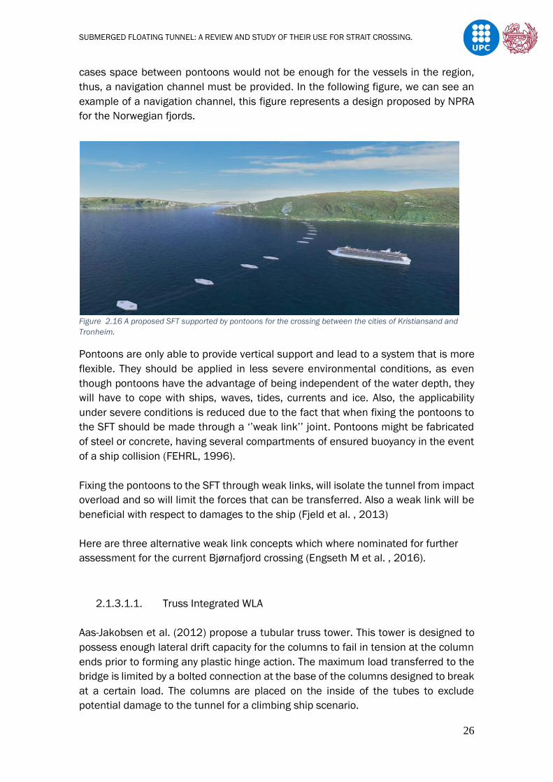
cases space between pontoons would not be enough for the vessels in the region,
thus, a navigation channel must be provided. In the following figure, we can see an
example of a navigation channel, this figure represents a design proposed by NPRA
for the Norwegian fjords.
Figure 2.16 A proposed SFT supported by pontoons for the crossing between the cities of Kristiansand and
Tronheim.
Pontoons are only able to provide vertical support and lead to a system that is more
flexible. They should be applied in less severe environmental conditions, as even
though pontoons have the advantage of being independent of the water depth, they
will have to cope with ships, waves, tides, currents and ice. Also, the applicability
under severe conditions is reduced due to the fact that when fixing the pontoons to
the SFT should be made through a ‘’weak link’’ joint. Pontoons might be fabricated
of steel or concrete, having several compartments of ensured buoyancy in the event
of a ship collision (FEHRL, 1996).
Fixing the pontoons to the SFT through weak links, will isolate the tunnel from impact
overload and so will limit the forces that can be transferred. Also a weak link will be
beneficial with respect to damages to the ship (Fjeld et al. , 2013)
Here are three alternative weak link concepts which where nominated for further
assessment for the current Bjørnafjord crossing (Engseth M et al. , 2016).
2.1.3.1.1. Truss Integrated WLA
Aas-Jakobsen et al. (2012) propose a tubular truss tower. This tower is designed to
possess enough lateral drift capacity for the columns to fail in tension at the column
ends prior to forming any plastic hinge action. The maximum load transferred to the
bridge is limited by a bolted connection at the base of the columns designed to break
at a certain load. The columns are placed on the inside of the tubes to exclude
potential damage to the tunnel for a climbing ship scenario.
SUBMERGED FLOATING TUNNEL: A REVIEW AND STUDY OF THEIR USE FOR STRAIT CROSSING.
27
Figure 2.17 Tuss integrated weak link.
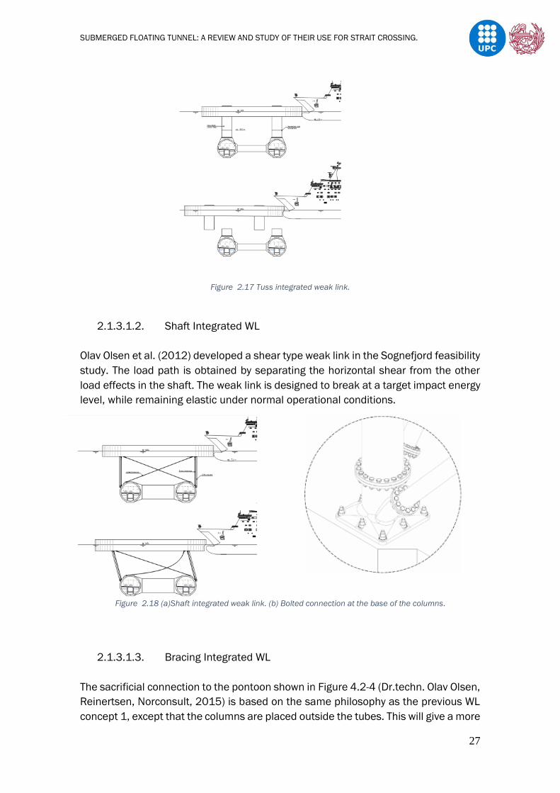
2.1.3.1.2. Shaft Integrated WL
Olav Olsen et al. (2012) developed a shear type weak link in the Sognefjord feasibility
study. The load path is obtained by separating the horizontal shear from the other
load effects in the shaft. The weak link is designed to break at a target impact energy
level, while remaining elastic under normal operational conditions.
Figure 2.18 (a)Shaft integrated weak link. (b) Bolted connection at the base of the columns.
2.1.3.1.3. Bracing Integrated WL
The sacrificial connection to the pontoon shown in Figure 4.2-4 (Dr.techn. Olav Olsen,
Reinertsen, Norconsult, 2015) is based on the same philosophy as the previous WL
concept 1, except that the columns are placed outside the tubes. This will give a more

SUBMERGED FLOATING TUNNEL: A REVIEW AND STUDY OF THEIR USE FOR STRAIT CROSSING.
28
stable platform for a long pontoon, but in return, the diagonal struts will be much
longer which makes them more exposed to Vortex Induced Vibrations (VIV). To
overcome this problem the bending stiffness of the diagonals must be increased.
Figure 2.19 Bracing integrated weak link.
Magnus Engseth et al. (2016) explains how to design a pontoon and analyses how
would a proposed SFT subjected by pontoons and weak links within them, would react
to certain ship and submarine crushes, and from that, makes a capacity evaluation
of the SFT. It is talked about the concept of designing sacrificial elements to dissipate
energy while preserving the integrity of primary structure and presents calculations
that show how a shaft designed to break at a certain load, can reduce the load
transferred.
It is also mentioned that, after an event where severe deformations are caused to
the pontoon shaft and to the pontoon itself, it is possible that the pontoon losses its
ability to support the SFT and for that reason a SFT is designed to withstand loss of
one pontoon in order to maintain its integrity when such an event happens. Finally, it
is explained that to prevent a pontoon from sinking after being separated from the
bridges, pontoons are designed with watertight compartments.
2.1.3.2. Tethers
In the case where the residual buoyancy is bigger than the SFT weight, the SFT must
be stabilized by a foundation system together with a linking system. Obviously, first
the foundation system would be constructed and finally the linking as in the pontoon
system.

SUBMERGED FLOATING TUNNEL: A REVIEW AND STUDY OF THEIR USE FOR STRAIT CROSSING.
29
2.1.3.2.1. Foundation System
There are several foundation systems, which the use of them depend on various
factor, mentioned as follows:
- The seabed condition (type of ground, seismicity and
fouls).
- Depth (constructability point of view).
- Strength to support.
- Cost.
Different foundation systems proposed for SFT such as ;
- Gravity foundations.
- Suction caissons.
- Piers.
- Rock bolts.
Even though, depending on the factors mentioned before, it will be more viable the
use of one system or another, Panduro J. Omar (2013) says that in general any type
of structure that could help to hold the Submerged Floating Tunnel on position can
be considered suitable for employing while stability is guaranteed. In this chapter,
the gravity foundations and suction caissons will be analysed.
2.1.3.2.1.1. Gravity Foundations.
Massive blocks, which are designed to have enough, weigh in order to
counterbalance the residual buoyancy of the SFT. Main problems related to gravity
foundations are the need of a superficial layer with good mechanical properties and
the low horizontal bearing capacity, which can lead to displacement and SFT stability
problems (i.e. severe seismic events produce a combination of vertical and horizontal
dynamic forces on the foundation which might produce permanent horizontal
displacement on it leading to a modification on the geometrical configuration of the
anchoring system) (Martire, 2010).
These elements generally consist on initially empty concrete boxes that are precast
in a dry yard and that thanks to their own buoyancy capacity, are transported until
their correspondence place. There, they are filled with concrete and then sinked until
the seabed, where finally act as gravity foundations.

SUBMERGED FLOATING TUNNEL: A REVIEW AND STUDY OF THEIR USE FOR STRAIT CROSSING.
30
Figure 2.20 Sequence of transport and erection of foundation (Mazzolani et al. 2007).
2.1.3.2.1.2. Suction Caissons
Suction caissons are most new form of offshore foundation, which have greater
advantages than the conventional ways, mainly being easier to install and to remove
during decommissioning. Nowadays, suction caissons are widely used for anchoring
large offshore installations at great depths.
This technology was developed in order to maintain the installations stability under
sever conditions where the anchorage suffered from large tensioning due to waves
and stormy weather. The suction caissons work very well in a seabed with soft clays
or other low strength sediments. It is important to notice that the installation is much
easier than piles, which must be hammered into the ground and so less expensive.
The installation of a suction caissons starts by its own weight penetration to the
ground and then forced to the design penetration by pumping water out of the caisson
in order to create under pressure/suction within the caisson. This difference in
pressure results in a downward force on the exposed end of the caisson, which slowly
pushed the caisson into the seafloor.
Figure 2.21 Suction Caisson installation (Arup).

SUBMERGED FLOATING TUNNEL: A REVIEW AND STUDY OF THEIR USE FOR STRAIT CROSSING.
31
2.1.3.3. Linking System
In order to attach the SFT to either the foundation or the pontoon, the most common
way is by using steel tethers as cables, bars or tubes. This system is usually conceived
as a series of cables groups, disposed in the tunnel cross-section plane and repeated
along the tunnel axis with a fixed inter-axis.
There are several types of mooring cable arrangements in order to support a SFT, the
following picture shows some of the most proposed arrangements.
Figure 2.22 Tether configurations.
Naik Muhammad et al. (2017) evaluates the performance of a SFT supported by
the three different cable configurations shown in Figure 2.22. and concludes after
analysing the dynamic and the static response of the SFT, that groups made up of
two vertical cables configuration are effective only in the vertical direction, thus
being suitable only in a calm environment; groups made up of four inclined cables
are the most effective.
Also, Hong Y. et al. (2010) investigates the slackening phenomena; their study
focuses on the relationship between relative dynamic tension and tether angle, where
it is concluded that at first the dynamic tension increases sharply and then decreases
and that if the angle is larger than 30º, the response becomes stable. Finally, the
dynamic tension reaches its peak value around the tether angle of 15º.
Table 2.8 Effect of tunnel outer diameter on SFT dynamic response (Hong Y et al. 2010).
Table 2.8 indicates that the dynamic response in the current direction increases as
tunnel outer diameter increases (or BCR increases, stiffness coefficient of tether

SUBMERGED FLOATING TUNNEL: A REVIEW AND STUDY OF THEIR USE FOR STRAIT CROSSING.
32
system) increases, whereas in the vertical direction, the dynamic response increases
as the outer diameter of tunnel segment decreases (or BCR decreases).
Table 2.9 Effect of tether system stiffness on SFT dynamic response (Hong Y et al. 2010).
Table 2.9 shows that the dynamic responses on both current and vertical direction
increases as the tether system stiffness decreases or BCR increases (stiffness
coefficient of tether system). Even though net buoyancy and tether stiffness are
essential factors with regard to SFT stability. From Table 2.8 and Table 2.9 can be
seen that BCR is not a characteristic factor with respect to SFT dynamics (Hong Y. et
al., 2010).
Obviously, the cables must be able to resist the tensile force generated by the
residual buoyancy. Therefore, given the permanent residual buoyancy and the cable
length, it is chosen the diameter of the cables which determines it axial tensile
strength, stiffness and other parameters such as the ratios between initial axial force
and cables strength and weight. Martire (2010) considers that these two ratios are
of great importance for the performance of each cable, as they define the axial force
increment due to live or environmental loads that can be carried by the cable and the
importance of non-linear effects in the cable response.
So, for the design of the anchoring system made out of steel cables, it’s important to
pay special attention to the geometrical configuration of the cable system, the
diameter to be assigned to the cables and the restraint condition to provide at the
ends of the cables.
2.1.4. Joints
The whole structure behaviour of a SFT has a great dependence in the joints between
modules, as they must guarantee the linking between each of them as well as the
whole tightness of the tube. They must assure the correct structural behaviour for
which the SFT is designed. If the design allows displacement along the tube a flexible
joint must be employed or if not a rigid joint has to be adopted. Finally, special joints

SUBMERGED FLOATING TUNNEL: A REVIEW AND STUDY OF THEIR USE FOR STRAIT CROSSING.
33
must be located at the end and entrance of the SFT, as they must allow different
displacements according to the design carried on.
There are two ways of tube joint based on stiffness and deformation: rigid joint and
flexible joint. Table 2.10 Enumerates differences of two types of joints.
Table 2.10 Comparison between rigid and flexible joints. (Zhang et al., 2010).
Figure 2.23 (a) Schematic drawing of rigid joint design (b) Schematic drawing of flexible joint design.
On the other hand, one of the most relevant issues in the design of a SFT is the
configuration of the shore connections, as in these zones a transition between two
different states of equilibrium happen (FEHRL, 1996):
- The tunnel in equilibrium with the ground pressures and,
eventually with the seismic pressures induced by
earthquakes.
- The tunnel in equilibrium with the water actions, with the
retaining forces induced by the supports and if the SFT is
anchored to the seabed, to the seismic actions.
The following figure shows two proposed shore connections for the Messina Strait
crossing situated in Italy by the ENI Consortium.
SUBMERGED FLOATING TUNNEL: A REVIEW AND STUDY OF THEIR USE FOR STRAIT CROSSING.
34
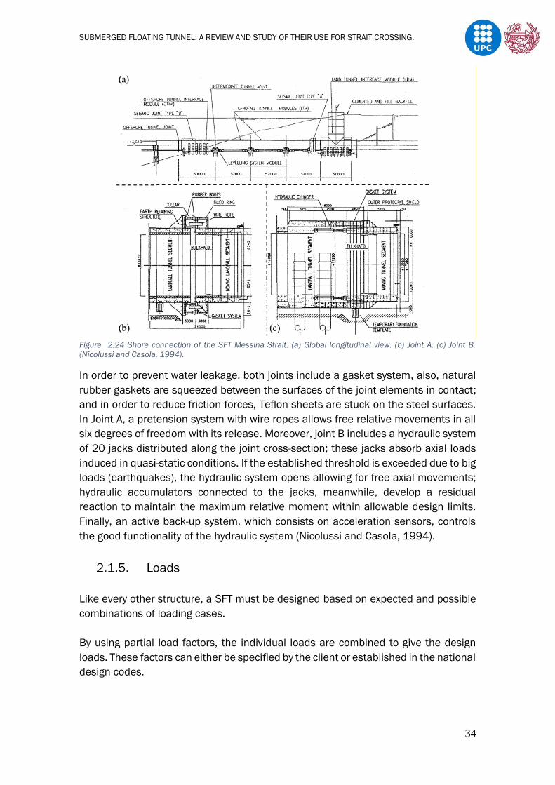
Figure 2.24 Shore connection of the SFT Messina Strait. (a) Global longitudinal view. (b) Joint A. (c) Joint B.
(Nicolussi and Casola, 1994).
In order to prevent water leakage, both joints include a gasket system, also, natural
rubber gaskets are squeezed between the surfaces of the joint elements in contact;
and in order to reduce friction forces, Teflon sheets are stuck on the steel surfaces.
In Joint A, a pretension system with wire ropes allows free relative movements in all
six degrees of freedom with its release. Moreover, joint B includes a hydraulic system
of 20 jacks distributed along the joint cross-section; these jacks absorb axial loads
induced in quasi-static conditions. If the established threshold is exceeded due to big
loads (earthquakes), the hydraulic system opens allowing for free axial movements;
hydraulic accumulators connected to the jacks, meanwhile, develop a residual
reaction to maintain the maximum relative moment within allowable design limits.
Finally, an active back-up system, which consists on acceleration sensors, controls
the good functionality of the hydraulic system (Nicolussi and Casola, 1994).
2.1.5. Loads
Like every other structure, a SFT must be designed based on expected and possible
combinations of loading cases.
By using partial load factors, the individual loads are combined to give the design
loads. These factors can either be specified by the client or established in the national
design codes.

SUBMERGED FLOATING TUNNEL: A REVIEW AND STUDY OF THEIR USE FOR STRAIT CROSSING.
35
The following loads are the ones that usually must be considered during the design
stage:
1. PL (Permanent Loads): Weight of the various structural and non-structural
component (Total dead weight), the water buoyancy and the hydrostatic
pressure. This load will be permanently present during the lifetime of the
structure. The resulting force in the tether or pontoon system will be the
difference between the buoyancy and total dead weight.
The self-weight per unit of the cross section of the SFT can be calculated with
the following equation (Panduro J.Omar 2013).
𝑊𝐷 = Σ𝛾𝑚𝐴𝑚 + 𝑊𝑓 (eq2.3)
Where:
WD : Weight of the structure per unit (kg/m).
𝛾𝑚 : Specific weight of each material involved in the cross section (kg/m2).
Am : Area of each material involved in the cross section (m2).
Wf : Facilities weight (kg/m).
The water buoyancy also known as Archimedes buoyancy is obtained with the
following equation.
𝐵𝑘 = 𝛾𝑤𝐴𝑡𝑜𝑡 (eq2.4)
Where:
𝛾𝑤 : Specific weight of water. This value is related to the salinity and temperature
of the water. The salinity is generally measured as part per million (ppm).
Atot : Total area of the SFT cross section.
Finally, the algebraic sum of the self-weight of the structure and the water
buoyancy gives the residual buoyancy of the tunnel. This value is a fundamental
factor for the stability of the structure. The calculation can be made with the
following equation.
𝑅𝐵𝑘 = 𝐵𝑘 − 𝐴𝑡𝑜𝑡 (eq2.5)
The accuracy when determining this force is very important, and in order to
ensure that, the following uncertainties must be taken into account (Ahrens D.
1997).
- Tolerances in geometry and dimensions: During the design
stage, the acceptable tolerances in geometry and

SUBMERGED FLOATING TUNNEL: A REVIEW AND STUDY OF THEIR USE FOR STRAIT CROSSING.
36
dimensions, depending on the choice of the construction
method, must be established. During construction, an
experienced contractor keeps the tolerances under control.
After construction, this parameter is no longer variable. In
case of significant variations from the weight design value,
the ballast quantity can be modified at the end of the
construction.
- The specific weight of concrete: Although the specific
weight of the concrete will vary during the construction, it
can be easily measured. The acceptable range has to be
established beforehand. After the construction, this
parameter is known exactly. The weight of the structure may
change slightly over the time, as the concrete absorbs
water.(Alteration minimal in comparison to the capacity of
the support system).
- The specific gravity of water: The range in the specific
gravity of the water will be particular of the site, and should
be obtained at an early stage in the design process. The
variation in buoyancy resulting from the change in the
specific gravity of the water is permanent variable, and may
have special importance in coastal areas, where the
amount of river runoff or melting ice or snow can change the
value rapidly.
- The amount and stability of marine growth: marine growth
is known to concentrate at the sea floor and at the surface.
If the SFT is not located in the critical surface layer, the
effects of marine growth will be minor. However, where such
growth does occur, it will increase the weight and the
current resistance. Therefore, accurate predictions of the
amount of marine growth are required.
The aforementioned uncertainties lead to time variations of the residual
buoyancy; in order to keep these variations under control, avoiding negative
effects on the structural stability, it is possible to use water as ballasting
material (or part of it) and counteract the weight changes by varying the
amount of ballast water. This operation can be easily made through hydraulic
pumps (Martire, 2010).
2. FL (Functional Loads) or variable loads: Are those caused by the usage of the
structure, in a SFT, which are due to traffic, changes in ballast conditions and
the variable loads during construction.

SUBMERGED FLOATING TUNNEL: A REVIEW AND STUDY OF THEIR USE FOR STRAIT CROSSING.
37
Depending on the destination of use of the SFT, different functional loads will
be produced. As it is known a SFT is proposed for pedestrian, roadway, railway
or combination of these.
In a single day, the amount of traffic in the tunnel suffers great variations and
so defining an associated load is quite difficult. Codes such as Eurocode 1 , part
3, UNI ENV 1991-2, 1991 or Norma española. UNE-EN 1991-2. CAPÍTULO 4.
ACCIONES DE TRÁFICO RODADO Y OTRAS ACCIONES ESPECÍFICAS PARA
PUENTES DE CARRETERA define conventional loading conditions determined on
the basis of statistical data gathering and analysis; these codes are intended to
reproduce most critical stress conditions produced by traffic loads on the
structure.
The following table shows some load values proposed by Martire (2010)
according to the SFTs destination of use.
Table 2.11 Variable load values for SFT depending on its destination of use.
3. DL (Deformation Loads): These are cause by geometric changes in the structure
itself; these loads are usually associated to the material properties involved.
Some of the causes of deformation loads are due to post and pre-tensioning,
temperature variations, differential settlements, shrinkage, as mentioned
before ship or submarine collision etc...
4. Hydrodynamic loads: Hydrodynamic actions due to the interaction between the
water and the structure in presence of waves and currents, it often represents
the most important environmental load for a SFT.
The effects of the hydrodynamic actions for a circular cross section are
evaluated, through both static and dynamic analyses, by means of the Morison.
(Mazzolani F.M. et al. 2008)
F= FD(t)+FI(t) = 1
2ρ𝑊𝐷𝐶𝐷𝑢(𝑡)2 + 𝜌𝑊
𝜋𝐷2
4𝐶𝐼𝑎(𝑡) (eq2.6)
with the following meaning of the symbols:
- F = Hydrodynamic force
- FD= Drag force, depending on the velocity vector u(t);
- FI= Inertia force, depending on the acceleration vector a(t);

SUBMERGED FLOATING TUNNEL: A REVIEW AND STUDY OF THEIR USE FOR STRAIT CROSSING.
38
- ρw= Water mass density;
- D = Tunnel external diameter;
- CD = Drag coefficient
- Ca= Added mass coefficient where for a cylinder = 1.0.
- CI= Inertia coefficient =1 + Ca =2.0, taking into account the added mass
of the water surrounding the tunnel, which participates to the tunnel
motions (Efstathios Konstantinidis 2017);
- u(t) = Velocity vector, equal to the relative velocity between the fluid
particles and the tunnel;
- a(t) = Acceleration vector, equal to the relative acceleration between
the fluid particles and the tunnel.
Figure 2.25 Drag coefficients.
4.1. Currents: There can be different types of currents in waterways, those
generated by wind and those generated by tide variation. Wind blowing over
the water surface transfers energy to it, creating water motion. By contrast,
the rise and fall of the water level due to tides, leads to horizontal water
motion. Obviously, it will depend on the site whether if current will create a
larger or smaller load.
Usually water motion due to currents take place in the horizontal plane and
can be assumed constant, as small variations in its velocity occur in a
sufficiently long-time period. However short and long-term fluctuations
around the velocity mean value occur, therefore when the former ones are
significant they should be considered. Generally, for design purposes, water
current is modelled as a horizontal velocity distribution along the water
SUBMERGED FLOATING TUNNEL: A REVIEW AND STUDY OF THEIR USE FOR STRAIT CROSSING.
39
depth; this distribution can be roughly assumed to be constant or, more
generally, can be represented by as a polyline, thus requiring observed data
relative to the current velocity at the depths of the polyline vertices (Martire,
2010).
An analytical distribution often adopted for the current velocity can be shown
as:
𝑉𝐶(𝑧) = 𝑉𝑇 (𝑧+𝑑
𝑑)
1
7+ 𝑉𝑊 (
𝑧+𝑑
𝑑) (eq2.7)
Where:
VC (z) : Current velocity at a depth equal to z (z axis with the origin in the
free surface and directed upwards).
VT : Surface current velocity generated by tides.
VW : Surface current velocity generated by wind.
4.2. Waves: Waves differ from currents because an oscillating motion of the
water particles characterizes them. Can be of two types, they can be either
generated by wind due to the wind blowing over the surface, or they can be
created by the force of gravity acting on small differences in density which
keep water particles in motion, known as internal waves.
- Wind generated waves: When directly being generated by the local winds, a
wind wave system is called a wind sea. On the contrary, wind generated waves
that are not affected by the local wind at that time and have been generated
elsewhere, or some time ago, are called swells.
- Internal waves: Different density can exist between two fluids or between
different parts of the same fluid because of a difference in temperature,
salinity, or concentration of suspended sediment.
Although internal waves can be important and induce significant loads on
marine structures, in most cases wave water motion is made of wind
generated waves (Martire, 2010).
The size of the wind waves depends on three variables: the wind speed, the
wind duration and the fetch the exposure of the site to wind action.

SUBMERGED FLOATING TUNNEL: A REVIEW AND STUDY OF THEIR USE FOR STRAIT CROSSING.
40
Small amplitude waves in deep water acquire a sinusoidal form, by contrast
in shallow water the wave crests become steeper and the troughs (minimum)
flatter, the form tending to become trochoidal.
Figure 2.26 Sinusoidal wave.
Figure 2.27 Trochoidal wave.
In deep water a single sinusoidal wave can be described by three parameters
(CIRIA Underwater Group, 1978).
- Wave period(TW ): The temporal distance between two crests or two troughs.
- Wave height: (HW ) : The vertical distance from trough to crest.
- Wave length( 𝜆𝑊): The geometric distance between two crests or two troughs,
measured in the direction of propagation of the wave. Wave length is closely
associated to wave period and also to wave celerity, being 𝜆𝑊 = c · TW their
relationship. Moreover, there is a first order relationship between 𝜆𝑊 and TW.
𝜆𝑊 = 1.56 · TW2 (eq2.8)
(𝜆𝑊 in metres and TW in seconds)
In order to describe the motion of water particles due to waves, several
theories have been developed, generally focusing on the determination of the
velocity potential, satisfying the Laplace Equation and assuming an
irrotational and incompressible fluid. The following table explains the most
common theories used to carry out the hydrodynamic analysis due to wave
loads.

SUBMERGED FLOATING TUNNEL: A REVIEW AND STUDY OF THEIR USE FOR STRAIT CROSSING.
41
Table 2.12 Linear and non-linear wave theories features (Panduro J.Omar 2013).
Choosing the right and adequate wave theory, will depend on the different
wave parameters. In fact, each wave theory can be considered reliable in
different fields of application in terms of wave period, height and seabed
depth. In Figure 2.28. can be seen the different behaviours of each theory.
Figure 2.28 Graphical representation of the different wave theories. (Medina, 2009).
Theory Features Application
Airy Linear Wave Theory
also called Sinusoidal
The wave height Hw is small
(Sarpkaya and Isaacson, 1981).
When the wave height Hw is
considerably smaller tan both the
wave length Lw and the seabed
depth d. (Sarpkaya and Isaacson,
1981).
Stokes theory
The considered wave is
not too steep and water
depth is not too small
(Sarpkaya and Isaacson,
1981)
When the wave height-to-length
ratio is largely lower than
one (Hw/Lw<<1; (Peregrine, 1972))
and when the wave length
Lw is less than 8 times the water
depth d (Laitone, 1962).
Cnoidal Wave Theory
Waves with very steep and sharp
crests and flat roughs.
In shallow waters. When
d/Lw < 0.05.
Solitary Wave Theory
large wave length
compare to the height
When d/Lw < 0.05
Linearized Long Wave or the
Trochoidal Theory
Circular particle orbits, rotational
fluid and trochoidal wave surface
profile (Gerstner, 1802; Rankine,
1863).
It serves as a link from linear theory
to the finite amplitude oscillation
wave theory (Wilson, 2003) .

SUBMERGED FLOATING TUNNEL: A REVIEW AND STUDY OF THEIR USE FOR STRAIT CROSSING.
42
There are many diagrams defining the field application of the various wave
theories. In Figure 2.29. the range of validity of the different theories of wave.
Figure 2.29 Range of validity for the wave theories. (Le Méhauté, 2008).
Bernt Jakobsen (2010) says that it is not so much the difference in wave
heights that causes higher wave loads on the structure from the sea waves,
but more the difference in wave periods. Figure 2.30. illustrates the effect of
different wave periods on the wave force as a function of the depth at which
the tube is located.
Figure 2.30 Wave force as a function of wave period and depth (Bernt Jakobsen ,2010).

SUBMERGED FLOATING TUNNEL: A REVIEW AND STUDY OF THEIR USE FOR STRAIT CROSSING.
43
5. Earthquake or seismic loads: Strong ground motion due to release of energy
from the accumulated earth's crust apart from volcanic and tectonic activities,
which originate mainly at the edges of the plate. Special attention should be
paid to the tunnel shore connections and also to the anchoring system as the
seismic loads will propagate through (downwards residual buoyancy). A SFT
supported from bed level by means of any anchoring method would suffer the
seismic loads much like a bridge, but supported in any other way could be
almost independent of seismic loads. This does not mean that seismic events
can be ignored. So, it is necessary to assure that every structural component
supports safely extreme seismic events. (Ahrens D. 1997)
Xiao J. et al (2010) made a study of the seismic response of the Submerged
Floating Tunnel with different types of connections between the ends of SFT and
the shore, including the rigid connection, hinged connection, elastic bearing
connection, bi-linear elastic bearing connection, and passive isolation
connection. Hi concluded firstly, that the hinged connection system can greatly
reduce the seismic response with respect to the rigid connection, and finally,
that the elastic bearing and passive isolation connection in comparison with the
hinged connection by choosing proper parameters of the bearings can be much
more effective.
Figure 2.31 (a) Hinged connection. (b) Elastic bearing connection.
Figure 2.32 Passive isolated connection.

SUBMERGED FLOATING TUNNEL: A REVIEW AND STUDY OF THEIR USE FOR STRAIT CROSSING.
44
6. AL (Accidental Loads) : Accidental loads, are not meant to happen, but they do
happen from time to time, so they must be considered, and specified, a rational
way of dealing with these loads must be studied. Explosions inside or outside
the tube, loss of buoyancy, fire from burning cars or fluids, failure within the
support system are some of the accidents that could cause this type of loads.
On the next table can be seen several studies related to accidental events and
how may they affect a SFT.
Table 2.13 Studies related to accidental event which could occur on a SFT. (Panduro J.Omar 2013).
2.1.6. Limit States
The SFT design method can be based the semi-probabilistic limit state approach,
using partial safety coefficients on both loads and strength of materials.
The semi-probabilistic approach divides the design into the following design limits
states:
SLS (Serviceability Limit State): These conditions are set to ensure that the whole
structure meets the necessary criteria with regard to deflections, crack widths,
factors of safety, accelerations etc.
ULS(Ultimate Limit State): This condition is set to confirm that the structure has the
necessary margin of strength to survive factored loads and load combinations, with
the factors being set to provide acceptable risk of failure. The factors must also be
sufficient to ensure after an unfeatured event, that the structure is capable of
continuing to operate satisfactorily.
FLS(Fatigue Limit State): Some materials lose strength due to repeated loading. The
FLS is required to account this fact. By computing the accumulated damage in the
material and checking the computed life of the structure against the operational life
the sensitivity of certain components of the structure can be established.

SUBMERGED FLOATING TUNNEL: A REVIEW AND STUDY OF THEIR USE FOR STRAIT CROSSING.
45
2.1.7. Construction Methods.
2.1.7.1. Incremental Construction and Launching.
In this method, the construction takes place at one of the abutments which are
modified and increased in size to accommodate the construction site and the
associated plant, equipment and materials.
The tube is constructed in consecutive sections on an inclined skid way in the
abutment. After each section is completed, the tube is moved forward into the water,
over the length of one section. For this reason, the segment is constructed in saddles
and pushed forward by hydraulic jacks. Before it is pushed through the gate, the tube
is coupled to the previous segments with pretension cables. The part of the tube
pushed out into the water must be kept under control. A temporary cable system
and/or a pontoon support system is a likely method for this purpose.
If the pontoons are used for vertical support during pushout, a shore-based cable
system may be needed to keep the SFT under control in the horizontal direction. The
stiffness of the cable system in relation to the stiffness at the pushout gate will
require careful consideration. New pontoons are connected to the tube as it moves
forward. The pontoons, which may be temporary or permanent, follow the structure
across the waterway.
An alternative would be to use final tethers, installed in advance and supported by
temporary pontoons. To allow the tube to move, a special guidance and support
system is needed at the top end of the tethers. It may be possible to install rollers,
guidance plates or hydro jet bearings in a saddle, which may be temporary or which
may become part of the final construction. As the tube is pushed forward, it meets
the guidance structure. The tether tension is then provided by the buoyancy of the
tube (Ahrens D. 1997).
Figure 2.33 Incremental construction and launching of SFT elements (Ahrens D. 1997).

SUBMERGED FLOATING TUNNEL: A REVIEW AND STUDY OF THEIR USE FOR STRAIT CROSSING.
46
2.1.7.2. Element Construction and Launching
The SFT elements are constructed in a dock. After all, or a number of elements have
been completed, the dock is flooded and the elements are towed to the site.
Bulkheads used to seal the ends and to maintain positive buoyancy during
construction, are joined at the site. The length of each element is determined partly
by the structural capabilities of the SFT (the designed distance between the supports)
and partly by the available length of existing ship docks, slipways or construction
docks.
After reaching the site, the installation barge supports the element during assembly
and lowering to the intended depth: At each joint location, a set of tethers is pre-
installed and coupled in a horseshoe-shaped support. The element is lowered under
the support while temporarily pulling the support aside.
After the element has been fitted into the predetermined tether support system, it is
de-ballasted, causing the load to transfer from the installation barge to the tether
system. During this process, the length of the tethers is adjusted at the support shoe
to prevent unacceptable deflections of both tethers, the position of the new element
and of previous elements.
An initial watertight seal is provided by a rubber gasket. After de-watering the area
between bulkheads, the permanents join between the two elements is made and
post-tensioned to obtain full structural strength. The rubber gasket has only a
temporary function during construction.
Several solutions may be used for the final connection between the tunnel and the
tethers. These connections depend on the location of the connection i.e. whether
they are external or within special chambers added to the tunnel. It also depends on
whether the preference is to connect the tethers first to the anchor points on the bed
or to the elements before it is lowered (Ahrens D. 1997).
Figure 2.34 SFT elements being towed to the site.

SUBMERGED FLOATING TUNNEL: A REVIEW AND STUDY OF THEIR USE FOR STRAIT CROSSING.
47
Figure 2.35 Type of installation on site (Ahrens D. 1997).
2.2. Suspension Bridges
A suspension bridge is a type of bridge, which has suspended cables between towers,
in addition to vertical suspender, cables that carry the weight of the deck below,
destined for the crossing of traffic.
The basic structural components of a suspension bridge system include
girders/trusses, the main suspension cables, main towers, and the anchorages for
the cables at each end of the bridge.
Figure 2.36 Akashi-Kaikyō Bridge, Japan.
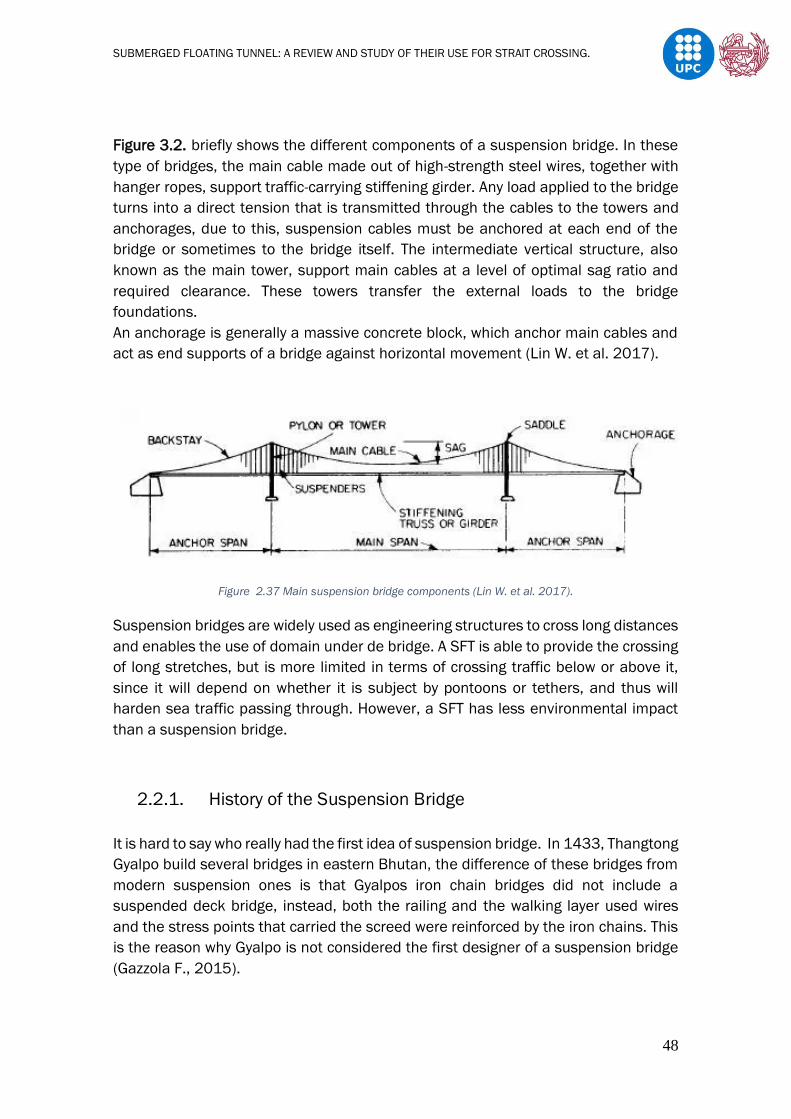
SUBMERGED FLOATING TUNNEL: A REVIEW AND STUDY OF THEIR USE FOR STRAIT CROSSING.
48
Figure 3.2. briefly shows the different components of a suspension bridge. In these
type of bridges, the main cable made out of high-strength steel wires, together with
hanger ropes, support traffic-carrying stiffening girder. Any load applied to the bridge
turns into a direct tension that is transmitted through the cables to the towers and
anchorages, due to this, suspension cables must be anchored at each end of the
bridge or sometimes to the bridge itself. The intermediate vertical structure, also
known as the main tower, support main cables at a level of optimal sag ratio and
required clearance. These towers transfer the external loads to the bridge
foundations.
An anchorage is generally a massive concrete block, which anchor main cables and
act as end supports of a bridge against horizontal movement (Lin W. et al. 2017).
Figure 2.37 Main suspension bridge components (Lin W. et al. 2017).
Suspension bridges are widely used as engineering structures to cross long distances
and enables the use of domain under de bridge. A SFT is able to provide the crossing
of long stretches, but is more limited in terms of crossing traffic below or above it,
since it will depend on whether it is subject by pontoons or tethers, and thus will
harden sea traffic passing through. However, a SFT has less environmental impact
than a suspension bridge.
2.2.1. History of the Suspension Bridge
It is hard to say who really had the first idea of suspension bridge. In 1433, Thangtong
Gyalpo build several bridges in eastern Bhutan, the difference of these bridges from
modern suspension ones is that Gyalpos iron chain bridges did not include a
suspended deck bridge, instead, both the railing and the walking layer used wires
and the stress points that carried the screed were reinforced by the iron chains. This
is the reason why Gyalpo is not considered the first designer of a suspension bridge
(Gazzola F., 2015).

SUBMERGED FLOATING TUNNEL: A REVIEW AND STUDY OF THEIR USE FOR STRAIT CROSSING.
49
Figure 2.38 Picture of the Chushul Chakzam suspension bridge (Gazzola F., 2015).
The Italian engineer Fausto Veranzio is known to be the first one to design a modern
suspension bridge in 1595. Veranzio proposed an iron bridge (Pons Ferreus) which
is somehow a combination between a suspension bridge and a cable-stayed bridge.
Even though, this bridge was never build.
Figure 2.39 Picture of the Pons Ferreus by Fausto Veranzio (1595) (Gazzola F., 2015).

SUBMERGED FLOATING TUNNEL: A REVIEW AND STUDY OF THEIR USE FOR STRAIT CROSSING.
50
However, it was not until two centuries later in 1801, when it is thought to have been
erected the first suspension bridge, using wrought iron chains with a level deck,
known as Jacob Creek Bridge situated in Pennsylvania. This bridge, was built by the
Irish judge and engineer James Finley.
Figure 2.40 View of the Jacob Creek Bridge (1801). (Gazzola F., 2015).
2.2.2. Suspension Bridge Classification.
Suspension bridges can be classified according to:
- Span Number
- Stiffening Grinders
- Suspenders
- Anchoring Conditions
2.2.2.1. Span Number
Nowadays, there can be several types of suspension bridges based on the number
of spans and towers. Single-span, two-span, three-span or multi span suspension
bridges. Among them, the most commonly used in engineering practice is the three-
span suspension bridges with two main towers.

SUBMERGED FLOATING TUNNEL: A REVIEW AND STUDY OF THEIR USE FOR STRAIT CROSSING.
51
Figure 2.41 Suspension bridge classification according to span number. (a) Single-span. (b) Three-span. (c) Multi-
span (M. De Miranda, 2016).
Typical single-span suspension bridges could be the Tsing Ma Bridge in Hong Kong
and the Pingsheng Bridge in Guangdong.
Figure 2.42 Tsing Ma Bridge in Hong Kong
Figure 2.43 Pingsheng Bridge in Guangdong.
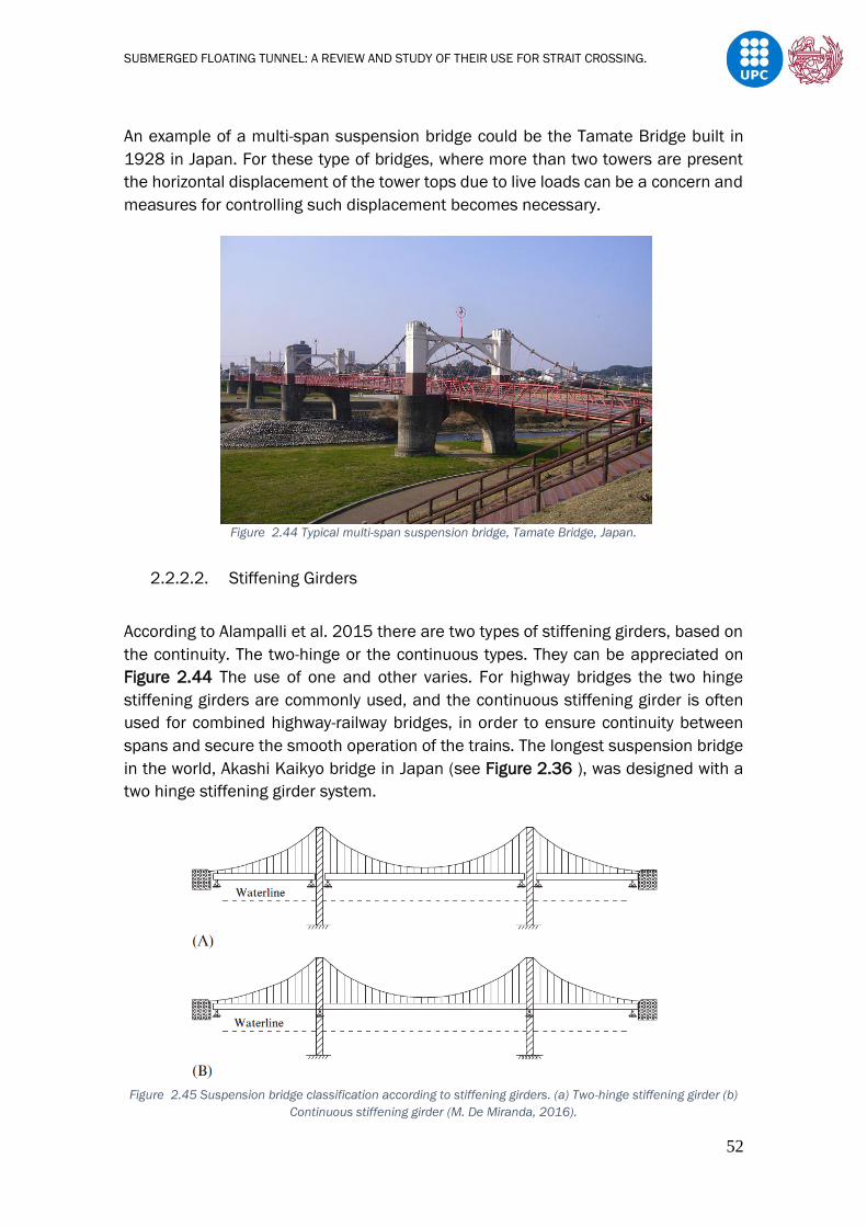
SUBMERGED FLOATING TUNNEL: A REVIEW AND STUDY OF THEIR USE FOR STRAIT CROSSING.
52
An example of a multi-span suspension bridge could be the Tamate Bridge built in
1928 in Japan. For these type of bridges, where more than two towers are present
the horizontal displacement of the tower tops due to live loads can be a concern and
measures for controlling such displacement becomes necessary.
Figure 2.44 Typical multi-span suspension bridge, Tamate Bridge, Japan.
2.2.2.2. Stiffening Girders
According to Alampalli et al. 2015 there are two types of stiffening girders, based on
the continuity. The two-hinge or the continuous types. They can be appreciated on
Figure 2.44 The use of one and other varies. For highway bridges the two hinge
stiffening girders are commonly used, and the continuous stiffening girder is often
used for combined highway-railway bridges, in order to ensure continuity between
spans and secure the smooth operation of the trains. The longest suspension bridge
in the world, Akashi Kaikyo bridge in Japan (see Figure 2.36 ), was designed with a
two hinge stiffening girder system.
Figure 2.45 Suspension bridge classification according to stiffening girders. (a) Two-hinge stiffening girder (b)
Continuous stiffening girder (M. De Miranda, 2016).
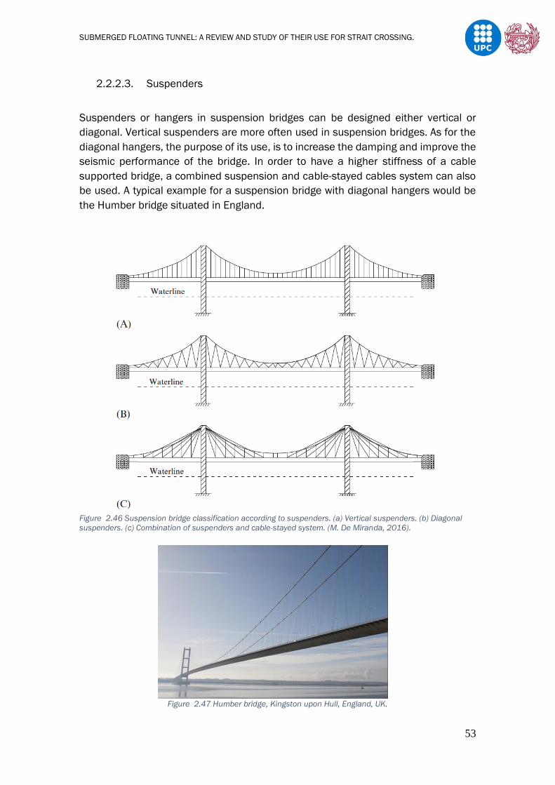
SUBMERGED FLOATING TUNNEL: A REVIEW AND STUDY OF THEIR USE FOR STRAIT CROSSING.
53
2.2.2.3. Suspenders
Suspenders or hangers in suspension bridges can be designed either vertical or
diagonal. Vertical suspenders are more often used in suspension bridges. As for the
diagonal hangers, the purpose of its use, is to increase the damping and improve the
seismic performance of the bridge. In order to have a higher stiffness of a cable
supported bridge, a combined suspension and cable-stayed cables system can also
be used. A typical example for a suspension bridge with diagonal hangers would be
the Humber bridge situated in England.
Figure 2.46 Suspension bridge classification according to suspenders. (a) Vertical suspenders. (b) Diagonal
suspenders. (c) Combination of suspenders and cable-stayed system. (M. De Miranda, 2016).
Figure 2.47 Humber bridge, Kingston upon Hull, England, UK.

SUBMERGED FLOATING TUNNEL: A REVIEW AND STUDY OF THEIR USE FOR STRAIT CROSSING.
54
2.2.2.4. Anchoring Conditions
Suspension bridges can be classified according to the anchoring conditions; they can
be either externally anchored or self-anchored, as shown in Figure 2.48 the most
common type of suspension bridges are externally anchored.
In order to do so, anchorages need to be built on both ends of the bridges to sustain
the tensile forces from the main cable. The disadvantages of Earth anchoring occur
in the difficulty of anchoring very large horizontal forces, and transmitting them to the
soil, as usually these forces are applied meters above the strong layers. The self-
anchored suspension bridge removes this last difficulty, as there is no need of
anchorages, and only vertical loads are transmitted to the soil. Inversely, construction
is more difficult, at least for long-span bridges, since the deck must be present when
the cables are installed. Therefore, the deck must be erected on temporary supports
(M. De Miranda, 2016). Usually for long-span bridges, external anchorages are more
convenient (Lin W. et al. 2017). The San Francisco Oakland Bay Bridge is a typical
example of a self-anchored suspension bridge.
Figure 2.48 Suspension bridge classification according to anchoring conditions. (a) Externally anchored
suspension bridge. (b) Self-anchored suspension bridge. (M. De Miranda, 2016).
2.2.3. Design Criteria
2.2.3.1. Geometry
A suspension bridges geometry can vary with respect to main towers and stiffening
girders, the use of one type or another, will depend on the site conditions and the
load applied.

SUBMERGED FLOATING TUNNEL: A REVIEW AND STUDY OF THEIR USE FOR STRAIT CROSSING.
55
2.2.3.1.1. Main Towers
Main towers of suspension bridges can be made out of steel or concrete structures.
Concrete structures are typically more economical, at least in areas of low seismicity
and with good soil conditions (M. De Miranda, 2016). At the top of these pylons, cable
saddles are accommodated; here practically all the load of the half bridge is
concentrated.
Figure 2.49 Typical layouts of suspension bridge towers, in size ascending order. (a) Simple frame. (b) Multiple
frame. (c) Trussed. (d) Stain lined frame. (e) Stain lined truss (M. De Miranda, 2016).
In the longitudinal direction, towers can be classified into three types; rigid, flexible,
and locking types. Flexible towers are commonly used in long-span suspension
bridges, rigid towers are used for multi span suspension bridges, to provide enough
stiffness to the bridge, and locking towers occasionally for relatively short span
suspension bridges (Okukawa et al., 1999).
Figure 2.50 Towers in suspension bridges ( Okukawa et al., 1999).

SUBMERGED FLOATING TUNNEL: A REVIEW AND STUDY OF THEIR USE FOR STRAIT CROSSING.
56
For towers in suspension bridges, the buckling due to the large compressive forces
deserves special attention. As for a SFT, if subjected with columns, buckling due to
tensile forces may happen and if subjected by tethers, foundations due to the same
forces could be displaced.
In addition, the horizontal seismic performances in the tower for bridges and in shore
connections and foundations for SFTs should be analysed.
2.2.3.1.2. Stiffening Girders or decks
The stiffening girder or deck is the surface of the bridge, it may be constructed of
concrete for small spans, but they are usually made out of steel, or a combination of
both. Usually, a railroad bed and track, asphalt concrete, or other form of pavement
for vehicle crossing covers the deck.
In suspension, deck grinders usually come in three types;
- Truss structure
- Plate girder or I-girders
- Box girder
Figure 2.51 Typical suspension bridge cross-sections. (a) Plate girder. (b) Truss girder. (c) Box girder.
(Okukawa et al., 1999).
In comparison to other decks, plate girders are very light and simple with respect to
their design, but are disadvantageous with regard to their aerodynamic behaviour as
they have a relatively low flexural stiffness and, mainly, very low torsional stiffness.
However, the use of aerodynamic fairings can improve their aerodynamic
performance and bottom bracing can improve torsional stiffness.
For modern long-span suspension bridges, trusses and box girders are more often
used.
The use of truss-stiffened girders, gives great stiffness to the whole structure while a
relatively low aerodynamic drag is maintained. However, for long spans, the weight of
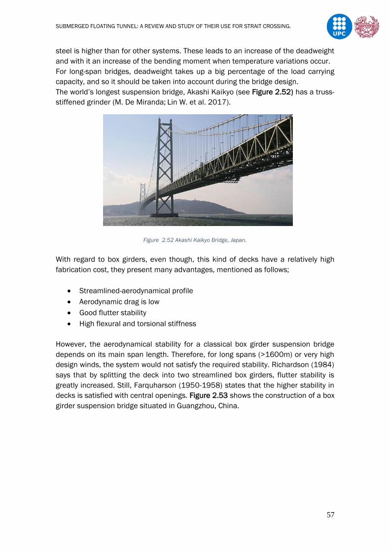
SUBMERGED FLOATING TUNNEL: A REVIEW AND STUDY OF THEIR USE FOR STRAIT CROSSING.
57
steel is higher than for other systems. These leads to an increase of the deadweight
and with it an increase of the bending moment when temperature variations occur.
For long-span bridges, deadweight takes up a big percentage of the load carrying
capacity, and so it should be taken into account during the bridge design.
The world’s longest suspension bridge, Akashi Kaikyo (see Figure 2.52) has a truss-
stiffened grinder (M. De Miranda; Lin W. et al. 2017).
Figure 2.52 Akashi Kaikyo Bridge, Japan.
With regard to box girders, even though, this kind of decks have a relatively high
fabrication cost, they present many advantages, mentioned as follows;
• Streamlined-aerodynamical profile
• Aerodynamic drag is low
• Good flutter stability
• High flexural and torsional stiffness
However, the aerodynamical stability for a classical box girder suspension bridge
depends on its main span length. Therefore, for long spans (>1600m) or very high
design winds, the system would not satisfy the required stability. Richardson (1984)
says that by splitting the deck into two streamlined box girders, flutter stability is
greatly increased. Still, Farquharson (1950-1958) states that the higher stability in
decks is satisfied with central openings. Figure 2.53 shows the construction of a box
girder suspension bridge situated in Guangzhou, China.

SUBMERGED FLOATING TUNNEL: A REVIEW AND STUDY OF THEIR USE FOR STRAIT CROSSING.
58
Figure 2.53 Second Humen Bridge, Guangzhou, China.
As in SFT, there are several cross sections for suspension bridges, but some act
better than others depending on the site conditions and the purpose of each
structure. Comparing both types of cross sections, it can be appreciated, that
suspension cross sections are much simple, in terms of materials, and SFT cross
sections are much simpler, in terms of geometry.
Both cross sections have to act against loads, aerodynamic and hydrodynamic loads,
which lead to stability problems. In SFT hydrostatic loads must be considered too.
The main problem for a SFT cross-section that does not concern a suspension bridge
is impermeability. A poor arrangement in terms of materials or a crack in the structure
due to specific events (ice, ships, submarine collision etc..) could eventually lead to
collapse due to pressurized water access.
In terms of security, for a SFT the construction of a parallel tunnel or exit towers could
be proposed, and so, in case of an accident, traffic can be redirected and emergency
exits are available. In suspension bridges, traffic access must be cut.
2.2.3.1.3. Stability of the Bridge
In a suspension bridge, the length and the stability of it depends on the sag ratio.
The sag ratio of the main cables is known as;
n = f/L eq (2.9)
Where,
f = vertical interval of the main cable in the main span known as the sag.
L = length of the span.
The sag ratio is generally taken between 1/8 and 1/12 (a generally accepted
optimum ratio is a 1/10). A bridge with a low sag ratio or said in another way, if the

SUBMERGED FLOATING TUNNEL: A REVIEW AND STUDY OF THEIR USE FOR STRAIT CROSSING.
59
main cables have a flat curve, the bridge has more vertical stability but the cable
stress is high and strong anchorages are required. On the contrary, a higher ratio or
a deeper sag, reduces cable force, but increases the height of the main towers and
makes them more susceptible to large forces and consequently the bulking
increases.
The geometrical shape of a main cable is shown in Figure 2.54.
Figure 2.54 Shape of the main cable (Lin W. et al. 2017).
Lin W. et al. (2017) demonstrates that generally the main cables deform as a
parabolic curve if it is considered that the cables and the dead weight (w) of the
stiffening grinder are uniformly distributed.
As explained before, the stability of a SFT will depend on a similar ratio, the buoyancy
ratio, where instead of relating the vertical interval with the length of the span to
stabilize the deck is vertical displacement, it relates the buoyancy of the tube with its
self-weight in order to stabilise the tube in a precise depth.
2.2.3.2. Cables
Suspension bridge cables are always made out of strong steel in parallel wires and
are galvanized, with diameters of 5,2–5,7mm.
Hangers are made with wire ropes, spiral cables, locked coil or parallel wire ropes. As
previously mentioned, always in galvanized steel and protected by sheaths and often
in high-density polyethylene. The clamps that support and anchor the hangers to the
main cables are typically made of cast steel, with bolt anchors.
The hangers are attached to the deck by hinge type anchorages next to the mooring
block, as there is maximum longitudinal rotation on the hangers, and rigid type
anchorages for the intermediate hangers.
De Miranda 2017 analyses vertical and horizontal loads produced on suspension
bridges, in order to make a good sizing of the cables. For vertical loads, she analyses
permanent and moving loads and for horizontal, she focuses on the actions of the
wind.

SUBMERGED FLOATING TUNNEL: A REVIEW AND STUDY OF THEIR USE FOR STRAIT CROSSING.
60
Figure 2.55 Cross section of the main cable in Akashi Kaikyo Bridge (De Miranda M., 2017).
2.2.3.3. Anchorages
The anchorage structure usually includes; the foundation, anchor block, bent block,
cable anchor frames, and protective housing.
These members receive through the main cables, most of the self-weight and other
loads of the bridge. In order to prevent cable force concentration inside the
anchorages, the cables are spread over a large area so that the load is distributed
evenly.
Bad dimensioned anchorages can suffer from rotary movement and slippage, and so
before anything, safety check should be confirmed.
The most often anchorage used nowadays in construction are the gravity type
anchorage systems as shown in Figure 2.56 (A) and the tunnel type anchorage as
shown in Figure 2.56 (B).
Gravity anchorages usually consist on the construction of huge concrete blocks,
which relies on the mass of the anchorage itself to resist the tension of the main
cables, that is why, before their construction a precise knowledge of the total systems
load should be given. On the other hand, the tunnel anchorage takes the tension of
the main cables into the ground. On this type of anchorage, adequate geotechnical
conditions are required.

SUBMERGED FLOATING TUNNEL: A REVIEW AND STUDY OF THEIR USE FOR STRAIT CROSSING.
61
Figure 2.56 Anchorage systems. (A) Gravity type. (B) Tunnel type. (De Miranda M., 2017).
2.2.3.4. Loads
The following loads presented as follows are based on the AASHTO specifications. In
general, this loads can be divided into two big groups: permanent loads and transient
loads (functional, fluid, seism, deformation and accidental loads). Additionally,
depending on the structure type, other forces due to creep, shrinkage, or movement
of the structure supports can take place.
1. PL (Permanent Loads):
Permanent loads include;
• Dead weight of structural elements and non-structural elements (DC).
• Dead weight of coating surface and accessories (DW).
The structural elements are those forming part of the resistance system. Inside the
non-structural elements include barriers, parapets, signals etc. In the case where no
information of the technical specifications of the precise weight is given, unitary
weights from the Table 2.14 Extracted from AASHTO specifications can be used. Dead
weight of coating surface can be estimated taking the unitary weight for a surface
thickness.

SUBMERGED FLOATING TUNNEL: A REVIEW AND STUDY OF THEIR USE FOR STRAIT CROSSING.
62
Materials Unitary weight(Kg/m3)
Aluminium 2800
Bituminous surfaces 2250
Sand, clay or compacted silt 1925
Lightweight concrete (including reinforcement) 1775
Lightweight concrete with sand (reinforcement included) 1925
Normal concrete 2400
Sand, silt or loose gravel 1600
Soft clay 1600
Ballast 2450
Steel 7850
Stone masonry 2725
Hardwood 960
Soft wood 800
Rail for road traffic 300 Kg/ml
Table 2.14 Unitary weights.
2. Fluids
Structural loads due to fluid flow (water or air) are stablished as seen in the SFT
chapter by the Bernoulli equation in combination with correction coefficients.
2.1. Wind loads
Wind speed varies with the altitude and roughness of the terrain it travels. The wind
speed increases with altitude as seen in Figure 2.57 Vg represents the limit speed,
regardless of any surface, 𝛿 is the layer thinkness and V10 is the velocity at 10m.
For bridges at heights less than 10m the V10 speed will be used, and for bigger
heights the AASHTO equation will be used;
VDZ=2,5V0(V10/VB)ln(Z/Z0) eq(2.10)
Figure 2.57 Speed profile
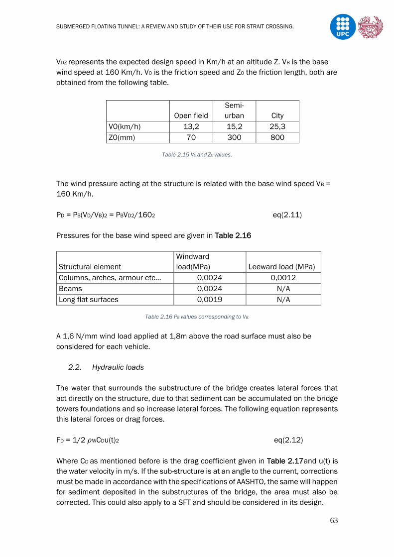
SUBMERGED FLOATING TUNNEL: A REVIEW AND STUDY OF THEIR USE FOR STRAIT CROSSING.
63
VDZ represents the expected design speed in Km/h at an altitude Z. VB is the base
wind speed at 160 Km/h. V0 is the friction speed and Z0 the friction length, both are
obtained from the following table.
Open field
Semi-
urban City
V0(km/h) 13,2 15,2 25,3
Z0(mm) 70 300 800
Table 2.15 V0 and Z0 values.
The wind pressure acting at the structure is related with the base wind speed VB =
160 Km/h.
PD = PB(VD/VB)2 = PBVD2/1602 eq(2.11)
Pressures for the base wind speed are given in Table 2.16
Structural element
Windward
load(MPa) Leeward load (MPa)
Columns, arches, armour etc… 0,0024 0,0012
Beams 0,0024 N/A
Long flat surfaces 0,0019 N/A
Table 2.16 PB values corresponding to VB.
A 1,6 N/mm wind load applied at 1,8m above the road surface must also be
considered for each vehicle.
2.2. Hydraulic loads
The water that surrounds the substructure of the bridge creates lateral forces that
act directly on the structure, due to that sediment can be accumulated on the bridge
towers foundations and so increase lateral forces. The following equation represents
this lateral forces or drag forces.
FD = 1/2 𝜌WCDu(t)2 eq(2.12)
Where CD as mentioned before is the drag coefficient given in Table 2.17and u(t) is
the water velocity in m/s. If the sub-structure is at an angle to the current, corrections
must be made in accordance with the specifications of AASHTO, the same will happen
for sediment deposited in the substructures of the bridge, the area must also be
corrected. This could also apply to a SFT and should be considered in its design.

SUBMERGED FLOATING TUNNEL: A REVIEW AND STUDY OF THEIR USE FOR STRAIT CROSSING.
64
Type Cd
Semi-circular pillar 0,7
Square pillar 1,4
Pillar with diverted flow 1,4
Table 2.17 Drag coefficient values.
3. Seismic loads
Depending on the bridge location, seismic effects can be ignored or might
influence on the bridge design. J.D. Yau et al. (2007) analyses the response of a
suspended bridge due to moving loads and seismic loads. E.S. Manrique (2004)
explain how to determine these charges by following a few steps.
a) Preliminary design (bridge type, span number, tower height, road section,
etc..).
b) Acceleration coefficient, which depend on the bridge location, this coefficient
is obtained from the seismic zoning map.
c) Importance of the bridge category. Table 2.18 Summarizes the characteristics
of the three categories of importance.
Importance
category Description
Critical bridges
After the design earthquake (475 years return period) they
must be open to all traffic and after a long earthquake (2500
year return period) must be open to emergency vehicles.
Essential bridges
After the design earthquake must be open to emergency
vehicles.
Other bridges Can be closed to be repaired after a long earthquake.
Table 2.18 Importance category.
d) From the acceleration coefficient determinate, the seismic operation of the
zone.
e) Determinate the place coefficient S. This coefficient depends on the soil
conditions.
f) Finally determine the response modification factor, which reduces seismic
forces based on the elastic analysis of the bridge system.

SUBMERGED FLOATING TUNNEL: A REVIEW AND STUDY OF THEIR USE FOR STRAIT CROSSING.
65
4. Deformation loads.
4.1. Temperature
Two types of temperatures must be considered in the structural analysis. The first
type is the uniform temperature change. This type of change in temperature affects
long and short bridges, and if the supports are restricted it will cause forces in the
stirrups of the bridge. This type of deformation is seen in Figure 2.58 a). The second
type the temperature change is a non-uniform heating or cooling gradient, this
deformation can be seen in Figure 2.58 (b).
Figure 2.58 (a) Temperature which causes dilatation. (b) Temperature which causes curvature.
Exposure to sun rays, the bridge platform will get hotter than the beams from below,
and so beams try to bend upwards. If this movement is prevented by internal
supports, internal forces will be induced. If the movement is completely free internal
stress will occur, just like the simply supported beams.
4.2. Creep and Shrinkage
The creep and shrinkage effects in the concrete produce structural stress and
fatigue. These effects are of special importance in prestressed concrete and in
superstructures with large volumes of concrete.

SUBMERGED FLOATING TUNNEL: A REVIEW AND STUDY OF THEIR USE FOR STRAIT CROSSING.
66
4.3. Settlement
Support movements can occur due to elastic deformations or inelastic deformations
of the foundations. Elastic deformations include movements that affect the response
of the bridge to other loads but permanent deformations will not be seen.
5. Accidental loads
The impact forces on a bridge during collision depend on parameters such as the
vehicle type, size, mass, and speed as well as the circumstances of the accident
(eccentricity of impact, size and shape of structures etc…). Normally the duration of
action of the maximum force in vehicle/bridge collision is very brief. Z. Kamaitis
(1997) proposes a formula to calculate the average impact force caused by vehicle.
He also proposes a formula to determinate the same force for collision of floating
debris, ice and marine traffic.
2.2.3.5. Limit States
In a suspension bridge, the same limit states are considered as in a SFT
(Serviceability, ultimate and fatigue), the difference is that possible combinations of
loads for each design limit state can be precisely known due to that fact that previous
bridges have been constructed, these values can be found on Eurocode 1 – Actions
on structures.
2.2.4. Construction methods
Classic suspension bridges always have to follow de same operation sequence (de
Miranda M., 2008);
• Construction of towers and mooring blocks.
• Formation of the supporting cables and installation of hangers.
• Installation of the girder deck.
The deck installation is done by lifting the structural elements of the deck (or panels
of the truss segments or whole segments) from the sea (or from the river or ground
depending on the environment) by a crane positioned on the cables or on the already-
erected deck.
The installation of box-girder decks in bridges starts from the centre line, where the
segments are assembled initially, and proceeds symmetrically to the towers to reduce
the risk of flutter during construction (see Figure 2.59). For bridges with trussed
decks, truss segment installation normally starts from the towers, proceed
symmetrically toward the middle of the central span, and toward the end of moorings
(see Figure 2.60).

SUBMERGED FLOATING TUNNEL: A REVIEW AND STUDY OF THEIR USE FOR STRAIT CROSSING.
67
During the erection of adjacent segments, previous lifted segments are temporarily
connected with devices designed to allow mutual rotation and to guarantee the
necessary stability due to the wind dynamic effects (de Miranda and Petrequin,
1998).
Figure 2.59 (a) Erection sequence of typical box-girder suspension bridge, by starting from mid-span in order to
minimize the risk of flutter during construction (Miranda M., 2008).

SUBMERGED FLOATING TUNNEL: A REVIEW AND STUDY OF THEIR USE FOR STRAIT CROSSING.
68
Figure 2.60 Continued. (b) Erection sequence of deck starting from pylons (Miranda M., 2008).

SUBMERGED FLOATING TUNNEL: A REVIEW AND STUDY OF THEIR USE FOR STRAIT CROSSING.
69
3. Comparison between a Suspension bridge and a
SFT in different locations.
In general, there can be several similarities noticed between the SFT and a
suspension bridge. For example, the loads are analogous; the bridge deck is
supported through vertical or inclined cables and the tunnel tube too; the gravity
loads on the cable-supported bridges are replaced by the upward residual buoyancy
in the SFTs and the role of wind being played by currents and waves actions. Of all
these similarities, the most important which has not been mentioned is that, both
infrastructures offer the possibility of crossing long distances in the fastest way. That
is why nowadays in many cases where a suspension bridge is proposed to be build,
the possibility of constructing a SFT may also appear. In this chapter, it will be seen
examples of different locations where a comparison is made between both ways of
crossing in order to obtain the most viable way.
3.1. Qiongzhou Strait, China.
Due to the demand traffic and development of civil engineering in China, several
proposals of waterway crossing have been carried out. At present Qiongzhou Strait is
frequently discussed. Qiongzhou Strait is located in the south of China, between
Leinzhou Peninsula and Hainan Island.
The Qiongzhou Strait is one of the larges three straits in China. The length is about
80 kilometres from east to west, and the widths ranges from 18 to 35,5 kilometres
from north to south. The water depth ranges from 80 to 120 m along the central axis.
On the north and south shores, scraps with a maximum height of 70 metres and a
maximum slope angle of 22º-24º are located.
The major geological structure is made out of fractures. The submarine strata are
mainly sedimentary shaped in the Tertiary and Quaternary Periods. The upper layer
is filled with sludge, sandy clay or silt, and thick-bedded clay and silty sand are
distributed on bottom layer.
Figure 3.1 Situation map.
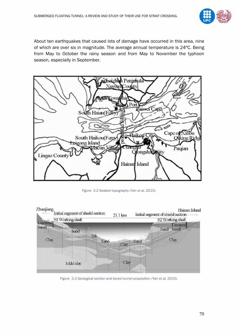
SUBMERGED FLOATING TUNNEL: A REVIEW AND STUDY OF THEIR USE FOR STRAIT CROSSING.
70
About ten earthquakes that caused lots of damage have occurred in this area, nine
of which are over six in magnitude. The average annual temperature is 24ºC. Being
from May to October the rainy season and from May to November the typhoon
season, especially in September.
Figure 3.2 Seabed topography (Yan et al. 2015).
Figure 3.3 Geological section and bored tunnel proposition (Yan et al. 2015).

SUBMERGED FLOATING TUNNEL: A REVIEW AND STUDY OF THEIR USE FOR STRAIT CROSSING.
71
According to careful investigations and evaluations, in general there are three mostly
proposed ways of crossing; the east line, the central line and the west line.
Figure 3.4 Proposed ways of crossing for Qiongzhou Strait (Yan et al. 2015).
Jiang B. et al. (2018) make a feasibility study, he proposes three ways of crossing
through the central line location, which would be resumed on Figure 4.5.
Figure 4.5. Alternatives of solution: 1) Suspension bridge. 2) SFT. 3) Submarine tunnel.
It is proposed a suspension bridge, a SFT and an underground tunnel, but we will
focus only in the comparison between the SFT and the suspension bridge made.
It is evaluated which is most viable, by focusing on previous studies done, like for
example the study made by Yan et al. (2015) which make several proposals for SFT
schemes in Qiongzhou Strait. Advantages and disadvantages with the

SUBMERGED FLOATING TUNNEL: A REVIEW AND STUDY OF THEIR USE FOR STRAIT CROSSING.
72
implementation of each way of crossing are pointed out in order to have a better view
on which is more viable.
Suspension Bridge
Advantages
• Advanced technology of design and construction
Despite the hydrological, meteorological, geological and navigation conditions in
the strait, China has rich experience in the construction of long-span bridges, such
as the Zhoushan Xihoumen Bridge and the Jiangyin Yangtze River Bridge.
In the central line location, it is feasible to construct a multiple spans bridge with
a single span of over 1000 metres. Nevertheless, the construction of the piles is
very difficult due to the conditions aforementioned; this problem can be solved by
means of updated construction technology.
• Better traffic conditions
Bridges offer better lighting, ventilation, vision, comfort and so on when the
vehicles are running on the bridge compared to tunnels.
• Easier and more economical maintenance
The bridge requires less expense on lighting and ventilation compare with
tunnels. The bridge is easier for maintenance service.
Disadvantages
• Higher expense of construction
The crossing line is around 20km. Jiang et al. says that if the bridge is designed
with single spans of around 1000m, about 20 piles and foundations will be
needed. Therefore, as the average water depth is around 50m, piers and
foundations will be difficult to construct, and the cost will be extremely high. In
order to decrease the number of piles, the span length could be increased, but
this would affect directly the bridge main towers height. He analyses the
relationship between the critical length of span (Lc) and the height of the main
tower (h) taking into account only the self-weight of the cables and different
materials.
HSS: High strength steel.
LSS: Low strength steel.
FRP: Fibre reinforced polymer.
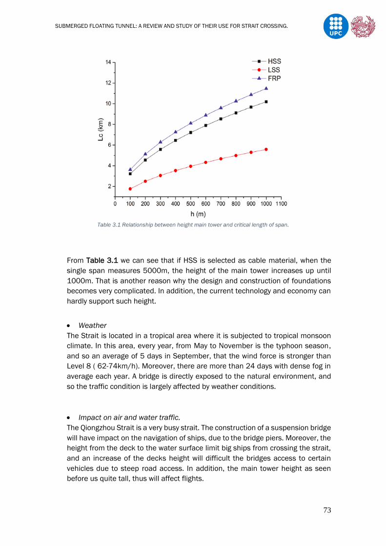
SUBMERGED FLOATING TUNNEL: A REVIEW AND STUDY OF THEIR USE FOR STRAIT CROSSING.
73
Table 3.1 Relationship between height main tower and critical length of span.
From Table 3.1 we can see that if HSS is selected as cable material, when the
single span measures 5000m, the height of the main tower increases up until
1000m. That is another reason why the design and construction of foundations
becomes very complicated. In addition, the current technology and economy can
hardly support such height.
• Weather
The Strait is located in a tropical area where it is subjected to tropical monsoon
climate. In this area, every year, from May to November is the typhoon season,
and so an average of 5 days in September, that the wind force is stronger than
Level 8 ( 62-74km/h). Moreover, there are more than 24 days with dense fog in
average each year. A bridge is directly exposed to the natural environment, and
so the traffic condition is largely affected by weather conditions.
• Impact on air and water traffic.
The Qiongzhou Strait is a very busy strait. The construction of a suspension bridge
will have impact on the navigation of ships, due to the bridge piers. Moreover, the
height from the deck to the water surface limit big ships from crossing the strait,
and an increase of the decks height will difficult the bridges access to certain
vehicles due to steep road access. In addition, the main tower height as seen
before us quite tall, thus will affect flights.

SUBMERGED FLOATING TUNNEL: A REVIEW AND STUDY OF THEIR USE FOR STRAIT CROSSING.
74
Figure 3.5 Ship traffic of one day in the Qiongzhou Strait.
• Environmental impact
The construction of bridges piles and foundations will have a direct impact to the
seabed and as a consequence to the sea flora and fauna. In addition, no matter
how elegant and high-tech a suspension bridge can be, its construction cannot
avoid interfering in some way with the surface environment.
• Pollution
While the main purpose of structural systems is to enable people to travel from
one point to another, several of them litter the route. As a result, areas around
bridges, overhang, passes often contain mounds of littler. This is why areas in and
around these bridges are often affected, influencing local life, both flora and
fauna. Furthermore, increased traffic over the bridges often results in chemical
and air pollution, thereby making it harder for those residing close by.
• Noise and vibrations
In pre-construction stage, mobilization of construction equipment will generate
noise but it will have a low impact on the environment. By contrast, a high negative
impact will be seen at the time of construction of bridge substructure especially
during pile driving, which generates high underwater and air noise levels that
affect the aquatic life. Also, during the operation and maintenance stage, there
will still be a negative noise impact to the environment.
Submerged Floating Tunnel (SFT)
Based on the geological condition of the central line and the 30m of clearance depth
between the water surface and the submerged floating tunnel proposed by Xiang et
al. 2017 in order satisfy the requirement of navigation space for big vessels and

SUBMERGED FLOATING TUNNEL: A REVIEW AND STUDY OF THEIR USE FOR STRAIT CROSSING.
75
reduce the impact from the water surface wave, Figure 3.6 represents the
longitudinal profile for the proposed SFT.
Figure 3.6 Longitudinal profile of proposed SFT.
Advantages
• Shorter distance
From Figure 3.6 we can clearly see that the distance of the submerge floating
tunnel is the shortest, for it does not need to consider the slope.
• Influence on air and water traffic
Firstly, it is obvious to see that the SFT will not have any impact to air traffic.
Besides, the gap between the SFT and the water surface where it is intended to
be build, can guarantee the security of navigation. Big ships will still be able to
cross.
• Environmental impact
The SFT will not interfere with the natural beauty of the surroundings. However,
its construction will still affect the seabed flora and fauna due to the tunnels
foundations.
• Sea current
In summer, southwest monsoon prevails and currents flow from west to east with
a high speed. In other seasons, currents flow from east to west with low speed.
This is a disadvantage to bridge, but such regular current flowing is an advantage
to submerged floating tunnel, as currents vertically act on SFT, no matter flow
from east to west or otherwise.
• Lower cost
The construction costs of a SFT, per meter length, do not increase significantly
with the length of the crossing or with the depth of the waterway, whereas the
cost of the suspension bridge will rapidly increase as the span increases.
• Noise and vibrations
As a suspension bridge, pre-construction stage mobilization of construction
equipment will generate noise and construction of foundation plus the tunnel
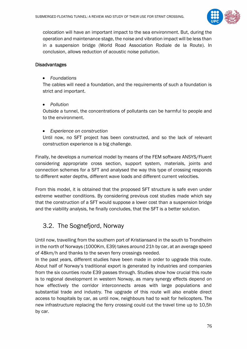
SUBMERGED FLOATING TUNNEL: A REVIEW AND STUDY OF THEIR USE FOR STRAIT CROSSING.
76
colocation will have an important impact to the sea environment. But, during the
operation and maintenance stage, the noise and vibration impact will be less than
in a suspension bridge (World Road Association Rodiale de la Route). In
conclusion, allows reduction of acoustic noise pollution.
Disadvantages
• Foundations
The cables will need a foundation, and the requirements of such a foundation is
strict and important.
• Pollution
Outside a tunnel, the concentrations of pollutants can be harmful to people and
to the environment.
• Experience on construction
Until now, no SFT project has been constructed, and so the lack of relevant
construction experience is a big challenge.
Finally, he develops a numerical model by means of the FEM software ANSYS/Fluent
considering appropriate cross section, support system, materials, joints and
connection schemes for a SFT and analysed the way this type of crossing responds
to different water depths, different wave loads and different current velocities.
From this model, it is obtained that the proposed SFT structure is safe even under
extreme weather conditions. By considering previous cost studies made which say
that the construction of a SFT would suppose a lower cost than a suspension bridge
and the viability analysis, he finally concludes, that the SFT is a better solution.
3.2. The Sognefjord, Norway
Until now, travelling from the southern port of Kristiansand in the south to Trondheim
in the north of Norways (1000Km, E39) takes around 21h by car, at an average speed
of 48km/h and thanks to the seven ferry crossings needed.
In the past years, different studies have been made in order to upgrade this route.
About half of Norway’s traditional export is generated by industries and companies
from the six counties route E39 passes through. Studies show how crucial this route
is to regional development in western Norway, as many synergy effects depend on
how effectively the corridor interconnects areas with large populations and
substantial trade and industry. The upgrade of this route will also enable direct
access to hospitals by car, as until now, neighbours had to wait for helicopters. The
new infrastructure replacing the ferry crossing could cut the travel time up to 10,5h
by car.

SUBMERGED FLOATING TUNNEL: A REVIEW AND STUDY OF THEIR USE FOR STRAIT CROSSING.
77
The Sognefjord which is about 3,7 km wide and 1300m deep, is of particular interest
as it has been used to develop and design new concepts of crossing, hitherto
unthinkable. This fjord is considered the most difficult and challenging to cross.
While the depth of the Sognefjord is extreme, the other fjords along the route are
more typically some 500-600 m deep.
The Norwegian Public Roads Administration which is responsible for the planning,
construction and operation of the national and county road networks, has initiated
several development studies in order to determine which way of crossing would be
more viable. There are three ways proposed; through a suspension bridge, a floating
bridge or a submerged floating tunnel, also a combination of these crossings have
been considered as a solution. Even though there are several ways of crossing
proposed, as on the past example, we are only going to pay attention to the
suspension bridge and the submerged floating tunnel.
Figure 3.7 Situation map of the proposed crossings.
The studies of the suspension bridge have been undertaken by the Bridge section of
the NPRA Directorate of Roads in Oslo, and have considered a suspension bridge with
a main span of 3700 metres, as the very steep slopes into the fjord, require that the
main span have the same length as the width of the fjord. There are also considered
two main towers with a total width of 33 metres and 455-metre-high.

SUBMERGED FLOATING TUNNEL: A REVIEW AND STUDY OF THEIR USE FOR STRAIT CROSSING.
78
Figure 3.8 Proposed suspension bridge for crossing the Sognefjord.
For the case of the Submerged floating tunnel, studies have been undertaken by the
consulting groups Reinertsen/Olav Olsen, Snøhetta Architects, Rambøll, Faltinsen,
Johansson, Arup and Berger ABAM. After studying several possibilities, they have
found that the most feasible way of crossing through a SFT is by means of two
separated and interconnected curved circular concrete tubes that are anchored to
floating pontoons. The tunnel will have a length of 4083 metres, and will enter
traditional rock tunnels at both sides of the fjord for connection to the main corridor.
Figure 3.9 Proposed SFT for crossing the Sognefjord.
SUBMERGED FLOATING TUNNEL: A REVIEW AND STUDY OF THEIR USE FOR STRAIT CROSSING.
79
The overall design requirements in this area are said to be satisfied, as both ways of
crossing have fulfilled width, depth and height sailing clearances of 400 metres and
70 metres, respectively. In addition, both are designed to absorb collision energies
without risk of fatal accidents for road users as well as for passengers or crew on
board the ship. Until now, the conclusions obtained are that crossing the Sognefjord
is feasible by means of either a single-span suspension bridge and submerged
floating tunnel. On the other hand, O.M.K. Iversen (2014) on his master thesis, makes
a early phase life cycle assessment considering material production, construction,
operation and maintenance over 100 years for both ways of crossing. He focuses
mainly on their environmental impact and finally concludes that the Submerged
Floating Tunnel (SFT) has the highest total emissions, with about 605 900 tonnes of
CO2-equivalents and the Suspension Bridge (SB) had emissions of 493 200 tonnes.
Yet, the Norwegian Public Roads Administration does not seem to have completed
the considerations of construction cost or technical optimisation of the designs on
the technical feasibility study.
4. Feasibility study of a SFT in the Chacao Channel.
The Chacao Channel is located in Los Lagos Region, and separates Chiloé Island from
mainland Chile. This Channel connects the Pacific Ocean and Gulf of Ancud. The new
connection will replace the current car ferry service and will reduce travel time from
45 minutes to under three minutes.
This channel has prevented the development of the Chiloe Island. Building a new
connection between mainland and Chiloe island, apart from reducing the time travel
as said before, a better social development in terms of health, services, education
and employment will be possible. In addition, this new connection will have a positive
impact on the economic development of the island. Studies show that tourism will
increase, there will be an improvement on the industrial sector and will influence on
the need of more residential infrastructure. That is why, finally it has been approved
the construction of a new suspension bridge.
The aim of this chapter is to analyse the feasibility of a SFT in this specific location
and see whether it is more viable either to construct a suspension bridge or a
Submerged Floating Tunnel.
4.1. Introduction to the Site
This channel is approximately 26 Km long from NW-SE between Chocoi and Coronel,
and varies between more than 2 Km wide in the Roca Remolinos and up to 5 Km
wide between Lenqui and Pugueñun.

SUBMERGED FLOATING TUNNEL: A REVIEW AND STUDY OF THEIR USE FOR STRAIT CROSSING.
80
As mentioned earlier, currently, the car ferry service is responsible for the crossing of
cars, offering a time of between an hour and a half and twenty minutes, depending
on the weather conditions. However, the construction of a new bridge is being
developed, this new connection will provide a less than three minutes cross by car.
Figure 4.1. shows the actual cross and Figure 4.2. shows the future cross.
Figure 4.1 Current car ferry service that crosses from Chile mainland to Chiloé.
Figure 4.2 Crossing of the new suspension bridge.
Site Conditions
The Chacao Channel is known for its extreme conditions. The presence of strong
currents, earthquakes, strong winds etc.. makes construction of infrastructure
difficult. For this reason, FHECOR Ingenieros Consultores together with COWI and
Ingeniería Cuatro, have carried out several studies in order to precisely know the site

SUBMERGED FLOATING TUNNEL: A REVIEW AND STUDY OF THEIR USE FOR STRAIT CROSSING.
81
conditions. Also, Nils Erik Miguel Lindeen de la Fuente (2012) and Herrera (2010)
study the current behaviour of the channel for carrying out a preliminary energy
resource assessment.
The results of those studies have been summarized below.
The studies focus on four principal areas which are of particular interest:
a) Seismic conditions
b) Marine conditions
c) Geotechnical conditions
d) Wind conditions
a) Seismic conditions
This channel is situated in the famous ring of fire, which is a major area in the basin
of the Pacific Ocean where many earthquakes and volcanic eruptions occur.
Figure 4.3 The Ring of Fire.
The biggest earthquake known, had its epicentre nearby the studied area and where
the suspension bridge is being constructed. For this reason, it is of extreme
importance to consider this in the design. From the seismic analysis is was found that
there were two possible origins for seismic movements: the continental fault
(subductive seism) and an hypothetic fault parallel to the axis of the channel, but yet
it has not been determined if it’s an active fault or not ; the fault of the Ancud Gulf.
The following figure shows the fault of the Gulf of Ancud.

SUBMERGED FLOATING TUNNEL: A REVIEW AND STUDY OF THEIR USE FOR STRAIT CROSSING.
82
Figure 4.4 The fault of the Gulf of Ancud.
b) Marine conditions
Sea tides
Different measurements were made in specific points of the channel in order to have
more knowledge of the Channels behaviour. The specific points analysed where;
Tique, Manao ,Carelmapu, Pihuio and finally the axis of the Chacao suspension bridge
which will be introduced lately. The following picture shows those specific points
placed in a map to understand better the results obtained.
Figure 4.5 Map situating the different specific points of interest.
Bridge axis
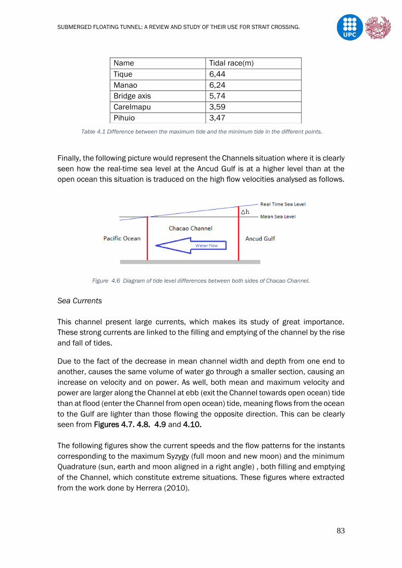
SUBMERGED FLOATING TUNNEL: A REVIEW AND STUDY OF THEIR USE FOR STRAIT CROSSING.
83
Table 4.1 Difference between the maximum tide and the minimum tide in the different points.
Finally, the following picture would represent the Channels situation where it is clearly
seen how the real-time sea level at the Ancud Gulf is at a higher level than at the
open ocean this situation is traduced on the high flow velocities analysed as follows.
Figure 4.6 Diagram of tide level differences between both sides of Chacao Channel.
Sea Currents
This channel present large currents, which makes its study of great importance.
These strong currents are linked to the filling and emptying of the channel by the rise
and fall of tides.
Due to the fact of the decrease in mean channel width and depth from one end to
another, causes the same volume of water go through a smaller section, causing an
increase on velocity and on power. As well, both mean and maximum velocity and
power are larger along the Channel at ebb (exit the Channel towards open ocean) tide
than at flood (enter the Channel from open ocean) tide, meaning flows from the ocean
to the Gulf are lighter than those flowing the opposite direction. This can be clearly
seen from Figures 4.7. 4.8. 4.9 and 4.10.
The following figures show the current speeds and the flow patterns for the instants
corresponding to the maximum Syzygy (full moon and new moon) and the minimum
Quadrature (sun, earth and moon aligned in a right angle) , both filling and emptying
of the Channel, which constitute extreme situations. These figures where extracted
from the work done by Herrera (2010).
Name Tidal race(m)
Tique 6,44
Manao 6,24
Bridge axis 5,74
Carelmapu 3,59
Pihuio 3,47

SUBMERGED FLOATING TUNNEL: A REVIEW AND STUDY OF THEIR USE FOR STRAIT CROSSING.
84
Figure 4.7 Flow pattern emptying of the Channel (Sygyzy).
Figure 4.8 Flow pattern filling of the Channel (Sygyzy).

SUBMERGED FLOATING TUNNEL: A REVIEW AND STUDY OF THEIR USE FOR STRAIT CROSSING.
85
Figure 4.9 Flow pattern emptying of the Channel (Quadrature).
Figure 4.10 Flow pattern filling of the Channel (Quadrature).

SUBMERGED FLOATING TUNNEL: A REVIEW AND STUDY OF THEIR USE FOR STRAIT CROSSING.
86
These figures clearly show the main flow in the Chacao Channel, in where the high
speed that the currents reach stands out. In condition of Syzygy, speeds close to 4 to
5m/s are reached in the area near Roca Remolinos.
Nils Erik Miguel Lindeen de la Fuente (2012) in his work pays special attention to
how water behaves in Roca Remolinos and concludes that, there, mean flow is flood
dominated at all depths in shallow areas, and ebb dominated in the deeper areas of
the same cross section. This way, recirculation reflects strong divergences and lateral
shears that translate into a relevant contribution of nonlinear terms (advection,
horizontal and vertical friction) to the momentum balance (Cáceres, Valle-Levinson,
& Atkinson, 2003).
Conclusions seen before can be better understood from Figure 4.11 , as the arrows
show in and out flow in different areas of the same cross section.
Figure 4.11 Roca Remolinos section with the inflow and the out flow from the rise and fall of tides.
Sea Waves
Waves where analysed in three parts of the channel (entrance, bridge axis and exit)
to understand more their behaviour inside and before entering or after leaving the
channel.
Waves at the bridge axis resulted having low height, being between 0-0,25m and
having periods between 3 to 4 seconds. Waves in Bahia Guapacho mostly where
about 0,5 to 2 meters with larger periods of about 15 to 16 seconds. Finally, was of
particular interest to analyse what was the extreme case that can be generated in

SUBMERGED FLOATING TUNNEL: A REVIEW AND STUDY OF THEIR USE FOR STRAIT CROSSING.
87
the Gulf of Ancud as our area of study is more exposed. So, waves in the Gulf of Ancud
resulted having heights below 1,7 meters and periods between 4 to 6 seconds. These
values have been extracted from the UK Meteorological Office Global Wave Model.
Until now, even though the Chacao Channel is situated in a high seismic zone, the
largest wave recorded which was caused by the Valdivia earthquake (22th of May,
1960) is of about 7m. This is due to the fact the area of study is relatively protected.
However, this wave generated currents up to 8 m/s.
c) Geotechnical conditions
Based on the sample visual inspection and test results, four different layers were
identified in Roca Remolinos (W. Romberg, 18 January 2006, Figure 4.12). All
elevations given herein are below the Mean Sea Level, in meters (K. Syngros et al.
2008).
1. A Tuffite (Caprock) layer exists (grey colour), about 40-meter-thick, comprising
of fine to medium sands, well to highly cemented, with low to medium silt
content.
2. Below the Tuffite layer is a layer comprising of Pleistocene Sands about 35-
meter-thick, comprising of medium sand, well to low cemented, with a few
layers of gravel. Within the same layer are sublayers with concentrated gravel
and low silt content. The layer colours vary from medium to dark grey and grey-
brown.
3. Below the Pleistocene Sand layer, there is a layer of Pliocene/Pleistocene Silt
about 30-meter-thick, comprising of hard or cemented Silt, with light brown to
yellow colour.
4. Below the Pliocene/Pleistocene Silt there is a layer of Pliocene/Pleistocene
Sands, comprising of very densely compacted, partly cemented medium
sands. Both layers form the seabed of the channel.
Figure 4.12 Roca Remolinos soil layers (W. Romberg, 2006).

SUBMERGED FLOATING TUNNEL: A REVIEW AND STUDY OF THEIR USE FOR STRAIT CROSSING.
88
d) Wind Conditions
After more than a year doing measurements of the site, the Ministerio de Obras
Públicas de Chile, said that by using the Peak Over Threshold method, base wind
speeds of up to 23,4m/s where recorded.
Also previously, FHECOR studied how wind affected perpendicular to the bridge deck
and obtained the following results.
Table 4.2 Different winds and preasures affecting the bridge deck depending on its position
4.2. The Chacao Suspension Bridge (SB)
The project consists on the construction of a long double suspension bridge with
2,754km of distance between anchor blocks. It will have three reinforced concrete
pylons, two exterior shoulders and a central (A-shape) tower on Roca Remolinos, a
point where the rock reaches the surface offering a point of support for the central
pillar; a suspended north span of 324m, two main spans (1,155m and 1,055m) and
a south approach viaduct of 140m. Least but not last, an orthotropic box girder deck
of 23.8m wide will carry four lanes of traffic.
From Figure 4.13 we can see again represented in a landscape view the SB crossing.
Also from Figure 4.14 and Figure 4.15 we can appreciate the SB proposed design
and cross section respectively.

SUBMERGED FLOATING TUNNEL: A REVIEW AND STUDY OF THEIR USE FOR STRAIT CROSSING.
89
Figure 4.13 Current suspension bridge placement.
Figure 4.14 Design of the Chacao Bridge.
Figure 4.15 Bridge cross section.

SUBMERGED FLOATING TUNNEL: A REVIEW AND STUDY OF THEIR USE FOR STRAIT CROSSING.
90
4.3. The proposed Submerged Floating Tunnel
4.3.1. Viability Study
From the distribution of the site, it is thought to be possible the design of a submerged
floating tunnel, the proposed way of crossing is seen in Figure 4.18 resulting to be a
crossing of 4 Km approximately, while the crossing of a suspension bridge is
2,754Km. A SFT will not be able to cross through the same path as the suspension
bridge, firstly because of the depth in Roca Remolinos and secondly because it is a
location where as seen before, extreme and recirculating currents are created. In
order to choose the new way of crossing it has been considered the following:
- Obviously, the depth of the Channel (Figure 4.16).
- Try to use the already constructed roads in order to avoid an increase on cost
and on environmental impact.
- Areas of Benthonic resources extraction seen in Figure 4.17.
- Areas of aqua farming activities seen in Figure 4.18. These would only be
affected during the construction of the tunnel.
From Figure 4.16 can be appreciated the depth of Roca Remolinos, which prevents
the construction of a SFT but facilitates the construction of the suspension bridge,
by offering a third support point in the middle of the channel.
Figure 4.16 Bathymetry of the Chacao Channel. (Herrera, 2010).
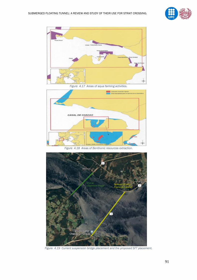
SUBMERGED FLOATING TUNNEL: A REVIEW AND STUDY OF THEIR USE FOR STRAIT CROSSING.
91
Figure 4.17 Areas of aqua farming activities.
Figure 4.18 Areas of Benthonic resources extraction.
Figure 4.19 Current suspension bridge placement and the proposed SFT placement.
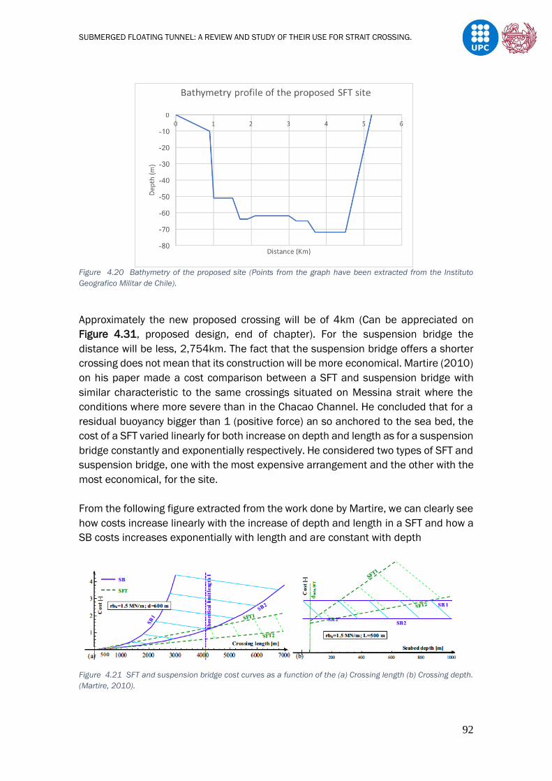
SUBMERGED FLOATING TUNNEL: A REVIEW AND STUDY OF THEIR USE FOR STRAIT CROSSING.
92
Figure 4.20 Bathymetry of the proposed site (Points from the graph have been extracted from the Instituto
Geografico Militar de Chile).
Approximately the new proposed crossing will be of 4km (Can be appreciated on
Figure 4.31, proposed design, end of chapter). For the suspension bridge the
distance will be less, 2,754km. The fact that the suspension bridge offers a shorter
crossing does not mean that its construction will be more economical. Martire (2010)
on his paper made a cost comparison between a SFT and suspension bridge with
similar characteristic to the same crossings situated on Messina strait where the
conditions where more severe than in the Chacao Channel. He concluded that for a
residual buoyancy bigger than 1 (positive force) an so anchored to the sea bed, the
cost of a SFT varied linearly for both increase on depth and length as for a suspension
bridge constantly and exponentially respectively. He considered two types of SFT and
suspension bridge, one with the most expensive arrangement and the other with the
most economical, for the site.
From the following figure extracted from the work done by Martire, we can clearly see
how costs increase linearly with the increase of depth and length in a SFT and how a
SB costs increases exponentially with length and are constant with depth
Figure 4.21 SFT and suspension bridge cost curves as a function of the (a) Crossing length (b) Crossing depth.
(Martire, 2010).

SUBMERGED FLOATING TUNNEL: A REVIEW AND STUDY OF THEIR USE FOR STRAIT CROSSING.
93
To see whether or not the construction of a SFT is viable, a comparison has been
made between our weather conditions and those of sites where a SFT design has
been proposed, to have an idea of how should be our design to be able to support all
loads and operate in the most optimal way.
Martire (2007,2010) analysed four different environmental conditions in his work.
The waves and current characteristics of the Qiandao Lake, Jintang Strait, Messina
Strait and Akashi strait, which represent mild, intermediate and severe conditions,
and Panduro J. Omar., (2013) analysed the wave and current characteristics of the
Gulf of California, which represent intermediate – severe characteristics. It is
important to notice that these parameters are analysed as the wave and current
parameters are the most important issues which define the severity of the
hydrodynamic actions. The Table 4.3 represents the different characteristics for each
site as well as the Chacao Channel in order to make the comparison between them.
Table 4.3 Comparison between locations for SFT proposals.
In the table, for the Chacao channel it has been considered 25m of clearance as
Christin Ingerslev (2010) said, currently, few if any vessels have a draught exceeding
25m. Even though, the traffic is mostly consisted on recreational traffic and ferries
destined for the strait crossing. This type of boats has small drafts and so it has been
oversized. It also has been considered the fact that there are approximately 5m
meters of difference between high and low tides. This has influenced on the SFT
buoyancy and so on its anchorage, as for a SFT subjected by pontoons it will be very
difficult to have waterproof shore connections which enables rotation due to tide
variation. So, the SFT must be anchored to the ground buoyancy by means of tethers
and gravity foundations, having a positive buoyancy. It is important to notice that by
Location
site
Condition Depth Clearance Wave
height
Wave
length
Period
wave
Current
velocity
Qiandao
Lake
Mild 30m 2.0m 1.0m 8.25m 2.3s 0.1m/s
Chacao
Channel
Mild -
Intermediate
Severe(tsunami)
70m
70m
25m
25m
1,4m
7m
20m
--
4s
--
2.5m/s
8m/s
Akashi
Strait
Severe 80m 30m 9.4m -- -- 4m/s
Jintang
Strait
Intermediate 100m 25m 5.8m 76.5m 7.0s 4.1m/s
Quiongzhou
strait
Intermediate 150m 30m 5m -- -- 3.5m/s
Messina
Strait
Severe 200m 30m 13,5m 200m 11.5s 3.45m/s
Gulf of
California
Intermediate-
Severe
213m 25m 9.5m 99.8m 8.0s 2.9m/s

SUBMERGED FLOATING TUNNEL: A REVIEW AND STUDY OF THEIR USE FOR STRAIT CROSSING.
94
having the SFT anchored to the ground, when high tides, the SFT clearance will be of
25m and when low tides the clearance will be reduced to approximately 20m.
So, from Table 4.3 we can see that the characteristics of the natural conditions of
the crossing are among the mild (Qiandao Lake) and the intermediate (Jintang Strait).
The wave conditions are similar to the Qindao Lake presenting a little variation.
Moreover, the current velocity in the Channel even under extreme conditions is minor
to the intermediate condition crossing but higher than the mild condition crossing.
Hence, the natural conditions in the Chacao Channel at the chosen section are
acceptable for the placement of a Submerge Floating Tunnel.
On the other hand, even though for natural conditions it is acceptable, it is of extreme
importance to be aware of the high seismicity and of the probability of a tsunami to
take place. As seen in the table, it is not so the height of the wave produced, but the
currents produced that may concern the placement of the SFT, as the site is relatively
protected. The values shown in the table are from a wave created by the Valdivia
earthquake (22th of May, 1960), this wave caused huge damage in the city of
Maullín, situated at the entrance of the channel and so far, it is the largest we have
recorded in this zone.
4.3.2. SFT Proposed Design
The design chosen is based on a comparison of our case with other similar locations
where different designs have been proposed and see which one fits better. If more
precise data could be available it would be possible to optimize the design.
4.3.2.1. Cross Section
Locations such as the Akashi strait (severe conditions), the Gulf of California
(intermediate – severe conditions) and the Quiongzhou Strait (intermediate) have
been considered and compared to our case. Our case normally consists of mild
conditions but there is the possibility of tsunamis occurring and causing severe
conditions that is why the project must be overestimate and locations with severe
conditions have been considered. In these locations Martire (2010), Panduro J.
Omar., (2013) and B. Jiang et al. (2018) proposed different cross sections
respectively.

SUBMERGED FLOATING TUNNEL: A REVIEW AND STUDY OF THEIR USE FOR STRAIT CROSSING.
95
a)
Figure 4.22 Martire 2010 cross section proposal for Akashi Strait.
b)
Figure 4.23 Panduro J. Omar., (2013) cross section proposal for the Gulf of California.
c)
Figure 4.24 Jiang et al. (2018) cross section proposal for Quiongzhou Strait.
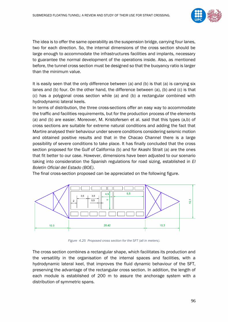
SUBMERGED FLOATING TUNNEL: A REVIEW AND STUDY OF THEIR USE FOR STRAIT CROSSING.
96
The idea is to offer the same operability as the suspension bridge, carrying four lanes,
two for each direction. So, the internal dimensions of the cross section should be
large enough to accommodate the infrastructures facilities and implants, necessary
to guarantee the normal development of the operations inside. Also, as mentioned
before, the tunnel cross section must be designed so that the buoyancy ratio is larger
than the minimum value.
It is easily seen that the only difference between (a) and (b) is that (a) is carrying six
lanes and (b) four. On the other hand, the difference between (a), (b) and (c) is that
(c) has a polygonal cross section while (a) and (b) a rectangular combined with
hydrodynamic lateral keels.
In terms of distribution, the three cross-sections offer an easy way to accommodate
the traffic and facilities requirements, but for the production process of the elements
(a) and (b) are easier. Moreover, M. Kristofersen et al. said that this types (a,b) of
cross sections are suitable for extreme natural conditions and adding the fact that
Martire analysed their behaviour under severe conditions considering seismic motion
and obtained positive results and that in the Chacao Channel there is a large
possibility of severe conditions to take place. It has finally concluded that the cross
section proposed for the Gulf of California (b) and for Akashi Strait (a) are the ones
that fit better to our case. However, dimensions have been adjusted to our scenario
taking into consideration the Spanish regulations for road sizing, established in El
Boletin Oficial del Estado (BOE).
The final cross-section proposed can be appreciated on the following figure.
Figure 4.25 Proposed cross section for the SFT (all in meters).
The cross section combines a rectangular shape, which facilitates its production and
the versatility in the organisation of the internal spaces and facilities, with a
hydrodynamic lateral keel, that improves the fluid dynamic behaviour of the SFT,
preserving the advantage of the rectangular cross section. In addition, the length of
each module is established of 200 m to assure the anchorage system with a
distribution of symmetric spans.

SUBMERGED FLOATING TUNNEL: A REVIEW AND STUDY OF THEIR USE FOR STRAIT CROSSING.
97
4.3.2.2. Joints
Inter-modular Connections
The connection between the elements is fundamental for the SFT behaviour.
Therefore, there will be flexible connections between the elements allowing a
minimum flexion and extension between modules. In our case, it is proposed the
normal practice for immersed tunnels, which consist on attaching and sealing each
element by means of the Gina gasket and Omega seal. The combination of both not
only allows for sealing but also for transfer of hydrostatic loads and movements
between elements. The normal practice adopted is described below, following the
Trelleborg Baker instructions, as they are expert suppliers on this type of joints.
To ensure that the tunnel elements are watertight and capable floating, elements are
temporary provided with bulkheads at both ends. On one end of each tunnel element,
an endless Gina gasket is mounted. Once on site, the tunnel element is pulled firmly
up against the preceding floating element with hydraulic jacks.
When the gasket has full contact around the total section of the adjacent element,
the water between bulkheads is pumped, normally inside the tunnel. Due to the
different pressure between bulkheads and the hydrostatic pressure on the outside of
the tunnel, the GINA profile compresses and seals the joint.
The Omega seal is then clamped across the joint on the inside faces of the two
elements. In general, after the approval of the pressure test between Gina and
Omega, bulkheads are removed. The following figure shows an outline of the steps
previously described.
Figure 4.26 J Construction steps of the inter-modular joints (Trelleborg Baker).
Figure 4.27 Details of the inter-modular joints. (a) Before installing contact (b) After installation of Omega.
(Bistoon Baspar LTD)

SUBMERGED FLOATING TUNNEL: A REVIEW AND STUDY OF THEIR USE FOR STRAIT CROSSING.
98
Shore Connections
Due to the high seismicity of the site and considering the great length of the SFT
proposed, the shore connections must allow free rotation and axial displacement as
the displacement and the affectations produced by natural events must be
considered as local issues. The proposed joint adopted in our design was the one
proposed in the Qiandao Lake, China (Mazzolani et al. 2007). This shore connection
allows the structure to expand in presence of thermal variations and acts well against
water tightening. The general concept is based on separating the waterproof and
mechanical functions of the device (Panduro J. Omar., 2013).
Figure 4.28 ptual design for the shore connection (Mazzolani et al., 2007).
4.3.2.3. Anchorage System
The anchorage system will consist of steel cables subjected to gravity foundations as
seen in Figure 4.29 It is important to see that the distance between the foundations
and the SFT modules will vary depending on the depth of the crossing, being the
distance shorter in shallow depths and so having stiffer cables and bigger distances
in deeper parts of the crossing. Martire’s results show that, anchoring systems gets
considerably more involved in carrying the external loads as the crossing length
increases due to the reduction of tunnel bending stiffness, so that , the critical point
in larger crossings is generally ensuring enough strength to the anchorages and/or
reducing their maximum axial forces induced by hydrodynamic loads. In our case, it
is considered a long cross and so, this has been considered.

SUBMERGED FLOATING TUNNEL: A REVIEW AND STUDY OF THEIR USE FOR STRAIT CROSSING.
99
Figure 4.29 Transversal anchorage configurations.
Having this type of cable configuration brings relevant advantages to our design in
terms of maximum displacement and reduce maximum moments, if two cable
systems are provided per module as seen in Figure 2.26. It is also seen that
increasing the number of cables more than two per tunnel module produces no
relevant advantages in terms of maximum displacements (Martire, 2010). As Hong
Y. et al. (2010) concluded the tether angle must be larger than 30º. As in similar
cases such as in the Qiongzhou strait or in California Gulf, the tether angle employed
has been of 60º and 45º, the same angles have been considered.
Finally, four anchorage systems have been considered along the longitudinal axis as
seen in Figure 4.30 this means that for each 200m module there will be a total of
sixteen cables and between each anchorage system a distance of 50m.
Figure 4.30 Longitudinal anchorage configuration.
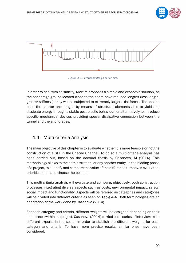
SUBMERGED FLOATING TUNNEL: A REVIEW AND STUDY OF THEIR USE FOR STRAIT CROSSING.
100
Figure 4.31 Proposed design set on site.
In order to deal with seismicity, Martire proposes a simple and economic solution, as
the anchorage groups located close to the shore have reduced lengths (less length,
greater stiffness), they will be subjected to extremely larger axial forces. The idea to
build the shorter anchorages by means of structural elements able to yield and
dissipate energy through a stable post-elastic behaviour, or alternatively to introduce
specific mechanical devices providing special dissipative connection between the
tunnel and the anchorages.
4.4. Multi-criteria Analysis
The main objective of this chapter is to evaluate whether it is more feasible or not the
construction of a SFT in the Chacao Channel. To do so a multi-criteria analysis has
been carried out, based on the doctoral thesis by Casanova, M (2014). This
methodology allows to the administration, or any another entity, in the bidding phase
of a project, to quantify and compare the value of the different alternatives evaluated,
prioritize them and choose the best one.
This multi-criteria analysis will evaluate and compare, objectively, both construction
processes integrating diverse aspects such as costs, environmental impact, safety,
social impact and functionality. Aspects will be referred as categories and categories
will be divided into different criteria as seen on Table 4.4. Both terminologies are an
adaptation of the work done by Casanova (2014).
For each category and criteria, different weights will be assigned depending on their
importance within the project. Casanova (2014) carried out a series of interviews with
different experts in the sector in order to stablish the different weights for each
category and criteria. To have more precise results, similar ones have been
considered.
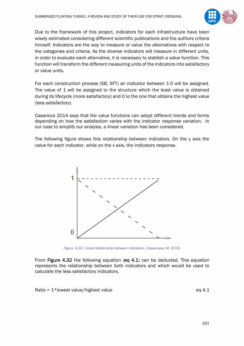
SUBMERGED FLOATING TUNNEL: A REVIEW AND STUDY OF THEIR USE FOR STRAIT CROSSING.
101
Due to the framework of this project, indicators for each infrastructure have been
wisely estimated considering different scientific publications and the authors criteria
himself. Indicators are the way to measure or value the alternatives with respect to
the categories and criteria. As the diverse indicators will measure in different units,
in order to evaluate each alternative, it is necessary to stablish a value function. This
function will transform the different measuring units of the indicators into satisfactory
or value units.
For each construction process (SB, SFT) an indicator between 1-0 will be assigned.
The value of 1 will be assigned to the structure which the least value is obtained
during its lifecycle (more satisfactory) and 0 to the one that obtains the highest value
(less satisfactory).
Casanova 2014 says that the value functions can adopt different trends and forms
depending on how the satisfaction varies with the indicator response variation. In
our case to simplify our analysis, a linear variation has been considered.
The following figure shows this relationship between indicators. On the y axis the
value for each indicator, while on the x axis, the indicators response.
Figure 4.32 Lineal relationship between indicators. (Casanovas, M. 2014)
From Figure 4.32 the following equation (eq 4.1) can be deducted. This equation
represents the relationship between both indicators and which would be used to
calculate the less satisfactory indicators.
Ratio = 1*lowest value/highest value eq 4.1

SUBMERGED FLOATING TUNNEL: A REVIEW AND STUDY OF THEIR USE FOR STRAIT CROSSING.
102
Table 4.4 Impact table for the construction process evaluation.
4.4.1. Indicator Estimation
Construction cost
Given that there are no experiences in the construction of tunnels in the marine
environment and that there are no records of costs for already constructed immersed
tunnels, the price will be estimated from a land-based tunnel and applying a factor to
take into account that it is an infrastructure to be built in the sea. In order to obtain
this factor, it is necessary to study the relationship between a terrestrial structure
and its counterpart built in the sea. One case that is currently common is the
construction of wind turbines on land and at sea and, therefore, it has been
Global
weights
(%)
Category
Criteria
weights
(%)
Criteria
21.3 Economic
Impact
29.5 Construction Costs
33.2 Maintenance Costs
37.3 Durability
20.1 Environmental
Impact
19.1 Landscape Impact
19.5 Fauna and Flora Impact
20.3 Sea water Impact
20 Air Impact
21.1 Noise Impact
19.1 Social
31.8 Execution Time
36.5 Travel Affectation
31,7
Inconvenience to
neighbours during
construction
20.5 Safety
40.2 Against Earthquake
29.4 Against Tsunami
30.4 Against Collision
19 Functionality
40.2 Cross section
13.5 Extension Possibility
46.3 Connectivity to existing
road network

SUBMERGED FLOATING TUNNEL: A REVIEW AND STUDY OF THEIR USE FOR STRAIT CROSSING.
103
considered that the relationship between their costs gives us an approximate idea of
the relationship between the cost of a conventional tunnel and one at sea.
Before calculating the sea factor, we must see if the sections of both tunnels
coincide, since the price will not only vary with the length, but also with the section. If
they don’t coincide, a correction factor between the different areas will have to be
stablished.
The cost of the conventional tunnel constructed in Barcelona for the new AVE line,
using an EPB type TBM, with 11 m external diameter, was about 200M euros with a
length of 5Km and a section of 85m2 with approximately 40.000 euros per m.
At first glance, it can be appreciated that our section is larger, so it will be necessary
to calculate a corrector.
After calculating our section obtaining a value of 200m2, the correction factor will be
200/85=2,35.
The construction of an offshore wind tower costs approximately 11M euros and the
construction of a inshore wind tower cost approximately 3,5M of euros; this prices
have been extracted from the work done by Moraleda M. (2013) and Hoyo L. (2018)
respectively. Finally, the sea factor obtained is 3.14.
Multiplying the approximated cost per m of the construction of the AVE by our total
distance (4000m) and by both factors, we obtain that the price of the SFT is about
1125M of euros.
Knowing that the Chacao bridge cost will be approximately 900M of euros we can
now calculate the indicator. For the SB = 900/900 = 1 and for the SFT = 900/1125
= 0.8
Construction SB SFT
Indicator 1 0.8 Table 4.5 Construction cost indicator.
Maintenance cost
The usual maintenance costs related to tunnels in general, such as lighting,
ventilation, traffic control, drainage, interior cleaning etc... which are expected to be
low, usually in tunnels is estimated to be an annual 1,5% of the total cost (Egil
Lundebrekke, 2014). On the other hand, as bridge is directly exposed to the natural
environment there are additional costs. Maintenance task such as dehumidification,
protection against scour, improvement on paintings are extra costs compared to a
tunnels maintenance and adding the fact that the Chacao Channel is situated in a
place with a lot of humidity, strong winds and where it rains a lot, maintenance costs
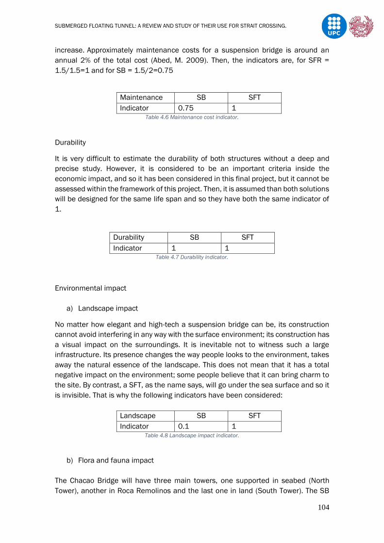
SUBMERGED FLOATING TUNNEL: A REVIEW AND STUDY OF THEIR USE FOR STRAIT CROSSING.
104
increase. Approximately maintenance costs for a suspension bridge is around an
annual 2% of the total cost (Abed, M. 2009). Then, the indicators are, for SFR =
1.5/1.5=1 and for SB = 1.5/2=0.75
Maintenance SB SFT
Indicator 0.75 1 Table 4.6 Maintenance cost indicator.
Durability
It is very difficult to estimate the durability of both structures without a deep and
precise study. However, it is considered to be an important criteria inside the
economic impact, and so it has been considered in this final project, but it cannot be
assessed within the framework of this project. Then, it is assumed than both solutions
will be designed for the same life span and so they have both the same indicator of
1.
Durability SB SFT
Indicator 1 1 Table 4.7 Durability indicator.
Environmental impact
a) Landscape impact
No matter how elegant and high-tech a suspension bridge can be, its construction
cannot avoid interfering in any way with the surface environment; its construction has
a visual impact on the surroundings. It is inevitable not to witness such a large
infrastructure. Its presence changes the way people looks to the environment, takes
away the natural essence of the landscape. This does not mean that it has a total
negative impact on the environment; some people believe that it can bring charm to
the site. By contrast, a SFT, as the name says, will go under the sea surface and so it
is invisible. That is why the following indicators have been considered:
Landscape SB SFT
Indicator 0.1 1 Table 4.8 Landscape impact indicator.
b) Flora and fauna impact
The Chacao Bridge will have three main towers, one supported in seabed (North
Tower), another in Roca Remolinos and the last one in land (South Tower). The SB
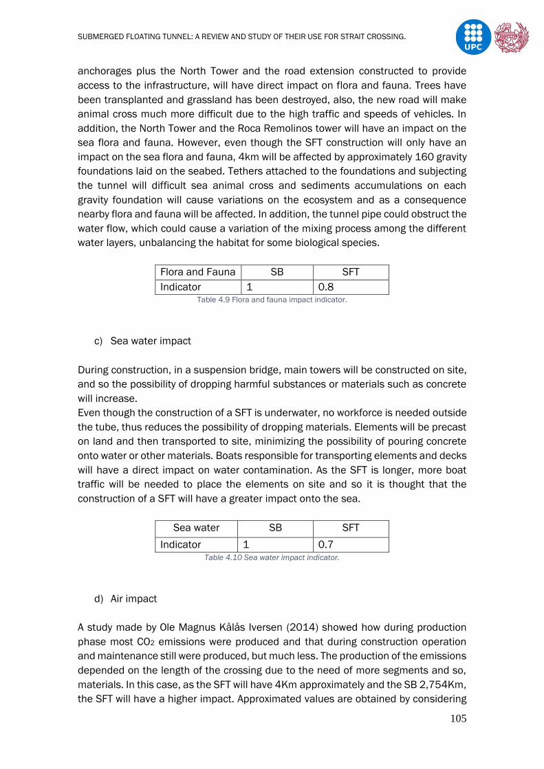
SUBMERGED FLOATING TUNNEL: A REVIEW AND STUDY OF THEIR USE FOR STRAIT CROSSING.
105
anchorages plus the North Tower and the road extension constructed to provide
access to the infrastructure, will have direct impact on flora and fauna. Trees have
been transplanted and grassland has been destroyed, also, the new road will make
animal cross much more difficult due to the high traffic and speeds of vehicles. In
addition, the North Tower and the Roca Remolinos tower will have an impact on the
sea flora and fauna. However, even though the SFT construction will only have an
impact on the sea flora and fauna, 4km will be affected by approximately 160 gravity
foundations laid on the seabed. Tethers attached to the foundations and subjecting
the tunnel will difficult sea animal cross and sediments accumulations on each
gravity foundation will cause variations on the ecosystem and as a consequence
nearby flora and fauna will be affected. In addition, the tunnel pipe could obstruct the
water flow, which could cause a variation of the mixing process among the different
water layers, unbalancing the habitat for some biological species.
Flora and Fauna SB SFT
Indicator 1 0.8 Table 4.9 Flora and fauna impact indicator.
c) Sea water impact
During construction, in a suspension bridge, main towers will be constructed on site,
and so the possibility of dropping harmful substances or materials such as concrete
will increase.
Even though the construction of a SFT is underwater, no workforce is needed outside
the tube, thus reduces the possibility of dropping materials. Elements will be precast
on land and then transported to site, minimizing the possibility of pouring concrete
onto water or other materials. Boats responsible for transporting elements and decks
will have a direct impact on water contamination. As the SFT is longer, more boat
traffic will be needed to place the elements on site and so it is thought that the
construction of a SFT will have a greater impact onto the sea.
Sea water SB SFT
Indicator 1 0.7 Table 4.10 Sea water impact indicator.
d) Air impact
A study made by Ole Magnus Kålås Iversen (2014) showed how during production
phase most CO2 emissions were produced and that during construction operation
and maintenance still were produced, but much less. The production of the emissions
depended on the length of the crossing due to the need of more segments and so,
materials. In this case, as the SFT will have 4Km approximately and the SB 2,754Km,
the SFT will have a higher impact. Approximated values are obtained by considering

SUBMERGED FLOATING TUNNEL: A REVIEW AND STUDY OF THEIR USE FOR STRAIT CROSSING.
106
the results from Iversen study and correlating them to our case. Then, the indicators
are, for SB= 367,092/367,092=1 and for SFT = 367,092/605,895=0.6
SB SFT
Production 348,671 571,361
Construction 10,789 18,311
Operation and Maintenance 7,632 16,223
Total 367,092 589,672
Table 4.11 Tonnes of CO2-equivalents
Table 4.12 Air impact indicator
e) Noise impact
As mentioned earlier in Chapter 3, in a SFT as in a SB, the mobilization of construction
equipment in the pre-construction stage will generate noise and the construction of
the foundations, but in addition to the placement of the tunnel, it will have a major
impact on the marine environment. By contrast, during operation and maintenance
stage, the impact of noise and vibration will be less than on a suspension bridge
(World Road Association Rodiale de la Route, 2018) and considering that actually
there is a huge traffic crossing the strait. The following indicators have been
considered:
Table 4.13 Noise impact indicator
Social impact
a) Execution time
The bridge was intended to be built in 6 years and the SFT is estimated to be built in
8 years, A comparison between the Messina Strait (3300m) has been made which
was estimated to be 7 years, so approximately 2 years/km. Then, the indicators are,
for SB = 6/6=1 and for SFT =6/8=0.75
Air SB SFT
Indicator 1 0.6
Noise SB SFT
Indicator 0.3 1

SUBMERGED FLOATING TUNNEL: A REVIEW AND STUDY OF THEIR USE FOR STRAIT CROSSING.
107
Table 4.14 Execution time indicator.
b) Travel affectation
To calculate an approximate indicator, it has been considered two random points in
order to evaluate the cross time. It is clearly seen, that an increase of distance will
suppose an indicator variation as the difference between crossings is of about 5,5
minutes. The velocity considered for the Chacao Bridge crossing was 100Km/h
(Dirección General de Concesiones del Ministerio de Obras Públicas de Chile)
established and for the SFT 80km/h, due to the long and claustrophobic cross which
cause ease to get distracted. Having higher speeds would increase probability of
accidents and as a consequence its impact, as a reference Spanish tunnels have
been considered such as the Viella tunnel in Lerida (Barios, J., 2005). Also, it has
been considered that the SFT alternative will cross through Pargua and so velocity
will have to be reduced to 50Km/h before accessing the tunnel. Then, the indicators
are, for SB = 9/9=1 and for SFT =9/14.5=0.62
Figure 4.33 Different cross times for the different infrastructures.
Table 4.15 Travel affectation indicator.
Time SB SFT
Indicator 1 0.75
Travel SB SFT
Indicator 1 0.62
Pargue

SUBMERGED FLOATING TUNNEL: A REVIEW AND STUDY OF THEIR USE FOR STRAIT CROSSING.
108
c) Inconvenience to neighbours during construction
During the tunnel construction, all the material will have to be transported by truck
through Pargua, which will cause great inconveniences, such as noise, traffic, close
of streets and so more withholdings. By contrast, the bridge construction is far apart
from cities.
Table 4.16 Neighbours inconvenience indicator.
Safety
a) Against earthquake
The structure of the SFT is much more flexible than the bridge structure. The idea to
build the shorter anchorages by means of structural elements able to yield and
dissipate energy through a stable post-elastic behaviour and the combination of Gina
gasket and Omega seal between elements will allow a minimum bending and
extension between modules. Even though, a suspension bridge is considered one of
the most flexible bridges, it has still considered that a SFT has a better behaviour.
Table 4.17 Earthquake indicator.
b) Against tsunami
The design of this SFT is considering currents up to 4,5m/s, the fact that the largest
tsunami recorded until now created currents up to 8m/s could create loads, which
SFT anchors would not be able to support and would eventually collapse. Waves of
7m though, do not suppose any inconvenience, as similar designs are able to support
constant bigger waves. For FHECOR Ingenieros Consultores (2002), this tsunami
does not represent to be a big problem to the security of the bridge structure.
Table 4.18 Tsunami indicator.
Inconvenience SB SFT
Indicator 1 0.3
Inconveniences SB SFT
Indicator 0.3 1
Tsunami SB SFT
Indicator 1 0.6

SUBMERGED FLOATING TUNNEL: A REVIEW AND STUDY OF THEIR USE FOR STRAIT CROSSING.
109
c) Against collision
It is thought to be more probable that the proposed SFT collapses by collision than
the Chacao Bridge. There are more possibilities of things that can collide the SFT than
the bridge, and so probability increases. Firstly, the collision of an anchor dragged by
a ship it is thought to be the most probable thing to collide. Secondly, the presence
of whales in these zones are very common and so the collision of a disoriented whale
it is believed to be possible. Finally, but least probable, the collision of a sinking ship.
On the other hand, a ship collision with the main towers suspended on the seabed’s
channel, it is thought to be very improbable as the tower which is thought to be more
likely to be collided, is only accessible during high tides. During small tides, the main
tower is protected by what stands out from Roca Remolinos.
Table 4.19 Collision indicator.
Functionality
a) Cross section
Even though a rectangular cross section is used for the proposed SFT, which would
be one of the most effective in terms of functionality within tunnel cross sections;
still, height would be a restrictive characteristic of it (In the European Union, vehicles
with a gauge greater than 4 to 4,3m are not allowed in tunnels). By contrast, a bridge
would obviously not be affected as vehicles circulate in open air, more space will be
offered for facility distribution and will be able to guarantee access to every vehicle
(weight restriction). However, el Ministerio de Transportes y Telecomunicaciones de
Chile in his last resolution of the articles 56º and 57º of the law Nº 18.696
(http://bcn.cl/1vg3n) establishes 4,2m as the maximum height permitted and for
special vehicles 4,3m, such as trucks destined to the transport of vehicles. Steer
Davies Gleave consultancy in 2002 studied the increase of traffic over time and
estimated the future demand of the new suspension bridge. Considering his
estimation for 2018, a total of 6762 vehicles crossed the channel, being 1130 heavy
vehicles, a 16,7% of the total traffic. If we consider that five percent of this traffic
exceed the tunnels maximum height stablished in 4,3m, 56,5 vehicles will have not
been able to cross through the SFT, 0,83% of the total traffic and would have to use
ferries to cross. (In this case, the less has considered being the worst). Then, the
indicators are, for SB = 6762/6762=1 and for SFT =6756 /6762=0.99.
Table 4.20 Cross section indicator.
Collision SB SFT
Indicator 1 0.8
Cross section SB SFT
Indicator 1 0.99
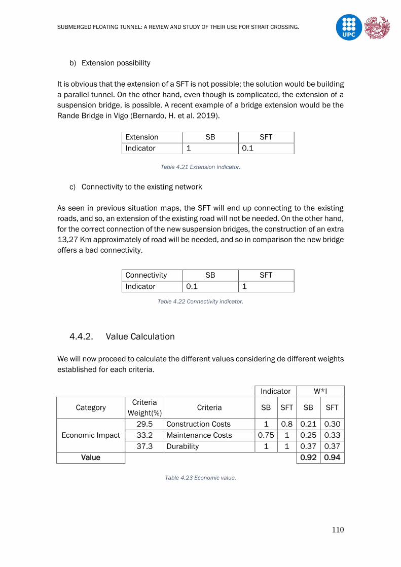
SUBMERGED FLOATING TUNNEL: A REVIEW AND STUDY OF THEIR USE FOR STRAIT CROSSING.
110
b) Extension possibility
It is obvious that the extension of a SFT is not possible; the solution would be building
a parallel tunnel. On the other hand, even though is complicated, the extension of a
suspension bridge, is possible. A recent example of a bridge extension would be the
Rande Bridge in Vigo (Bernardo, H. et al. 2019).
Table 4.21 Extension indicator.
c) Connectivity to the existing network
As seen in previous situation maps, the SFT will end up connecting to the existing
roads, and so, an extension of the existing road will not be needed. On the other hand,
for the correct connection of the new suspension bridges, the construction of an extra
13,27 Km approximately of road will be needed, and so in comparison the new bridge
offers a bad connectivity.
Table 4.22 Connectivity indicator.
4.4.2. Value Calculation
We will now proceed to calculate the different values considering de different weights
established for each criteria.
Indicator W*I
Category Criteria
Weight(%) Criteria SB SFT SB SFT
Economic Impact
29.5 Construction Costs 1 0.8 0.21 0.30
33.2 Maintenance Costs 0.75 1 0.25 0.33
37.3 Durability 1 1 0.37 0.37
Value 0.92 0.94
Table 4.23 Economic value.
Extension SB SFT
Indicator 1 0.1
Connectivity SB SFT
Indicator 0.1 1

SUBMERGED FLOATING TUNNEL: A REVIEW AND STUDY OF THEIR USE FOR STRAIT CROSSING.
111
From the calculated results, we can appreciate that the SB alternative is more
unfavourable with respect to the economic impact. In addition, it is also seen how the
SFT cost does not vary exponentially with length. Durability should be more deeply
investigated in order to have more precise conclusions.
Table 4.24 Environmental value.
From the results obtained it can be seen that the SFT will have a less environmental
impact, considering the fact that a noise impact has more weight than a sea water or
fauna and flora impact. Noise will be a part of the whole lifecycle for both
infrastructures. On the other hand, it is thought that seawater, flora, and fauna will
only be affected during the construction of both, as once infrastructures are on its
operation phase, the impact will be already caused. In addition, landscape impact it
is thought to have the least weight, as a view impact will only affect the natural
concept of the site.
Indicator W*I
Category
Criteria
Weight
(%)
Criteria SB SFT SB SFT
Social Impact
31.8 Execution Time 1 0.75 0.32 0.24
36.5 Travel Affectation 1 0.62 0.37 0.23
31.7
Inconvenience to
neighbours during
construction
1 0.3 0.32 0.10
Value 1.00 0.53
Table 4.25 Social value.
From the table can be appreciated how the construction of the Chacao bridge will
more satisfying value. Less time for its construction will be needed as the crossing is
Indicator W*I
Category
Criteria
Weight
(%)
Criteria SB SFT SB SFT
Environmental
Impact
19.1 Landscape Impact 0,1 1 0.02 0.19
19.5 Fauna and Flora Impact 1 0.8 0.20 0.16
20.3 Sea water Impact 1 0.6 0.20 0.12
20 Air Impact 1 0.6 0.20 0.12
21.1 Noise Impact 0.3 1 0.06 0.21
Value 0.68 0.80

SUBMERGED FLOATING TUNNEL: A REVIEW AND STUDY OF THEIR USE FOR STRAIT CROSSING.
112
shorter and there is more experience on the construction of bridges. Its less lower
time of construction means its access will be guaranteed before. In addition,
disturbances on the surroundings will last less. As seen in the table and analysed
previously, the bridge will provide a quicker crossing and so vehicles will be able to
get to their destinations before, even though there is only a difference of 5,5minutes
which is not much depending on the drivers destination. Finally, fewer
inconveniences to neighbours will be caused, as its construction will take place far
apart from the nearest village.
Indicator W*I
Category Criteria
Weight (%) Criteria SB SFT SB SFT
Safety
40.2 Against Earthquake 0.3 1 0.16 0.40
29.4 Against Tsunami 1 0.6 0.29 0.18
30.4 Against Collision 1 0.8 0.30 0.24
Value 0.72 0.82
Table 4.26 Safety.
From the calculated results, we can appreciate that the SB alternative is more
unfavourable with respect to the safety of the infrastructures. Weights have been
stablished considering the probability of occurrence and affectation. It can be
appreciated, it has been considered a much bigger weight for safety against
earthquakes as it is more probable for an infrastructure to fail due to the high
seismicity of the zone, and SFT appears to have a much better response against
them. It has also been considered the probability of failing due to collision and
tsunamis, but its occurrence and affectations are considered minor. It is thought that
the SB will be less affected by both as explained before.
Table 4.27 Functionality.
Finally, it can be appreciated from Table 4.27 that the proposed SFT will be a much
more favourable alternative in comparison with the SB in terms of functionality.
Indicator W*I
Category Criteria
Weight (%) Criteria SB SFT SB SFT
Functionality
40.2 Cross section 1 0,95 0.40 0.38
13.5 Extension Possibility 1 0,1 0.14 0.01
46.3 Connectivity to existing
road network 0.1 1 0.05 0.46
Value 0.58 0.86

SUBMERGED FLOATING TUNNEL: A REVIEW AND STUDY OF THEIR USE FOR STRAIT CROSSING.
113
Connectivity to existing roads it is thought to be of great importance inside the
functionality of these infrastructures. The need of new roads will have a direct impact
on the environment, on the construction cost and on the execution time of the project.
Therefore, taking advantage of the existing roads reduces these impacts.
The infrastructure cross section has also thought to be of great importance in terms
of functionality. Depending on the section considered, the arrangement of facilities
can be much more difficult and could determine if using a bigger or smaller section,
this will have a great influence on the production cost variation. In our case, the most
important fact that has been considered between infrastructures has been the height
restriction, as both cross sections are considered to easily accommodate facilities
and offer a width cable to support all types of traffic. As analysed before, the SFT due
to the height restriction it is thought that is not able to allow the crossing of a small
percentage of special vehicles. Therefore, it is believed that its section with respect
to that of the SB, has a slightly worse functionality. It has not been considered of great
importance the extension of both infrastructures, as considering the future and
actual traffic crossing the channel (Steer Davies Gleave consultancy, 2002), the
design of both are capable of offering a good service.
Once evaluated each impact for both infrastructures and having a better
understanding of the results obtained, we can proceed to calculate the global value
in order to obtain a final conclusion.

SUBMERGED FLOATING TUNNEL: A REVIEW AND STUDY OF THEIR USE FOR STRAIT CROSSING.
114
Global
weight
(%)
Category
Impact Global value
SB SFT SB SFT
21.3 Economic Impact 0.92 0.94 0.20 0.20
20,.1 Environmental Impact 0.68 0.80 0.14 0.16
19.1 Social Impact 1.00 0.53 0.19 0.10
20.5 Safety 0.72 0.82 0.15 0.17
19 Functionality 0.58 0.87 0.11 0.17
Total value 0.78 0.80
Table 4.28 Final Global value.
The result obtained by the product of each category with its corresponding global
weight and the final sum of all, shows a very small variation between infrastructures
global values. It appears that the SFT has a slightly higher global value, but the
difference is so small that it could be concluded that both infrastructures are feasible
for the site. In this case, it should be more deeply analysed to come up with more
precise indicators in order to have a better perspective of their value and on whether
it is more viable the construction of the Chacao bridge or the proposed SFT design.

SUBMERGED FLOATING TUNNEL: A REVIEW AND STUDY OF THEIR USE FOR STRAIT CROSSING.
115
5. Conclusions.
The objective of this thesis is to understand how Submerged Floating Tunnels work,
how they are designed and constructed, find advantages and disadvantages and,
when all that is clear, to see a possible application of this type of crossing on the
Chacao Channel. All this in comparison with a much more common structure such as
a long span bridge, in this case a suspension bridge.
During the project, several similarities have been noticed between the SFT and a
suspension bridge. Nevertheless, those that have really helped us to understand why
in many cases where a suspension bridge is proposed to be build, the possibility of
constructing a SFT may also appear, have been summarized below.
The bridge deck is supported and the Submerged Tunnel is anchored through vertical
or inclined cables, being the gravity loads on the cable-supported bridge replaced by
the upward residual buoyancy in the SFTs. The most important parameters
responsible for the stability of a Floating Tunnel are waves and currents, by contrast,
the stability of the bridge will be determined by wind. We could then say that the loads
to which both infrastructures will be subjected, are analogous. Finally, to all this, can
be added the fact that both structures are capable of offering long crossing distances.
Many advantages with the construction of a SFT were identified, most of them solving
problems that conventional infrastructures cannot deal with. The clearest
advantages that were present in many SFT cases are the following;
- The cost of a SFT will not vary exponentially with an increase in depth or length
which makes such infrastructure very competitive in the construction world.
Until now, both parameters were the main restrictions in many water
crossings.
- In many cases it presents to offer a shorter and quicker way of crossing,
because unlike a suspension bridge, end slopes are not considered part of
the crossing.
- Air and sea traffic would not be affected by its construction and operability.
- The SFT will not interfere with the natural beauty of the surroundings.
To sum up, SFT will be able to offer an invisible, quick and economical way of crossing
between sites hitherto unthinkable. However, disadvantages are also present, the
most interesting found are listed below;
- In many studies, it has been found that the SFT has the highest total CO2
emissions and have concluded that was due to the high material
consumption.
- A seabed anchored SFT can provoke a very high sea water impact, this impact
can increase with the distance and the type of foundations used. However, a
SUBMERGED FLOATING TUNNEL: A REVIEW AND STUDY OF THEIR USE FOR STRAIT CROSSING.
116
SFT can also be anchored by means of pontoons on the sea surface so less
impact will be caused.
So, watching the great advantages and the possible solution or minimization of the
main disadvantages that such a structure could offer, the reason why until now no
SFT has been constructed was seek.
The answer was that, in addition to the many possible positive impacts that a SFT
can cause, since no SFT prototype has been built so far, it has not yet been possible
to prove the possible problems and difficulties that we could encounter with the
structure interaction with water, the mooring to the tunnel, the anchoring to the water
bed, the installation, the connection to the shore etc. and therefore, it has not been
possible to establish safety coefficients yet.
In the past years, an attempt was made to build a 100m long prototype on Lake
Qiandao in China, however due to some extra technical problems it was not possible
to make it a reality. Moreover, many countries have proposed a SFT as an aquatic
crossing solution in their territories.
In conclusion, studies are being developed (Recently in Madrid a conceptual design
congress took place to discuss future directions for research inside the field of the
floating tunnels. This congress was organized by ACHE (Asociación Española de
Ingeniería Estructural) and fib) and pre-projects have been developed, but there is
still no established body of doctrine for the construction of SFT.
In the final part of the project, the feasibility of a SFT at a given location has been
evaluated in comparison to a Suspension Bridge.
To do so, an objective and systematic method has been chosen, such as the multi-
criteria analysis. This analysis method has evaluated and compared, both
construction processes integrating diverse aspects such as costs, environmental
impact, safety, social impact and functionality.
From the analysis, we can see the benefits a SFT can contribute to these aspects.
Even though it is seen that in comparison with the SB it has a unfavorable social
value. We must say though, that this effect was due to the proposed designs location;
its proximity to a village increased its social value (possible disturbances being
caused during material transportation). A different location on a rural site would had
varied the value obtained and a more satisfactory result would had been achieved.
(in this case it is not possible as shown in chapter 4, due to bathymetry, benthonic
resources extraction areas and aquafarming activities).
Finally, the results obtained for both structures have been considered to be very
similar, being 0.78 for the Suspension Bridge and 0.80 for the Submerged Floating

SUBMERGED FLOATING TUNNEL: A REVIEW AND STUDY OF THEIR USE FOR STRAIT CROSSING.
117
Tunnel. It can be concluded so, that the construction of either a SFT or a SB in the
Chacao Channel is feasible.
Nonetheless, in order to obtain a more precise result, a more in-depth study should
be carried out, since the quality of the analysis has been limited by the availability of
data. Consequently, the indicators had to be estimated, which were the way to
measure the alternatives with respect to the different aspects. Therefore, the results
reached are approximate.
However, with these approximated results, it is already demonstrated how
competitive a SFT can be. In conclusion, with this thesis it has been proved, by
watching the successful results, the possibility of having obtained better ones in a
different location, and considering all the benefits a SFT could contribute to the water
crossing concept, how viable could be the construction of such an infrastructure in a
nearby future, once a body of doctrine is stablished and its construction is possible.
SUBMERGED FLOATING TUNNEL: A REVIEW AND STUDY OF THEIR USE FOR STRAIT CROSSING.
118
6. References
Abel, M. (2009), Bridge Life Cycle Cost Optimization, Master Thesis in Structural
Design and Bridge, KTH Architecture and the Built Environment, ISSN 1103-4297.
Ahrens D. (1997), “Submerged Floating Tunnels – a concept whose time has
arrived”, Tunneling and Underground Space Technology, Volume 12, pp. 317-
336.
B. Jiang et al. (2018), Feasibility Study on a Submerged Floating Tunnel for the
Qiongzhou Strait in China, College of Civil Engineering, Chongqing Jiaotong
University.
Bernardo, H. et al. (2019), Practice Periodical on Structural Design and
Construction, DOI: 10.1061/(ASCE)SC.1943-5576.0000439.
Casanovas, M. (2014), Metodología para la evaluación y seguimiento de
procedimientos constructivos de forma sostenible e integrada, Departamento de
Ingeniería de la Construcción, Tesis Doctoral, Universidad Politécnica de
Cataluña.
C. Ingerslev (2010), Immersed and floating tunnels, Procedia Enginerring, 51 –
59.
Daniel Gajardo et al. (2017), Preliminary evaluation of the energy resources
available at Chacao channel Department of of Hydraulic and Environmental
Engineering, Engineering School, Pontificia Universidad Católica de Chile.
de Miranda, F. (1969), Stay cables anchored to the deck by means of stiffening
additional cables. Patent 7368 A/69–Genova, October, 7 (in Italian).
de Miranda, M., Bartoli, G. (2001), Aerodynamic optimization of decks of cable
stayed bridges. In: IABSE, International Association of Bridges and Structural
Engineers, Symposium in Kobe, 1998. “Long-Span and High-Rise Structures,” vol.
79, pp. 143–148.
de Miranda, M. (2003), Cable-stayed bridge over the Guamà River, Brazil. Struct.
Eng. Int. 3, 171–173.
de Miranda, M. (2016), Chapter Fifteen - Long-span bridges, Innovative Bridge
Design Handbook. Pages 383-425.
Egil Lundebreke (2014), Tunnels as Elements of the Road Systems, Norwegian
Public Roads Administration.
Eiichi Watanabe et al. (2003), “Analysis and design of floating bridges”.Prog.
Struct. Engng Mater. 2003;5:127–144 (DOI: 10.1002/pse.151).
Faggiano B., et al. (2001a), “Analysis Project concerning a “Ponte di Archimede”
in the Jintang Strait”, Final Report of the Italian-Chinese cooperation project.

SUBMERGED FLOATING TUNNEL: A REVIEW AND STUDY OF THEIR USE FOR STRAIT CROSSING.
119
Faggiano, B. et al. (2005), The SFT, An Innovative Solution for Waterway Strait
Crossings, DOI: 10.2749/222137805796270496.
Farquharson, F.B. (1952), Aerodynamic stability of suspension bridges with
Special Reference to the Tacoma Narrows Bridge. Bulletin n 116, part III, June.
University of Washington, Engineering Experimental Station.
FHECOR Ingenieros Consultores (2002), Estudios previos para el puente sobre el
Canal de Chacao en la X Region de Chile.
Fiorentino A. (2009), “Fire Protection and Fire Fighting in Tunnels”, Proceedings
of the 5th Symposium on Strait Crossings, Trondheim, Norway.
Fjeld A., et al. (2013), “Development of a Submerged Floating Tunnel concept for
crossing the Sognefjord”, Proceedings of the 6th Strait Crossing Symposium, P.p.
593-602. Bergen, Norway.
Gazzola F. (2015), Brief History of Suspension Bridges, Mathematical Models for
Suspension Bridges.
Grantz W., et al. (1997), “Waterproofing and maintenance”, Tunneling and
Underground Space Technology. Vol.12, No.2, pp.93-109.
Herrera, A. (2010), Análisis de factibilidad técnico-económico del recurso
energético asociado a las corrientes de marea en el canal del Chacao, Memoria
para optar al título de Ingeniero Civil, Universidad de Chile.
Hong Y. et al. (2010), Dynamic response and structural integrity of submerged
floating tunnel due to hydrodynamic load and accidental load.
Hoyo, L. (2018), Análisis de viabilidad socio-económica de un parque eólico
offshore en Cantabria, Trabajo Fin de Grado, Universidad de Cantabria.
Iversen Ole Magnus Kalas (2014), Early-phase Life Cycle Assessment of New
Concepts for Fjord Crossings Along Coastal Highway Route E39, Master Thesis,
Department of Energy and Proces Engineering, NTNU.
J.D. Yau et al. (2007), Response of suspended beams due to moving loads and
vertical seismic ground excitations, Engineering Structures Volume 29, Issue 12,
Pages 3255-3262.
Jakobsen B., et al. (2009), “Crossing the wide and highly exposed Sulafjord with
an SFT”, Proceedings of the 5th Symposium on Strait Crossings, Trondheim,
Norway.
Konstantinidis E., et al. (2017), Drag and inertia coefficients for a circular cylinder
insteady plus low-amplitude oscillatory flows, Applied Ocean Research.
Kristoffersen M., et al. (2019), On the internal blast loading of submerged floating
tunnels in concrete with circular and rectangular cross-sections, Engineering
Failure Analysis.

SUBMERGED FLOATING TUNNEL: A REVIEW AND STUDY OF THEIR USE FOR STRAIT CROSSING.
120
Laitone E.V. (1962), “Limiting Conditions for Cnoidal and Stokes Waves”, in
Journal of Geophysical Research, Vol. 67, pp. 1555-1564.
Le Mehauté B. (1976), An Introduction to Hydrodynamics and Water Waves,
Springer, New York.
Lin W. et al. (2017), Chapter Eleven - Suspension Bridges, Bridge Engineering,
Classifications, Design Loading, and Analysis Methods, Pages 195-211.
Martire, G. (2007). “Submerged Floating Tunnel performance evaluation”, Master
Degree Thesis in Structural and Geotechnical Engineering, University of Naples
“Federico II”.
Martire, G. (2010), “The development of Submerged Floating Tunnels as an
innovative solution for waterway crossings”, PhD Thesis in Construction
Engineering, University of Naples “Federico II”, Italy.
Martire, G. et al. (2010), Compared cost evaluation among traditional versus
innovative strait crossing solutions, Department of Structural Engineering,
University of Napoles Federico II.
Mazzolani F.M., et al. (2008), “Structural analyses of the Submerged Floating
Tunnel prototype in Qiandao Lake (PR of China)”, International Journal Advances
in Structural Engineering.
Mazzolani F.M., et al. (2008), “Structural analyses of the Submerged Floating
Tunnel prototype in Qiandao Lake (PR of China)”, International Journal Advances
in Structural Engineering.
Mazzolani, F. M., Landolfo, R., Faggiano, B., Esposto, M., Perotti, F., & Barbella,
G. (2008). Structural Analyses of the Submerged Floating Tunnel Prototype in
Qiandao Lake (PR of China). Advances in Structural Engineering, 11(4), 439–454.
https://doi.org/10.1260/136943308785836862
Moraleda, J. (2013), Estudio de viabilidad de un parque eólico, Trabajo de Final
de Máster en Energías Renovables, Universidad de Cartagena.
Norwegian Public Roads Administration - Western Region Projects Division
(2011), A feasability study: how to cross the wide and deep Sognefjord.
Olav Ellevset (2013), Norway 1023 NORWEGIAN COASTAL HIGHWAY ROUTE E39
PROJECT CONTENT AND OVERVIEW, Strait Crossings 2013, 16. – 19.
Olav Olsen et al. (2012), "Feasibility study for crossing of the Sognefjord -
Submerged Floating Tunnel".
Panduro J. Omar., (2013), Submerged Floating Tunnel: A solution proposal for the
problems of communication and development of the Baja California Peninsula in
the northwest of Mexico, Master Thesis in Construction Engineering, Universidad
Nacional Autónoma de México.

SUBMERGED FLOATING TUNNEL: A REVIEW AND STUDY OF THEIR USE FOR STRAIT CROSSING.
121
Ramasco R. et al. (1991), “Innovative criteria for the design and management of
maritime infrastructures and systems” (in Italian), C.N.R. Special Project.
Remseth S. et al. (1999), Dynamic response and fluid/structure interaction of
submerged floating tunnels, Computer & Structures, Volume 72, Issues 4–5,
Pages 659-685.
Richardson, J.R. (1984), The influence of aerodynamic stability on the design of
bridges. In: 12th IABSE Congress, Vancouver, BC, Canada.
Sarpkaya T. et al. (1981), “Mechanics of wave forces on offshore structures (1st
edition)”, Van Nostrand Reinhold Company.
Shengzhong, W. et al. (2016), Research on type selsection of Submerged Floating
Tunnel of Qiongzhou Strait. Procedia Engineering.
SINTEF (2009), ‘The Fifth Symposium on Strait Crossings’. Trondheim: Strait
Crossings.
Skorpa L. (2010), “Developing new methods to cross wide and deep Norwegian
fjords”, Procedia Engineering, Volume 4, 2010, Pp. 81-89, ISAB-2010, First
International Symposium on Archimedes Bridge (ISAB-2010).
Solari G. (2010), Invited lecture at the seminar “La moderna Ingegneria
Strutturale tra innovazione e tradizione”, Second University of Naples, Faculty of
Engineering, Aversa, Italy.
Steer Davies Gleave (2002), Estudio Complementario Demanda Puente
Bicentenario Chiloé, Informe Final Complementario.
Xiang Y., et al. (2019), Cross-flow and torsion coupled dynamic response of
submerged floating tunnel under the action of ocean current, Journal of Physics:
Conference Series.
Xiao J., et al. (2010), “Transverse earthquake response and design analysis of
submerged floating tunnels with various shore connections”, Procedia
Engineering, Volume 4, 2010, Pp. 233-242, ISAB-2010, First International
Symposiu.
Youshi Hong et al. (2010), “Dynamic response and structural integrity of
submerged floating tunnel due to hydrodynamic load and accidental load”.
Procedia Engineering, Volume 4, 2010, Pp 35-50. LNM, Institute of Mechanics,
Chinese Academy of Sciences, Beijing 100190, China.
Z. Kamaitis (1997) VEHICLE ACCIDENTAL IMPACTS ON BRIDGES, Statyba,3:12,
20-27, DOI: 10.1080/13921525.1997.10531363.
Zhang K. et al. (2010), Research on tubular segment design of submerged
floating tunnel.

SUBMERGED FLOATING TUNNEL: A REVIEW AND STUDY OF THEIR USE FOR STRAIT CROSSING.
122