Sub Base Fuel Tank With Walk-in Type Enclosure ...purchasing.codb.us/documents/Addendum 4 ITB...
8
Sub Base Fuel Tank With Walk-in Type Enclosure Installation Instructions Phoenix Products, LLC 1727 Bennett St. Jacksonville, FL 32206-3197 Phone: (904) 354-1858 Fax: (904) 354-7929 CONTRACTOR: INSTALLATION INSTRUCTIONS ADDENDUM 4 ITB 0316-1730 JULY 21, 2016 Page 1 of 8
Transcript of Sub Base Fuel Tank With Walk-in Type Enclosure ...purchasing.codb.us/documents/Addendum 4 ITB...

Sub Base Fuel Tank With Walk-in Type
Enclosure
Installation Instructions
Phoenix Products, LLC
1727 Bennett St. Jacksonville, FL 32206-3197
Phone: (904) 354-1858 Fax: (904) 354-7929
CONTRACTOR: INSTALLATION INSTRUCTIONS
ADDENDUM 4 ITB 0316-1730 JULY 21, 2016 Page 1 of 8
flickjoanne
Typewritten Text
ATTACHMENT 2
INSTALLATION INSTRUCTIONS
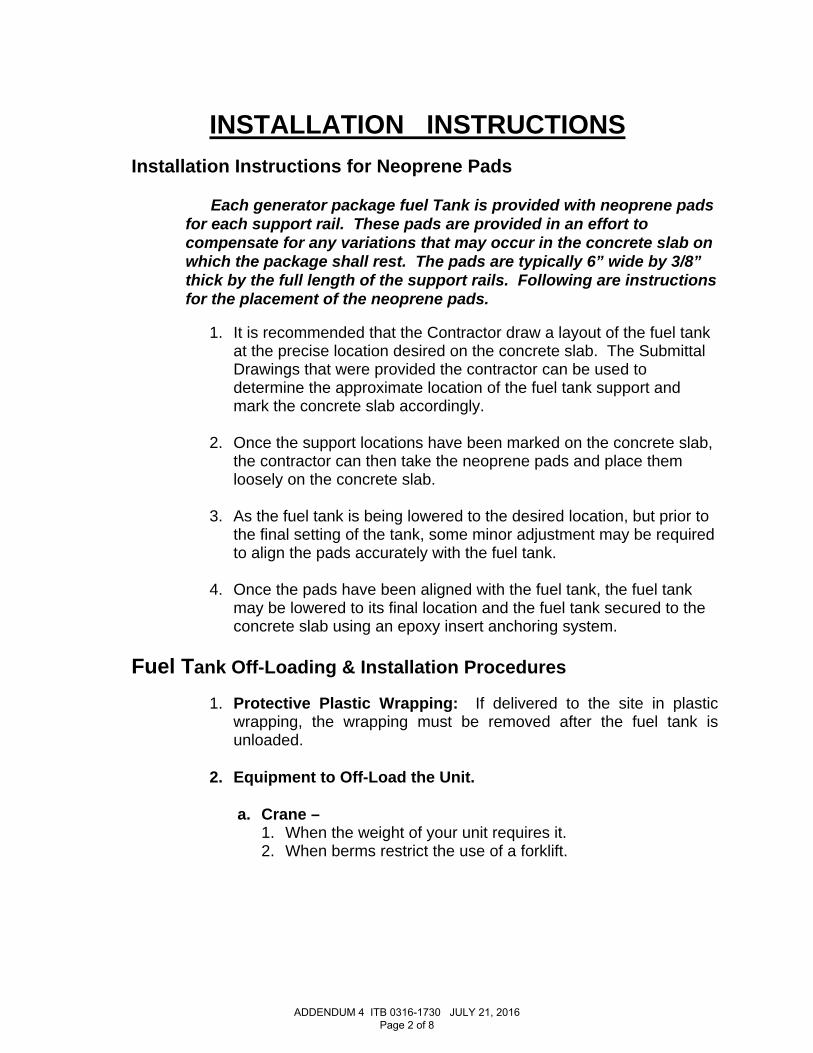
Installation Instructions for Neoprene Pads
Each generator package fuel Tank is provided with neoprene pads for each support rail. These pads are provided in an effort to compensate for any variations that may occur in the concrete slab on which the package shall rest. The pads are typically 6” wide by 3/8” thick by the full length of the support rails. Following are instructions for the placement of the neoprene pads.
1. It is recommended that the Contractor draw a layout of the fuel tank
at the precise location desired on the concrete slab. The Submittal Drawings that were provided the contractor can be used to determine the approximate location of the fuel tank support and mark the concrete slab accordingly.
2. Once the support locations have been marked on the concrete slab, the contractor can then take the neoprene pads and place them loosely on the concrete slab.
3. As the fuel tank is being lowered to the desired location, but prior to the final setting of the tank, some minor adjustment may be required to align the pads accurately with the fuel tank.
4. Once the pads have been aligned with the fuel tank, the fuel tank may be lowered to its final location and the fuel tank secured to the concrete slab using an epoxy insert anchoring system.
Fuel Tank Off-Loading & Installation Procedures
1. Protective Plastic Wrapping: If delivered to the site in plastic wrapping, the wrapping must be removed after the fuel tank is unloaded.
2. Equipment to Off-Load the Unit.
a. Crane –
1. When the weight of your unit requires it. 2. When berms restrict the use of a forklift.
ADDENDUM 4 ITB 0316-1730 JULY 21, 2016 Page 2 of 8
flickjoanne
Typewritten Text

b. Lifting Cables & Straps – Sufficient cables with hooks on each end fastened to a centering ring or spreader bar. NOTE: Wire cables can damage the paint finish and/or enclosure (if applicable). Lifting Straps of sufficient capacity should be used whenever possible. Spreader Bars are required with either cables or straps to prevent damage.
3. Procedures for off-Loading: Lifting lugs are provided for off-
loading of the tank. All lugs shall be used during the process. Lifting and rigging to be completed by qualified contractor.
4. Fuel Tank Installation: Fuel tank should be installed on a level concrete pad which extends a minimum of 12” beyond the edge of the tank in all directions. The fuel tank should be centered on the concrete and then secured by drilling holes in the slab at the tank tie-down hole locations. Secure the tank with customer supplied stainless steel expansion anchors and associated hardware. The holes in the tank support feet are 1” diameter.
5. Tank Paint Touch-up Procedures:
Note: Tank Touch-up kit is normally shipped loose inside of the Overfill Box or the Equipment Box, if applicable; this kit must be removed and stored in a cool dry location to avoid the paint hardener from hardening.
a. Sand the area immediately surrounding the damaged spot to
allow the touch-up paint to be “feathered” out to the undamaged portion of the tank. This will allow for an even appearance after the repair has been completed.
b. Apply one coat of the provided Glass Flake Epoxy using a
roller with medium to fine porosity or a fine bristled brush. The Glass Flake Epoxy should be mixed with the provided hardener in a four to one ratio of paint to hardener. (4 paint to one hardener)
c. Allow Glass Flake to set for a minimum period of one (1) hour
prior to application of Polyurethane. Glass Flake must not feel “soft” to the touch or the Polyurethane will not adhere.
d. After Glass Flake has sufficiently dried, apply one coat of the
provided Polyurethane using a roller of similar porosity as
ADDENDUM 4 ITB 0316-1730 JULY 21, 2016 Page 3 of 8
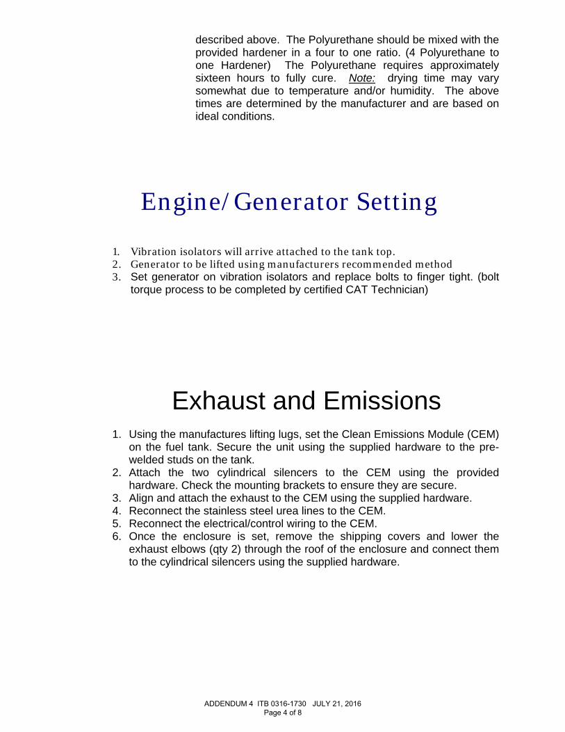
described above. The Polyurethane should be mixed with the provided hardener in a four to one ratio. (4 Polyurethane to one Hardener) The Polyurethane requires approximately sixteen hours to fully cure. Note: drying time may vary somewhat due to temperature and/or humidity. The above times are determined by the manufacturer and are based on ideal conditions.
Engine/Generator Setting
1. Vibration isolators will arrive attached to the tank top. 2. Generator to be lifted using manufacturers recommended method 3. Set generator on vibration isolators and replace bolts to finger tight. (bolt
torque process to be completed by certified CAT Technician)
Exhaust and Emissions
1. Using the manufactures lifting lugs, set the Clean Emissions Module (CEM) on the fuel tank. Secure the unit using the supplied hardware to the pre-welded studs on the tank.
2. Attach the two cylindrical silencers to the CEM using the provided hardware. Check the mounting brackets to ensure they are secure.
3. Align and attach the exhaust to the CEM using the supplied hardware. 4. Reconnect the stainless steel urea lines to the CEM. 5. Reconnect the electrical/control wiring to the CEM. 6. Once the enclosure is set, remove the shipping covers and lower the
exhaust elbows (qty 2) through the roof of the enclosure and connect them to the cylindrical silencers using the supplied hardware.
ADDENDUM 4 ITB 0316-1730 JULY 21, 2016 Page 4 of 8
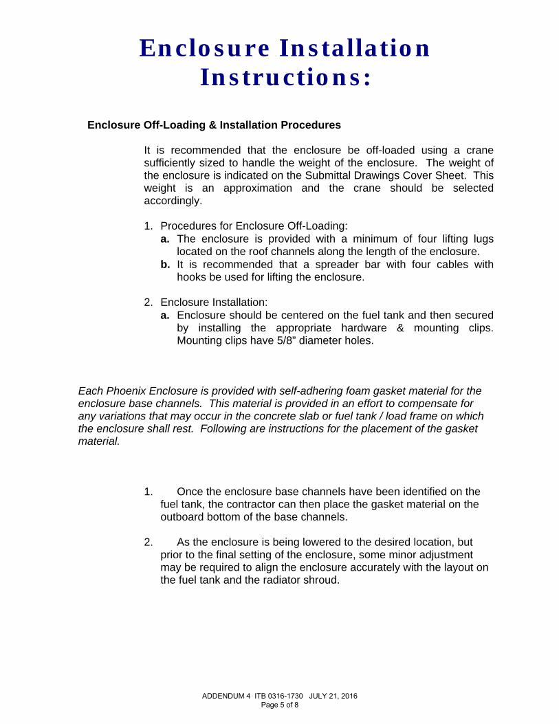
Enclosure Installation Instructions:
Enclosure Off-Loading & Installation Procedures
It is recommended that the enclosure be off-loaded using a crane
sufficiently sized to handle the weight of the enclosure. The weight of the enclosure is indicated on the Submittal Drawings Cover Sheet. This weight is an approximation and the crane should be selected accordingly.
1. Procedures for Enclosure Off-Loading:
a. The enclosure is provided with a minimum of four lifting lugs located on the roof channels along the length of the enclosure.
b. It is recommended that a spreader bar with four cables with hooks be used for lifting the enclosure.
2. Enclosure Installation:
a. Enclosure should be centered on the fuel tank and then secured by installing the appropriate hardware & mounting clips. Mounting clips have 5/8” diameter holes.
Each Phoenix Enclosure is provided with self-adhering foam gasket material for the enclosure base channels. This material is provided in an effort to compensate for any variations that may occur in the concrete slab or fuel tank / load frame on which the enclosure shall rest. Following are instructions for the placement of the gasket material.
1. Once the enclosure base channels have been identified on the
fuel tank, the contractor can then place the gasket material on the outboard bottom of the base channels.
2. As the enclosure is being lowered to the desired location, but prior to the final setting of the enclosure, some minor adjustment may be required to align the enclosure accurately with the layout on the fuel tank and the radiator shroud.
ADDENDUM 4 ITB 0316-1730 JULY 21, 2016 Page 5 of 8
Enclosure Auxiliary Re-assembly Procedures
The enclosure has been pre-assembled, wired and plumbed at Phoenix Products. Prior to shipping, some auxiliary power / electrical wiring or fuel related piping & controls may have been disconnected to allow for shipping. Any roof penetrations will be covered with Aluminum panels or other means that will need to be removed prior to installation.
1. The following list is an example of, but not limited to items that may require re-
connection / re-assembly by Contractor: a. Caterpillar 3516C-HD, 2500 kW Tier 4 Generator Set (Engine,
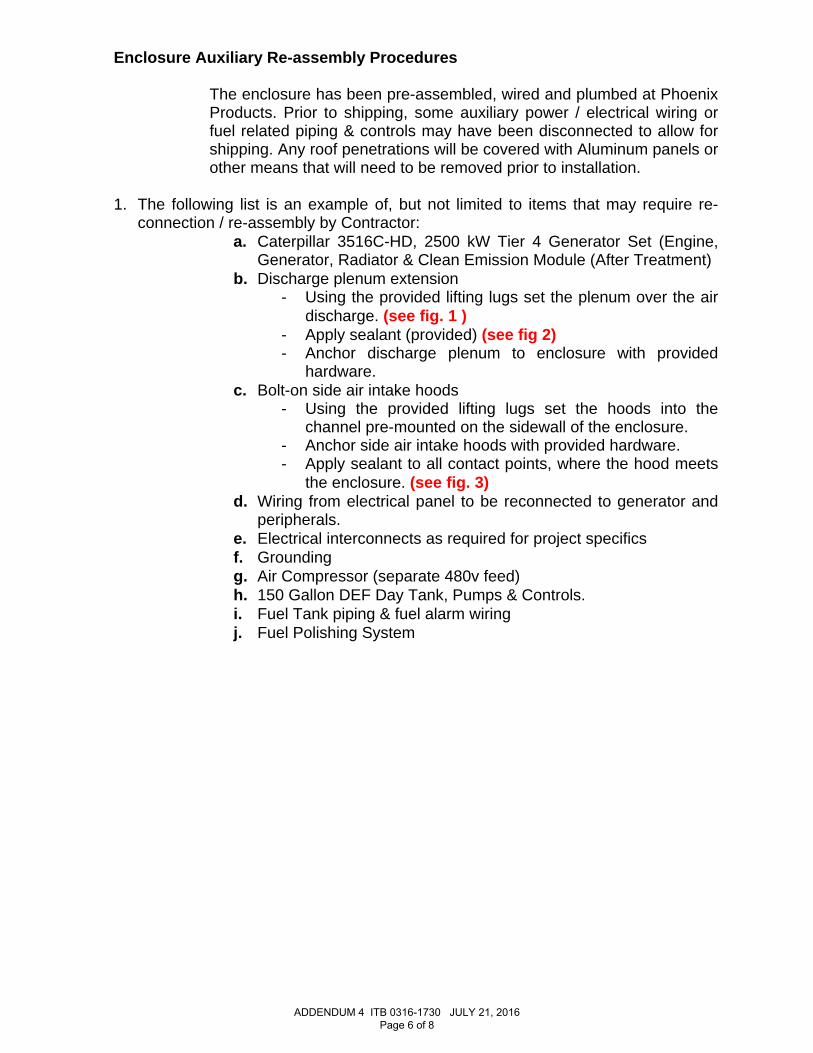
Generator, Radiator & Clean Emission Module (After Treatment) b. Discharge plenum extension
- Using the provided lifting lugs set the plenum over the air discharge. (see fig. 1 )
- Apply sealant (provided) (see fig 2) - Anchor discharge plenum to enclosure with provided
hardware. c. Bolt-on side air intake hoods
- Using the provided lifting lugs set the hoods into the channel pre-mounted on the sidewall of the enclosure.
- Anchor side air intake hoods with provided hardware. - Apply sealant to all contact points, where the hood meets
the enclosure. (see fig. 3) d. Wiring from electrical panel to be reconnected to generator and
peripherals. e. Electrical interconnects as required for project specifics f. Grounding g. Air Compressor (separate 480v feed) h. 150 Gallon DEF Day Tank, Pumps & Controls. i. Fuel Tank piping & fuel alarm wiring j. Fuel Polishing System
ADDENDUM 4 ITB 0316-1730 JULY 21, 2016 Page 6 of 8
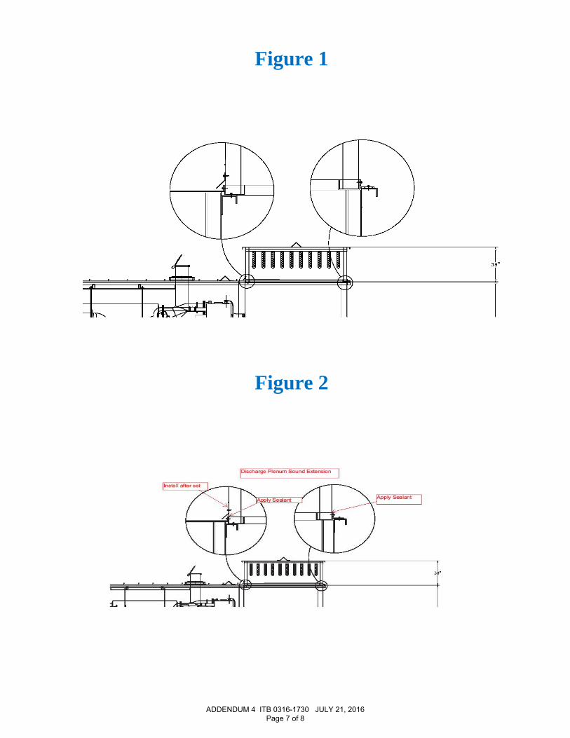
Figure 1
Figure 2
ADDENDUM 4 ITB 0316-1730 JULY 21, 2016 Page 7 of 8

Figure 3
Fig. 4
ADDENDUM 4 ITB 0316-1730 JULY 21, 2016 Page 8 of 8
Steve Dorsey
Text Box
Reconnect Onsite
Steve Dorsey
Line
Steve Dorsey
Line
Steve Dorsey
Text Box
Qty (2)
Steve Dorsey
Line
Steve Dorsey
Line
Steve Dorsey
Text Box
Qty (2) ships w/ enclosure
Steve Dorsey
Text Box
Apply Sealant to exposed connections
Steve Dorsey
Line
Steve Dorsey
Line
Steve Dorsey
Line