Sua chua may lanh cua daikin
169
Service Diagnosis SPLIT & MULTI Si10-417
-
Upload
suadiennuochanoivn -
Category
Business
-
view
373 -
download
23
Transcript of Sua chua may lanh cua daikin

Service DiagnosisSPLIT & MULTI
Si10-417
Manual
Cover.fm Page 1 Wednesday, September 22, 2004 6:36 PM

Si10-417
Contents 1
1. Diagnosis by LED ........................21.1 Indoor Unit ..................................... 21.2 Outdoor Unit .................................. 4
2. Diagnosis by Remote Controller ..62.1 To know the error code.................. 6
3. List of applicable models ...........113.1 Indoor Units ................................. 113.2 Outdoor Units .............................. 17
4. Error Codes and Description of Fault...........................................21
4.1 Indoor Unit ................................... 214.2 Outdoor Unit ................................ 224.3 System......................................... 23
5. Troubleshooting .........................245.1 Indoor Unit ................................... 245.2 Outdoor Unit ................................ 355.3 System....................................... 1245.4 Check ........................................ 149
Si10-417TOC.fm Page 1 Wednesday, September 22, 2004 6:37 PM

Diagnosis by LED Si10-417
Si10-417.fm Page 2 Wednesday, September 22, 2004 6:38 PM
1. Diagnosis by LED1.1 Indoor Unit
The operation lamp flashes when any of the following errors is detected.1. When a protection device of the indoor or outdoor unit
is activated or when the thermistor malfunctions, disabling equipment operation.
2. When a signal transmission error occurs between the indoor and outdoor units.
In either case, conduct the diagnostic procedure described in the following pages.
Wall Mounted Type
ONOFF
Indicator lamps
Operation lamp (green)
Operation lamp (green)
Indicator lamps
2 Service Diagnosis

Si10-417 Diagnosis by LED
Si10-417.fm Page 3 Wednesday, September 22, 2004 6:38 PM
Floor Ceiling Suspended Dual Type
Floor Standing Type
Duct Connected Type
OPERATION lamp (green)
ONOFF
OPERATION lamp (green)
OPERATION lamp (green)
Service Diagnosis 3

Diagnosis by LED Si10-417
Si10-417.fm Page 4 Wednesday, September 22, 2004 6:38 PM
1.2 Outdoor Unit
Pair
The outdoor unit has one green LED (LED A) on the PCB. The flashing green LED indicates normal condition of microcomputer operation.
4 Service Diagnosis

Si10-417 Diagnosis by LED
Si10-417.fm Page 5 Wednesday, September 22, 2004 6:38 PM
Multi
There are green and red LEDs on the PCB. The flashing green LED indicates normal equipment condition, and the OFF condition of the red LED indicates normal equipment condition.(Troubleshooting with the green LED)The LED A (green) of the outdoor unit indicate microcomputer operation condition.Even after the error is cancelled and the equipment operates in normal condition, the LED indication remains.
Service Diagnosis 5

Diagnosis by Remote Controller Si10-417
Si10-417.fm Page 6 Wednesday, September 22, 2004 6:38 PM
2. Diagnosis by Remote Controller2.1 To know the error code
Method 1 1. When the timer cancel button is held down for 5 seconds, a “00” indication flashes on the temperature display section.
6 Service Diagnosis

Si10-417 Diagnosis by Remote Controller
Si10-417.fm Page 7 Wednesday, September 22, 2004 6:38 PM
2. Press the timer cancel button repeatedly until a continuous beep is produced.The code indication changes in the sequence shown below, and notifies with a long beep.
Note: 1. A short beep and two consecutive beeps indicate non-corresponding codes.
2. To cancel the code display, hold the timer cancel button down for 5 seconds. The code display also cancels itself if the button is not pressed for 1 minute.
No. Code No. Code
1 00 16 A1
2 U4 17 C4
3 F3 18 C5
4 E6 19 H9
5 L5 20 J6
6 A6 21 UA
7 E5 22 A5
8 LC 23 J9
9 C9 24 E8
10 U0 25 P4
11 E7 26 L3
12 C7 27 L4
13 H8 28 H6
14 J3 29 H7
15 A3 30 U2
Service Diagnosis 7

Diagnosis by Remote Controller Si10-417
Si10-417.fm Page 8 Wednesday, September 22, 2004 6:38 PM
Method 21. Enter the diagnosis mode.
Press the 3 buttons (TEMP ,TEMP , MODE) simultaneously.
The digit of the number of tens blinks.Try again from the start when the digit does not
blink.
2. Press the TEMP button.Press TEMP or TEMP and change the digit until you hear the sound of “beep” or “pi pi”.
8 Service Diagnosis

Si10-417 Diagnosis by Remote Controller
Si10-417.fm Page 9 Wednesday, September 22, 2004 6:38 PM
3. Diagnose by the sound.“ pi ” : The number of tens does not accord with the
error code.“ pi pi ” : The number of tens accords with the error
code.“ beep ” : The both numbers of tens and units accord
with the error code. (→See 7.)
4. Enter the diagnosis mode again.Press the MODE button.
The digit of the number of units blinks.
5. Press the TEMP button.Press TEMP or TEMP and change the digit until you hear the sound of “beep”.
Service Diagnosis 9

Diagnosis by Remote Controller Si10-417
Si10-417.fm Page 10 Wednesday, September 22, 2004 6:38 PM
6. Diagnose by the sound.“ pi ” : The both numbers of tens and units do not
accord with the error code.“ pi pi ” : The number of tens accords with the error
code.“ beep ” : The both numbers of tens and units accord
with the error code.
7. Determine the error code.The digits indicated when you hear the “beep” sound are error code.(Error codes and description → Refer to page 21.)
8. Exit from the diagnosis mode.Press the MODE button.
10 Service Diagnosis

Si10-417 List of applicable models
Si10-417.fm Page 11 Wednesday, September 22, 2004 6:38 PM
3. List of applicable modelsEven the same error code may be explained on different flowchart pages. Follow the classification Nos. in the table below and check the related page according to the table on page 21.
3.1 Indoor Units3.1.1 Wall Mounted Type
Model Classification No. Model Classification
No.
AT12BV1LS 2 FTK35AVM(A)(T) 1
AT18BV1LS 2 FTK35AZVMB 1
ATK25BVMB 1 FTK35BVMB 1
ATK35BVMB 1 FTK50AVM(A)(T) 2
ATKS20CVMB(9) 1 FTK60AVM(A)(T) 2
ATKS25BVMB 1 FTK71AVM(A)(T) 2
ATKS25CVMB(9) 1 FTKD18BVMS 2
ATKS35BVMB 1 FTKD24BVMS 2
ATKS35CVMB(9) 1 FTKD28BVMS 2
ATX25BVMB 1 FTKD50BVM 2
ATX35BVMB 1 FTKD50BVMA(9) 2
ATXS20CVMB(9) 1 FTKD50BVMD 2
ATXS25BVMB 1 FTKD50BVMT 2
ATXS25CVMB(9) 1 FTKD60BVM 2
ATXS35BVMB 1 FTKD60BVMA(9) 2
ATXS35CVMB(9) 1 FTKD60BVMD 2
ATXS50CVMB 2 FTKD60BVMT 2
FT13BV1LS 2 FTKD71BVM 2
FT18BV1LS 2 FTKD71BVMA(9) 2
FT24BV1LS 2 FTKD71BVMD 2
FT50BVM 2 FTKD71BVMT 2
FT50CV1A 2 FTKE09BVMS 1
FT60BVM 2 FTKE12BVMS 1
FT60CV1A 2 FTKE25BVM 1
FTK25AVM(A)(T) 1 FTKE25BVMA(9) 1
FTK25AZVMB 1 FTKE25BVMD 1
FTK25BVMB 1 FTKE25BVMT 1
Refer the classification No. to page 21
Service Diagnosis 11

List of applicable models Si10-417
Si10-417.fm Page 12 Wednesday, September 22, 2004 6:38 PM
FTKE35BVM 1 FTX35BVMB 1
FTKE35BVMA(9) 1 FTX50AMVMC 2
FTKE35BVMD 1 FTX50AVMA 2
FTKE35BVMT 1 FTX50AVMC 2
FTKS20CVMB(9) 1 FTX50AVMT 2
FTKS25BVMB 1 FTX60AMVMC 2
FTKS25CVMB(9)(8) 1 FTX60AVMA 2
FTKS35BVMB 1 FTX60AVMC 2
FTKS35CVMB(9)(8) 1 FTX60AVMT 2
FTKS50BVMA(9) 2 FTX71AMVMC 2
FTKS50BVMB 2 FTX71AVMA 2
FTKS60BVMA(9) 2 FTX71AVMC 2
FTKS60BVMB 2 FTX71AVMT 2
FTKS71BVMA(9) 2 FTXD50BMVMC 2
FTKS71BVMB 2 FTXD50BV4(9) 2
FTN20CVMB9 1 FTXD50BVMA(9) 2
FTN25CVMB9 1 FTXD50BVMC 2
FTN35CVMB9 1 FTXD50BVMT 2
FTS20BVMB 1 FTXD50CMV2C 2
FTS25BVMB 1 FTXD60BMVMC 2
FTS35BVMB 1 FTXD60BVMA(9) 2
FTS50BVMB 2 FTXD60BVMC 2
FTS60BVMB 2 FTXD60BVMT 2
FTX25AMVMC 1 FTXD71BVMA(9) 2
FTX25AVMA 1 FTXD71BVMC 2
FTX25AVMC 1 FTXD71BVMT 2
FTX25AVMT 1 FTXD80CV4(9) 2
FTX25AZVMB 1 FTXE25BMVMC 1
FTX25BVMB 1 FTXE25BVMA(9) 1
FTX35AMVMC 1 FTXE25BVMC 1
FTX35AVMA 1 FTXE25BVMT 1
FTX35AVMC 1 FTXE35BMVMC 1
FTX35AVMT 1 FTXE35BVMA(9) 1
FTX35AZVMB 1 FTXE35BVMC 1
Model Classification No. Model Classification
No.
Refer the classification No. to page 21
12 Service Diagnosis

Si10-417 List of applicable models
Si10-417.fm Page 13 Wednesday, September 22, 2004 6:38 PM
FTXE35BVMT 1 FTXS71BVMB 2
FTXS20CVMB(9) 1 FTY25CVMA 1
FTXS25BVMB(A) 1 FTY35CVMA 1
FTXS25CVMB(9)(8) 1 FTYN20CVMB9 1
FTXS35BVMB(A) 1 FTYN25CVMB9 1
FTXS35CVMB(9)(8) 1 FTYN35CVMB9 1
FTXS50BVMA(9) 2 FTYS20BVMB 1
FTXS50BVMB 2 FTYS25BVMB 1
FTXS60BVMA(9) 2 FTYS35BVMB 1
FTXS60BVMB 2 FTYS50BVMB 2
FTXS71BVMA(9) 2 FTYS60BVMB 2
Model Classification No. Model Classification
No.
Refer the classification No. to page 21
Service Diagnosis 13

List of applicable models Si10-417
Si10-417.fm Page 14 Wednesday, September 22, 2004 6:38 PM
3.1.2 Floor Standing Type
Model Classification No.
FVK25AZVMB 2
FVK35AZVMB 2
FVK50AZVMB 2
FVKS25BVMB 2
FVKS35BVMB 2
FVKS50BVMB 2
FVX25AZVMB 2
FVX35AZVMB 2
FVX50AZVMB 2
FVX56AV1C 2
FVXD56CMV2C 2
FVXD68CMV2C 2
FVXS25BVMB 2
FVXS35BVMB(A) 2
FVXS50BVMB(A) 2
Refer the classification No. to page 21
14 Service Diagnosis

Si10-417 List of applicable models
Si10-417.fm Page 15 Wednesday, September 22, 2004 6:38 PM
3.1.3 Duct Connected Type
Model Classification No. Model Classification
No.
CDK25AVM 1 CDX35AZVMB 1
CDK25AVMA 1 CDX35BVMC(9) 1
CDK25AVMD 1 CDX50AVMA 1
CDK25AZVMB 1 CDX50AVMC(9) 1
CDK35AVM 1 CDX50AZVMB 1
CDK35AVMA 1 CDX60AVMA 1
CDK35AVMD 1 CDX60AVMC(9) 1
CDK35AZVMB 1 CDX60AZVMB 1
CDK50AVM 1 CDXD25AVMC 1
CDK50AVMA 1 CDXD25BMVMC 1
CDK50AVMD 1 CDXD25CMVMC 1
CDK50AZVMB 1 CDXD25CVMA 1
CDK60AVM 1 CDXD35AVMC 1
CDK60AVMA 1 CDXD35BMVMC 1
CDK60AVMD 1 CDXD35CMVMC 1
CDK60AZVMB 1 CDXD35CVMA 1
CDKD25CVM(A) 1 CDXD50AVMC 1
CDKD35CVM(A) 1 CDXD50CVMA 1
CDKD50CVM(A) 1 CDXD60AVMC 1
CDKD60CVM(A) 1 CDXD60BMVMC 1
CDKS25BVMB 1 CDXD60CMVMC 1
CDKS25CVMB 1 CDXD60CVMA 1
CDKS35BVMB 1 CDXS25BVMB 1
CDKS35CVMB 1 CDXS25CVMB(A) 1
CDKS50BVMB 1 CDXS35BVMB 1
CDKS50CVMB 1 CDXS35CVMB(A) 1
CDKS60BVMB 1 CDXS50BVMB 1
CDKS60CVMB 1 CDXS50CVMB(A) 1
CDX25AVMA 1 CDXS60BVMB 1
CDX25AZVMB 1 CDXS60CVMB(A) 1
CDX25BVMC(9) 1 FDXD50BMVMC 1
CDX35AVMA 1 FDXD50CMVMC 1
Refer the classification No. to page 21
Service Diagnosis 15

List of applicable models Si10-417
Si10-417.fm Page 16 Wednesday, September 22, 2004 6:38 PM
3.1.4 Floor / Ceiling Suspended Dual Type
Model Classification No.
FLK25AVMA 1
FLK25AVMD 1
FLK25AZVMB 1
FLK25BVMB 1
FLK35AVMA 1
FLK35AVMD 1
FLK35AZVMB 1
FLK35BVMB 1
FLK50AVMA 1
FLK50AVMD 1
FLK50AZVMB 1
FLK60AVMA 1
FLK60AVMD 1
FLK60AZVMB 1
FLKS25BVMB 1
FLKS35BVMB 1
FLKS50BVMB 1
FLKS60BVMB 1
FLX25AVMA 1
FLX25AZVMB 1
FLX25BVMB 1
FLX35AVMA 1
FLX35AZVMB 1
FLX35BVMB 1
FLX50AVMA 1
FLX50AZVMB 1
FLX60AVMA 1
FLX60AZVMB 1
FLXS25BVMB(A) 1
FLXS35BVMB(A) 1
FLXS50BVMB(A) 1
FLXS60BVMB(A) 1
Refer the classification No. to page 21
16 Service Diagnosis

Si10-417 List of applicable models
Si10-417.fm Page 17 Wednesday, September 22, 2004 6:38 PM
3.2 Outdoor Units
Model Classification No. Model Classification
No.
2AMKS40BVMB 6 4MKD75BVM 5
2AMXS40BVMB 6 4MKS58BVMB 5
2MK58AVM 5 4MKS75BVMB 5
2MK58AVM 5 4MX68AZVMB 5
2MKD58BVM 5 4MXS68BVMB 5
2MKS40BVMB 6 4MXS68BVMB9 5
2MXS40BVMB 6 AR09BV1LS 3
3AMXS52BVMB 5 AR25AV1B 3
3MK58AVM 5 AR25AV1B9 3
3MK58AVM 5 AR35AV1B 3
3MK75AVM 5 AR35AV1B9 3
3MK75AVM 5 ARK25BVMB 3
3MK75AVMA 5 ARK35BVMB 3
3MK75AVMT 5 ARKH20CVMB9 3
3MKD58BVM 5 ARKH25CVMB9 3
3MKD75BVM 5 ARKH35CVMB9 3
3MKD75BVMA 5 ARKS25BVMB 3
3MKD75BVMT 5 ARKS35BVMB 3
3MKS50BVMB 5 ARX25BVMB 3
3MX52AZVMB 5 ARX35BVMB 3
3MX68AVMA 5 ARXH20CVMB9 3
3MX68AVMC 5 ARXH25CVMB9 3
3MX68AVMT 5 ARXH35CVMB9 3
3MXD68BVMA 5 ARXS25BVMB 3
3MXD68BVMC 5 ARXS35BVMB 3
3MXD68BVMT 5 ARXS50CVMB 4
3MXD80BMVMC 5 R25CV1A 3
3MXS52BVMB 5 R25JV16 3
4MK58AZVMB 5 R25JV17 3
4MK75AVM 5 R25JV1A 3
4MK75AVM 5 R35CV1A 3
4MK75AZVMB 5 R35JV16 3
Refer the classification No. to page 22
Service Diagnosis 17

List of applicable models Si10-417
Si10-417.fm Page 18 Wednesday, September 22, 2004 6:38 PM
R35JV17 3 RKD60JVE 4
R35JV1A 3 RKD60JVEA 4
RE09JV1LS 3 RKD60JVET 4
RE12JV1LS 3 RKD71BVM 4
RE25JV1 3 RKD71BVMA 4
RE25JV1C 3 RKD71BVMT 4
RE35JV1 3 RKD71JVE 4
RE35JV1C 3 RKD71JVEA 4
REY22GV1B 3 RKD71JVET 4
REY35GV1B 3 RKD80BVMA 4
RK25BVMB 3 RKE09BVMS 3
RK25JAVET 3 RKE12BVMS 3
RK25JV1NB9 3 RKE25BVM 3
RK25JVE9 3 RKE25BVMA 3
RK25JVEA9 3 RKE25BVMT 3
RK35BVMB 3 RKE35BVM 3
RK35JAVET 3 RKE35BVMA 3
RK35JV1NB9 3 RKE35BVMT 3
RK35JVE9 3 RKH20CVMB9 3
RK35JVEA9 3 RKH25CVMB9 3
RKD18BVMS 4 RKH35CVMB9 3
RKD24BVMS 4 RKS25BVMB 3
RKD25KZV1B 3 RKS35BVMB 3
RKD28BVMS 4 RKS50BVMA 4
RKD35KZV1B 3 RKS50BVMB 4
RKD50BVM 4 RKS50BVMB9 4
RKD50BVMA 4 RKS60BVMA 4
RKD50BVMT 4 RKS60BVMB 4
RKD50JVE9 4 RKS60BVMB9 4
RKD50JVEA9 4 RKS71BVMA 4
RKD50JVET 4 RKS71BVMB 4
RKD60BVM 4 RKS71BVMB9 4
RKD60BVMA 4 RN20CVMB9 3
RKD60BVMT 4 RN25CVMB9 3
Model Classification No. Model Classification
No.
Refer the classification No. to page 22
18 Service Diagnosis

Si10-417 List of applicable models
Si10-417.fm Page 19 Wednesday, September 22, 2004 6:38 PM
RN35CVMB9 3 RXD50JV1B 4
RS20BVMB 3 RXD50JV1B5 4
RS25BVMB 3 RXD50JVEA9 4
RS35BVMB 3 RXD50JVET 4
RS50BVMB 4 RXD60BVMA 4
RS50BVMB 4 RXD60BVMT 4
RS60BVMB 4 RXD60JV1B 4
RX25BVMB 3 RXD60JV1B5 4
RX25JAVET 3 RXD60JVEA 4
RX25JV1NB5 3 RXD60JVET 4
RX25JV1NB9 3 RXD68CMV2C 4
RX25JVEA9 3 RXD71BMVMC 4
RX25LV1C 3 RXD71BVMA 4
RX25LV1C9 3 RXD71BVMT 4
RX35BVMB 3 RXD71JV1B 4
RX35JAVET 3 RXD71JV1B5 4
RX35JV1NB5 3 RXD71JVEA 4
RX35JV1NB9 3 RXD71JVET 4
RX35JVEA9 3 RXD80BVMA 4
RX35LV1C 3 RXD80CV4 4
RX35LV1C9 3 RXE25BVMA 3
RX50AZVMB 4 RXE25BVMT 3
RX50JV4N 4 RXE25CMV2C 3
RX56AV1C 4 RXE35BVMA 3
RX60AZVMB 4 RXE35BVMT 3
RX71AZVMB 4 RXE35CMV2C 3
RXD25KZV1B 3 RXH20CVMB9 3
RXD35KZV1B 3 RXH25CVMB9 3
RXD50BMVMC 4 RXH35CVMB9 3
RXD50BV4 4 RXS25BVMB 3
RXD50BVMA 4 RXS35BVMB 3
RXD50BVMT 4 RXS35BVMB 3
RXD50CMVMC 4 RXS50BVMA 4
RXD50JV1B 4 RXS50BVMB 4
Model Classification No. Model Classification
No.
Refer the classification No. to page 22
Service Diagnosis 19

List of applicable models Si10-417
Si10-417.fm Page 20 Wednesday, September 22, 2004 6:38 PM
RXS60BVMA 4 RYN25CVMB9 3
RXS60BVMB 4 RYN35CVMB9 3
RXS71BVMA 4 RYS20BVMB 3
RXS71BVMB 4 RYS25BVMB 3
RY25CVMA 3 RYS35BVMB 3
RY35CVMA 3 RYS50BVMB 4
RYN20CVMB9 3 RYS60BVMB 4
Model Classification No. Model Classification
No.
Refer the classification No. to page 22
20 Service Diagnosis
Si10-417 Error Codes and Description of Fault
Si10-417.fm Page 21 Wednesday, September 22, 2004 6:38 PM
4. Error Codes and Description of Fault
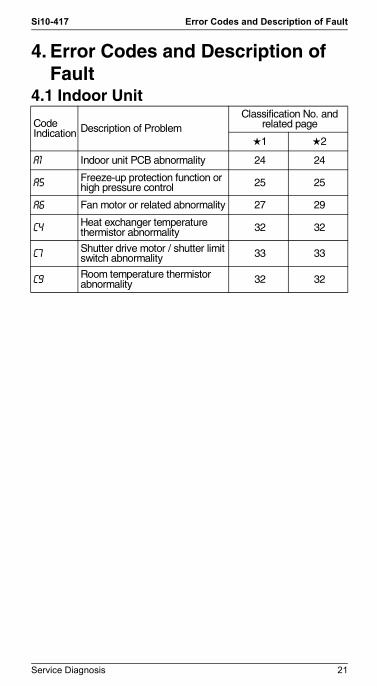
4.1 Indoor Unit
Code Indication Description of Problem
Classification No. and related page
1 2
A1 Indoor unit PCB abnormality 24 24
A5 Freeze-up protection function or high pressure control 25 25
A6 Fan motor or related abnormality 27 29
C4 Heat exchanger temperature thermistor abnormality 32 32
C7 Shutter drive motor / shutter limit switch abnormality 33 33
C9 Room temperature thermistor abnormality 32 32
Service Diagnosis 21

Error Codes and Description of Fault Si10-417
Si10-417.fm Page 22 Wednesday, September 22, 2004 6:38 PM
4.2 Outdoor Unit
Code Indication Description of Problem
Classification No. and related page
3 4 5 6
A5Anti-icing function — — — 35
Freeze-up protection — — 37 —
E5 OL activation (compressor overloaded) 39 40 41 39
E6 Compressor lock 43 44 45 47
E7 DC fan lock — 48 49 48
E8 Input over current detection 50 52 54 56
EA Four way valve abnormality 58 60 62 64
F3 Discharge pipe temperature control 66 68 70 72
F6 High pressure control in cooling 74 74 — 75
H6 Position sensor abnormality 77 79 81 83
H8 CT or related abnormality 85 87 89 91
H9 Outdoor air thermistor or related abnormality 93 93 95 97
J3 Discharge pipe thermistor or related abnormality 93 93 95 97
J6 Heat exchanger thermistor or related abnormality 93 93 95 97
J8 Liquid pipe thermistor or related abnormality — — 95 97
J9 Gas pipe thermistor or related abnormality — — 95 97
L3 Electrical box temperature rise 99 101 103 105
L4 Radiation fin temperature rise 107 109 111 113
L5 Output over current detection 115 115 118 121
P4 Radiation fin thermistor or related abnormality 93 93 95 97
22 Service Diagnosis

Si10-417 Error Codes and Description of Fault
Si10-417.fm Page 23 Wednesday, September 22, 2004 6:38 PM
4.3 System
Code Indication Description of Problem
Classification No. and related page
3 4 5 6
00 Normal — — — —
U0 Insufficient gas 124 127 130 133
U2Low-voltage detection — 137 138 —
Over-voltage detection 136 — — 140
U4
Signal transmission error (between indoor and outdoor units)
142 142 — 142
Outdoor unit PCB abnormality or signal transmission circuit abnormality
— — 144 —
UA Unspecified voltage (between indoor and outdoor units) 146 146 147 148
UH Anti-icing function in other rooms — — 147 148
Service Diagnosis 23

Troubleshooting Si10-417
Si10-417.fm Page 24 Wednesday, September 22, 2004 6:38 PM
5. Troubleshooting5.1 Indoor Unit5.1.1 Indoor Unit PCB Abnormality
Remote Controller Display
A1
Method of Malfunction Detection
Evaluation of zero-cross detection of power supply by indoor unit.
MalfunctionDecision Conditions
When there is no zero-cross detection in approximately 10 continuous seconds.
Supposed Causes
Faulty indoor unit PCBFaulty connector connection
Troubleshooting
Note: Connector Nos. vary depending on models.Control connector
Connector connection check (note).
YES
Is it normal? NOCorrect connections.
Replace PCBs.
(R1400)
CautionBe sure to turn off power switch before connect or disconnect connector, or parts damage may be occurred.
Model Type Connector No.
Wall Mounted Type 20/25/35 class
Terminal strip~Control PCB
Wall Mounted Type 50/60/71 class
Terminal strip~Control PCB
Ceiling Embedded Duct Type Terminal strip~Control PCB
Duct Connected Type Terminal strip~Control PCB
Floor / Ceiling Suspended Dual Type
S37
Floor Standing Type Control PCB : S7, S201, S203Power Supply PCB : S8, S202, S204
24 Service Diagnosis

Si10-417 Troubleshooting
Si10-417.fm Page 25 Wednesday, September 22, 2004 6:38 PM
5.1.2 Freeze-up Protection Control or High Pressure Control
Remote Controller Display
A5
Method of Malfunction Detection
High pressure control (heat pump model only)During heating operations, the temperature detected by the indoor heat exchanger thermistor is used for the high pressure control (stop, outdoor fan stop, etc.) The freeze-up protection control (operation halt) is activated during cooling operation according to the temperature detected by the indoor unit heat exchanger thermistor.
Malfunction Decision Conditions
High pressure controlDuring heating operations, the temperature detected by the indoor heat exchanger thermistor is above 65°CFreeze-up protectionWhen the indoor unit heat exchanger temperature is below 0°C during cooling operation.
Supposed Causes
Operation halt due to clogged air filter of the indoor unit.Operation halt due to dust accumulation on the indoor unit heat exchanger.Operation halt due to short-circuit.Detection error due to faulty indoor unit heat exchanger thermistor.Detection error due to faulty indoor unit PCB.
Service Diagnosis 25

Troubleshooting Si10-417
Si10-417.fm Page 26 Wednesday, September 22, 2004 6:38 PM
Troubleshooting
Check No.6Refer to
P.157
Note: If the outside temperature is below –10°C in the cooling mode, the system may get interrupted with error A5 displayed. The system will be reset itself, but this stop will be put in the error history memory.
NO
NO
NOCheck No. 6Indoor unit heat exchanger thermistor check
Check the intake air filter.
Check the air passage.
YES
YES
(R1401)
Check the dust accumulation on the indoor unit heat exchanger.
YES
YES
Is there anyshort-circuit?
Is it very dirty?
Is it very dirty?
NO
Provide sufficient air passage.
Clean the air filter.
Clean the heat exchanger.
Replace the indoor unit PCB.
Replace the thermistor (replace the indoor unit PCB).
CautionBe sure to turn off power switch before connect or disconnect connector, or parts damage may be occurred.
Does itconform to the
thermistor characteristicchart?
26 Service Diagnosis

Si10-417 Troubleshooting
Si10-417.fm Page 27 Wednesday, September 22, 2004 6:38 PM
5.1.3 Fan Motor (AC Motor) or Related Abnormality
Remote Controller Display
A6
Method of Malfunction Detection
The rotation speed detected by the Hall IC during fan motor operation is used to determine abnormal fan motor operation.
Malfunction Decision Conditions
When the detected rotation speed is less than 50% of the HH tap under maximum fan motor rotation demand.
Supposed Causes
Operation halt due to short circuit inside the fan motor winding.Operation halt due to breaking of wire inside the fan motor.Operation halt due to breaking of the fan motor lead wires.Operation halt due to faulty capacitor of the fan motor.Detection error due to faulty indoor unit PCB.
Troubleshooting
Check No.16Refer to
P.167Rotate the fan by hand.
Operate the fan.
Does it rotate?
NO
Does it rotate smoothly?
Is it at the rated voltage?
Is thereconductivity?
NO
Check the capacitor's conductivity
Check the fan motor voltage.(immediately after re-start)
NO
NO
YES
YES
YES
YES
Replace the fan motor∗2 Measure the voltage between the red and black lead wires of the fan motor, and check if the maximum voltage reaches the rated voltage.Replace the indoor unit PCB (1)
Replace the capacitor.(Replace PCB (1).)
Replace the fan motor.
CautionBe sure to turn off power switch before connect or disconnect connector, or parts damage may be occurred.
A
Service Diagnosis 27

Troubleshooting Si10-417
Si10-417.fm Page 28 Wednesday, September 22, 2004 6:38 PM
(R1946)
Check No. 16Check hall IC
Is there an output?
Is it at therated voltage?
Check the fan motor voltage.
NO
NO
YES
YES
Replace the fan motor or indoor unit PCB.
Replace indoor unit PCB (1).
Replace the fan motor.
A
28 Service Diagnosis

Si10-417 Troubleshooting
Si10-417.fm Page 29 Wednesday, September 22, 2004 6:38 PM
5.1.4 Fan Motor (DC Motor) or Related Abnormality
Remote Controller Display
A6
Method of Malfunction Detection
The rotation speed detected by the Hall IC during fan motor operation is used to determine abnormal fan motor operation.
Malfunction Decision Conditions
When the detected rotation speed is less than 50% of the H tap under maximum fan motor rotation demand.
Supposed Causes
Operation halt due to short circuit inside the fan motor winding.Operation halt due to breaking of wire inside the fan motor.Operation halt due to breaking of the fan motor lead wires.Operation halt due to faulty capacitor of the fan motor.Detection error due to faulty indoor unit PCB (1).
Service Diagnosis 29

Troubleshooting Si10-417
Si10-417.fm Page 30 Wednesday, September 22, 2004 6:38 PM
Troubleshooting
Check No.1Refer to
P.149
Check No.2Refer to
P.150
Replace fan motor.
Replace indoor Replace fan motor.
Replace indoor unit PCB (2) .
Turn off power supply and rotate fan by hand.
Turn power ON and operate fan.
Does it rotate?
Stop fan motor.
Is rotation number command pulse
generated?
Check No.01Check output of fan motor connector
Doesfan rotate smoothly?
YES
YES
NO
YES
NO
NO
CautionBe sure to turn off power switch before connect or disconnect connector, or parts damage may be occurred.
A
30 Service Diagnosis

Si10-417 Troubleshooting
Si10-417.fm Page 31 Wednesday, September 22, 2004 6:38 PM
Replace indoor unit PCB (1) .
Replace fan motor.Note : Motor may
break when the motor connector is disconnected while remaining power supply.
Replace fan motor and indoor PCB (2) .
Replace indoor unit PCB (2) .
Turn off power supply and disconnect fan motor conn-ector, then turn power ON.
Check No.01Check output of fan motor connector
Is motorpower voltage DC 200V
generated?
Is motor control power
voltage DC 15V generated?
Turn off power supply and dis-connect fan motor connector,then turn power ON again.
Is rotation number command pulse
generated?
Check No.01Check output of fan motor connector
Check No.01Check output of fan motor connector
Is rotation number command voltage
DC 5V generated?
YES
YES
NO
YES
NO
NO
YES
NO
A
B
Replace indoor unit PCB (1) .
Replace indoor unit PCB (2) .
Check No.02Check output of indoor unit PCB (1)
Is motor control power voltage DC 16V
generetad?
(R1214)
YES
NO
B
Service Diagnosis 31

Troubleshooting Si10-417
Si10-417.fm Page 32 Wednesday, September 22, 2004 6:38 PM
5.1.5 Thermistor or Related Abnormality(Indoor Unit)
Remote Controller Display
C4, C9
Method of Malfunction Detection
The temperatures detected by the thermistors are used to determine thermistor errors.
Malfunction Decision Conditions
When the thermistor input is more than 4.96 V or less than 0.04 V during compressor operation*.* (reference)When above about 212°C (less than 120 ohms) or below about -50°C (more than 1,860 kohms).
Note: The values vary slightly in some models.
Supposed Causes
Faulty connector connectionFaulty thermistorFaulty PCB
Troubleshooting
Check No.6Refer to
P.157
C4 : Heat exchanger temperature thermistorC9 : Room temperature thermistor
CautionBe sure to turn off power switch before connect or disconnect connector, or parts damage may be occurred.
Check the connector connection.
YES
Correct the connection.
Replace the thermistor.(Replace the indoor unit PCB.)Replace the indoor unit PCB.
Is it normal?
Is it normal?
(R1403)
NO
Check No. 6Thermistor resistance check
YES
NO
32 Service Diagnosis

Si10-417 Troubleshooting
Si10-417.fm Page 33 Wednesday, September 22, 2004 6:38 PM
5.1.6 Shutter Drive Motor / Shutter Limit Switch Abnormality
Remote Controller Display
C7
Method of Malfunction Detection
The shutter open / close performance is detected by the limit switch attached on its structure. In this way, the shutter drive motor and the shutter limit switch are checked for failure.
Malfunction Decision Conditions
When the shutter is open, the limit switch is closed.
Supposed Causes
Shutter drive motor defectiveShutter limit switch defectiveShutter itself deformed (warped)Shutter's sealing material too thickDetection error by broken relay harness or disconnected connectorDetection error due to defective PCB (2)Foreign substance in blow port
Troubleshooting
Check No.3Refer to
P.150
CautionBe sure to turn off power switch before connect or disconnect connector, or parts damage may be occurred.
Turn off the power.
Check No. 3Check the limit switch continuity.
Remove such substance.
Replace the limit switch.
Foreignsubstance in the shutter
structure?
YES
NO
Shutter closed?NO
NO
YES
YES
Limit switch on power?
Open the shutter and turn on the power.
A
2A
Service Diagnosis 33

Troubleshooting Si10-417
Si10-417.fm Page 34 Wednesday, September 22, 2004 6:38 PM
Check the shutter's sealing material.
Check the shutter for deformation or its sealing material.
NO
2A
Shutteropening itself?
YES
(Q0346)
Reconnect the connector or replace the relay harness.
Replace the shutter drive motor or the PC board (2).
YES
NO
Relay harness broken or connector
disconnected?
A
34 Service Diagnosis

Si10-417 Troubleshooting
Si10-417.fm Page 35 Wednesday, September 22, 2004 6:38 PM
5.2 Outdoor Unit5.2.1 Anti-icing Function
Remote Controller Display
A5
Method of Malfunction Detection
Indoor unit icing, during cooling operation, is detected by checking the temperatures sensed by the indoor unit heat exchanger temperature thermistor and room temperature thermistor that are located in a shut-down room.At another room (the indoor unit is normal), “UH” is displayed on the remote controller.
Malfunction Decision Conditions
In the cooling mode, the following conditions (A) and (B) are kept together for 5 minutes.(A) Indoor unit heat exchanger temperature ≤ –1°C(B) Indoor unit heat exchanger temperature ≤ Room
temperature –10°CIf the indoor unit anti-icing function is activated four times continuity, the system will be shut down. (The 4-time counter will reset itself if any of the following errors does not occur during the compressor running time (total time): OL, radiation fin temperature rise, insufficient gas, and compressor lock.)
<Total 60 minutes>
Supposed Causes
Wrong wiring or pipingEv malfunctioning in each roomShort-circuitIndoor unit heat exchanger temperature thermistor abnormalityRoom temperature thermistor abnormality
Service Diagnosis 35

Troubleshooting Si10-417
Si10-417.fm Page 36 Wednesday, September 22, 2004 6:38 PM
Troubleshooting
Check No.4Refer to
P.151
Check No.6Refer to
P.157
CautionBe sure to turn off power switch before connect or disconnect connector, or parts damage may be occurred.
Check the wiring and piping.
Check No. 4Check the electronic expansion valve.
Correct the wiring or piping error.
Replace the defective Ev or coil.
Replace the heat exchanger thermistor.
Replace the room temperature thermistor.
Replace the room temperature thermistor or indoor unit heat exchanger thermistor.Do the vacuum-drying.
Replace the indoor unit PCB.
(R3039)
Wiring orpiping out of spec?
YES
NO
NO
YES
YES
YESError again?
Normal?
Thermistoras specified in its
characteristicchart?
Thermistoras specified in its
characteristicchart?
Change the gas to let moisture out of the unit (after drawing a vacuum).
Check No. 6Check the outdoor unit heat exchanger thermistor.
Check No. 6Check the room temperature thermistor.
NO
NO
NO
YES
36 Service Diagnosis

Si10-417 Troubleshooting
Si10-417.fm Page 37 Wednesday, September 22, 2004 6:38 PM
5.2.2 Freeze-up Protection Control
Remote Controller Display
A5
Outdoor Unit LED Display
A 5 1 4 2 1 3 4 4 4
Method of Malfunction Detection
Indoor unit icing, during cooling operation, is detected by checking the temperatures sensed by the indoor unit heat exchanger thermistor and room temperature thermistor that are located in a shut-down room.
Malfunction Decision Conditions
In the cooling mode, the following conditions (A) and (B) are kept together for 5 minutes.(A) Indoor unit heat exchanger temperature ≤ –1°C(B) Indoor unit heat exchanger temperature ≤ Room
temperature –10°CIf the indoor unit icing protector is activated four times straight, the system will be shut down. (The 4-time counter will reset itself if any of the following errors does not occur during the compressor running time (total time): OL, radiation fin temperature rise, gas shortage, and compressor startup.)<Total 60 minutes>
Supposed Causes
Wrong wiring or pipingEv malfunctioning in each roomShort-circuitIndoor unit heat exchanger thermistor defectiveIndoor unit thermistor defective
Service Diagnosis 37

Troubleshooting Si10-417
Si10-417.fm Page 38 Wednesday, September 22, 2004 6:38 PM
Troubleshooting
Check No.4Refer to
P.151
Check No.6Refer to
P.157
CautionBe sure to turn off power switch before connect ordisconnect connector, or parts damage may be occurred.
Check the wiring and piping.
Check No. 4Check the electronic expansion valve.
Activate the wiring error check mode.
Replace the defective Ev or coil.
Replace the heat exchanger thermistor.
Replace the room temperature thermistor.
Replace the room temperature thermistor or indoor unit heat exchanger thermistor.Do the vacuum-drying.
Replace the indoor unit PCB and then start the wiring error check mode.
(R3059)
Wiring orpiping out of spec?
YES
NO
NO
YES
YES
Error again?
Motor functioning?
YES
Thermistoras specified in its
characteristicchart?
Thermistoras specified in its
characteristicchart?
Change the gas to letmoisture out of the unit (after drawing a vacuum).
Check No. 6Check the outdoor unit heat exchanger thermistor.
Check No. 6Check the room temperature thermistor.
NO
NO
YES
NO
38 Service Diagnosis

Si10-417 Troubleshooting
Si10-417.fm Page 39 Wednesday, September 22, 2004 6:38 PM
5.2.3 OL Activation (Compressor Overload)
Remote Controller Display
E5
Method of Malfunction Detection
A compressor overload is detected through compressor OL.
Malfunction Decision Conditions
If the compressor OL is activated twice, the system will be shut down.The error counter will reset itself if this or any other error does not occur during the following 60-minute compressor running time (total time).
* The operating temperature condition is not specified.
Supposed Causes
Refrigerant shortageFour way valve malfunctioningOutdoor unit PCB defectiveWater mixed in the local pipingElectronic expansion valve defectiveStop valve defective
Troubleshooting
Check No.4Refer to
P.151
CheckNo.5-2
Refer toP.156
Check No.6Refer to
P.157
Check No.11Refer to
P.162
CautionBe sure to turn off power switch before connect or disconnect connector, or parts damage may be occurred.
Insert the thermistor in position.
Replace the discharge pipe thermistor.
Replace the valve itself or the coil.
Replace the four way valve coil or the valve itself.Replace the outdoor unit PCB.
Refer to the refrigerant line check procedure.
Replace the outdoor unit PCB.
(R2841)
Discharge pipe thermistor disconnected?
YES
Malfunctioning
∗ Discharge pipe thermistor
NO
Functioning
Functioning
Functioning
Functioning
Check No. 11Check the refrigerant
line.
Malfunctioning
Malfunctioning
∗ Refrigerant shortage∗ Water mixed∗ Stop valve defective
Malfunctioning
Check No. 6Check the thermistors
Check No. 4Check the electronic
expantion valve.
Check No. 5-2Check the four way
valve.
Service Diagnosis 39

Troubleshooting Si10-417
Si10-417.fm Page 40 Wednesday, September 22, 2004 6:38 PM
5.2.4 OL Activation (Compressor Overload)
Remote Controller Display
E5
Method of Malfunction Detection
A compressor overload is detected through compressor OL.
Malfunction Decision Conditions
If the compressor OL is activated twice, the system will be shut down.The error counter will reset itself if this or any other error does not occur during the following 60-minute compressor running time (total time).
* The operating temperature condition is not specified.
Supposed Causes
Refrigerant shortageFour way valve malfunctioningOutdoor unit PCB defectiveWater mixed in the local pipingElectronic expansion valve defectiveStop valve defective
Troubleshooting
Check No.4Refer to
P.151
CheckNo.5-1
Refer toP.155
Check No.6Refer to
P.157
Check No.11Refer to
P.162
Dischargepipe thermistordisconnected?
Check No. 11Check the refrigerant
line.
Check No. 6Check the thermistors
Check No. 4Check the electronic
expantion valve.
Check No. 5-1Check the four way
valve.
CautionBe sure to turn off power switch before connect or disconnect connector, or parts damage may be occurred.
Insert the thermistor in position.
Replace the discharge pipe thermistor.
Replace the valve itself or the coil.
Replace the four way valve coil or the valve itself.Replace the outdoor unit PCB.
Refer to the refrigerant line check procedure.
Replace the outdoor unit PCB.
(R2841)
YES
Malfunctioning
∗ Discharge pipe thermistor
NO
Functioning
Functioning
Functioning
Functioning
Malfunctioning
Malfunctioning
∗ Refrigerant shortage∗ Water mixed∗ Stop valve defective
Malfunctioning
40 Service Diagnosis

Si10-417 Troubleshooting
Si10-417.fm Page 41 Wednesday, September 22, 2004 6:38 PM
5.2.5 OL Activation (Compressor Overload)
Remote Controller Display
E5
Outdoor Unit LED Display
A 5 1 4 2 1 3 4 4 1
Method of Malfunction Detection
A compressor overload is detected through compressor OL.
Malfunction Decision Conditions
If the compressor OL is activated twice, the system will be shut down.The error counter will reset itself if this or any other error does not occur during the following 60-minute compressor running time (total time).
* The operating temperature condition is not specified.
Supposed Causes
Refrigerant shortageFour way valve malfunctioningOutdoor unit PCB defectiveWater mixed in the local pipingElectronic expansion valve defectiveShut-off valve defective
Service Diagnosis 41

Troubleshooting Si10-417
Si10-417.fm Page 42 Wednesday, September 22, 2004 6:38 PM
Troubleshooting
Check No.4Refer to
P.151
CheckNo.5-1
Refer toP.155
Check No.6Refer to
P.157
Check No.11Refer to
P.162
Discharge pipe thermistordisconnected?
Check No. 11Check the refrigerant
line.
Check No. 6Check the thermistors
Check No. 4Check the electronic
expantion valve.
Check No. 5-1Check the four way
valve.
CautionBe sure to turn off power switch before connect or disconnect connector, or parts damage may be occurred.
Insert the thermistor in position.
Replace the discharge pipe thermistor.
Replace the valve itself or the coil.
Replace the four way valve coil or the valve itself.Replace the outdoor unit PCB.
Refer to the refrigerant line check procedure.
Replace the outdoor unit PCB.
(R2841)
YES
Malfunctioning
∗ Discharge pipe thermistor
NO
Functioning
Functioning
Functioning
Functioning
Malfunctioning
Malfunctioning
∗ Refrigerant shortage∗ Water mixed∗ Stop valve defective
Malfunctioning
42 Service Diagnosis
Si10-417 Troubleshooting
Si10-417.fm Page 43 Wednesday, September 22, 2004 6:38 PM
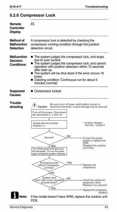
5.2.6 Compressor Lock
Remote Controller Display
E6
Method of Malfunction Detection
A compressor lock is detected by checking the compressor running condition through the position detection circuit.
Malfunction Decision Conditions
The system judges the compressor lock, and stops due to over current.The system judges the compressor lock, and cannot operation with position detection within 15 seconds after start up.The system will be shut down if the error occurs 16 times.Clearing condition: Continuous run for about 5 minutes (normal)
Supposed Causes
Compressor locked
Troubleshooting
Note: If the model doesn’t have SPM, replace the outdoor unit PCB.
Turn off the power. Disconnect the harnesses U, V and W.
∗ Inverter checker Part No.: 1225477
Correct the power supply or replace the SPM. (Replace the outdoor unit PCB.)
Replace the compressor.
Check the electronic expansion valve. Replace it as required.
Replace the compressor.(R2842)
NO
YES
YES
System shutdown after errors repeated
several times?
NO
NO
Normal?
Emergency stopwithout compressor
running?
Check with the inverter checker (∗).
Turn off the power and reconnect the harnesses. Turn on the power again and get the system restarted.
YES
CautionBe sure to turn off power switch before connect or disconnect connector, or parts damage may be occurred.
Service Diagnosis 43

Troubleshooting Si10-417
Si10-417.fm Page 44 Wednesday, September 22, 2004 6:38 PM
5.2.7 Compressor Lock
Remote Controller Display
E6
Method of Malfunction Detection
A compressor lock is detected by checking the compressor running condition through the position detection circuit.
Malfunction Decision Conditions
The position detection circuit detects a compressor frequency of below 10 Hz for 20 seconds or a frequency of above 160 Hz.40 seconds after the compressor has started, the position detection circuit detects a compressor frequency of above 180 Hz.The system will be shut down if the error occurs 16 times.Clearing condition: Continuous run for about 5 minutes (normal)
Supposed Causes
Compressor locked
Troubleshooting Caution
Turn off the power. Disconnect the harnesses U, V and W.
System shutdown after errors repeated
several times?
Normal?
Emergency stopwithout compressor
running?
Check with the inverter checker (∗).
Turn off the power and reconnect the harnesses. Turn on the power again and get the system restarted.
∗ Inverter checker Part No.: 1225477
Correct the power supply or replace the SPM. (Replace the outdoor unit PCB.)
Replace the compressor.
Check the electronic expansion valve. Replace it as required.
Replace the compressor.(R2842)
NO
YES
YES
NO
NO
YES
CautionBe sure to turn off power switch before connect or disconnect connector, or parts damage may be occurred.
44 Service Diagnosis

Si10-417 Troubleshooting
Si10-417.fm Page 45 Wednesday, September 22, 2004 6:38 PM
5.2.8 Compressor Lock
Remote Controller Display
E6
Outdoor Unit LED Display
A 5 1 1 2 4 3 4 4 1
Method of Malfunction Detection
A compressor lock is detected by checking the compressor running condition through the position detection circuit.
Malfunction Decision Conditions
The position detection circuit detects a compressor frequency of below 10 Hz for 20 seconds or a frequency of above 160 Hz.40 seconds after the compressor has started, the position detection circuit detects a compressor frequency of above 180 Hz.The system will be shut down if the error occurs 16 times.Clearing condition: Continuous run for about 5 minutes (normal)
Supposed Causes
Compressor locked
Troubleshooting Caution
Turn off the power. Disconnect the harnesses U, V and W.
Normal?
Emergency stopwithout compressor
running?
Check with the inverter checker (∗).
Turn off the power and reconnect the harnesses. Turn on the power again and get the system restarted.
∗ Inverter checker Part No.: 1225477
Correct the power supply or replace the SPM. (Replace the outdoor unit PCB.)
Replace the compressor.
NO
YES
NO
YES
CautionBe sure to turn off power switch before connect or disconnect connector, or parts damage may be occurred.
A
Service Diagnosis 45

Troubleshooting Si10-417
Si10-417.fm Page 46 Wednesday, September 22, 2004 6:38 PM
Systemshut down after errors
repeated severaltimes?
YES
NOCheck the electronic expansion valve. Replace it as required.
Replace the compressor.
(R2842)
A
46 Service Diagnosis

Si10-417 Troubleshooting
Si10-417.fm Page 47 Wednesday, September 22, 2004 6:38 PM
5.2.9 Compressor Lock
Remote Controller Display
E6
Method of Malfunction Detection
A compressor lock is detected by checking the compressor running condition through the position detection circuit.
Malfunction Decision Conditions
The position detection circuit detects a compressor frequency of below 5 Hz for several tens of seconds.The system will be shut down if the error occurs 16 times.Clearing condition: Continuous run for about 5 minutes (normal)
Supposed Causes
Compressor locked
Troubleshooting
Note: If the model doesn't have SPM, replace the outdoor unit PCB.
Caution
Turn off the power. Disconnect the harnesses U, V and W.
Systemshut down after errors
repeated severaltimes?
Normal?
Emergency stopwithout compressor
running?
Check with the inverter checker (∗).
Turn off the power and reconnect the harnesses. Turn on the power again and get the system restarted.
∗ Inverter checker Part No.: 1225477
Correct the power supply or replace the SPM. (Replace the outdoor unit PCB.)
Replace the compressor.
Check the electronic expansion valve. Replace it as required.
Replace the compressor.(R2842)
NO
YES
YES
NO
NO
YES
CautionBe sure to turn off power switch before connect or disconnect connector, or parts damage may be occurred.
Service Diagnosis 47

Troubleshooting Si10-417
Si10-417.fm Page 48 Wednesday, September 22, 2004 6:38 PM
5.2.10 DC Fan Lock
Remote Controller Display
E7
Method of Malfunction Detection
A fan motor or related error is detected by checking the high-voltage fan motor rpm being detected by the hall IC.
Malfunction Decision Conditions
The fan does not start in 30 seconds even when the fan motor is running.The system will be shut down if the error occurs 16 times.Clearing condition: Continuous run for about 5 minutes (normal)
Supposed Causes
Fan motor breakdownHarness or connector disconnected between fan motor and PCB or in poor contactForeign matters stuck in the fan
Troubleshooting
CheckNo.15-1·2Refer to
P.165
Turn off the power and reconnect the connector.
Remove.
Replace the outdoor unit fan motor.
Replace the outdoor unit PCB.
(R2843)
Fan motor connector disconnected?
YES
YES
NO
YES
NO
Pulse signal inputted?
NO
Foreignmatters in or around
the fan?
Get started.
Check No. 15-1·2Check the outdoor unit PCB rpm pulse input.
CautionBe sure to turn off power switch before connect or disconnect connector, or parts damage may be occurred.
48 Service Diagnosis

Si10-417 Troubleshooting
Si10-417.fm Page 49 Wednesday, September 22, 2004 6:38 PM
5.2.11 DC Fan Lock
Remote Controller Display
E7
Outdoor Unit LED Display
A 5 1 4 2 4 3 4 4 4
Method of Malfunction Detection
A fan motor line error is detected by checking the high-voltage fan motor rpm being detected by the Hall IC.
Malfunction Decision Conditions
The fan does not start in 30 seconds even when the fan motor is running.The system will be shut down if the error occurs 16 times.Clearing condition: Continuous run for about 5 minutes (normal)
Supposed Causes
Fan motor breakdownHarness or connector disconnected between fan motor and PCB or in poor contactForeign matters stuck in the fan
Troubleshooting
CheckNo.15-1·2Refer to
P.165
Turn off the power and reconnect the connector.
Remove.
Replace the outdoor unit fan motor.
Replace the outdoor unit PCB.
(R2843)
Fan motor connector disconnected?
YES
YES
NO
YES
NO
Pulse signal inputted?
NO
Foreignmatters in or around
the fan?
Get started.
Check No. 15-1·2Check the outdoor unit PCB rpm pulse input.
CautionBe sure to turn off power switch before connect or disconnect connector, or parts damage may be occurred.
Service Diagnosis 49

Troubleshooting Si10-417
Si10-417.fm Page 50 Wednesday, September 22, 2004 6:38 PM
5.2.12 Input Over Current Detection
Remote Controller Display
E8
Method of Malfunction Detection
An input over-current is detected by checking the input current value being detected by CT with the compressor running.
Malfunction Decision Conditions
The following CT input with the compressor running continues for 2.5 seconds.Cooling: Above 11A, Heating: Above 13A
Supposed Causes
Over-current due to compressor failureOver-current due to defective power transistorOver-current due to defective outdoor unit PCBError detection due to outdoor unit PCBOver-current due to short-circuit
Troubleshooting
CheckNo.7-1
Refer toP.158
Check No.8Refer to
P.160
Replace the outdoor unit PCB.
∗ Inverter checker Part No.: 1225477
Correct the power supply or replace the SPM.(Replace the outdoor unit PCB.)
Input current flowing above
its stop level?NO
YES
Any LED off?YES
NO
Check with the inverter checker (∗).
Turn off the power and disconnect the harnesses U, V and W.
Get restarted and measure the input current.
∗ An input over-current may result from wrong internal wiring. If the wires have been disconnected and reconnected for part replacement, for example, and the system is interrupted by an input over-current, take the following procedure.
A
CautionBe sure to turn off power switch before connect or disconnect connector, or parts damage may be occurred.
50 Service Diagnosis

Si10-417 Troubleshooting
Si10-417.fm Page 51 Wednesday, September 22, 2004 6:38 PM
Note: If the model doesn’t have SPM, replace the outdoor unit PCB.
(R2952)
Turn off the power, and reconnect the harnesses. Turn on the power again and get restarted.
Check No. 8Check the discharge pressure.
Check No. 7-1Check the installation condition.
A
Service Diagnosis 51

Troubleshooting Si10-417
Si10-417.fm Page 52 Wednesday, September 22, 2004 6:38 PM
5.2.13 Input Over Current Detection
Remote Controller Display
E8
Method of Malfunction Detection
An input over-current is detected by checking the input current value being detected by CT with the compressor running.
Malfunction Decision Conditions
The following CT input with the compressor running continues for 2.5 seconds.CT input : Above 20 AThe system will be shut down if the error occurs 16 times.Clearing condition : Continuous run for about 5 minutes (normal)
Supposed Causes
Over-current due to compressor failureOver-current due to defective power transistorOver-current due to defective inverter main circuit electrolytic capacitorOver-current due to defective outdoor unit PCBError detection due to outdoor unit PCBOver-current due to short-circuit
52 Service Diagnosis

Si10-417 Troubleshooting
Si10-417.fm Page 53 Wednesday, September 22, 2004 6:38 PM
Troubleshooting
CheckNo.7-1
Refer toP.158
Check No.8Refer to
P.160
Check No.14Refer to
P.164
∗ An input over-current may result from wrong internal wiring. If the wires have been disconnected and reconnected for part replacement, for example, and the system is interrupted by an input over-current, take the following procedure.
Replace the outdoor unit PCB.
Replace the electrolytic capacitor.
∗ Inverter checker Part No.: 1225477
Correct the power supply or replace the SPM.(Replace the outdoor unit PCB.)
(R2844)
Inputcurrent flowing above
its stop level?
NO
YES
NONormal?
Any LED off?YES
NO
Check with the inverter checker (∗).
Turn off the power, and reconnect the harnesses. Turn on the power again and get restarted.
Turn off the power and disconnect the harnesses U, V and W.
YES
Get restarted and measure the input current.
Check No. 8Check the discharge pressure.
Check No. 7-1Check the installation condition.
Check No. 14Check the main circuit electrolytic capacitor.
CautionBe sure to turn off power switch before connect or disconnect connector, or parts damage may be occurred.
Service Diagnosis 53

Troubleshooting Si10-417
Si10-417.fm Page 54 Wednesday, September 22, 2004 6:38 PM
5.2.14 Input Over Current Detection
Remote Controller Display
E8
Outdoor Unit LED Display
A 5 1 1 2 4 3 1 4 4
Method of Malfunction Detection
An input over-current is detected by checking the input current value being detected by CT with the compressor running.
Malfunction Decision Conditions
The following CT input with the compressor running continues for 2.5 seconds.CT input : Above 20 AThe system will be shut down if the error occurs 16 times.Clearing condition : Continuous run for about 5 minutes (normal)
Supposed Causes
Over-current due to compressor failureOver-current due to defective power transistorOver-current due to defective inverter main circuit electrolytic capacitorOver-current due to defective outdoor unit PCBError detection due to outdoor unit PCBOver-current due to short-circuit
54 Service Diagnosis

Si10-417 Troubleshooting
Si10-417.fm Page 55 Wednesday, September 22, 2004 6:38 PM
Troubleshooting
CheckNo.7-1
Refer toP.158
Check No.8Refer to
P.160
Check No.14Refer to
P.164
∗ An input over-current may result from wrong internal wiring. If the wires have been disconnected and reconnected for part replacement, for example, and the system is interrupted by an input over-current, take the following procedure.
Replace the outdoor unit PCB.
Replace the electrolytic capacitor.
∗ Inverter checker Part No.: 1225477
Correct the power supply or replace the SPM.(Replace the outdoor unit PCB.)
(R2844)
Inputcurrent flowing above
its stop level?
NO
YES
NONormal?
Any LED off?YES
NO
Check with the inverter checker (∗).
Turn off the power, and reconnect the harnesses. Turn on the power again and get restarted.
Turn off the power and disconnect the harnesses U, V and W.
YES
Get restarted and measure the input current.
Check No. 8Check the discharge pressure.
Check No. 7-1Check the installation condition.
Check No. 14Check the main circuit electrolytic capacitor.
CautionBe sure to turn off power switch before connect or disconnect connector, or parts damage may be occurred.
Service Diagnosis 55
Troubleshooting Si10-417
Si10-417.fm Page 56 Wednesday, September 22, 2004 6:38 PM
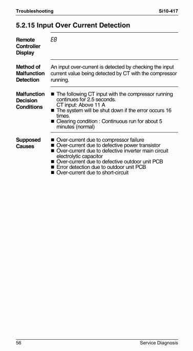
5.2.15 Input Over Current Detection
Remote Controller Display
E8
Method of Malfunction Detection
An input over-current is detected by checking the input current value being detected by CT with the compressor running.
Malfunction Decision Conditions
The following CT input with the compressor running continues for 2.5 seconds.CT input: Above 11 AThe system will be shut down if the error occurs 16 times.Clearing condition : Continuous run for about 5 minutes (normal)
Supposed Causes
Over-current due to compressor failureOver-current due to defective power transistorOver-current due to defective inverter main circuit electrolytic capacitorOver-current due to defective outdoor unit PCBError detection due to outdoor unit PCBOver-current due to short-circuit
56 Service Diagnosis

Si10-417 Troubleshooting
Si10-417.fm Page 57 Wednesday, September 22, 2004 6:38 PM
Troubleshooting
CheckNo.7-2
Refer toP.159
Check No.8Refer to
P.160
Check No.14Refer to
P.164
Note: If the model doesn’t have SPM, replace the outdoor unit PCB.
∗ An input over-current may result from wrong internal wiring. If the wires have been disconnected and reconnected for part replacement, for example, and the system is interrupted by an input over-current, take the following procedure.
Replace the outdoor unit PCB.
Replace the electrolytic capacitor.
∗ Inverter checker Part No.: 1225477
Correct the power supply or replace the SPM.(Replace the outdoor unit PCB.)
(R2844)
Inputcurrent flowing above
its stop level?
NO
YES
NONormal?
Any LED off?YES
NO
Check with the inverter checker (∗).
Turn off the power, and reconnect the harnesses. Turn on the power again and get restarted.
Turn off the power and disconnect the harnesses U, V and W.
YES
Get restarted and measure the input current.
Check No. 8Check the discharge pressure.
Check No. 7-2Check the installation condition.
Check No. 14Check the main circuit electrolytic capacitor.
CautionBe sure to turn off power switch before connect or disconnect connector, or parts damage may be occurred.
Service Diagnosis 57

Troubleshooting Si10-417
Si10-417.fm Page 58 Wednesday, September 22, 2004 6:38 PM
5.2.16 Four Way Valve Abnormality
Remote Controller Display
EA
Method of Malfunction Detection
The liquid pipe temperature thermistor, the outdoor air temperature thermistor and the outdoor unit heat exchanger thermistor are checked to see if they function within their normal ranges in the operating mode.
Malfunction Decision Conditions
A following condition occurs after 3 minutes of the compressor start.
Cooling / dry operation(outdoor unit heat exchanger temp. – liquid pipe temp.) < –5°CHeating(liquid pipe temp. – outdoor unit heat exchanger temp.) < 0°C
Supposed Causes
Connector in poor contactThermistor defectiveOutdoor unit PCB defectiveFour way valve coil or harness defectiveFour way valve defectiveForeign substance mixed in refrigerantInsufficient gas
58 Service Diagnosis

Si10-417 Troubleshooting
Si10-417.fm Page 59 Wednesday, September 22, 2004 6:38 PM
Troubleshooting
CheckNo.5-2
Refer toP.156
Check No.6Refer to
P.157
Check No.11Refer to
P.162
Correct.
Reconnect.
Replace the four way valve coil.
Replace the outdoor unit PCB.
Reconnect in position.
Replace a defective thermistor.
Refer to the refrigerant line check procedure.
Replace the four way valve (defective or dust-clogged).
(R3040)
Four wayvalve coil disconnected
(loose)?
YES
NO
NO
NO
Check No. 11Check the refrigerant line.
l Insufficient gasl Water mixedl Stop valve defective
YES
YES
Harnessout of connector?
NO
YES
Disconnectthe harness fromthe connector.
Resistance between harnesses about
3kΩ±0.5kΩ?
Malfunctioning
Malfunctioning
Malfunctioning
Functioning
Functioning
Functioning
Check No. 5-2Check the four way valve
switchingoutput.
Any thermistordisconnected?
Check No. 6Check the thermistors.
Check the continuity of the four way valve coil and harness.
CautionBe sure to turn off power switch before connect or disconnect connector, or parts damage may be occurred.
Service Diagnosis 59

Troubleshooting Si10-417
Si10-417.fm Page 60 Wednesday, September 22, 2004 6:38 PM
5.2.17 Four Way Valve Abnormality
Remote Controller Display
EA
Method of Malfunction Detection
The indoor air temperature thermistor, the indoor unit heat exchanger thermistor, the outdoor temperature thermistor and the outdoor unit heat exchanger thermistor are checked to see if they function within their normal ranges in the operating mode.
Malfunction Decision Conditions
A following condition continues over 10 minute after operating 5 minutes.
Cooling / dry operation(room temp. – indoor heat exchanger temp.) < -10°CHeating(indoor unit heat exchanger temp. – room temp.) < -10°C
Supposed Causes
Connector in poor contactThermistor defectiveOutdoor unit PCB defectiveFour way valve coil or harness defectiveFour way valve defectiveForeign substance mixed in refrigerantInsufficient gas
60 Service Diagnosis

Si10-417 Troubleshooting
Si10-417.fm Page 61 Wednesday, September 22, 2004 6:38 PM
Troubleshooting
CheckNo.5-2
Refer toP.156
Check No.6Refer to
P.157
Check No.11Refer to
P.162
Correct.
Reconnect.
Replace the four way valve coil.
Replace the outdoor unit PCB.
Reconnect in position.
Replace a defective thermistor.
Refer to the refrigerant line check procedure.
Replace the four way valve (defective or dust-clogged).
(R3040)
Four wayvalve coil disconnected
(loose)?
YES
NO
NO
NO
Check No. 11Check the refrigerant line.
l Insufficient gasl Water mixedl Stop valve defective
YES
YES
Harnessout of connector?
NO
YES
Disconnectthe harness fromthe connector.
Resistance between harnesses about
3kΩ±0.5kΩ?
Malfunctioning
Malfunctioning
Malfunctioning
Functioning
Functioning
Functioning
Check No. 5-2Check the four way valve
switchingoutput.
Any thermistordisconnected?
Check No. 6Check the thermistors.
Check the continuity of the four way valve coil and harness.
CautionBe sure to turn off power switch before connect or disconnect connector, or parts damage may be occurred.
Service Diagnosis 61

Troubleshooting Si10-417
Si10-417.fm Page 62 Wednesday, September 22, 2004 6:38 PM
5.2.18 Four Way Valve Abnormality
Remote Controller Display
EA
Method of Malfunction Detection
The room temperature thermistor, the indoor unit heat exchanger thermistor, the outdoor temperature thermistor and the outdoor unit heat exchanger thermistor are checked to see if they function within their normal ranges in the operating mode.
Malfunction Decision Conditions
A following condition continues over 1 minute after operating 10 minutes.
Cooling / dry operation(room temp. – indoor heat exchanger temp.) < –10°CHeating(indoor unit heat exchanger temp. – room temp.) < –10°C
Supposed Causes
Connector in poor contactThermistor defectiveOutdoor unit PCB defectiveFour way valve coil or harness defectiveFour way valve defectiveForeign substance mixed in refrigerantInsufficient gas
62 Service Diagnosis

Si10-417 Troubleshooting
Si10-417.fm Page 63 Wednesday, September 22, 2004 6:38 PM
Troubleshooting
CheckNo.5-1
Refer toP.155
Check No.6Refer to
P.157
Check No.11Refer to
P.162
Correct.
Reconnect.
Replace the four way valve coil.
Replace the outdoor unit PCB.
Reconnect in position.
Replace a defective thermistor.
Refer to the refrigerant line check procedure.
Replace the four way valve (defective or dust-clogged).
(R2845)
Four wayvalve coil disconnected
(loose)?
YES
NO
NO
Check No. 11Check the refrigerant
line. l Insufficient gasl Water mixedl Stop valve defective
YES
YES
NO
Harnessout of connector?
NO
YES
Disconnectthe harness from
the connector.Resistance between
harnesses about1500 Ω?
Check No. 5-1Check the four way valve
switching output.
Any thermistordisconnected?
Check No. 6Check the thermistors.
Check the continuity of the four way valve coil and harness.
Malfunctioning
Malfunctioning
Malfunctioning
Functioning
Functioning
Functioning
CautionBe sure to turn off power switch before connect or disconnect connector, or parts damage may be occurred.
Service Diagnosis 63

Troubleshooting Si10-417
Si10-417.fm Page 64 Wednesday, September 22, 2004 6:38 PM
5.2.19 Four Way Valve Abnormality
Remote Controller Display
EA
Outdoor Unit LED Display
A 5 1 4 2 1 3 1 4 1
Method of Malfunction Detection
The liquid pipe thermistor, the outdoor temperature thermistor and the outdoor unit heat exchanger thermistor are checked to see if they function within their normal ranges in the operating mode.
Malfunction Decision Conditions
Either of the following conditions occurs 3 minutes after the compressor has started.
Cooling / dry operation(Outdoor unit heat exchanger temperature – Liquid pipe temperature) < –5°CHeating operation(Liquid pipe temperature – Outdoor unit heat exchanger temperature) < –5°C
Supposed Causes
Connector in poor contactThermistor defectiveOutdoor unit PCB defectiveFour way valve coil or harness defectiveFour way valve defectiveForeign substance mixed in refrigerant
64 Service Diagnosis

Si10-417 Troubleshooting
Si10-417.fm Page 65 Wednesday, September 22, 2004 6:38 PM
Troubleshooting
CheckNo.5-1
Refer toP.155
Check No.6Refer to
P.157
Check No.11Refer to
P.162
(Q0353)
Four-way valvecoil disconnected
(loose)?
Check No. 11Check the refrigerant
line.
Harness out ofconnector?
Disconnectthe harness from
the connector. Resistance between
harnesses about 1500 Ω?
Check No. 5-1Check the four-way valve
switching output.
Any thermistordisconnected?
Check No. 6Check the thermistors.
Check the continuity of the four-way valve coil and harness.
Correct.
Reconnect.
Replace the four-way valve coil.
Replace the outdoor unit PC board.
Reconnect in position.
Replace a defective thermistor.
Refer to the refrigerant line check procedure.
Replace the four way valve (defective or dust-clogged).
YES
NO
NO
l Water mixedl Shut-off
valvedefective
YES
YES
NO
NO
YES
Malfunctioning
Malfunctioning
Malfunctioning
Functioning
Functioning
Functioning
CautionBe sure to turn off power switch before connect or disconnect connector, or parts damage may be occurred.
Service Diagnosis 65

Troubleshooting Si10-417
Si10-417.fm Page 66 Wednesday, September 22, 2004 6:38 PM
5.2.20 Discharge Pipe Temperature Control
Remote Controller Display
F3
Method of Malfunction Detection
The discharge pipe temperature control (stop, frequency drooping, etc.) is checked with the temperature being detected by the discharge pipe thermistor.
Malfunction Decision Conditions
If a stop takes place 6 times successively due to abnormal discharge pipe temperature, the system will be shut down.If the temperature being detected by the discharge pipe thermistor rises above °C, the compressor will stop. (The error is cleared when the temperature has dropped below °C.)
Stop temperatures
The error counter will reset itself if this or any other error does not occur during the following 60-minute compressor running time (total time).
Supposed Causes
Refrigerant shortageFour way valve malfunctioningDischarge pipe thermistor defective(heat exchanger or outdoor air temperature thermistor defective)Outdoor unit PCB defectiveWater mixed in the local pipingElectronic expansion valve defectiveStop valve defective
FTK(X)S, ATK(X)S series others
1. above 45Hz (rising), above 40Hz (dropping)
120 80 117 80
2. 130~45Hz (rising), 25~40Hz (dropping) 110 70 117 80
3. below 30Hz (rising), below 25Hz (dropping)
105 65 117 80
66 Service Diagnosis

Si10-417 Troubleshooting
Si10-417.fm Page 67 Wednesday, September 22, 2004 6:38 PM
Troubleshooting
Check No.4Refer to
P.151
Check No.6Refer to
P.157
Check No.11Refer to
P.162
l Discharge pipe thermistor
l Outdoor unit heat exchanger thermistor
l Outdoor temperature thermistor
l Refrigerant shortage
l Four way valve malfunc-tioning
l Water mixed
l Stop valve defective
Replace a defective thermistor.
Replace the valve itself or the coil.
Refer to the refrigerant line check procedure.
Replace the outdoor unit PCB.
(R2846)
Check No. 6Check the thermistors.
Malfunctioning
Functioning
Functioning
Functioning
Check No. 11Check the refrigerant
line.
Malfunctioning
Malfunctioning
Check No. 4Check the electronic
expansion valve.
CautionBe sure to turn off power switch before connect or disconnect connector, or parts damage may be occurred.
Service Diagnosis 67

Troubleshooting Si10-417
Si10-417.fm Page 68 Wednesday, September 22, 2004 6:38 PM
5.2.21 Discharge Pipe Temperature Control
Remote Controller Display
F3
Method of Malfunction Detection
The discharge pipe temperature control (stop, frequency drooping, etc.) is checked with the temperature being detected by the discharge pipe thermistor.
Malfunction Decision Conditions
If a stop takes place 6 times successively due to abnormal discharge pipe temperature, the system will be shut down.If the temperature being detected by the discharge pipe thermistor rises above 120°C, the compressor will stop. (The error is cleared when the temperature has dropped below 107°C.)
Stop temperatures (in case of 5.0kW class)(1) 110°C : above 45Hz (rising), above 40Hz (dropping)(2) 102°C : 30~45Hz (rising), 25~40Hz (dropping)(3) 98°C : below 30Hz (rising), below 25Hz (dropping)
The error counter will reset itself if this or any other error does not occur during the following 60-minute compressor running time (total time).
Supposed Causes
Refrigerant shortageFour way valve malfunctioningDischarge pipe thermistor defective(heat exchanger or outdoor temperature thermistor defective)Outdoor unit PCB defectiveWater mixed in the local pipingElectronic expansion valve defectiveStop valve defective
68 Service Diagnosis

Si10-417 Troubleshooting
Si10-417.fm Page 69 Wednesday, September 22, 2004 6:38 PM
Troubleshooting
Check No.4Refer to
P.151
Check No.6Refer to
P.157
Check No.11Refer to
P.162
l Discharge pipe thermistor
l Outdoor unit heat exchanger thermistor
l Outdoor temperature thermistor
l Refrigerant shortage
l Four way valve malfunc-tioning
l Water mixed
l Stop valve defective
Replace a defective thermistor.
Replace the valve itself or the coil.
Refer to the refrigerant line check procedure.
Replace the outdoor unit PCB.
(R2846)
Check No. 6Check the thermistors.
Malfunctioning
Functioning
Functioning
Functioning
Check No. 11Check the refrigerant
line.
Malfunctioning
Malfunctioning
Check No. 4Check the electronic
expansion valve.
CautionBe sure to turn off power switch before connect or disconnect connector, or parts damage may be occurred.
Service Diagnosis 69

Troubleshooting Si10-417
Si10-417.fm Page 70 Wednesday, September 22, 2004 6:38 PM
5.2.22 Discharge Pipe Temperature Control
Remote Controller Display
F3
Outdoor Unit LED Display
A 5 1 4 2 1 3 4 4 1
Method of Malfunction Detection
The discharge pipe temperature control (stop, frequency drooping, etc.) is checked with the temperature being detected by the discharge pipe thermistor.
Malfunction Decision Conditions
If a stop takes place 6 times straight due to abnormal discharge pipe temperature, the system will be shut down.If the temperature being detected by the discharge pipe thermistor rises above 120°C, the compressor will stop. (The error is cleared when the temperature has dropped below 107°C.)
Stop temperatures (in the case of 3MXS52BVMB)(1) 110°C when the frequency rises above 45 Hz or
drops below 40 Hz.(2) 102°C when the frequency rises from 30 Hz to 45 Hz
or drops from 40 Hz to 25 Hz.(3) 98°C when the frequency rises just up to 30 Hz or
drops below 25 Hz.The error counter will reset itself if this or any other error does not occur during the following 60-minute compressor running time (total time).
Supposed Causes
Refrigerant shortageFour way valve malfunctioningDischarge pipe thermistor defective(heat exchanger or outdoor temperature thermistor defective)Outdoor unit PCB defectiveWater mixed in the local pipingElectronic expansion valve defectiveStop valve defective
70 Service Diagnosis

Si10-417 Troubleshooting
Si10-417.fm Page 71 Wednesday, September 22, 2004 6:38 PM
Troubleshooting
Check No.4Refer to
P.151
Check No.6Refer to
P.157
Check No.11Refer to
P.162
l Discharge pipe thermistor
l Outdoor unit heat exchanger thermistor
l Outdoor temperature thermistor
l Refrigerant shortage
l Four way valve malfunc-tioning
l Water mixed
l Stop valve defective
Replace a defective thermistor.
Replace the valve itself or the coil.
Refer to the refrigerant line check procedure.
Replace the outdoor unit PCB.
(R2846)
Check No. 6Check the thermistors.
Malfunctioning
Functioning
Functioning
Functioning
Check No. 11Check the refrigerant
line.
Malfunctioning
Malfunctioning
Check No. 4Check the electronic
expansion valve.
CautionBe sure to turn off power switch before connect or disconnect connector, or parts damage may be occurred.
Service Diagnosis 71

Troubleshooting Si10-417
Si10-417.fm Page 72 Wednesday, September 22, 2004 6:38 PM
5.2.23 Discharge Pipe Temperature Control
Remote Controller Display
F3
Method of Malfunction Detection
The discharge pipe temperature control (stop, frequency drooping, etc.) is checked with the temperature being detected by the discharge pipe thermistor.
Malfunction Decision Conditions
If a stop takes place 6 times successively due to abnormal discharge pipe temperature, the system will be shut down.If the temperature being detected by the discharge pipe thermistor rises above 110°C, the compressor will stop. (The error is cleared when the temperature has dropped below 97°C.)
Stop temperatures(1) 110°C : above 45Hz (rising), above 40Hz (dropping)(2) 102°C : 30~45Hz (rising), 25~40Hz (dropping)(3) 98°C : below 30Hz (rising), below 25Hz (dropping)
The error counter will reset itself if this or any other error does not occur during the following 60-minute compressor running time (total time).
Supposed Causes
Refrigerant shortageFour way valve malfunctioningDischarge pipe thermistor defective(heat exchanger or outdoor air temperature thermistor defective)Outdoor unit PCB defectiveWater mixed in the local pipingElectronic expansion valve defectiveStop valve defective
72 Service Diagnosis

Si10-417 Troubleshooting
Si10-417.fm Page 73 Wednesday, September 22, 2004 6:38 PM
Troubleshooting
Check No.4Refer to
P.151
Check No.6Refer to
P.157
Check No.11Refer to
P.162
l Discharge pipe thermistor
l Outdoor unit heat exchanger thermistor
l Outdoor temperature thermistor
l Refrigerant shortage
l Four way valve malfunc-tioning
l Water mixed
l Stop valve defective
Replace a defective thermistor.
Replace the valve itself or the coil.
Refer to the refrigerant line check procedure.
Replace the outdoor unit PCB.
(R2846)
Check No. 6Check the thermistors.
Malfunctioning
Functioning
Functioning
Functioning
Check No. 11Check the refrigerant
line.
Malfunctioning
Malfunctioning
Check No. 4Check the electronic
expansion valve.
CautionBe sure to turn off power switch before connect or disconnect connector, or parts damage may be occurred.
Service Diagnosis 73

Troubleshooting Si10-417
Si10-417.fm Page 74 Wednesday, September 22, 2004 6:38 PM
5.2.24 High Pressure Control in Cooling
Remote Controller Display
F6
Method of Malfunction Detection
High-pressure control (stop, frequency drop, etc.) is activated in the cooling mode if the temperature being sensed by the heat exchanger thermistor exceeds the limit.
Malfunction Decision Conditions
Activated when the temperature being sensed by the heat exchanger thermistor rises above 60°C. (Deactivated when the said temperature drops below 50°C.)
Supposed Causes
The installation space is not large enough.Faulty outdoor unit fanFaulty electronic expansion valveFaulty defrost thermistorFaulty outdoor unit PCBFaulty stop valveDirty heat exchanger
Troubleshooting
Check No.4Refer to
P.151
Check No.6Refer to
P.157
CheckNo.7-1
Refer toP.158
Check No.9Refer to
P.160
(R2855)
Replace the fan motor.Repair the connector or fan motor lead wires.
Replace the heat exchanger thermistor.
Replace PCB.
Replace the electronic expansion valve or coil.Replace the PCB.
Change the air outlet grille position.Change the installation location.Clean the heat exchanger.
Check the installation space.
Check No.9Outdoor fan check
Judgment
Check No.6Heat exchanger thermistor check
Judgment
Check No.7-1Installation condition
check
Check No.4Electronic expansion valve check
Abnormal
Normal
Normal
Normal
Normal
Abnormal
Abnormal
Abnormal
CautionBe sure to turn off power switch before connect or disconnect connector, or parts damage may be occurred.
74 Service Diagnosis
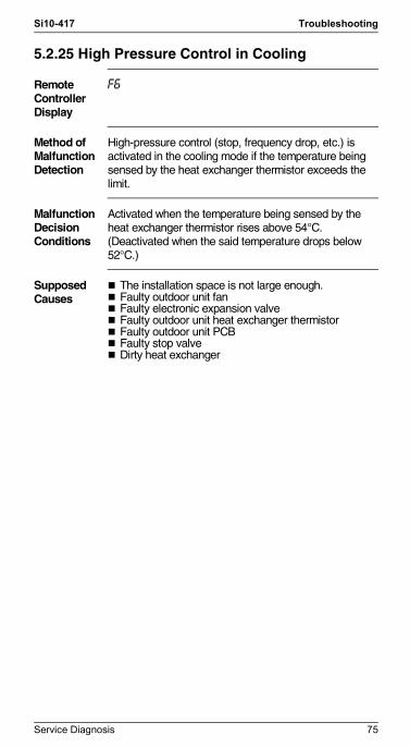
Si10-417 Troubleshooting
Si10-417.fm Page 75 Wednesday, September 22, 2004 6:38 PM
5.2.25 High Pressure Control in Cooling
Remote Controller Display
F6
Method of Malfunction Detection
High-pressure control (stop, frequency drop, etc.) is activated in the cooling mode if the temperature being sensed by the heat exchanger thermistor exceeds the limit.
Malfunction Decision Conditions
Activated when the temperature being sensed by the heat exchanger thermistor rises above 54°C. (Deactivated when the said temperature drops below 52°C.)
Supposed Causes
The installation space is not large enough.Faulty outdoor unit fanFaulty electronic expansion valveFaulty outdoor unit heat exchanger thermistorFaulty outdoor unit PCBFaulty stop valveDirty heat exchanger
Service Diagnosis 75

Troubleshooting Si10-417
Si10-417.fm Page 76 Wednesday, September 22, 2004 6:38 PM
Troubleshooting
Check No.4Refer to
P.151
Check No.6Refer to
P.157
CheckNo.7-2
Refer toP.159
Check No.9Refer to
P.160
(R2855)
Replace the fan motor.Repair the connector or fan motor lead wires.
Replace the heat exchanger thermistor.
Replace PCB.
Replace the electronic expansion valve or coil.Replace the PCB.
Change the air outlet grille position.Change the installation location.Clean the heat exchanger.
Check the installation space.
Check No.9Outdoor fan check
Judgment
Check No.6Heat exchanger thermistor check
Judgment
Check No.7-2Installation condition
check
Check No.4Electronic expansion valve check
Abnormal
Normal
Normal
Normal
Normal
Abnormal
Abnormal
Abnormal
CautionBe sure to turn off power switch before connect or disconnect connector, or parts damage may be occurred.
76 Service Diagnosis

Si10-417 Troubleshooting
Si10-417.fm Page 77 Wednesday, September 22, 2004 6:38 PM
5.2.26 Position Sensor Abnormality
Remote Controller Display
H6
Method of Malfunction Detection
FTK(X)S, ATK(X)S series onlyA compressor startup failure is detected by checking the compressor running condition through the position detection circuit.
Malfunction Decision Conditions
The compressor fails to start in about 15 seconds after the compressor run command signal is sent.Clearing condition: Continuous run for about 5 minutes (normal)The system will be shut down if the error occurs 16 times.
Supposed Causes
Compressor relay cable disconnectedCompressor itself defectiveOutdoor unit PCB defectiveStop valve closedInput voltage out of specification
Service Diagnosis 77

Troubleshooting Si10-417
Si10-417.fm Page 78 Wednesday, September 22, 2004 6:38 PM
Troubleshooting
Check No.13Refer to
P.163 Replace the outdoor unit PCB.
Replace the outdoor unit PCB.
Reconnect as specified.
∗ Inverter checker Part No.: 1225477
Correct the power supply or replace the outdoor unit PCB.
Replace the compressor.
(R3041)
NormalNO
NO
YES
YES
NO
YES
YES
Any LED off?
NO
DC290~380V?
Electricalsor compressor harnesses
connected asspecified?
Check the electrolytic capacitor voltage.
Check with the inverter checker (∗).
Turn off the power. Disconnect the harnesses U, V and W.
Check No. 13Check for short-circuit.
CautionBe sure to turn off power switch before connect or disconnect connector, or parts damage may be occurred.
78 Service Diagnosis

Si10-417 Troubleshooting
Si10-417.fm Page 79 Wednesday, September 22, 2004 6:38 PM
5.2.27 Position Sensor Abnormality
Remote Controller Display
H6
Method of Malfunction Detection
A compressor startup failure is detected by checking the compressor running condition through the position detection circuit.
Malfunction Decision Conditions
The compressor fails to start in about 15 seconds after the compressor run command signal is sent.Clearing condition: Continuous run for about 5 minutes (normal)The system will be shut down if the error occurs 16 times.
Supposed Causes
Compressor relay cable disconnectedCompressor itself defectiveOutdoor unit PCB defectiveStop valve closedInput voltage out of specification
Service Diagnosis 79
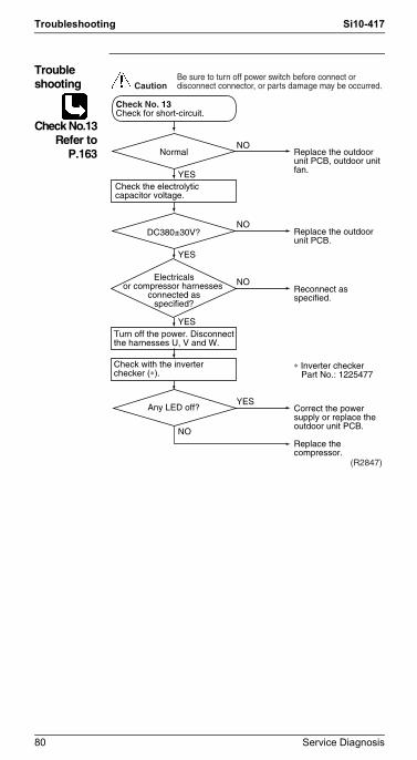
Troubleshooting Si10-417
Si10-417.fm Page 80 Wednesday, September 22, 2004 6:38 PM
Troubleshooting
Check No.13Refer to
P.163 Replace the outdoor unit PCB, outdoor unit fan.
Replace the outdoor unit PCB.
Reconnect as specified.
∗ Inverter checker Part No.: 1225477
Correct the power supply or replace the outdoor unit PCB.
Replace the compressor.
(R2847)
NormalNO
NO
YES
YES
NO
YES
YES
Any LED off?
NO
DC380±30V?
Electricalsor compressor harnesses
connected asspecified?
Check the electrolytic capacitor voltage.
Check with the inverter checker (∗).
Turn off the power. Disconnect the harnesses U, V and W.
Check No. 13Check for short-circuit.
CautionBe sure to turn off power switch before connect or disconnect connector, or parts damage may be occurred.
80 Service Diagnosis

Si10-417 Troubleshooting
Si10-417.fm Page 81 Wednesday, September 22, 2004 6:38 PM
5.2.28 Position Sensor Abnormality
Remote Controller Display
H6
Outdoor Unit LED Display
A 5 1 4 2 4 3 1 4 1
Method of Malfunction Detection
A compressor startup failure is detected by checking the compressor running condition through the position detection circuit.
Malfunction Decision Conditions
The compressor fails to start in about 15 seconds after the compressor run command signal is sent.Clearing condition: Continuous run for about 5 minutes (normal)The system will be shut down if the error occurs 16 times.
Supposed Causes
Compressor relay cable disconnectedCompressor itself defectiveOutdoor unit PCB defectiveStop valve closedInput voltage out of specification
Service Diagnosis 81

Troubleshooting Si10-417
Si10-417.fm Page 82 Wednesday, September 22, 2004 6:38 PM
Troubleshooting
Check No.13Refer to
P.163 Replace the outdoor unit PCB, outdoor unit fan.
Replace the outdoor unit PCB.
Reconnect as specified.
∗ Inverter checker Part No.: 1225477
Correct the power supply or replace the outdoor unit PCB.
Replace the compressor.
(R2847)
NormalNO
NO
YES
YES
NO
YES
YES
Any LED off?
NO
DC380±30V?
Electricalsor compressor harnesses
connected asspecified?
Check the electrolytic capacitor voltage.
Check with the inverter checker (∗).
Turn off the power. Disconnect the harnesses U, V and W.
Check No. 13Check for short-circuit.
CautionBe sure to turn off power switch before connect or disconnect connector, or parts damage may be occurred.
82 Service Diagnosis

Si10-417 Troubleshooting
Si10-417.fm Page 83 Wednesday, September 22, 2004 6:38 PM
5.2.29 Position Sensor Abnormality
Remote Controller Display
H6
Method of Malfunction Detection
A compressor startup failure is detected by checking the compressor running condition through the position detection circuit.
Malfunction Decision Conditions
The compressor is not running in about 15 seconds after the compressor run command signal is sent.Clearing condition: Continuous run for about 5 minutes (normal)The system will be shut down if the error occurs 8 times.
Supposed Causes
Compressor relay cable disconnectedCompressor itself defectiveOutdoor unit PCB defectiveStop valve closedInput voltage out of specification
Service Diagnosis 83

Troubleshooting Si10-417
Si10-417.fm Page 84 Wednesday, September 22, 2004 6:38 PM
Troubleshooting
Check No.13Refer to
P.163 Replace the outdoor unit PCB.
Replace the outdoor unit PCB.
Reconnect as specified.
∗ Inverter checker Part No.: 1225477
Correct the power supply or replace the outdoor unit PCB.
Replace the compressor.
(R3041)
NormalNO
YES
NO
YES
Any LED off?
NO
NO
YES
DC290~380V?
Check the electrolytic capacitor voltage.
Check with the inverter checker (∗).
Turn off the power. Disconnect the harnesses U, V and W.
Check No. 13Check for short-circuit.
Electricals orcompressor harnesses
connected asspecified?
YES
CautionBe sure to turn off power switch before connect or disconnect connector, or parts damage may be occurred.
84 Service Diagnosis

Si10-417 Troubleshooting
Si10-417.fm Page 85 Wednesday, September 22, 2004 6:38 PM
5.2.30 CT or Related Abnormality
Remote Controller Display
H8
Method of Malfunction Detection
A CT or related error is detected by checking the compressor running frequency and CT-detected input current.
Malfunction Decision Conditions
The compressor running frequency is below 62 Hz and the CT input is below 0.1 V.(The input current is also below 0.5 A.)
If this error repeats 4 times, the system will be shut down.The error counter will reset itself if this or any other error does not occur during the following 60-minute compressor running time (total time).
Supposed Causes
Power transistor defectiveInternal wiring broken or in poor contactReactor defectiveOutdoor unit PCB defective
Troubleshooting
Check No.12Refer to
P.163
Turn off the power and turn it on again.
Check No. 12Check the capacitor voltage.
Replace the outdoor unit PCB.
Replace the outdoor unit PCB.
Check the supply voltage.
YES
NO
∗ Runningcurrent as shown at right
with relay cable1 or 2?
NO
DC290~380V?YES
Voltagewithin the allowable
range (Supplyvoltage±15%)?
NO
YES
Get the system started.
Measure the rectifier input voltage.
A
Rising with increasingfrequency
2 sec Time
Capacitor charged when the indoor unit or outdoor unit main relay turns on
Current (guideline)
CautionBe sure to turn off power switch before connect or disconnect connector, or parts damage may be occurred.
Service Diagnosis 85

Troubleshooting Si10-417
Si10-417.fm Page 86 Wednesday, September 22, 2004 6:38 PM
Note: If the model doesn’t have SPM, replace the outdoor unit PCB.
* Inverter checker Part No.: 1225477
Correct the power supply or replace the SPM.(Replace the outdoor unit PCB.)
Replace the outdoor unit PCB.
Replace the compressor.
Any LED off?
Compressor running?
NO
YES
YES
NO
Turn off the power. Disconnect the harnesses U, V and W.
Turn off the power and reconnect the above harnesses. Then turn on the power again and get the system restarted.
A
(R3042)
Check with the inverter checker (∗).
86 Service Diagnosis

Si10-417 Troubleshooting
Si10-417.fm Page 87 Wednesday, September 22, 2004 6:38 PM
5.2.31 CT or Related Abnormality
Remote Controller Display
H8
Method of Malfunction Detection
A CT or related error is detected by checking the compressor running frequency and CT-detected input current.
Malfunction Decision Conditions
The compressor running frequency is below 55 Hz and the CT input is below 0.1 V.(The input current is also below 1.25 A.)
If this error repeats 4 times, the system will be shut down.The error counter will reset itself if this or any other error does not occur during the following 60-minute compressor running time (total time).
Supposed Causes
Power transistor defectiveInternal wiring broken or in poor contactReactor defectiveOutdoor unit PCB defective
Troubleshooting
Check No.12Refer to
P.163
Turn off the power and turn it on again.
Check No. 12Check the capacitor voltage.
Replace the outdoor unit PCB.
Replace the outdoor unit PCB.
Check the supply voltage.
YES
NO
∗ Runningcurrent as shown at right
with relay cable1 or 2?
NO
YES
Voltagewithin the allowable
range (Supplyvoltage±15%)?
NO
YES
Get the system started.
Measure the rectifier input voltage.
A
Rising with increasingfrequency
2 sec Time
Capacitor charged when the indoor unit or outdoor unit main relay turns on
CautionBe sure to turn off power switch before connect or disconnect connector, or parts damage may be occurred.
DC380±30V?
Current (guideline)
Service Diagnosis 87

Troubleshooting Si10-417
Si10-417.fm Page 88 Wednesday, September 22, 2004 6:38 PM
* Inverter checker Part No.: 1225477
Correct the power supply or replace the SPM.(Replace the outdoor unit PCB.)
Replace the outdoor unit PCB.
Replace the compressor.
Any LED off?
Compressor running?
NO
YES
YES
NO
Turn off the power. Disconnect the harnesses U, V and W.
Turn off the power and reconnect the above harnesses. Then turn on the power again and get the system restarted.
A
Check with the inverter checker (∗).
(R2848)
88 Service Diagnosis

Si10-417 Troubleshooting
Si10-417.fm Page 89 Wednesday, September 22, 2004 6:38 PM
5.2.32 CT or Related Abnormality
Remote Controller Display
H8
Outdoor Unit LED Display
A 5 1 4 2 4 3 1 4 1
Method of Malfunction Detection
A CT or related error is detected by checking the compressor running frequency and CT-detected input current.
Malfunction Decision Conditions
The compressor running frequency is below 55 Hz and the CT input is below 0.1 V.(The input current is also below 1.25 A.)
If this error repeats 4 times, the system will be shut down.The error counter will reset itself if this or any other error does not occur during the following 60-minute compressor running time (total time).
Supposed Causes
Power transistor defectiveInternal wiring broken or in poor contactReactor defectiveOutdoor unit PCB defective
Service Diagnosis 89

Troubleshooting Si10-417
Si10-417.fm Page 90 Wednesday, September 22, 2004 6:38 PM
Troubleshooting
Check No.12Refer to
P.163
Turn off the power and turn it on again.
Check No. 12Check the capacitor voltage.
Replace the outdoor unit PCB.
Replace the outdoor unit PCB.
Check the supply voltage.
YES
NO
∗ Runningcurrent as shown at right
with relay cable1 or 2?
NO
YES
Voltagewithin the allowable
range (Supplyvoltage±15%)?
NO
YES
Get the system started.
Measure the rectifier input voltage.
A
Rising with increasingfrequency
2 sec Time
Capacitor charged when the indoor unit or outdoor unit main relay turns on
CautionBe sure to turn off power switch before connect or disconnect connector, or parts damage may be occurred.
DC380±30V?
Current (guideline)
* Inverter checker Part No.: 1225477
Correct the power supply or replace the SPM.(Replace the outdoor unit PCB.)
Replace the outdoor unit PCB.
Replace the compressor.
Any LED off?
Compressor running?
NO
YES
YES
NO
Turn off the power. Disconnect the harnesses U, V and W.
Turn off the power and reconnect the above harnesses. Then turn on the power again and get the system restarted.
A
Check with the inverter checker (∗).
(R2848)
90 Service Diagnosis

Si10-417 Troubleshooting
Si10-417.fm Page 91 Wednesday, September 22, 2004 6:38 PM
5.2.33 CT or Related Abnormality
Remote Controller Display
H8
Method of Malfunction Detection
A CT or related error is detected by checking the compressor running frequency and CT-detected input current.
Malfunction Decision Conditions
The compressor running frequency is above 68 Hz and the CT input is below 0.1 V.(The input current is also below 1.25 A.)
If this error repeats 4 times, the system will be shut down.The error counter will reset itself if this or any other error does not occur during the following 60-minute compressor running time (total time).
Supposed Causes
Power transistor defectiveInternal wiring broken or in poor contactReactor defectiveOutdoor unit PCB defective
Troubleshooting
Check No.12Refer to
P.163
DC290~380V?
Turn off the power and turn it on again.
Check No. 12Check the capacitor voltage.
Replace the outdoor unit PCB.
Replace the outdoor unit PCB.
Check the supply voltage.
YES
NO
∗ Runningcurrent as shown at right
with relay cable1 or 2?
NO
YES
Voltagewithin the allowable
range (Supplyvoltage±15%)?
NO
YES
Get the system started.
Measure the rectifier input voltage.
A
Rising with increasingfrequency
2 sec Time
Capacitor charged when the indoor unit or outdoor unit main relay turns on
CautionBe sure to turn off power switch before connect or disconnect connector, or parts damage may be occurred.
Current (guideline)
Service Diagnosis 91

Troubleshooting Si10-417
Si10-417.fm Page 92 Wednesday, September 22, 2004 6:38 PM
Note: If the model doesn’t have SPM, replace the outdoor unit PCB.
(R3042)
* Inverter checker Part No.: 1225477
Correct the power supply or replace the SPM.(Replace the outdoor unit PCB.)
Replace the outdoor unit PCB.
Replace the compressor.
Any LED off?
Compressor running?
NO
YES
YES
NO
Turn off the power. Disconnect the harnesses U, V and W.
Turn off the power and reconnect the above harnesses. Then turn on the power again and get the system restarted.
A
Check with the inverter checker (∗).
92 Service Diagnosis

Si10-417 Troubleshooting
Si10-417.fm Page 93 Wednesday, September 22, 2004 6:38 PM
5.2.34 Thermistor or Related Abnormality (Outdoor Unit)
Remote Controller Display
P4, J3, J6, H9
Method of Malfunction Detection
This type of error is detected by checking the thermistor input voltage to the microcomputer.[A thermistor error is detected by checking the temperature.]
Malfunction Decision Conditions
The thermistor input is above 4.96 V or below 0.04 V with the power on.Error J3 is judged if the discharge pipe thermistor temperature is smaller than the condenser thermistor temperature.
Supposed Causes
Connector in poor contactThermistor defectiveOutdoor unit PCB defectiveIndoor unit PCB defectiveCondenser thermistor defective in the case of J3 error (outdoor unit heat exchanger thermistor in the cooling mode, or indoor unit heat exchanger thermistor in the heating mode)
Service Diagnosis 93

Troubleshooting Si10-417
Si10-417.fm Page 94 Wednesday, September 22, 2004 6:38 PM
Troubleshooting
Check No.6Refer to
P.157
P4 : Radiation fin thermistorJ3 : Discharge pipe thermistorJ6 : Outdoor heat exchanger thermistorH9 : Outdoor air thermistor
Turn on the power again.
(R2849)
Reconnect.
Reconnect.
Replace defective one(s) of the following thermistors.l Radiation fin
thermistorl Discharge pipe
temperature thermistor
l Outdoor unit heat exchanger temperature thermistor
l Outdoor air thermistor
Replace the following thermistor.l Indoor unit heat
exchanger thermistor
Replace the outdoor unit PCB. (Replace the indoor unit PCB.)
Errordisplayed again on remote
controller?
NO
YES
YES
YES
NO
Indoor unit heat exchanger thermistor
functioning?
Connectoror thermistor
disconnected?
NO
NO
YES
Normal?
Check No. 6Check the thermistor resistance value.
Check No. 6Check the indoor unit heat exchanger thermistor resistance value in theheating mode.
CautionBe sure to turn off power switch before connect or disconnect connector, or parts damage may be occurred.
94 Service Diagnosis

Si10-417 Troubleshooting
Si10-417.fm Page 95 Wednesday, September 22, 2004 6:38 PM
5.2.35 Thermistor or Related Abnormality (Outdoor Unit)
Remote Controller Display
P4, J3, J6, J8, J9, H9
Outdoor Unit LED Display
A 5 1 4 2 4 3 1 4 1
Method of Malfunction Detection
This type of error is detected by checking the thermistor input voltage to the microcomputer.[A thermistor error is detected by checking the temperature being detected by each thermistor.]
Malfunction Decision Conditions
When the thermistor input is above 4.96 V or below 0.04 V with the power on, the J3 error is judged if the discharge pipe thermistor temperature is smaller than the condenser thermistor temperature, or the system will be shut down if all the units are judged with the J8 error.
Supposed Causes
Connector in poor contactThermistor defectiveOutdoor unit PCB defectiveIndoor unit PCB defectiveCondenser thermistor defective in the case of J3 error (outdoor unit heat exchanger thermistor in the cooling mode, or indoor unit heat exchanger thermistor in the heating mode)
Service Diagnosis 95

Troubleshooting Si10-417
Si10-417.fm Page 96 Wednesday, September 22, 2004 6:38 PM
Troubleshooting
Check No.6Refer to
P.157
P4 : Radiation fin thermistorJ3 : Discharge pipe temperature thermistorJ6 : Outdoor unit heat exchanger temperature thermistorJ8 : Liquid pipe thermistorJ9 : Gas pipe thermistorH9 : Outdoor temperature thermistor
(Q0357)
J3 error if discharge pipe thermistor temperature is smaller than condenser thermistor temperature
Cooling: Outdoor unit heat exchanger thermistorHeating: Indoor unit heat exchanger thermistor
Turn on the power again.
Reconnect.
Reconnect.
Replace defective one(s) of the following thermistors.l Radiation fin
thermistorl Discharge pipe
temperature thermistor
l Outdoor unit heat exchanger temperature thermistor
l Liquid pipe thermistor
l Gas pipe thermistorl Outdoor temperature
thermistor
Replace the following thermistor.l Indoor unit heat
exchanger thermistor
Replace the outdoor unit PC board. (Replace the indoor unit PC board.)
Errordisplayed again on remote
controller?
NO
YES
YES
YES
NO
Indoor unit heat exchanger thermistor
functioning?
Connectoror thermistor
disconnected?
NO
NO
YES
Normal?
Check No. 6Check the thermistor resistance value.
Check No. 6Check the indoor unit heat exchanger thermistor resistance value in theheating mode.
CautionBe sure to turn off power switch before connect or disconnect connector, or parts damage may be occurred.
96 Service Diagnosis

Si10-417 Troubleshooting
Si10-417.fm Page 97 Wednesday, September 22, 2004 6:38 PM
5.2.36 Thermistor or Related Abnormality (Outdoor Unit)
Remote Controller Display
P4,J3,J6,J8,J9,H9
Method of Malfunction Detection
This type of error is detected by checking the thermistor input voltage to the microcomputer.[A thermistor error is detected by checking the temperature.]
Malfunction Decision Conditions
The thermistor input is above 4.96 V or below 0.04 V with the power on.Error J3 is judged if the discharge pipe thermistor temperature is smaller than the condenser thermistor temperature.In case of J8 or J9, the system will be shut down when the error is detected at all of operating units.
Supposed Causes
Connector in poor contactThermistor defectiveOutdoor unit PCB defectiveIndoor unit PCB defectiveCondenser thermistor defective in the case of J3 error (outdoor unit heat exchanger thermistor in the cooling mode, or indoor unit heat exchanger thermistor in the heating mode)
Service Diagnosis 97

Troubleshooting Si10-417
Si10-417.fm Page 98 Wednesday, September 22, 2004 6:38 PM
Troubleshooting
Check No.6Refer to
P.157
P4 : Radiation fin thermistorJ3 : Discharge pipe temperature thermistorJ6 : Outdoor unit heat exchanger temperature thermistorJ8 : Liquid pipe temperature thermistorJ9 : Gas pipe temperature thermistorH9 : Outdoor air temperature thermistor
Turn on the power again.
Errordisplayed again on remote
controller?
NO
YES
YES
YES
NO
Indoor unit heat exchanger thermistor
functioning?
Connectoror thermistor
disconnected?
NO
NO
YES
Normal?
Check No. 6Check the thermistor resistance value.
Check No. 6Check the indoor unit heat exchanger thermistor resistance value in the heating mode.
CautionBe sure to turn off power switch before connect or disconnect connector, or parts damage may be occurred.
(R3043)
Reconnect.
Reconnect.
Replace defective one(s) of the following thermistors.l Radiation fin
thermistorl Discharge pipe
temperature thermistor
l Outdoor unit heat exchanger temperature thermistor
l Liquid pipe thermistor
l Gas pipe thermistorl Outdoor temperature
thermistor
Replace the following thermistor.l Indoor unit heat
exchanger thermistor
Replace the outdoor unit PCB. (Replace the indoor unit PCB.)
98 Service Diagnosis

Si10-417 Troubleshooting
Si10-417.fm Page 99 Wednesday, September 22, 2004 6:38 PM
5.2.37 Electrical Box Temperature Rise
Remote Controller Display
L3
Method of Malfunction Detection
An electrical box temperature rise is detected by checking the radiation fin thermistor with the compressor off.
Malfunction Decision Conditions
With the compressor off, the radiation fin temperature is above 122°C. (Reset is made when the temperature drops below 113°C.)
Supposed Causes
Fin temperature rise due to defective outdoor unit fanFin temperature rise due to short-circuitFin thermistor defectiveConnector in poor contactOutdoor unit PCB defective
Troubleshooting
Check No.6Refer to
P.157
CheckNo.7-1
Refer toP.158
Check No.9Refer to
P.160
Turn off the power and turn it on again.
Replace the fan motor.Correct the connectors and fan motor leads.Replace the outdoor unit PCB.
Clean up the radiation fin.
Erroragain or outdoor unit fan
activated?
YES
NO
Slightly dirty
Check No. 9Check the outdoor unit
fan or related.
Malfunctioning
Radiation fin dirty?Too dirty
Functioning
Check No. 7-1Check the installation condition.
To cool down the electricals, the outdoor unit fan gets started when the radiation fin temperature rises above 120˚C and stops itself when it drops below 113˚C.
A
B
WARNING
CautionBe sure to turn off power switch before connect or disconnect connector, or parts damage may be occurred.
Service Diagnosis 99
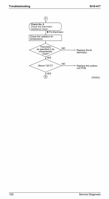
Troubleshooting Si10-417
Si10-417.fm Page 100 Wednesday, September 22, 2004 6:38 PM
(R2953)
Check No. 6Check the thermistor resistance value.
Replace the fin thermistor.
Replace the outdoor unit PCB.
l Fin thermistor
Thermistoras specified in its
characteristicchart?
Above 122˚C?
YES
NO
NO
YES
Check the radiation fin temperature.
A
B
100 Service Diagnosis

Si10-417 Troubleshooting
Si10-417.fm Page 101 Wednesday, September 22, 2004 6:38 PM
5.2.38 Electrical Box Temperature Rise
Remote Controller Display
L3
Method of Malfunction Detection
An electrical box temperature rise is detected by checking the radiation fin thermistor with the compressor off.
Malfunction Decision Conditions
With the compressor off, the radiation fin temperature is above 80°C (above 75°C in the case of 7.1kW class). (Reset is made when the temperature drops below 70°C.)
Supposed Causes
Fin temperature rise due to defective outdoor unit fanFin temperature rise due to short-circuitFin thermistor defectiveConnector in poor contactOutdoor unit PCB defective
Troubleshooting
Check No.6Refer to
P.157
CheckNo.7-1
Refer toP.158
Check No.9Refer to
P.160
Turn off the power and turn it on again.
Replace the fan motor.Correct the connectors and fan motor leads.Replace the outdoor unit PCB.
Clean up the radiation fin.
Erroragain or outdoor unit fan
activated?
YES
NO
Slightly dirty
Check No. 9Check the outdoor unit
fan or related.
Malfunctioning
Radiation fin dirty?Too dirty
Functioning
Check No. 7-1Check the installation condition.
To cool down the electricals, the outdoor unit fan gets started when the radiation fin temperature rises above 78˚C and stops itself when it drops below 70˚C.
A
B
WARNING
CautionBe sure to turn off power switch before connect or disconnect connector, or parts damage may be occurred.
Service Diagnosis 101

Troubleshooting Si10-417
Si10-417.fm Page 102 Wednesday, September 22, 2004 6:38 PM
(R2850)
Check No. 6Check the thermistor resistance value.
Replace the fin thermistor.
Replace the outdoor unit PCB.
l Fin thermistor
Thermistoras specified in its
characteristicchart?
Above 80˚C?
YES
NO
NO
YES
Check the radiation fin temperature.
A
B
102 Service Diagnosis

Si10-417 Troubleshooting
Si10-417.fm Page 103 Wednesday, September 22, 2004 6:38 PM
5.2.39 Electrical Box Temperature Rise
Remote Controller Display
L3
Outdoor Unit LED Display
A 5 1 4 2 4 3 1 4 4
Method of Malfunction Detection
An electrical box temperature rise is detected by checking the radiation fin thermistor with the compressor off.
Malfunction Decision Conditions
With the compressor off, the radiation fin temperature is above 80°C (above 75°C in the case of 8.0 · 9.0kW class). (Reset is made when the temperature drops below 70°C.)
Supposed Causes
Fin temperature rise due to defective outdoor unit fanFin temperature rise due to short-circuitFin thermistor defectiveConnector in poor contactOutdoor unit PCB defective
Troubleshooting
Check No.6Refer to
P.157
CheckNo.7-1
Refer toP.158
Check No.9Refer to
P.160
Turn off the power and turn it on again.
Replace the fan motor.Correct the connectors and fan motor leads.Replace the outdoor unit PCB.
Clean up the radiation fin.
Erroragain or outdoor unit fan
activated?
YES
NO
Slightly dirty
Check No. 9Check the outdoor unit
fan or related.
Malfunctioning
Radiation fin dirty?Too dirty
Functioning
Check No. 7-1Check the installation condition.
To cool down the electricals, the outdoor unit fan gets started when the radiation fin temperature rises above 78˚C and stops itself when it drops below 70˚C.
A
B
WARNING
CautionBe sure to turn off power switch before connect or disconnect connector, or parts damage may be occurred.
Service Diagnosis 103

Troubleshooting Si10-417
Si10-417.fm Page 104 Wednesday, September 22, 2004 6:38 PM
(R2850)
Check No. 6Check the thermistor resistance value.
Replace the fin thermistor.
Replace the outdoor unit PCB.
l Fin thermistor
Thermistoras specified in its
characteristicchart?
Above 90˚C?
YES
NO
NO
YES
Check the radiation fin temperature.
A
B
104 Service Diagnosis

Si10-417 Troubleshooting
Si10-417.fm Page 105 Wednesday, September 22, 2004 6:38 PM
5.2.40 Electrical Box Temperature Rise
Remote Controller Display
L3
Method of Malfunction Detection
An electrical box temperature rise is detected by checking the radiation fin thermistor with the compressor off.
Malfunction Decision Conditions
With the compressor off, the radiation fin temperature is above 80°C (above 75°C in the case of 7.1kW class). (Reset is made when the temperature drops below 70°C.)
Supposed Causes
Fin temperature rise due to defective outdoor unit fanFin temperature rise due to short-circuitFin thermistor defectiveConnector in poor contactOutdoor unit PCB defective
Troubleshooting
Check No.6Refer to
P.157
CheckNo.7-2
Refer toP.159
Check No.9Refer to
P.160
Turn off the power and turn it on again.
Replace the fan motor.Correct the connectors and fan motor leads.Replace the outdoor unit PCB.
Clean up the radiation fin.
Erroragain or outdoor unit fan
activated?
YES
NO
Slightly dirty
Check No. 9Check the outdoor unit
fan or related.
Malfunctioning
Radiation fin dirty?Too dirty
Functioning
Check No. 7-2Check the installation condition.
To cool down the electricals, the outdoor unit fan gets started when the radiation fin temperature rises above 78˚C and stops itself when it drops below 70˚C.
A
B
WARNING
CautionBe sure to turn off power switch before connect or disconnect connector, or parts damage may be occurred.
Service Diagnosis 105

Troubleshooting Si10-417
Si10-417.fm Page 106 Wednesday, September 22, 2004 6:38 PM
(R2850)
Check No. 6Check the thermistor resistance value.
Replace the fin thermistor.
Replace the outdoor unit PCB.
l Fin thermistor
Thermistoras specified in its
characteristicchart?
Above 80˚C?
YES
NO
NO
YES
Check the radiation fin temperature.
A
B
106 Service Diagnosis

Si10-417 Troubleshooting
Si10-417.fm Page 107 Wednesday, September 22, 2004 6:38 PM
5.2.41 Radiation Fin Temperature Rise
Remote Controller Display
L4
Method of Malfunction Detection
A radiation fin temperature rise is detected by checking the radiation fin thermistor with the compressor on.
Malfunction Decision Conditions
If the radiation fin temperature with the compressor on is above 81°C,
If a radiation fin temperature rise takes place 4 times successively, the system will be shut down.The error counter will reset itself if this or any other error does not occur during the following 60-minute compressor running time (total time).
Supposed Causes
Fin temperature rise due to defective outdoor unit fanFin temperature rise due to short-circuitFin thermistor defectiveConnector in poor contactOutdoor unit PCB defective
Troubleshooting
Check No.6Refer to
P.157
CheckNo.7-1
Refer toP.158
Check No.9Refer to
P.160
Turn off the power and turn it on again to get the system started.
Replace the fan motor.Correct the connectors and fan motor leads.Replace the outdoor unit PCB.
Clean up the radiation fin.
Error displayed again?
Check No. 9Check the outdoor unit
fan or related.
Radiation fin dirty?
Check No. 7-1Check the installation condition.
YES
NO
Slightly dirty
Malfunctioning
Too dirty
Functioning
A
B
CautionBe sure to turn off power switch before connect or disconnect connector, or parts damage may be occurred.
Service Diagnosis 107

Troubleshooting Si10-417
Si10-417.fm Page 108 Wednesday, September 22, 2004 6:38 PM
Check No. 6Check the thermistor resistance value.
l Fin thermistor
Thermistoras specified in its
characteristicchart?
Above 81˚C?
YES
NO
NO
YES
Check the radiation fin temperature.
A
B
Replace the fin thermistor.
Check the power transistor and fin for looseness. If they are found to be fit tightly, replace the PCB or the power transistor.
(R2954)
108 Service Diagnosis

Si10-417 Troubleshooting
Si10-417.fm Page 109 Wednesday, September 22, 2004 6:38 PM
5.2.42 Radiation Fin Temperature Rise
Remote Controller Display
L4
Method of Malfunction Detection
A radiation fin temperature rise is detected by checking the radiation fin thermistor with the compressor on.
Malfunction Decision Conditions
If the radiation fin temperature with the compressor on is above 90°C,
If a radiation fin temperature rise takes place 4 times successively, the system will be shut down.The error counter will reset itself if this or any other error does not occur during the following 60-minute compressor running time (total time).
Supposed Causes
Fin temperature rise due to defective outdoor unit fanFin temperature rise due to short-circuitFin thermistor defectiveConnector in poor contactOutdoor unit PCB defective
Troubleshooting
Check No.6Refer to
P.157
CheckNo.7-1
Refer toP.158
Check No.9Refer to
P.160
Turn off the power and turn it on again to get the system started.
Replace the fan motor.Correct the connectors and fan motor leads.Replace the outdoor unit PCB.
Clean up the radiation fin.
Error displayed again?
Check No. 9Check the outdoor unit
fan or related.
Radiation fin dirty?
Check No. 7-1Check the installation condition.
YES
NO
Slightly dirty
Malfunctioning
Too dirty
Functioning
A
B
CautionBe sure to turn off power switch before connect or disconnect connector, or parts damage may be occurred.
Service Diagnosis 109

Troubleshooting Si10-417
Si10-417.fm Page 110 Wednesday, September 22, 2004 6:38 PM
Check No. 6Check the thermistor resistance value.
Replace the fin thermistor.
Check the power transistor and fin for looseness. If they are found to be fit tightly, replace the PCB or the power transistor.
(R2851)
Thermistor asspecified in its characteristic
chart?
Above 90˚C?
YES
NO
NO
l Fin thermistor
Check the radiation fin temperature.
A
YES
B
110 Service Diagnosis

Si10-417 Troubleshooting
Si10-417.fm Page 111 Wednesday, September 22, 2004 6:38 PM
5.2.43 Radiation Fin Temperature Rise
Remote Controller Display
L4
Outdoor Unit LED Display
A 5 1 1 2 1 3 1 4 4
Method of Malfunction Detection
A radiation fin temperature rise is detected by checking the radiation fin temperature being detected by the fin thermistor with the compressor on.
Malfunction Decision Conditions
If the radiation fin temperature with the compressor on is above 90°C for 5.2~7.5 kW-or-smaller class systems or above 85°C for 8.0 · 9.0 kW class systems,
If a radiation fin temperature rise takes place 4 times successively, the system will be shut down.The error counter will reset itself if this or any other error does not occur during the following 60-minute compressor running time (total time).
Supposed Causes
Fin temperature rise due to defective outdoor unit fanFin temperature rise due to short-circuitFin thermistor defectiveConnector in poor contactOutdoor unit PCB defective
Troubleshooting
Check No.6Refer to
P.157
CheckNo.7-1
Refer toP.158
Check No.9Refer to
P.160
Turn off the power and turn it on again to get the system started.
Replace the fan motor.Correct the connectors and fan motor leads.Replace the outdoor unit PCB.
Clean up the radiation fin.
Error displayed again?
Check No. 9Check the outdoor unit
fan or related.
Radiation fin dirty?
Check No. 7-1Check the installation condition.
YES
NO
Slightly dirty
Malfunctioning
Too dirty
Functioning
A
B
CautionBe sure to turn off power switch before connect or disconnect connector, or parts damage may be occurred.
Service Diagnosis 111

Troubleshooting Si10-417
Si10-417.fm Page 112 Wednesday, September 22, 2004 6:38 PM
Check No. 6Check the thermistor resistance value.
l Fin thermistor
Thermistoras specified in its
characteristicchart?
Above 90˚C?
YES
NO
NO
YES
Check the radiation fin temperature.
A
B
Replace the fin thermistor.
Check the power transistor and fin for looseness. If they are found to be fit tightly, replace the PCB or the power transistor.
(R2851)
112 Service Diagnosis

Si10-417 Troubleshooting
Si10-417.fm Page 113 Wednesday, September 22, 2004 6:38 PM
5.2.44 Radiation Fin Temperature Rise
Remote Controller Display
L4
Method of Malfunction Detection
A radiation fin temperature rise is detected by checking the radiation fin thermistor with the compressor on.
Malfunction Decision Conditions
If the radiation fin temperature with the compressor on is above 90°C,
If a radiation fin temperature rise takes place 4 times successively, the system will be shut down.The error counter will reset itself if this or any other error does not occur during the following 60-minute compressor running time (total time).
Supposed Causes
Fin temperature rise due to defective outdoor unit fanFin temperature rise due to short-circuitFin thermistor defectiveConnector in poor contactOutdoor unit PCB defective
Troubleshooting
Check No.6Refer to
P.157
CheckNo.7-2
Refer toP.159
Check No.9Refer to
P.160
Turn off the power and turn it on again to get the system started.
Replace the fan motor.Correct the connectors and fan motor leads.Replace the outdoor unit PCB.Clean up the radiation fin.
Error displayed again?YES
NO
Slightly dirty
Check No. 9Check the outdoor unit
fan or related.
Malfunctioning
Radiation fin dirty?Too dirty
Functioning
Check No. 7-2Check the installation condition.
A
B
CautionBe sure to turn off power switch before connect or disconnect connector, or parts damage may be occurred.
Service Diagnosis 113

Troubleshooting Si10-417
Si10-417.fm Page 114 Wednesday, September 22, 2004 6:38 PM
Check No. 6Check the thermistor resistance value.
Replace the fin thermistor.
Check the power transistor and fin for looseness. If they are found to be fit tightly, replace the PCB or the power transistor.
(R2851)
Thermistor asspecified in its characteristic
chart?
Above 90˚C?
YES
NO
NO
l Fin thermistor
Check the radiation fin temperature.
A
YES
B
114 Service Diagnosis

Si10-417 Troubleshooting
Si10-417.fm Page 115 Wednesday, September 22, 2004 6:38 PM
5.2.45 Output Over Current Detection
Remote Controller Display
L5
Method of Malfunction Detection
An output over-current is detected by checking the current that flows in the inverter DC section.
Malfunction Decision Conditions
A position signal error occurs while the compressor is running.A speed error occurs while the compressor is running.An output over-current input is fed from the output over-current detection circuit to the microcomputer.The system will be shut down if the error occurs 16 times.Clearing condition: Continuous run for about 5 minutes (normal)
Supposed Causes
Over-current due to defective power transistorOver-current due to wrong internal wiringOver-current due to abnormal supply voltageOver-current due to defective PCBError detection due to defective PCBOver-current due to closed stop valveOver-current due to compressor failureOver-current due to poor installation condition
Service Diagnosis 115

Troubleshooting Si10-417
Si10-417.fm Page 116 Wednesday, September 22, 2004 6:38 PM
Troubleshooting
CheckNo.7-1
Refer toP.158
Check No.8Refer to
P.160
CheckNo.13
Refer toP.163
Fully open the stop valve.
Correct the power supply or replace the SPM.(Replace the outdoor unit PCB.)
Stop valve fully open?NO
YES
Error again?NO
YES
YES
NO
Any LED off?
Turn off the power and turn it on again to get the system started. See if the same error occurs.
Turn off the power and disconnect the harnesses U, V and W.
Check with the inverter checker (∗).
∗ An output over-current may result from wrong internal wiring. If the wires have been disconnected and reconnected for part replacement, for example, and the system is interrupted by an output over-current, take the following procedure.
A
CautionBe sure to turn off power switch before connect or disconnect connector, or parts damage may be occurred.
2A
116 Service Diagnosis

Si10-417 Troubleshooting
Si10-417.fm Page 117 Wednesday, September 22, 2004 6:38 PM
Keep on using as it is (monitor).
Check the electricals' connectors and other fittings.
∗ Inverter checker Part No.: 1225477
Replace the SPM.(Replace the outdoor unit PCB.)
Correct the power supply.
Replace the compressor.
(R2852)
NO
YES
Voltage as rated?
YES
NO
Short-circuit orbreakage between compressor's coil
phases?
NO
YES
Normal?
Monitor the supply voltage, discharge and suction pressures, and other factors for a long term.
Possible causesl Instantaneous supply voltage dropl Compressor motor overloadedl Contact-induced electrical short-circuit
Turn off the power, and reconnect the harnesses. Turn on the power again and get restarted.
Check the supply voltage.
Check No. 13Check the power transistor.
Check No. 8Check the discharge pressure.
Check No. 7-1Check the installation condition.
A
2A
Service Diagnosis 117

Troubleshooting Si10-417
Si10-417.fm Page 118 Wednesday, September 22, 2004 6:38 PM
5.2.46 Output Over Current Detection
Remote Controller Display
L5
Outdoor Unit LED Display
A 5 1 1 2 1 3 4 4 1
Method of Malfunction Detection
An output over-current is detected by checking the current that flows in the inverter DC section.
Malfunction Decision Conditions
A position signal error occurs while the compressor is running.A speed error occurs while the compressor is running.An output over-current input is fed from the output over-current detection circuit to the microcomputer.The system will be shut down if the error occurs 16 times.Clearing condition: Continuous run for about 5 minutes (normal)
Supposed Causes
Over-current due to defective power transistorOver-current due to wrong internal wiringOver-current due to abnormal supply voltageOver-current due to defective PCBError detection due to defective PCBOver-current due to closed stop valveOver-current due to compressor failureOver-current due to poor installation condition
118 Service Diagnosis

Si10-417 Troubleshooting
Si10-417.fm Page 119 Wednesday, September 22, 2004 6:38 PM
Troubleshooting
CheckNo.7-1
Refer toP.158
Check No.8Refer to
P.160
Check No.13Refer to
P.163
Fully open the stop valve.
Keep on using as it is (monitor).
Check the electricals' connectors and other fittings.∗ Inverter checker Part No.: 1225477
Correct the power supply or replace the SPM.(Replace the outdoor unit PCB.)
Stop valve fully open?NO
YES
Error again?NO
YES
YES
NO
Any LED off?
Turn off the power and turn it on again to get the system started. See if the same error occurs.
Turn off the power and disconnect the harnesses U, V and W.
Check with the inverter checker (∗).
∗ An output over-current may result from wrong internal wiring. If the wires have been disconnected and reconnected for part replacement, for example, and the system is interrupted by an output over-current, take the following procedure.
A
CautionBe sure to turn off power switch before connect or disconnect connector, or parts damage may be occurred.
2A
Service Diagnosis 119

Troubleshooting Si10-417
Si10-417.fm Page 120 Wednesday, September 22, 2004 6:38 PM
Keep on using as it is (monitor).
Check the electricals' connectors and other fittings.∗ Inverter checker Part No.: 1225477
Correct the power supply or replace the SPM.(Replace the outdoor unit PCB.)
Replace the SPM.(Replace the outdoor unit PCB.)
Correct the power supply.
Replace the compressor.
(R2852)
NO
YES
Voltage as rated?
YES
NO
Short-circuit orbreakage between compressor's coil
phases?
NO
YES
Normal?
Monitor the supply voltage, discharge and suction pressures, and other factors for a long term.
Possible causesl Instantaneous supply voltage dropl Compressor motor overloadedl Contact-induced electrical short-circuit
Turn off the power, and reconnect the harnesses. Turn on the power again and get restarted.
Check the supply voltage.
Check No. 13Check the power transistor.
Check No. 8Check the discharge pressure.
Check No. 7-1Check the installation condition.
A
2A
120 Service Diagnosis

Si10-417 Troubleshooting
Si10-417.fm Page 121 Wednesday, September 22, 2004 6:38 PM
5.2.47 Output Over Current Detection
Remote Controller Display
L5
Method of Malfunction Detection
An output over-current is detected by checking the current that flows in the inverter DC section.
Malfunction Decision Conditions
A position signal error occurs while the compressor is running.A speed error occurs while the compressor is running.An output over-current input is fed from the output over-current detection circuit to the microcomputer.The system will be shut down if the error occurs 16 times.Clearing condition: Continuous run for about 5 minutes (normal)
Supposed Causes
Over-current due to defective power transistorOver-current due to wrong internal wiringOver-current due to abnormal supply voltageOver-current due to defective PCBError detection due to defective PCBOver-current due to closed stop valveOver-current due to compressor failureOver-current due to poor installation condition
Service Diagnosis 121

Troubleshooting Si10-417
Si10-417.fm Page 122 Wednesday, September 22, 2004 6:38 PM
Troubleshooting
CheckNo.7-2
Refer toP.159
Check No.8Refer to
P.160
Check No.13Refer to
P.163
Fully open the stop valve.
Keep on using as it is (monitor).
Check the electricals' connectors and other fittings.∗ Inverter checker Part No.: 1225477
Correct the power supply or replace the SPM.(Replace the outdoor unit PCB.)
Stop valve fully open?NO
YES
Error again?NO
YES
YES
NO
Any LED off?
Turn off the power and turn it on again to get the system started. See if the same error occurs.
Turn off the power and disconnect the harnesses U, V and W.
Check with the inverter checker (∗).
∗ An output over-current may result from wrong internal wiring. If the wires have been disconnected and reconnected for part replacement, for example, and the system is interrupted by an output over-current, take the following procedure.
A
CautionBe sure to turn off power switch before connect or disconnect connector, or parts damage may be occurred.
2A
122 Service Diagnosis

Si10-417 Troubleshooting
Si10-417.fm Page 123 Wednesday, September 22, 2004 6:38 PM
Keep on using as it is (monitor).
Check the electricals' connectors and other fittings.∗ Inverter checker Part No.: 1225477
Correct the power supply or replace the SPM.(Replace the outdoor unit PCB.)
Replace the SPM.(Replace the outdoor unit PCB.)
Correct the power supply.
Replace the compressor.
(R2852)
NO
YES
Voltage as rated?
YES
NO
Short-circuit orbreakage between compressor's coil
phases?
NO
YES
Normal?
Monitor the supply voltage, discharge and suction pressures, and other factors for a long term.
Possible causesl Instantaneous supply voltage dropl Compressor motor overloadedl Contact-induced electrical short-circuit
Turn off the power, and reconnect the harnesses. Turn on the power again and get restarted.
Check the supply voltage.
Check No. 13Check the power transistor.
Check No. 8Check the discharge pressure.
Check No. 7-1Check the installation condition.
A
2A
Service Diagnosis 123

Troubleshooting Si10-417
Si10-417.fm Page 124 Wednesday, September 22, 2004 6:38 PM
5.3 System5.3.1 Insufficient Gas
Remote Controller Display
U0
Method of Malfunction Detection
Gas shortage detection I : A gas shortage is detected by checking the CT-detected input current value and the compressor running frequency.Gas shortage detection II : A gas shortage is detected by checking the difference between indoor unit heat exchanger temperature and room temperature as well as the difference between outdoor unit heat exchanger temperature and room temperature.
Malfunction Decision Conditions
Gas shortage detection I : Input current < (A/Hz) x Compressor running frequency × Voltage +However, when the status of running frequency > (Hz) is kept on for a certain time.Note : The values are different from model to model.
Gas shortage detection II : If a gas shortage error takes place 4 times successively, the system will be shut down. The error counter will reset itself if this or any other error does not occur during the following 60-minute compressor running time (total time).
Supposed Causes
Refrigerant shortage (refrigerant leakage)Poor compression performance of compressorDischarge pipe thermistor disconnected, or indoor unit or outdoor unit heat exchanger thermistor disconnected, room or outdoor air temperature thermistor disconnectedStop valve closedElectronic expansion valve defective
FTK(X)S, ATK(X)S series. 1120 / 256 –80 65
Others 2760 / 256 –140 55
124 Service Diagnosis

Si10-417 Troubleshooting
Si10-417.fm Page 125 Wednesday, September 22, 2004 6:38 PM
Troubleshooting
Check No.4Refer to
P.151
Check No.6Refer to
P.157
Reconnect in position.
Open the stop valve.
Repair the pipe flare or replace the square union.
Replace the electronic expansion valve.
CT in trouble (refer to H8).
Procedure complete
Any thermistordisconnected?
YES
Malfunctioning
NO
Functioning
Stop valve closed?
NO
YES
Check the CT.
YES
NO
Gas shortageerror again?
YES
NO
Oil oozing atinternal piping?
NO
YES
Check No. 4Electronic expansion valve
functioning?
YES
NO
Oiloozing at relay pipe
connections?
Check for gas leakage.
Change for a specified amount of fresh refrigerant.
* Discharge pipe thermistor
* Indoor / outdoor unit heat exchanger thermistor
* Room temperature thermistor
* Outdoor air thermistor
A
B
CautionBe sure to turn off power switch before connect or disconnect connector, or parts damage may be occurred.
Service Diagnosis 125

Troubleshooting Si10-417
Si10-417.fm Page 126 Wednesday, September 22, 2004 6:38 PM
Check the power transistor harness for looseness. Correct it as required. Also replace cracked pipe if any.
Check the pipes for improper contact. Correct as required. Also replace cracked pipe if any.
Replace the room temperature or outdoor air thermistor, or the indoor unit or outdoor unit heat exchanger thermistor.
(1) Replace the PCB.(2) Replace the compressor.
(R2853)
NO
YESCompressor vibrating
too much?
Malfunctioning
Functioning
Check No. 6Check the thermistors.
A
B
126 Service Diagnosis

Si10-417 Troubleshooting
Si10-417.fm Page 127 Wednesday, September 22, 2004 6:38 PM
5.3.2 Insufficient Gas
Remote Controller Display
U0
Method of Malfunction Detection
Gas shortage detection I : A gas shortage is detected by checking the CT-detected input current value and the compressor running frequency.Gas shortage detection II : A gas shortage is detected by checking the difference between indoor unit heat exchanger temperature and room temperature as well as the difference between outdoor unit heat exchanger temperature and room temperature.
Malfunction Decision Conditions
Gas shortage detection I : Input current < (A/Hz) x Compressor running frequency × Voltage +However, when the status of running frequency > 55 (Hz) is kept on for a certain time.Note : The values are different from model to model.
Gas shortage detection II : If a gas shortage error takes place 4 times successively, the system will be shut down. The error counter will reset itself if this or any other error does not occur during the following 60-minute compressor running time (total time).
Supposed Causes
Refrigerant shortage (refrigerant leakage)Poor compression performance of compressorDischarge pipe thermistor disconnected, or indoor unit or outdoor unit heat exchanger thermistor disconnected, room or outside air temperature thermistor disconnectedStop valve closedElectronic expansion valve defective
R410A 1756 / 256 –50
R22 2600 / 256 –300
RXD71BVMA 2420 / 256 55
Service Diagnosis 127

Troubleshooting Si10-417
Si10-417.fm Page 128 Wednesday, September 22, 2004 6:38 PM
Troubleshooting
Check No.4Refer to
P.151
Check No.6Refer to
P.157
Reconnect in position.
Open the stop valve.
Repair the pipe flare or replace the square union.
Replace the electronic expansion valve.
CT in trouble (refer to H8).
Procedure complete
Any thermistordisconnected?
YES
Malfunctioning
NO
Functioning
Stop valve closed?
NO
YES
Check the CT.
YES
NO
Gas shortageerror again?
YES
NO
Oil oozingat internal piping?
NO
YES
Check No. 4Electronic expansion valve
functioning?
YES
NO
Oiloozing at relay pipe
connections?
Check for gas leakage.
Change for a specified amount of fresh refrigerant.
* Discharge pipe thermistor
* Indoor / outdoor unit heat exchanger thermistor
* Room temperature thermistor
* Outdoor air thermistor
A
B
CautionBe sure to turn off power switch before connect or disconnect connector, or parts damage may be occurred.
128 Service Diagnosis

Si10-417 Troubleshooting
Si10-417.fm Page 129 Wednesday, September 22, 2004 6:38 PM
Check the power transistor harness for looseness. Correct it as required. Also replace cracked pipe if any.
Check the pipes for improper contact. Correct as required. Also replace cracked pipe if any.
Replace the room temperature or outdoor air thermistor, or the indoor unit or outdoor unit heat exchanger thermistor.
(1) Replace the PCB.(2) Replace the compressor.
(R2853)
NO
YESCompressor vibrating
too much?
Malfunctioning
Functioning
Check No. 6Check the thermistors.
A
B
Service Diagnosis 129

Troubleshooting Si10-417
Si10-417.fm Page 130 Wednesday, September 22, 2004 6:38 PM
5.3.3 Insufficient Gas
Remote Controller Display
U0
Outdoor Unit LED Display
A 5 1 1 2 1 3 4 4 4
Method of Malfunction Detection
Gas shortage detection I : A gas shortage is detected by checking the CT-detected input current value and the compressor running frequency.Gas shortage detection II : A gas shortage is detected by checking the difference between indoor unit heat exchanger temperature and room temperature as well as the difference between outdoor unit heat exchanger temperature and room temperature.
Malfunction Decision Conditions
Gas shortage detection I : Input current < 8.78 / 256 (A/Hz) x Compressor running frequency + 0.25However, when the status of running frequency > 55 (Hz) is kept on for a certain time.Note : The values are different from model to model.Gas shortage detection II : If a gas shortage error takes place 4 times straight, the system will be shut down. The error counter will reset itself if this or any other error does not occur during the following 60-minute compressor running time (total time).
Supposed Causes
Refrigerant shortage (refrigerant leakage)Poor compression performance of compressorDischarge pipe thermistor disconnected, or indoor unit or outdoor unit heat exchanger thermistor disconnected, room or outside air temperature thermistor disconnectedStop valve closedElectronic expansion valve defective
130 Service Diagnosis

Si10-417 Troubleshooting
Si10-417.fm Page 131 Wednesday, September 22, 2004 6:38 PM
Troubleshooting
Check No.4Refer to
P.151
Check No.6Refer to
P.157
Reconnect in position.
Open the stop valve.
Repair the pipe flare or replace the square union.
Replace the electronic expansion valve.
CT in trouble (refer to H8).
Procedure complete
Any thermistordisconnected?
YES
Malfunctioning
NO
Functioning
Stop valve closed?
NO
YES
Check the CT.
YES
NO
Gas shortageerror again?
YES
NO
Oil oozingat internal piping?
NO
YES
Check No. 4Electronic expansion valve
functioning?
YES
NO
Oiloozing at relay pipe
connections?
Check for gas leakage.
Change for a specified amount of fresh refrigerant.
* Discharge pipe thermistor
* Indoor / outdoor unit heat exchanger thermistor
* Room temperature thermistor
* Outdoor air thermistor
A
B
CautionBe sure to turn off power switch before connect or disconnect connector, or parts damage may be occurred.
Service Diagnosis 131

Troubleshooting Si10-417
Si10-417.fm Page 132 Wednesday, September 22, 2004 6:38 PM
Check the power transistor harness for looseness. Correct it as required. Also replace cracked pipe if any.
Check the pipes for improper contact. Correct as required. Also replace cracked pipe if any.
Replace the room temperature or outdoor air thermistor, or the indoor unit or outdoor unit heat exchanger thermistor.
(1) Replace the PCB.(2) Replace the compressor.
(R2853)
NO
YESCompressor vibrating
too much?
Malfunctioning
Functioning
Check No. 6Check the thermistors.
A
B
132 Service Diagnosis

Si10-417 Troubleshooting
Si10-417.fm Page 133 Wednesday, September 22, 2004 6:38 PM
5.3.4 Insufficient Gas
Remote Controller Display
U0
Method of Malfunction Detection
Gas shortage detection I : A gas shortage is detected by checking the power consumption value and the compressor running frequency.Gas shortage detection II : A gas shortage is detected by checking the difference between indoor unit heat exchanger temperature and room temperature as well as the difference between outdoor unit heat exchanger temperature and room temperature.
Malfunction Decision Conditions
Gas shortage detection I : Power consumption < 1862 / 256 (A/Hz) × Compressor running frequency + (-18)However, when the status of running frequency > 61 (Hz) is kept on for a certain time.Note : The values are different from model to model.Gas shortage detection II : When the condition of the following 1-3 continued for a certain time.1. During discharge pipe temperature control2. Discharge pipe temp. > (255 / 256) × target discharge
pipe temp. +203. Electronic expansion valve opening (the biggest value
among operating units) ≥ 450
If a gas shortage error takes place 4 times successively, the system will be shut down. The error counter will reset itself if this or any other error does not occur during the following 60-minute compressor running time (total time).
Supposed Causes
Refrigerant shortage (refrigerant leakage)Poor compression performance of compressorDischarge pipe thermistor disconnected, or indoor unit or outdoor unit heat exchanger thermistor disconnected, room or outdoor air temperature thermistor disconnectedStop valve closedElectronic expansion valve defective
Service Diagnosis 133

Troubleshooting Si10-417
Si10-417.fm Page 134 Wednesday, September 22, 2004 6:38 PM
Troubleshooting
Check No.4Refer to
P.151
Check No.6Refer to
P.157
Reconnect in position.
Open the stop valve.
Repair the pipe flare or replace the square union.
Replace the electronic expansion valve.
CT in trouble (refer to H8).
Procedure complete
Any thermistordisconnected?
YES
Malfunctioning
NO
Functioning
Stop valve closed?
NO
YES
Check the CT.
YES
NO
Gas shortageerror again?
YES
NO
Oil oozingat internal piping?
NO
YES
Check No. 4Electronic expansion valve
functioning?
YES
NO
Oiloozing at relay pipe
connections?
Check for gas leakage.
Change for a specified amount of fresh refrigerant.
* Discharge pipe thermistor
* Indoor / outdoor unit heat exchanger thermistor
* Room temperature thermistor
* Outdoor air thermistor
A
B
CautionBe sure to turn off power switch before connect or disconnect connector, or parts damage may be occurred.
134 Service Diagnosis

Si10-417 Troubleshooting
Si10-417.fm Page 135 Wednesday, September 22, 2004 6:38 PM
Check the power transistor harness for looseness. Correct it as required. Also replace cracked pipe if any.
Check the pipes for improper contact. Correct as required. Also replace cracked pipe if any.
Replace the room temperature or outdoor air thermistor, or the indoor unit or outdoor unit heat exchanger thermistor.
(1) Replace the PCB.(2) Replace the compressor.
(R2853)
NO
YESCompressor vibrating
too much?
Malfunctioning
Functioning
Check No. 6Check the thermistors.
A
B
Service Diagnosis 135

Troubleshooting Si10-417
Si10-417.fm Page 136 Wednesday, September 22, 2004 6:38 PM
5.3.5 Over-voltage Detection
Remote Controller Display
U2
Method of Malfunction Detection
An abnormal voltage rise is detected by checking the specified over-voltage detection circuit.
Malfunction Decision Conditions
An over-voltage signal is fed from the over-voltage detection circuit to the microcomputer (The voltage is over 400V).The system will be shut down if the error occurs 5 times.Clearing condition: Continuous run for about 60 minutes (normal)
Supposed Causes
Supply voltage not as specifiedOver-voltage detection circuit defectivePAM control part(s) defective
Troubleshooting
Note: If the model doesn’t have SPM, replace the outdoor unit PCB.
Check the supply voltage.
Correct the power supply.
Replace the SPM.(Replace the outdoor unit PCB.)
(R2957)
Supply voltage as specified?
NO
YES
Turn on thepower again.Error displayed
again?
YES
Repeat a couple of times.
NO
Check for such factors for a long term.
Disturbance factors∗ Noise ∗ Power supply distortion
A
A
CautionBe sure to turn off power switch before connect or disconnect connector, or parts damage may be occurred.
136 Service Diagnosis

Si10-417 Troubleshooting
Si10-417.fm Page 137 Wednesday, September 22, 2004 6:38 PM
5.3.6 Low-voltage Detection
Remote Controller Display
U2
Method of Malfunction Detection
An abnormal voltage rise or drop is detected by checking the detection circuit or DC voltage detection circuit.
Malfunction Decision Conditions
An over-voltage signal is fed from the over-voltage detection circuit to the microcomputer, or the voltage being detected by the DC voltage detection circuit is judged to be below 150 V for 0.1 second.The system will be shut down if the error occurs 16 times.Clearing condition: Continuous run for about 60 minutes (normal)
Supposed Causes
Supply voltage not as specifiedOver-voltage detector or DC voltage detection circuit defectivePAM control part(s) defective
Troubleshooting
Check the supply voltage.
Correct the power supply.
Replace the SPM.(Replace the outdoor unit PCB.)
(R2854)
Supply voltage as specified?
NO
YES
Turn on thepower again. System
restarted?
NO
Repeat a couple of times.
YES
Disturbance factors∗ Noise ∗ Power supply distortion
A
A
CautionBe sure to turn off power switch before connect or disconnect connector, or parts damage may be occurred.
(Precaution before turning on the power again) Make sure the power has been off for at least 30 seconds.
Check for such factorsfor a long term.∗ Try to get restarted a couple of times.
Service Diagnosis 137

Troubleshooting Si10-417
Si10-417.fm Page 138 Wednesday, September 22, 2004 6:38 PM
5.3.7 Low-voltage Detection
Remote Controller Display
U2
Outdoor Unit LED Display
A 5 1 4 2 1 3 1 4 4
Method of Malfunction Detection
An abnormal voltage rise or drop is detected by checking the detection circuit or DC voltage detection circuit.
Malfunction Decision Conditions
An over-voltage signal is fed from the over-voltage detection circuit to the microcomputer, or the voltage being detected by the DC voltage detection circuit is judged to be below 150 V for 0.1 second.The system will be shut down if the error occurs 16 times.Clearing condition: Continuous run for about 60 minutes (normal)
Supposed Causes
Supply voltage not as specifiedOver-voltage detector or DC voltage detection circuit defectivePAM control part(s) defective
138 Service Diagnosis
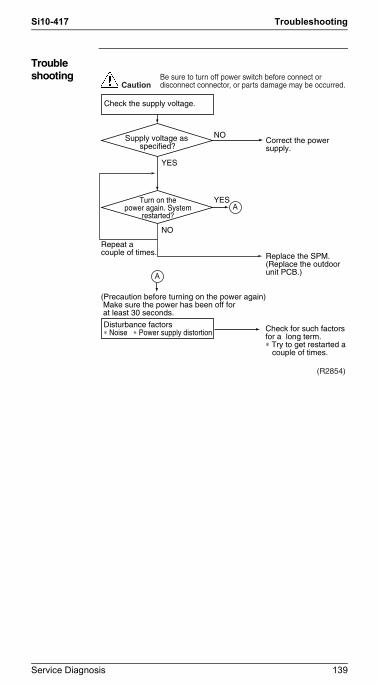
Si10-417 Troubleshooting
Si10-417.fm Page 139 Wednesday, September 22, 2004 6:38 PM
Troubleshooting
Check the supply voltage.
Correct the power supply.
Replace the SPM.(Replace the outdoor unit PCB.)
(R2854)
Supply voltage as specified?
NO
YES
Turn on thepower again. System
restarted?
NO
Repeat a couple of times.
YES
Disturbance factors∗ Noise ∗ Power supply distortion
A
A
CautionBe sure to turn off power switch before connect or disconnect connector, or parts damage may be occurred.
(Precaution before turning on the power again) Make sure the power has been off for at least 30 seconds.
Check for such factorsfor a long term.∗ Try to get restarted a couple of times.
Service Diagnosis 139

Troubleshooting Si10-417
Si10-417.fm Page 140 Wednesday, September 22, 2004 6:38 PM
5.3.8 Over-voltage Detection
Remote Controller Display
U2
Method of Malfunction Detection
An abnormal voltage rise is detected by checking the detection circuit or DC voltage detection circuit.
Malfunction Decision Conditions
An over-voltage signal is fed from the over-voltage detection circuit to the microcomputer, or more than 430 V occurred the voltage detected by the DC voltage detection circuit.The system will be shut down if the error occurs 4 times.Clearing condition: Continuous run for about 60 minutes (normal)
Supposed Causes
Supply voltage not as specifiedOver-voltage detector or DC voltage detection circuit defectivePAM control part(s) defective
140 Service Diagnosis

Si10-417 Troubleshooting
Si10-417.fm Page 141 Wednesday, September 22, 2004 6:38 PM
Troubleshooting
Note: If the model doesn't have SPM, replace the outdoor unit PCB.
Check the supply voltage.
Correct the power supply.
Replace the SPM.(Replace the outdoor unit PCB.)
Check for such factors for a long term.∗ Try to get restarted a couple of times.
(R2854)
Supply voltage as specified?
NO
YES
Turn on thepower again.
System restarted?
NO
Repeat a couple of times.
YES
(Precaution before turning on the power again) Make sure the power has been off for at least 30 seconds.Disturbance factors∗ Noise ∗ Power supply distortion
A
A
CautionBe sure to turn off power switch before connect or disconnect connector, or parts damage may be occurred.
Service Diagnosis 141

Troubleshooting Si10-417
Si10-417.fm Page 142 Wednesday, September 22, 2004 6:38 PM
5.3.9 Signal Transmission Error (between Indoor and Outdoor Units)
Remote Controller Display
U4
Method of Malfunction Detection
The data received from the outdoor unit in indoor unit-outdoor unit signal transmission is checked whether it is normal.
Malfunction Decision Conditions
When the data sent from the outdoor unit cannot be received normally, or when the content of the data is abnormal.
Supposed Causes
Faulty outdoor unit PCB.Faulty indoor unit PCB.Indoor unit-outdoor unit signal transmission error due to wiring error.Indoor unit-outdoor unit signal transmission error due to disturbed power supply waveform.Indoor unit-outdoor unit signal transmission error due to breaking of wire in the connection wires between the indoor and outdoor units (wire No. 2).
142 Service Diagnosis

Si10-417 Troubleshooting
Si10-417.fm Page 143 Wednesday, September 22, 2004 6:38 PM
Troubleshooting
Check No.10Refer to
P.162 Check the outdoor unit's LED A.
Check the indoor unit-outdoor unit connection wires.
YES
YES
Correct the indoor unit-outdoor unit connection wires.
Diagnose the outdoor unit.
Replace the connection wires between the indoor and outdoor units.
Replace indoor unit control PCB .
Locate the cause of the disturbance of the power supply waveform, and correct it.
Is there any wiring error?
NO
(R2840)
Is LED A flashing?
Is the voltage 0 V?
NO
Check No. 10Check power supply waveform.
Check the voltage of the indoor unit-outdoor unit connection wires between No. 1 and No. 2, and between No 2 and No. 3.
YES
YES
NO
Is there any disturbance?
NO
CautionBe sure to turn off power switch before connect or disconnect connector, or parts damage may be occurred.
Service Diagnosis 143

Troubleshooting Si10-417
Si10-417.fm Page 144 Wednesday, September 22, 2004 6:38 PM
5.3.10 Outdoor Unit PCB Abnormality or Signal Transmission Circuit Abnormality
Remote Controller Display
U4
Method of Malfunction Detection
The data received from the outdoor unit in indoor unit-outdoor unit signal transmission is checked whether it is normal.
Malfunction Decision Conditions
When the data sent from the outdoor unit cannot be received normally, or when the content of the data is abnormal.If the indoor unit cannot communicate with the outdoor unit for 15 seconds, the system will be shut down.
Supposed Causes
Faulty outdoor unit PCB.Faulty indoor unit PCB.Indoor unit-outdoor unit signal transmission error due to wiring error.Indoor unit-outdoor unit signal transmission error due to breaking of wire in the connection wires between the indoor and outdoor units (the transmission wire).
144 Service Diagnosis

Si10-417 Troubleshooting
Si10-417.fm Page 145 Wednesday, September 22, 2004 6:38 PM
Troubleshooting
Check the indoor unit-outdoor unit connection wires.
YES Correct the indoor unit-outdoor unit connection wires.
Replace the connection wirings.
Carry out the wiring work within the regulation. (less than 30m)
Replace the outdoor unit PCB.
Replace the indoor unit PCB.
Replace the outdoor unit PCB.
Is there any wiring error?
(R3046)
Not enough
YESThe connection wiring length over
30m?
NO
Fully insulated?ex. between wirings,
earth.Fine
NOCheck the outdoor unit's LED A.
NOIs LED A flashing?
YES
Disconnect the No.3 terminal.
Check the voltage of the indoor unit-outdoor unit connection wires between No.2 and No. 3. (Touch the No.2 termintal with (-) in DC range)
Is the voltage 30~50V?YES
NO
CautionBe sure to turn off power switch before connect or disconnect connector, or parts damage may be occurred.
Service Diagnosis 145

Troubleshooting Si10-417
Si10-417.fm Page 146 Wednesday, September 22, 2004 6:38 PM
5.3.11 Unspecified Voltage (between Indoor and Outdoor Units)
Remote Controller Display
UA
Method of Malfunction Detection
The supply power is detected for its requirements (different from separate type and multi type) by the indoor / outdoor transmission signal.
Malfunction Decision Conditions
The separate type and multi type are interconnected.
Supposed Causes
Wrong models interconnectedWrong indoor unit PCB mountedIndoor unit PCB defectiveWrong outdoor unit PCB mounted or defective
Troubleshooting
Check the indoor and outdoor unit model numbers.
Match the compatible models.
Change for the specified PC board (1) or (2).
Replace the indoor unit PC board (1) (or the outdoor unit PC board).
(Q0347)
Indoor unitand outdoor unit
matched?
NO
YES
YES
Matched compatibly?NO
Check the code numbers (2P01234, for example) of the indoor and outdoor unit PC boards with the Parts List.
CautionBe sure to turn off power switch before connect or disconnect connector, or parts damage may be occurred.
146 Service Diagnosis

Si10-417 Troubleshooting
Si10-417.fm Page 147 Wednesday, September 22, 2004 6:38 PM
5.3.12 Anti-icing Function in Other Rooms / Unspecified Voltage (between Indoor and Outdoor Units)
Remote Controller Display
UA, UH
Outdoor Unit LED Display
A 5 1 1 2 1 3 1 4 1
Method of Malfunction Detection
A wrong connection is detected by checking the combination of indoor and outdoor units on the microcomputer.
Malfunction Decision Conditions
Operation halt due to the anti-icing function in other roomsOperation halt due to unspecified internal and/or external voltagesOperation halt due to mismatching of indoor and outdoor units
Supposed Causes
Operation halt due to the anti-icing function in other roomsWrong connections at the indoor unitPCB wrongly connected
Troubleshooting
(R3066)
Error-displayingair-conditioner
running?
NO
YES
Supply voltageas specified?
NO
Check the model name.
YES
Normal?NO
YES
Check the combination of all the models being connected.
The freeze protection function is activated in other rooms. Refer to A5.
Correct.
Reconnect.
CautionBe sure to turn off power switch before connect or disconnect connector, or parts damage may be occurred.
Service Diagnosis 147

Troubleshooting Si10-417
Si10-417.fm Page 148 Wednesday, September 22, 2004 6:38 PM
5.3.13 Anti-icing Function in Other Rooms / Unspecified Voltage (between Indoor and Outdoor Units)
Remote Controller Display
UA,UH
Method of Malfunction Detection
A wrong connection is detected by checking the combination of indoor and outdoor units on the microcomputer.
Malfunction Decision Conditions
Operation halt due to the anti-icing function in other roomsOperation halt due to unspecified voltage between indoor and outdoor units
Supposed Causes
Operation halt due to the anti-icing function in other roomsWrong connections at the indoor unitPCB wrongly connected
Troubleshooting
The anti-icing function is activated in other rooms. Refer to A5.
Correct.
Reconnect.
(R3045)
Error-displayingair-conditioner
running?
NO
YES
Supply voltage as specified?
NO
YES
Check the model number.
Normal?NO
YESCheck the combination of all the models being connected.
CautionBe sure to turn off power switch before connect or disconnect connector, or parts damage may be occurred.
148 Service Diagnosis

Si10-417 Troubleshooting
Si10-417.fm Page 149 Wednesday, September 22, 2004 6:38 PM
5.4 Check5.4.1 Fan Motor Connector Output Check
Check No.01
1. Check connector connection.2. Check motor power supply voltage output
(pins 4-7 and 4-8).3. Check motor control voltage (pins 4-3).4. Check rotation command voltage output (pins 4-2).5. Check rotation pulse input (pins 4-1).
7654321
Motor power supply voltageUnusedUnusedP.0V (reference potential)Motor control voltage (15 VDC)Rotation command voltage (1~ 6 VDC)Rotation pulse input
S1
(R3199)
7654321
Motor power supply voltageUnusedUnusedP.0V (reference potential)Motor control voltage (15 VDC)Rotation command voltage (1~ 5 VDC)Rotation pulse input
<In case of Floor Standing Type>Upper fan connector
87654321
Motor power supply voltageUnusedUnusedUnusedP.0V (reference potential)Motor control voltage (15 VDC)Rotation command voltage (1 to 5 VDC)Rotation pulse input
Lower fan connector
(R1224)
Service Diagnosis 149

Troubleshooting Si10-417
Si10-417.fm Page 150 Wednesday, September 22, 2004 6:38 PM
Check No.02
1. Check connector connection.2. Check motor control voltage output (pins 2-1).
5.4.2 Limit Switch Continuity Check
Check No.3
Remove the front grille. The limit switch is located at the left side of the drain pan assembly. Check the continuity of the switch connection.
∗ The shutter can be opened and closed with hand. Keep the shutter open and closed all the way for each continuity check steps.
54321
Motor power supply voltageUnusedUnusedP.0V (reference potential)Motor control power supply
S202
(R1073)
Tester
Limit switch
Forward
Upward
Shutter status
Continuity
Closed
No continuity
Open
Continuity
(Q0363)
150 Service Diagnosis
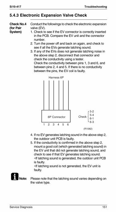
Si10-417 Troubleshooting
Si10-417.fm Page 151 Wednesday, September 22, 2004 6:38 PM
5.4.3 Electronic Expansion Valve Check
Check No.4(for Pair System)
Conduct the followings to check the electronic expansion valve (EV).1. Check to see if the EV connector is correctly inserted
in the PCB. Compare the EV unit and the connector number.
2. Turn the power off and back on again, and check to see if all the EVs generate latching sound.
3. If any of the EVs does not generate latching noise in the above step 2, disconnect that connector and check the conductivity using a tester.Check the conductivity between pins 1, 3 and 6, and between pins 2, 4 and 5. If there is no conductivity between the pins, the EV coil is faulty.
4. If no EV generates latching sound in the above step 2, the outdoor unit PCB is faulty.
5. If the conductivity is confirmed in the above step 2, mount a good coil (which generated latching sound) in the EV unit that did not generate latching sound, and check to see if that EV generates latching sound.∗If latching sound is generated, the outdoor unit PCB is faulty.∗If latching sound is not generated, the EV unit is faulty.
Note: Please note that the latching sound varies depending on the valve type.
Harness 6P
6P Connector Check
5-25-46-16-3
1 2 3 4 5 6(R1082)
Service Diagnosis 151
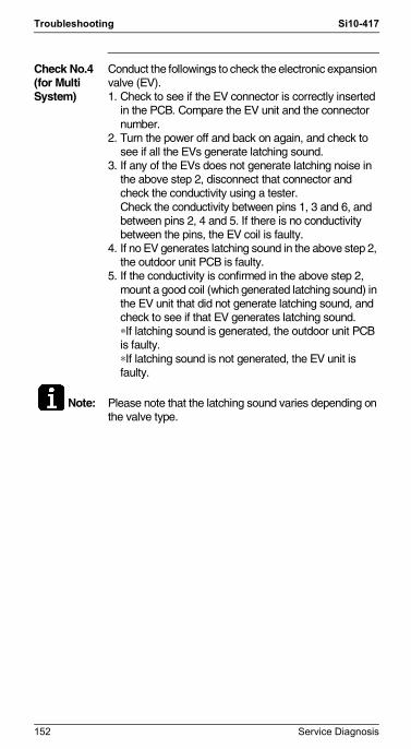
Troubleshooting Si10-417
Si10-417.fm Page 152 Wednesday, September 22, 2004 6:38 PM
Check No.4(for Multi System)
Conduct the followings to check the electronic expansion valve (EV).1. Check to see if the EV connector is correctly inserted
in the PCB. Compare the EV unit and the connector number.
2. Turn the power off and back on again, and check to see if all the EVs generate latching sound.
3. If any of the EVs does not generate latching noise in the above step 2, disconnect that connector and check the conductivity using a tester.Check the conductivity between pins 1, 3 and 6, and between pins 2, 4 and 5. If there is no conductivity between the pins, the EV coil is faulty.
4. If no EV generates latching sound in the above step 2, the outdoor unit PCB is faulty.
5. If the conductivity is confirmed in the above step 2, mount a good coil (which generated latching sound) in the EV unit that did not generate latching sound, and check to see if that EV generates latching sound.∗If latching sound is generated, the outdoor unit PCB is faulty.∗If latching sound is not generated, the EV unit is faulty.
Note: Please note that the latching sound varies depending on the valve type.
152 Service Diagnosis

Si10-417 Troubleshooting
Si10-417.fm Page 153 Wednesday, September 22, 2004 6:38 PM
Valve Body Condition (Symptom) Check Method / Measure
(1) Valve body catches at fully opened or half opened position.(Symptom)Cooling:
Water leakage at the no-operation unit
Flow noise of refrigerant in the no-operation unit
Operation halt due to icing protection
Heating:The unit does not
heatRefrigerant flow rate
vary by unit (Discharge air temperatures are different by room)
Peak cut
Reset power supply and conduct cooling operation unit by unit.
(2) Valve body catches at complete close position.(Symptom)Cooling:
The only unit having problem does not cool the room .
When the only faulty unit is in operation, the unit makes pump down.(The low pressure of the unit becomes vacuum)
IT is activated.Abnormal discharge
pipe temperature
Heating:Insufficient gas due to liquid refrigerant stagnation inside the faulty indoor unit
(Only for heat pump model)
The unit does not heat the room.
IT is activated.Abnormal discharge
pipe temperature
Reset power supply and conduct cooling operation unit by unit.
Check the liquid pipe temperature of no-operation unit.
YES
Is it almostsame as the outside
air temperature?
(R1431)
NO
Replace the EVn of the room.
Check the low pressure
Does thepressure become into
vacuum zone?
(R1432)
YES
NO
Replace the EVn of the room.
Service Diagnosis 153

Troubleshooting Si10-417
Si10-417.fm Page 154 Wednesday, September 22, 2004 6:38 PM
(3) Valve does not open fully.(Symptom)
The unit does not cool nor heat (only for heat pump model.)
IT is actuated.Abnormal discharge
pipe temperature
Check the number of rotation of shaft if it is 5 and half from full open to complete close using manual coil for electronic expansion valve. When the number of rotation of shaft is less than the above value, the valve may catch anywhere of the body.
Valve Body Condition (Symptom) Check Method / Measure
154 Service Diagnosis

Si10-417 Troubleshooting
Si10-417.fm Page 155 Wednesday, September 22, 2004 6:38 PM
5.4.4 Four Way Valve Performance Check
Check No.5-1 Turn off the power and turn it
on again.
Start the heating-mode run.
Replace the outdoor unit PCB.
Replace the four way valve coil.
Replace the four way valve.
(R2856)
NO
∗ Four way valve coil Cooling / dry : No continuity Heating : Continuity
YES
YES
Four way valvecoil resistance at 1500
Ω?
NO
S80 voltageat DC 180-220 V with
compressor on? (Fig. 1)
Disconnect the four way valve coil from the connector and check the continuity.
(Fig. 1)Voltage at S80
DC180-220V
ONCompressor
Time
Service Diagnosis 155

Troubleshooting Si10-417
Si10-417.fm Page 156 Wednesday, September 22, 2004 6:38 PM
Check No.5-2 Turn off the power and turn it
on again.
Start the heating-mode run.
Replace the outdoor unit PCB.
Replace the four way valve coil.
Replace the four way valve.
∗ Four way valve coil Cooling / dry : No continuity Heating : Continuity
YES
YES
NO
S80 voltageat DC 180-220 V with
compressor on? (Fig. 1)
Disconnect the four way valve coil from the connector and check the continuity.
Four way valvecoil resistance at
3kΩ±0.5kΩ?
(R3047)
(Fig. 1)Voltage at S80
DC180-220V
ONCompressor
Time
NO
156 Service Diagnosis

Si10-417 Troubleshooting
Si10-417.fm Page 157 Wednesday, September 22, 2004 6:38 PM
5.4.5 Thermistor Resistance Check
Check No.6 Remove the connectors of the thermistors on the PCB, and measure the resistance of each thermistor using tester.The relationship between normal temperature and resistance is shown in the graph and the table below.
Thermistor R25°C=20kΩ B=3950
Temperature (°C)
-20 211.0 (kΩ)
-15 150
-10 116.5
-5 88
0 67.2
5 51.9
10 40
15 31.8
20 25
25 20
30 16
35 13
40 10.6
45 8.7
50 7.2
Service Diagnosis 157

Troubleshooting Si10-417
Si10-417.fm Page 158 Wednesday, September 22, 2004 6:38 PM
5.4.6 Installation Condition Check
Check No.7-1
Installation condition check
Normal
Change the position of the air discharge grille or the installation location.
Change the position of the air discharge grille or the installation location.
Clean the heat exchanger.
Change the installation location or direction.
Check the outside air temperature (temperature of air taken in by the outdoor unit). (The outside air temperature shall be 43˚C or lower.)
Check the allowable
dimensions of the air suctionand discharge
area.
Is theair flow blocked by
obstacles or winds blowingin the opposite
direction?
(R1438)
Abnormal
YES
YES
YES
Doesthe discharged
air from other outdoorunit cause an increase of
the suction airtemperature?
NO
NO
NO
Is the heat exchangervery dirty?
158 Service Diagnosis

Si10-417 Troubleshooting
Si10-417.fm Page 159 Wednesday, September 22, 2004 6:38 PM
Check No.7-2
Installation condition check
Change the position of the air discharge grille or the installation location.
Change the position of the air discharge grille or the installation location.
Clean the heat exchanger.
Change the installation location or direction.
Check the outside air temperature (temperature of air taken in by the outdoor unit). (The outside air temperature shall be 46˚C or lower.)
Check the allowable
dimensions of the air suctionand discharge
area.
Is theair flow blocked by
obstacles or winds blowingin the opposite
direction?
Doesthe discharged
air from other outdoorunit cause an increase of
the suction airtemperature?
Isthe heat exchanger
very dirty?
Abnormal
YES
YES
YES
Normal
NO
NO
NO
(R3048)
Service Diagnosis 159

Troubleshooting Si10-417
Si10-417.fm Page 160 Wednesday, September 22, 2004 6:38 PM
5.4.7 Discharge Pressure Check
Check No.8
5.4.8 Outdoor Unit Fan System Check
Check No.9 With DC Motor
Discharge pressure check
Replace compessor.
Open the stop valve.
Replace the pipe installed at the site.
Clean.
Replace the compressor.
(R1443)
YES
YES
YES
NO
NO
NO
NO
At the heat exchanger and
air filter dirty?
Is the stop valve open?
Is the connectionpipe deformed?
YES
High
Check the outdoor unit fan system.
Reconnect.
(R2857)
Outdoor unit fan running?
YES
Fan motorlead wire connector
disconnected?
YES
NO
NO
Outdoor unit fan system functioning.
Go to Check No. 15-1·2.
A
A
160 Service Diagnosis

Si10-417 Troubleshooting
Si10-417.fm Page 161 Wednesday, September 22, 2004 6:38 PM
With AC Motor
Check thefan motor lead wire connector for secure
connection.
Abnormal
YES
NO
NO
Continuity
Are the resistance at connector leads ∞? 1. red - black,
2. white -black
Check the fancapacitor for continuity.
Does the outdoor fan rotate?
Does the outdoor unit fan
start just after the poweris turned on?
Check the outdoor fan system.
YES
YES
NO
Normal
No continuity
Repair.
Replace the fan motor.
Replace the fan motor.
Replace the outdoor unit PCB.
The outdoor fan system is normal.
(R2670)
Service Diagnosis 161
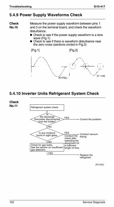
Troubleshooting Si10-417
Si10-417.fm Page 162 Wednesday, September 22, 2004 6:38 PM
5.4.9 Power Supply Waveforms Check
Check No.10
Measure the power supply waveform between pins 1 and 3 on the terminal board, and check the waveform disturbance.
Check to see if the power supply waveform is a sine wave (Fig.1).Check to see if there is waveform disturbance near the zero cross (sections circled in Fig.2)
5.4.10 Inverter Units Refrigerant System Check
Check No.11
[Fig.1] [Fig.2]
Refrigerant system check
Check for gas leaks.See the section on insufficient gas detection.
Conduct the check after operating theequipment for a sufficient length of time.
Correct the problem.
Conduct vacuum drying.
Replace the refrigerant.
Isthe discharge
thermister disconnectedfrom the holder?
(R1445)
YES
YES
YES
Is any moisturefound in sight glass.
NO
NO
162 Service Diagnosis

Si10-417 Troubleshooting
Si10-417.fm Page 163 Wednesday, September 22, 2004 6:38 PM
5.4.11 Capacitor Voltage Check
Check No.12
Checking the capacitor voltageWith the circuit breaker still on, measure the voltage at the power transistor (+) and (-) terminals. Set the multi-tester to DC and VOLTAGE RANGE before measurement. Be careful never to touch any live parts.
* Since capacitor (+) and (-) are connected to power transistor (+) and (-), capacitor voltage can be measured at the power transistor (+) and (-) terminals.
5.4.12 Power Transistor Check
Check No.13
Checking the power transistorNever touch any live parts for at least 10 minutes after turning off the circuit breaker.If you cannot avoid to touch a live part, make sure that the power transistor's supply voltage is below 50 V using the tester.For the UVW, make measurements at the Faston terminal on the board or the relay connector.
Tester's negative terminal
Power transistor
(+)UVW
Power transistor
(–)UVW
Tester's positive terminal
UVWPower
transistor (+)
UVWPower
transistor(–)
Normal resistance Several kΩ to several MΩ
Abnormal resistance 0 or ∞
Service Diagnosis 163

Troubleshooting Si10-417
Si10-417.fm Page 164 Wednesday, September 22, 2004 6:38 PM
5.4.13 Main Circuit Electrolytic Capacitor Check
Check No.14
Checking the main circuit electrolytic capacitorNever touch any live parts for at least 10 minutes after turning off the circuit breaker.If unavoidably necessary to touch a live part, make sure there is no DC voltage using the tester.Check the continuity with the tester. Reverse the pins and make sure there is continuity.
164 Service Diagnosis
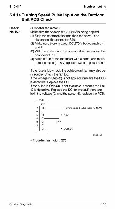
Si10-417 Troubleshooting
Si10-417.fm Page 165 Wednesday, September 22, 2004 6:38 PM
5.4.14 Turning Speed Pulse Input on the Outdoor Unit PCB Check
Check No.15-1
<Propeller fan motor>Make sure the voltage of 270±30V is being applied.(1) Stop the operation first and then the power, and
disconnect the connector S70.(2) Make sure there is about DC 270 V between pins 4
and 7.(3) With the system and the power still off, reconnect the
connector S70.(4) Make a turn of the fan motor with a hand, and make
sure the pulse (0-15 V) appears twice at pins 1 and 4.
If the fuse is blown out, the outdoor-unit fan may also be in trouble. Check the fan too.If the voltage in Step (2) is not applied, it means the PCB is defective. Replace the PCB.If the pulse in Step (4) is not available, it means the Hall IC is defective. Replace the DC fan motor.If there are both the voltage (2) and the pulse (4), replace the PCB.
∗ Propeller fan motor : S70
7654321 DC270V
S70
PCB
Turning speed pulse input (0-15 V)
15V
(R2859)
Service Diagnosis 165

Troubleshooting Si10-417
Si10-417.fm Page 166 Wednesday, September 22, 2004 6:38 PM
Check No.15-2
<Propeller fan motor>Make sure the voltage of 290~380V is being applied.(1) Stop the operation first and then the power off, and
disconnect the connector S70.(2) Make sure there is about DC 280 V between pins 4
and 7.(3) With the system and the power still off, reconnect the
connector S70.(4) Make a turn of the fan motor with a hand, and make
sure the pulse (0-15 V) appears twice at pins 1 and 4.
If the fuse is blown out, the outdoor-unit fan may also be in trouble. Check the fan too.If the voltage in Step (2) is not applied, it means the PCB is defective. Replace the PCB.If the pulse in Step (4) is not available, it means the Hall IC is defective. Replace the DC fan motor.If there are both the voltage (2) and the pulse (4), replace the PCB.
∗ Propeller fan motor : S70
7654321
Turning speed control voltage (DC~6.5V)Turning speed pulse input
Fan motor power supply voltage (310~340V)
P.0V (reference of electric potential)Fan motor control voltage (DC15V)
(R3052)
PCB
S70
166 Service Diagnosis

Si10-417 Troubleshooting
Si10-417.fm Page 167 Wednesday, September 22, 2004 6:38 PM
5.4.15 Hall IC Check
Check No.16
1. Check the connector connection.2. With the power ON, operation OFF, and the connector
connected, check the following.∗Output voltage of about 5 V between pins 1 and 3.∗Generation of 3 pulses between pins 2 and 3 when the fan motor is operating.
Failure of (1) faulty PCB Replace the PCB.Failure of (2) faulty hall IC Replace the fan motor.Both (1) and (2) result Replace the PCB.
Service Diagnosis 167

The specifications, designs, and information in this brochure are subject to change without notice.
All rights reservedc
DealerHead Office:Umeda Center Bldg., 4-12, Nakazaki-Nishi2-chome, Kita-ku, Osaka, 530-8323 Japan
Tokyo Office:JR Shinagawa East Bldg., 18-1, Konan2-chome, Minato-ku, Tokyo, 108-0075 Japan
http://www.daikin.com/global/
Printed in Japan 09/2004 AK
Cover.fm Page 2 Wednesday, September 22, 2004 6:36 PM