Styx Mill Reserve Equipment Shed
39
Styx Mill Reserve Equipment Shed PRK 0340-BLDG-004 EQ2 Detailed Engineering Evaluation Qualitative Report Version FINAL 130 Hussey Road, Harewood
Transcript of Styx Mill Reserve Equipment Shed

Styx Mill Reserve Equipment Shed PRK 0340-BLDG-004 EQ2
Detailed Engineering Evaluation Qualitative Report
Version FINAL
130 Hussey Road, Harewood

Styx Mill Reserve Equipment Shed PRK 0340-BLDG-004 EQ2
Detailed Engineering Evaluation Qualitative Report
Version FINAL
130 Hussey Road, Harewood
Christchurch City Council
Prepared By Razel Ramilo
Reviewed By Stephen Lee
Date
31/10/12

51/30596/67/
Detailed Engineering Evaluations Styx Mill Reserve Equipment Shed
Contents
Qualitative Report Summary i
1. Background 1
2. Compliance 2
2.1 Canterbury Earthquake Recovery Authority (CERA) 2
2.2 Building Act 3
2.3 Christchurch City Council Policy 4
2.4 Building Code 4
3. Earthquake Resistance Standards 5
4. Building Description 7
4.1 General 7
4.2 Gravity Load Resisting System 8
4.3 Lateral Load Resisting System 8
5. Assessment 9
6. Damage Assessment 10
6.1 Surrounding Buildings 10
6.2 Residual Displacements and General Observations 10
6.3 Ground Damage 10
7. Critical Structural Weakness 11
7.1 Short Columns 11
7.2 Lift Shaft 11
7.3 Roof 11
7.4 Plan Irregularity 11
7.5 Vertical Irregularity 11
7.6 Staircases 11
8. Geotechnical Consideration 12
8.1 Site Description 12
8.2 Published Information on Ground Conditions 12
8.3 Seismicity 13
8.4 Recommendations 15

51/30596/67/
Detailed Engineering Evaluations Styx Mill Reserve Equipment Shed
8.5 Conclusions & Summary 15
9. Survey 16
10. Initial Capacity Assessment 17
10.1 % NBS Assessment 17
10.2 Seismic Parameters 17
10.3 Expected Structural Ductility Factor 17
10.4 Discussion of Results 17
10.5 Occupancy 17
11. Initial Conclusions 18
12. Recommendations 19
13. Limitations 20
13.1 General 20
13.2 Geotechnical Limitations 20
Table Index
Table 3.1 %NBS compared to relative risk of failure 6
Table 3 ECan Borehole Summary 12
Table 4 Summary of Known Active Faults , 14
Appendices
A Photographs
B Existing Drawings
C CERA Building Evaluation Form

51/30596/67/
Detailed Engineering Evaluations Styx Mill Reserve Equipment Shed
Qualitative Report Summary
Styx Mill Reserve Equipment Shed
PRK 0340-BLDG-004 EQ2
Detailed Engineering Evaluation
Qualitative Report - SUMMARY
Version FINAL
130 Hussey Road, Harewood
Background
This is a summary of the Qualitative report for the building structure, and is based in general on the
Detailed Engineering Evaluation Procedure document (draft) issued by the Structural Advisory Group on
19 July 2011 and visual inspections on 17 April 2012.
Building Description
The Equipment Shed is located at 130 Hussey Road within Styx Mill Reserve in Harewood,
Christchurch. The building is situated close to a few residential buildings to the north and east.
The building is approximately 10m long, 9.7m wide and 4m in height. The overall footprint of the building
is approximately 97m2. The building was constructed on 1999. No alterations have been made to the
building since construction.
The structure is made of steel UB portal frames with timber roof purlins clad with corrugated metal
roofing. Two diagonal steel angle roof bracings are located in the northeast and southwest roof
quadrants. The walls have steel posts with timber purlins and are clad with corrugated metal sheeting.
A timber framed office has been constructed within the Equipment Shed. The timber walls of the office
are not load bearing.
The building’s foundation consists of concrete strip footings to the external perimeter connected to the
concrete floor slab founded on hardfill.
Key Damage Observed
No apparent damage was observed.
Critical Structural Weaknesses
No potential critical structural weakness has been identified.

51/30596/67/
Detailed Engineering Evaluations Styx Mill Reserve Equipment Shed
Indicative Building Strength (from IEP and CSW assessment)
Based on the information available, and using the NZSEE Initial Evaluation Procedure, the building’s
original capacity has been assessed to be in the order of 85% NBS and post-earthquake capacity in the
order of 85% NBS.
The building has been assessed to have a seismic capacity in the order of 85% NBS and is therefore
not a potential Earthquake Risk.
Recommendations
It is recommended that:
a) As the building does not have any apparent damage and has achieved greater than 67% NBS
following an initial IEP assessment, the building can remain occupied as per Christchurch City
Council’s policy.
b) No detailed quantitative assessment is required.

51/30596/67/
Detailed Engineering Evaluations Styx Mill Reserve Equipment Shed
1. Background
GHD Limited has been engaged by the Christchurch City Council (CCC) to undertake a detailed
engineering evaluation of the Equipment Shed located at Styx Mill Reserve.
This report is a Qualitative Assessment of the building structure, and is based generally on the Detailed
Engineering Evaluation Procedure document (draft) issued by the Structural Advisory Group on 19 July
2011.
A qualitative assessment involves inspections of the building and a desktop review of existing structural
and geotechnical information, including existing drawings and calculations, if available.
The purpose of the assessment is to determine the likely building performance and damage patterns, to
identify any potential critical structural weaknesses or collapse hazards, and to make an initial
assessment of the likely building strength in terms of percentage of new building standard (%NBS).
At the time of this report, no intrusive site investigation, detailed analysis, or modelling of the building
structure had been carried out. A planning drawing was made available. The building description below
is based on our visual inspections and the planning drawing available.

51/30596/67/
Detailed Engineering Evaluations Styx Mill Reserve Equipment Shed
2. Compliance
This section contains a brief summary of the requirements of the various statutes and authorities that
control activities in relation to buildings in Christchurch at present.
2.1 Canterbury Earthquake Recovery Authority (CERA)
CERA was established on 28 March 2011 to take control of the recovery of Christchurch using powers
established by the Canterbury Earthquake Recovery Act enacted on 18 April 2011. This act gives the
Chief Executive Officer of CERA wide powers in relation to building safety, demolition and repair. Two
relevant sections are:
Section 38 – Works
This section outlines a process in which the chief executive can give notice that a building is to be
demolished and if the owner does not carry out the demolition, the chief executive can commission the
demolition and recover the costs from the owner or by placing a charge on the owners’ land.
Section 51 – Requiring Structural Survey
This section enables the chief executive to require a building owner, insurer or mortgagee carry out a full
structural survey before the building is re-occupied.
We understand that CERA will require a detailed engineering evaluation to be carried out for all
buildings (other than those exempt from the Earthquake Prone Building definition in the Building Act). It
is anticipated that CERA will adopt the Detailed Engineering Evaluation Procedure document (draft)
issued by the Structural Advisory Group on 19 July 2011. This document sets out a methodology for
both qualitative and quantitative assessments.
The qualitative assessment is a desk-top and site inspection assessment. It is based on a thorough
visual inspection of the building coupled with a review of available documentation such as drawings and
specifications. The quantitative assessment involves analytical calculation of the buildings strength and
may require non-destructive or destructive material testing, geotechnical testing and intrusive
investigation.
It is anticipated that factors determining the extent of evaluation and strengthening level required will
include:
The importance level and occupancy of the building
The placard status and amount of damage
The age and structural type of the building
Consideration of any critical structural weaknesses
The extent of any earthquake damage

51/30596/67/
Detailed Engineering Evaluations Styx Mill Reserve Equipment Shed
2.2 Building Act
Several sections of the Building Act are relevant when considering structural requirements:
Section 112 – Alterations
This section requires that an existing building complies with the relevant sections of the Building Code to
at least the extent that it did prior to any alteration. This effectively means that a building cannot be
weakened as a result of an alteration (including partial demolition).
Section 115 – Change of Use
This section requires that the territorial authority (in this case Christchurch City Council (CCC)) be
satisfied that the building with a new use complies with the relevant sections of the Building Code ‘as
near as is reasonably practicable’. Regarding seismic capacity ‘as near as reasonably practicable’ has
previously been interpreted by CCC as achieving a minimum of 67% NBS however where practical
achieving 100% NBS is desirable. The New Zealand Society for Earthquake Engineering (NZSEE)
recommend a minimum of 67% NBS.
2.2.1 Section 121 – Dangerous Buildings
The definition of dangerous building in the Act was extended by the Canterbury Earthquake (Building
Act) Order 2010, and it now defines a building as dangerous if:
In the ordinary course of events (excluding the occurrence of an earthquake), the building is likely
to cause injury or death or damage to other property; or
In the event of fire, injury or death to any persons in the building or on other property is likely
because of fire hazard or the occupancy of the building; or
There is a risk that the building could collapse or otherwise cause injury or death as a result of
earthquake shaking that is less than a ‘moderate earthquake’ (refer to Section 122 below); or
There is a risk that that other property could collapse or otherwise cause injury or death; or
A territorial authority has not been able to undertake an inspection to determine whether the
building is dangerous.
Section 122 – Earthquake Prone Buildings
This section defines a building as earthquake prone if its ultimate capacity would be exceeded in a
‘moderate earthquake’ and it would be likely to collapse causing injury or death, or damage to other
property. A moderate earthquake is defined by the building regulations as one that would generate
ground shaking 33% of the shaking used to design an equivalent new building.
Section 124 – Powers of Territorial Authorities
This section gives the territorial authority the power to require strengthening work within specified
timeframes or to close and prevent occupancy to any building defined as dangerous or earthquake
prone.
Section 131 – Earthquake Prone Building Policy
This section requires the territorial authority to adopt a specific policy for earthquake prone, dangerous
and insanitary buildings.

51/30596/67/
Detailed Engineering Evaluations Styx Mill Reserve Equipment Shed
2.3 Christchurch City Council Policy
Christchurch City Council adopted their Earthquake Prone, Dangerous and Insanitary Building Policy in
2006. This policy was amended immediately following the Darfield Earthquake of the 4th September
2010.
The 2010 amendment includes the following:
A process for identifying, categorising and prioritising Earthquake Prone Buildings, commencing on
1 July 2012;
A strengthening target level of 67% of a new building for buildings that are Earthquake Prone;
A timeframe of 15-30 years for Earthquake Prone Buildings to be strengthened; and,
Repair works for buildings damaged by earthquakes will be required to comply with the above.
The council has stated their willingness to consider retrofit proposals on a case by case basis,
considering the economic impact of such a retrofit.
We anticipate that any building with a capacity of less than 33% NBS (including consideration of critical
structural weaknesses) will need to be strengthened to a target of 67% NBS of new building standard as
recommended by the Policy.
If strengthening works are undertaken, a building consent will be required. A requirement of the consent
will require upgrade of the building to comply ‘as near as is reasonably practicable’ with:
The accessibility requirements of the Building Code.
The fire requirements of the Building Code. This is likely to require a fire report to be submitted with
the building consent application.
2.4 Building Code
The building code outlines performance standards for buildings and the Building Act requires that all
new buildings comply with this code. Compliance Documents published by The Department of Building
and Housing can be used to demonstrate compliance with the Building Code.
After the February Earthquake, on 19 May 2011, Compliance Document B1: Structure was amended to
include increased seismic design requirements for Canterbury as follows:
Hazard Factor increased from 0.22 to 0.3 (36% increase in the basic seismic design load)
Serviceability Return Period Factor increased from 0.25 to 0.33 (80% increase in the serviceability
design loads when combined with the Hazard Factor increase)
The increase in the above factors has resulted in a reduction in the level of compliance of an existing
building relative to a new building despite the capacity of the existing building not changing.

51/30596/67/
Detailed Engineering Evaluations Styx Mill Reserve Equipment Shed
3. Earthquake Resistance Standards
For this assessment, the building’s earthquake resistance is compared with the current New Zealand
Building Code requirements for a new building constructed on the site. This is expressed as a
percentage of new building standard (%NBS). The new building standard load requirements have been
determined in accordance with the current earthquake loading standard (NZS 1170.5:2004 Structural
design actions - Earthquake actions - New Zealand).
The likely capacity of this building has been derived in accordance with the New Zealand Society for
Earthquake Engineering (NZSEE) guidelines ‘Assessment and Improvement of the Structural
Performance of Buildings in Earthquakes’ (AISPBE), 2006. These guidelines provide an Initial
Evaluation Procedure that assesses a buildings capacity based on a comparison of loading codes from
when the building was designed and currently. It is a quick high-level procedure that can be used when
undertaking a Qualitative analysis of a building. The guidelines also provide guidance on calculating a
modified Ultimate Limit State capacity of the building which is much more accurate and can be used
when undertaking a Quantitative analysis.
The New Zealand Society for Earthquake Engineering has proposed a way for classifying earthquake
risk for existing buildings in terms of %NBS and this is shown in Figure 3.1 below.
Figure 3.1 NZSEE Risk Classifications Extracted from table 2.2 of the NZSEE 2006
AISPBE
Table 3.1 compares the percentage NBS to the relative risk of the building failing in a seismic event with
a 10% risk of exceedance in 50 years (i.e. 0.2% in the next year). It is noted that the current seismic risk
in Christchurch results in a 6% risk of exceedance in the next year.

51/30596/67/
Detailed Engineering Evaluations Styx Mill Reserve Equipment Shed
Table 3.1 %NBS compared to relative risk of failure

51/30596/67/
Detailed Engineering Evaluations Styx Mill Reserve Equipment Shed
4. Building Description
4.1 General
The Equipment Shed is located at 130 Hussey Road within Styx Mill Reserve in Harewood,
Christchurch. The building is situated close to a few residential buildings to the north and east.
The building is approximately 10m long, 9.7m wide and 4m in height. The overall footprint of the building
is approximately 97m2. The building was constructed in 1999. No alterations have been made to the
building since construction. Plan and cross section details are shown in Figures 4.1 to 4.2.
The structure is made of steel UB portal frames with timber roof purlins clad with corrugated metal
roofing. Two diagonal steel angle roof bracings are located in the northeast and southwest roof
quadrants. The walls have steel posts with timber purlins and are clad with corrugated metal sheeting.
A timber framed office has been constructed within the Equipment Shed. The timber walls of the office
are not load bearing.
The building’s foundation consists of concrete strip footings to the external perimeter connected to the
concrete floor slab founded on hardfill.
Figure 4.1 Plan View
Longitudinal
Tra
ns
vers
e
Front
N
Ranger’s Office
Equipment Shed
Open with chain link fence gate
Ste
el fr
am
e
Ste
el fr
am
e
Ste
el fr
am
e
Corr
ug
ate
d m
eta
l she
etin
g
Corr
ug
ate
d m
eta
l she
etin
g
10m
9.7
m
Timber purlins
Timber roof ridge
Wall bracing

51/30596/67/
Detailed Engineering Evaluations Styx Mill Reserve Equipment Shed
Figure 4.2 West Elevation
4.2 Gravity Load Resisting System
Roof loads are carried by the corrugated metal roof sheeting to timber purlins spanning in the
longitudinal direction, and transferred to the steel frames which span the building in the transverse
direction. Loads from the steel frames are transferred to the isolated concrete foundations and into the
ground. All floor gravity loads are transferred through the concrete slab and compacted hardfill and into
the ground.
4.3 Lateral Load Resisting System
Lateral loads acting on the building are primarily resisted by steel portal frames in the transverse
direction. In the longitudinal direction, lateral loads are transferred through the timber roof purlins into the
steel angle diagonal roof bracing. These loads are then transferred to wall bracing in the northwest
quadrant of the building.
Lateral loads are transferred through the steel frame columns into the concrete foundations and into the
ground.
4m
Corrugated metal sheets
Open with chain link fence gate

51/30596/67/
Detailed Engineering Evaluations Styx Mill Reserve Equipment Shed
5. Assessment
An inspection of the building was undertaken on the 17th of April 2012. Both the interior and exterior of
the building were inspected. No placard was observed. The main structural components of the building
including the roof structure were all able to be viewed. No inspection of the foundations of the structure
was able to be undertaken.
The inspection consisted of observing the building to determine the structural systems and likely
behaviour of the building during earthquake. The site was assessed for damage, including observing the
ground conditions, checking for damage in areas where damage would be expected for the structure
type observed and noting general damage observed throughout the building in both structural and non-
structural elements.
The %NBS score is determined using the IEP procedure described by the NZSEE which is based on the
information obtained from visual observation of the building and available drawings.

51/30596/67/
Detailed Engineering Evaluations Styx Mill Reserve Equipment Shed
6. Damage Assessment
6.1 Surrounding Buildings
The closest buildings, comprising the Ranger’s house and few residential buildings are located
approximately 30m from the shed.
No damage to these buildings was observed during the site inspection.
6.2 Residual Displacements and General Observations
No apparent damage was noted throughout the building.
6.3 Ground Damage
No ground damage was observed during our inspection of the site.
51/30596/67/
Detailed Engineering Evaluations Styx Mill Reserve Equipment Shed
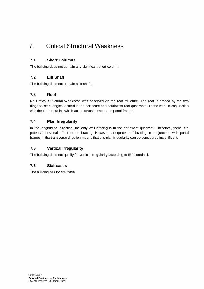
7. Critical Structural Weakness
7.1 Short Columns
The building does not contain any significant short column.
7.2 Lift Shaft
The building does not contain a lift shaft.
7.3 Roof
No Critical Structural Weakness was observed on the roof structure. The roof is braced by the two
diagonal steel angles located in the northeast and southwest roof quadrants. These work in conjunction
with the timber purlins which act as struts between the portal frames.
7.4 Plan Irregularity
In the longitudinal direction, the only wall bracing is in the northwest quadrant. Therefore, there is a
potential torsional effect to the bracing. However, adequate roof bracing in conjunction with portal
frames in the transverse direction means that this plan irregularity can be considered insignificant.
7.5 Vertical Irregularity
The building does not qualify for vertical irregularity according to IEP standard.
7.6 Staircases
The building has no staircase.

51/30596/67/
Detailed Engineering Evaluations Styx Mill Reserve Equipment Shed
8. Geotechnical Consideration
8.1 Site Description
The Styx Mill Conservation Reserve is situated in Harewood, Christchurch. The reserve is flat at 10m
above mean sea level and it’s approximately 4km south of the Waimakariri River, and 7km west of the
coast.
8.2 Published Information on Ground Conditions
8.2.1 Published Geology
The geological map of the area1 indicates that the site is underlain by:
grey river alluvium beneath plains or low-level terraces (Q1a), Holocene in age.
8.2.2 Environment Canterbury Logs
Information from Environment Canterbury (ECan) indicates that a number of boreholes are located
within a 200m radius of the site.
Of these boreholes, only one had lithographic logs (see Table 3), which indicate the area is typically
underlain by clay in the shallow part, followed by the gravel.
Table 2 ECan Borehole Summary
Bore Name Log Depth Groundwater Distance & Direction from Site
M35/5525 8.8m 1.1m bgl 100m N of the site
It should be noted that the purpose of the boreholes the well logs are associated with, were sunk for
groundwater extraction and not for geotechnical purposes. Therefore, the amount of material recovered
and available for interpretation and recording will have been variable at best and may not be
representative. The logs have been written by the well driller and not a geotechnical professional or to a
standard. In addition strength data is not recorded.
8.2.3 EQC Geotechnical Investigations
The Earthquake Commission has not undertaken geotechnical testing in the area of the subject site.
8.2.4 Land Zoning
Canterbury Earthquake Recovery Authority (CERA) has not published any information for this site.
1 Forsyth P.J., Barrell D.J.A., & Jongens R. 2008: Geology of the Christchurch Area. Institute of Geological and Nuclear Sciences
1:250,000 Geological Map 16. Lower Hutt. Institute of Geological and Nuclear Sciences Limited.

51/30596/67/
Detailed Engineering Evaluations Styx Mill Reserve Equipment Shed
8.2.5 Post February Aerial Photography
Aerial photography taken following the 22 February 2011 earthquake doesn’t show the clear signs of
liquefaction, as shown in Figure 3.
Figure 3 Post February 2011 Earthquake Aerial Photography 2
8.2.6 Summary of Ground Conditions
From the information presented above, it is anticipated that ground conditions at the subject site
comprise alluvial deposits. However, limited information on particle sizes or density was readily
available.
8.3 Seismicity
8.3.1 Nearby Faults
There are many faults in the Canterbury region, however only those considered most likely to have an
adverse effect on the site are detailed below.
2 Aerial Photography Supplied by Coordinates sourced from http://koordinates.com/layer/3185-christchurch-post-earthquake-
aerial-photos-24-feb-2011/
Equipment shed

51/30596/67/
Detailed Engineering Evaluations Styx Mill Reserve Equipment Shed
Table 3 Summary of Known Active Faults 3,4
Known Active Fault Distance from Site
Direction from Site
Max Likely Magnitude
Avg Recurrence Interval
Alpine Fault 130 km NW ~8.3 ~300 years
Greendale (2010) Fault 30 km SW 7.1 ~15,000 years
Hope Fault 100 km N 7.2~7.5 120~200 years
Kelly Fault 110 km NW 7.2 150 years
Porters Pass Fault 60 km NW 7.0 1100 years
Recent earthquakes since 22 February 2011 have identified the presence of a previously unmapped
active fault system underneath Christchurch City and the Port Hills. Research and published information
on this system is in development and not generally available. Average recurrence intervals are yet to be
estimated.
8.3.2 Ground Shaking Hazard
This seismic activity has produced earthquakes of Magnitude-6.3 with peak ground accelerations (PGA)
up to twice the acceleration due to gravity (2g) in some parts of the city. This has resulted in widespread
liquefaction throughout Christchurch.
New Zealand Standard NZS 1170.5:2004 quantifies the Seismic Hazard factor for Christchurch as 0.30,
being in a moderate to high earthquake zone. This value has been provisionally upgraded recently (from
0.22) to reflect the seismicity hazard observed in the earthquakes since 4 September 2010.
In addition, anticipation of marine and/or estuarine sands of varying density, a 475-year PGA (peak
ground acceleration) of ~0.4 (Stirling et al, 20023), and bedrock anticipated to be in excess of 500m
deep, and hence ground shaking is likely to be relatively high.
8.3.3 Slope Failure and/or Rockfall Potential
Given the site’s location, a flat suburb in northeast Christchurch, global slope instability is considered
negligible. However, any localised retaining structures or embankments should be further investigated to
determine the site-specific slope instability potential.
8.3.4 Liquefaction Potential
It is not clear from the post-earthquake aerial photography (Figure 3) whether liquefaction has occurred
at the site.
Ground investigation should be undertaken to better understand the liquefaction potential of the site and
allow a liquefaction assessment to be undertaken.
3 Stirling, M.W, McVerry, G.H, and Berryman K.R. (2002) A New Seismic Hazard Model for New Zealand, Bulletin of the
Seismological Society of America, Vol. 92 No. 5, pp 1878-1903, June 2002. 4 GNS Active Faults Database

51/30596/67/
Detailed Engineering Evaluations Styx Mill Reserve Equipment Shed
8.4 Recommendations
A soil class of D/E (in accordance with NZS 1170.5:2004) should be adopted for the site. The soil class
can be confirmed following assessment of adequate intrusive ground investigation information.
It is recommended that one machine-drilled borehole and two piezocone CPT investigations be
conducted to target depth of 20m. This will allow a liquefaction assessment to be undertaken.
8.5 Conclusions & Summary
This assessment is based on a review of the geology and existing ground investigation information, and
observations from the Christchurch earthquakes since 4 September 2010. However, limited ground
information was available for the subject site.
It is recommended that intrusive investigation comprising one machine-drilled borehole and two
piezocone CPTs should be conducted to target depth of 20m.

51/30596/67/
Detailed Engineering Evaluations Styx Mill Reserve Equipment Shed
9. Survey
No level or verticality survey has been undertaken for this building at this stage in accordance with
Christchurch City Council guidelines.

51/30596/67/
Detailed Engineering Evaluations Styx Mill Reserve Equipment Shed
10. Initial Capacity Assessment
10.1 % NBS Assessment
The building’s capacity was assessed using the Initial Evaluation Procedure based on the information
available. The building’s capacity is expressed as a percentage of new building standard (%NBS) and is
in the order of that shown below. This capacity is subject to confirmation by a more detailed quantitative
analysis which is more detailed.
Item %NBS
Building’s seismic capacity (No CSW observed) 85
Following an IEP assessment, the building has been assessed as achieving 85% New Building
Standard (NBS). Under the New Zealand Society for Earthquake Engineering (NZSEE) guidelines the
building is not considered a potential Earthquake Risk as it achieves greater than 67% NBS.
10.2 Seismic Parameters
The seismic design parameters based on current design requirements from NZS1170:2002 and the
NZBC clause B1 for this building are:
Site soil class: E, NZS 1170.5:2004, Clause 3.1.3, Very soft soil
Site hazard factor, Z = 0.3, NZBC, Clause B1 Structure, Amendment 11 effective from 1 August
2011
Return period factor Ru = 1.0, NZS 1170.5:2004, Table 3.5, Importance level 2 structure with a 50
year design life.
Several key seismic parameters that have influenced the %NBS score obtained from the IEP
assessment. An increased Z factor of 0.3 for Christchurch has been used in line with recommendations
from the Department of Building and Housing recommendations resulting in a reduced % NBS score.
10.3 Expected Structural Ductility Factor
A structural ductility factor of 3.0 has been assumed. This is based on the steel portal frame system
observed in both directions.
10.4 Discussion of Results
The original building was constructed in 1999 and was likely designed to the loading standard current at
the time, NZS 4203:1992. The design loads used in this standard are likely to have been less than those
required by the current loading standard. When combined with the increase in the hazard factor for
Christchurch to 0.3 and soil class E for very soft site, it would be expected that the building would not
achieve 100% NBS.
10.5 Occupancy
The building does not pose an immediate risk to users and occupants as no collapse hazards have been
identified.

51/30596/67/
Detailed Engineering Evaluations Styx Mill Reserve Equipment Shed
11. Initial Conclusions
The building has been assessed to have a seismic capacity in the order of 85% NBS and is therefore
not a potentially Earthquake Risk.

51/30596/67/
Detailed Engineering Evaluations Styx Mill Reserve Equipment Shed
12. Recommendations
It is recommended that:
a) As the building does not have any apparent damage and has achieved over 67% NBS following an
initial IEP assessment, the building can remain occupied as per Christchurch City Council’s policy.
b) No detailed quantitative assessment and strengthening option is required.

51/30596/67/
Detailed Engineering Evaluations Styx Mill Reserve Equipment Shed
13. Limitations
13.1 General
This report has been prepared subject to the following limitations:
No intrusive structural investigations have been undertaken.
No intrusive geotechnical investigations have been undertaken.
No level or verticality surveys have been undertaken.
No material testing has been undertaken.
No calculations have been performed, other than those included as part of the IEP in the CERA
Building Evaluation to be used for their purposes only. GHD accepts no responsibility for any other
party or person who relies on the information contained in this report.
It is noted that this report has been prepared at the request of Christchurch City Council and is intended
to be used for their purposes only. GHD accepts no responsibility for any other party or person who
relies on the information contained in this report.
13.2 Geotechnical Limitations
This report presents the results of a geotechnical appraisal prepared for the purpose of this commission,
and prepared solely for the use of Christchurch City Council and their advisors. The data and advice
provided herein related only to the project and structures described herein and must be reviewed by a
competent geotechnical engineer before being used for any other purpose. GHD Limited (GHD) accepts
no responsibility for other use of the data.
The advice tendered in this report is based on a visual geotechnical appraisal. No subsurface
investigations have been conducted. An assessment of the topographical land features have been made
based on this information. It is emphasised that geotechnical conditions may vary substantially across
the site from where observations have been made. Subsurface conditions, including groundwater levels
can change in a limited distance or time. In evaluation of this report cognisance should be taken of the
limitations of this type of investigation.
An understanding of the geotechnical site conditions depends on the integration of many pieces of
information, some regional, some site specific, some structure specific and some experienced based.
Hence this report should not be altered, amended or abbreviated, issued in part and issued incomplete
in any way without prior checking and approval by GHD. GHD accepts no responsibility for any
circumstances, which arise from the issue of the report, which have been modified in any way as
outlined above.

51/30596/67/
Detailed Engineering Evaluations Styx Mill Reserve Equipment Shed
Appendix A
Photographs

51/30596/67/
Detailed Engineering Evaluations Styx Mill Reserve Equipment Shed
Photo 1 Aerial photograph showing location of Styx Mill Reserve Equipment Shed.
Photo 2 Equipment Shed (Northeast elevation).
N
Equipment shed
Note: Other houses have been built since this photo was produced.

51/30596/67/
Detailed Engineering Evaluations Styx Mill Reserve Equipment Shed
Photo 3 Equipment Shed (Northwest elevation).
Photo 4 Equipment Shed (Southeast elevation).

51/30596/67/
Detailed Engineering Evaluations Styx Mill Reserve Equipment Shed
Photo 5 Equipment Shed (South elevation).
Photo 6 Equipment Shed (West elevation).

51/30596/67/
Detailed Engineering Evaluations Styx Mill Reserve Equipment Shed
Photo 7 View of the roof structure.
Photo 8 View of the diagonal roof bracing.

51/30596/67/
Detailed Engineering Evaluations Styx Mill Reserve Equipment Shed
Photo 9 View of corrugated metal walls.
Photo 10 View of partition between Equipment Room and Ranger’s Office.

51/30596/67/
Detailed Engineering Evaluations Styx Mill Reserve Equipment Shed
Appendix B
Existing Drawings

51/30596/67/
Detailed Engineering Evaluations Styx Mill Reserve Equipment Shed
Appendix C
CERA Building Evaluation Form

Detailed Engineering Evaluation Summary Data V1.11
Location
Building Name: Equipment Shed Reviewer: Stephen Lee
Unit No: Street CPEng No: 1006840
Building Address: Styx Mill Reserve 130 Hussey Road, Harewood Company: GHD
Legal Description: Lot 6 DP 29040 Company project number: 513059667
Company phone number: (03) 3780900
Degrees Min Sec
GPS south: Date of submission: 05/10/2012
GPS east: Inspection Date: 17/04/2012
Revision:
Building Unique Identifier (CCC): PRK 0340_BLDG_004 EQ2 Is there a full report with this summary? yes
Site
Site slope: flat Max retaining height (m):
Soil type: mixed Soil Profile (if available):
Site Class (to NZS1170.5): E
Proximity to waterway (m, if <100m): If Ground improvement on site, describe:
Proximity to clifftop (m, if < 100m):
Proximity to cliff base (m,if <100m): Approx site elevation (m):
Building
No. of storeys above ground: 1 single storey = 1 Ground floor elevation (Absolute) (m):
Ground floor split? no Ground floor elevation above ground (m):
Storeys below ground 0
Foundation type: Strip footing if Foundation type is other, describe:
Building height (m): 4.0 height from ground to level of uppermost seismic mass (for IEP only) (m):Floor footprint area (approx): 97
Age of Building (years): 13 Date of design: 1992-2004
Strengthening present? no If so, when (year)?
And what load level (%g)?
Use (ground floor): other (specify) Brief strengthening description:
Use (upper floors):
Use notes (if required):
Importance level (to NZS1170.5): IL2
Gravity Structure
Gravity System: frame system
Roof: steel framed rafter type, purlin type and cladding
Timber purlins with corrugated steel
sheetsFloors: concrete flat slab slab thickness (mm) approximately 100mm
Beams: steel non-composite beam and connector type I-sections
Columns: steel non-composite typical dimensions (mm x mm) I-sections
Walls: Timber girts with steel cladding & diagonal bracing Clad with corrugated steel sheets

Lateral load resisting structure
Lateral system along: Steel braced frame note total length of wall at ground (m): 5
Ductility assumed, m: 3.0 wall thickness (m):
Period along: 0.17 estimate or calculation?
Total deflection (ULS) (mm): estimate or calculation?
maximum interstorey deflection (ULS) (mm): estimate or calculation?
Lateral system across: Steel moment frame note typical frame sizes and bay length (m) 4.5
Ductility assumed, m: 3.0
Period across: 0.40 estimate or calculation?
Total deflection (ULS) (mm): estimate or calculation?
maximum interstorey deflection (ULS) (mm): estimate or calculation?
Separations:
north (mm): leave blank if not relevant
east (mm):
south (mm):
west (mm):
Non-structural elements
Stairs:
Wall cladding: Corrugated steel sheets describe (note cavity if exists)
Roof Cladding: Corrugated steel sheets
Glazing:
Ceilings:
Services(list):
Available documentation
Architectural partial original designer name/date
Structural partial original designer name/date
Mechanical none original designer name/date
Electrical none original designer name/date
Geotech report none original designer name/date
Damage
Site: Site performance: Good Describe damage:
(refer DEE Table 4-2)
Settlement: none observed notes (if applicable):
Differential settlement: none observed notes (if applicable):
Liquefaction: none apparent notes (if applicable):
Lateral Spread: none apparent notes (if applicable):
Differential lateral spread: none apparent notes (if applicable):
Ground cracks: none apparent notes (if applicable):
Damage to area: none apparent notes (if applicable):
Note: Define along and across in
detailed report!

Building:
Current Placard Status: No placard in place
Along Damage ratio: 0% Describe how damage ratio arrived at:
Describe (summary): No apparent damage observed
Across Damage ratio: 0%
Describe (summary): No apparent damage observed
Diaphragms Damage?: no Describe:
CSWs: Damage?: no Describe:
Pounding: Damage?: no Describe:
Non-structural: Damage?: no Describe:
Recommendations
Level of repair/strengthening required: none Describe:
Building Consent required: no Describe:
Interim occupancy recommendations: full occupancy Describe:
Along Assessed %NBS before: 85% 85% %NBS from IEP below
Assessed %NBS after: 85%
Across Assessed %NBS before: 85% 85% %NBS from IEP below
Assessed %NBS after: 85%
IEP Use of this method is not mandatory - more detailed analysis may give a different answer, which would take precedence. Do not fill in fields if not using IEP.
Period of design of building (from above): 1992-2004 hn from above: m
Seismic Zone, if designed between 1965 and 1992: not required for this age of building
Design Soil type from NZS4203:1992, cl 4.6.2.2: b) Intermediate
along across
Period (from above): 0.17 0.4
(%NBS)nom from Fig 3.3: 22.3% 22.3%
Note:1 for specifically design public buildings, to the code of the day: pre-1965 = 1.25; 1965-1976, Zone A =1.33; 1965-1976, Zone B = 1.2; all else 1.0 1.0
Note 2: for RC buildings designed between 1976-1984, use 1.2 1.0
Note 3: for buildngs designed prior to 1935 use 0.8, except in Wellington (1.0) 1.0
along across
Final (%NBS)nom: 22.3% 22.3%
2.2 Near Fault Scaling Factor Near Fault scaling factor, from NZS1170.5, cl 3.1.6: 1.00
along across
Near Fault scaling factor (1/N(T,D), Factor A: 1 1
If IEP not used, please detail
assessment methodology:
)(%
))(%)((%_
beforeNBS
afterNBSbeforeNBSRatioDamage

2.3 Hazard Scaling Factor Hazard factor Z for site from AS1170.5, Table 3.3: 0.30
Z1992, from NZS4203:1992 0.8
Hazard scaling factor, Factor B: 2.67
2.4 Return Period Scaling Factor Building Importance level (from above): 2
Return Period Scaling factor from Table 3.1, Factor C: 1.0
along across
2.5 Ductility Scaling Factor Assessed ductility (less than max in Table 3.2) 3.0 3.0
Ductility scaling factor: =1 from 1976 onwards; or =km, if pre-1976, fromTable 3.3: 1 1
Ductiity Scaling Factor, Factor D: 1.00 1.00
2.6 Structural Performance Scaling Factor: Sp: 0.70 0.70
Structural Performance Scaling Factor Factor E: 1.43 1.43
2.7 Baseline %NBS, (NBS%)b = (%NBS)nom x A x B x C x D x E %NBSb: 85% 85%
Global Critical Structural Weaknesses: (refer to NZSEE IEP Table 3.4)
3.1. Plan Irregularity, factor A: insignificant 1
3.2. Vertical irregularity, Factor B: insignificant 1
3.3. Short columns, Factor C: insignificant 1
3.4. Pounding potential Pounding effect D1, from Table to right 1.0
Height Difference effect D2, from Table to right 1.0
Therefore, Factor D: 1
3.5. Site Characteristics insignificant 1
Along Across
3.6. Other factors, Factor F For 3 storeys, max value =2.5, otherwise max valule =1.5, no minimum 1.0 1.0
Rationale for choice of F factor, if not 1
Detail Critical Structural Weaknesses: (refer to DEE Procedure section 6)
List any: Refer also section 6.3.1 of DEE for discussion of F factor modification for other critical structural weaknesses
3.7. Overall Performance Achievement ratio (PAR) 1.00 1.00
4.3 PAR x (%NBS)b: PAR x Baselline %NBS: 85% 85%
4.4 Percentage New Building Standard (%NBS), (before) 85%
Official Use only:
Accepted By
Date:
Table for selection of D1 Severe Significant Insignificant/none
Separation 0<sep<.005H .005<sep<.01H Sep>.01H
Alignment of floors within 20% of H 0.7 0.8 1
Alignment of floors not within 20% of H 0.4 0.7 0.8
Table for Selection of D2 Severe Significant Insignificant/none
Separation 0<sep<.005H .005<sep<.01H Sep>.01H
Height difference > 4 storeys 0.4 0.7 1
Height difference 2 to 4 storeys 0.7 0.9 1
Height difference < 2 storeys 1 1 1

51/30596/67/
Detailed Engineering Evaluations Styx Mill Reserve Equipment Shed
GHD
Level 11, Guardian Trust House
15 Willeston street, Wellington 6011
T: 64 4 472 0799 F: 64 4 472 0833 E: [email protected]
© GHD Limited 2012
This document is and shall remain the property of GHD Limited. The document may only be used for the
purpose for which it was commissioned and in accordance with the Terms of Engagement for the
commission. Unauthorised use of this document in any form whatsoever is prohibited.
Document Status
Rev No. Author Reviewer Approved for Issue
Name Signature Name Signature Date
Final R. Ramilo Stephen Lee
Nick Waddington
31/10/12