
Styles 009N and 009H FireLock EZ Rigid Couplings
4
I-009N/009H I-009N/009H INSTALLATION INSTRUCTIONS REV_H Styles 009N and 009H FireLock EZ ™ Installation-Ready ™ Rigid Couplings WARNING • Read and understand all instructions before attempting to install any Victaulic piping products. • Depressurize and drain the piping system before attempting to install, remove, adjust, or maintain any Victaulic piping products. • Wear safety glasses, hardhat, and foot protection. Failure to follow these instructions could result in death or serious personal injury and property damage. INSTRUCTIONS FOR THE INITIAL INSTALLATION OF STYLE 009N/009H COUPLINGS DO NOT REMOVE NUTS/BOLTS FOR INITIAL INSTALLATION 1. DO NOT DISASSEMBLE THE COUPLING: Style 009N/009H FireLock EZ ™ Installation-Ready ™ Rigid Couplings are designed so that the installer does not need to remove the bolts and nuts for installation. This design facilitates installation by allowing the installer to directly insert the grooved end of mating components into the coupling. 2. CHECK MATING COMPONENT ENDS: The outside surface of the mating component, between the groove and the mating component end, must be smooth and free from indentations, projections, weld seams, and roll marks to ensure a leak-tight seal. All oil, grease, loose paint, dirt, and cutting particles must be removed. The mating component OD, groove dimensions, and maximum allowable flare diameter must be within the tolerances published in current Victaulic grooving specifications. NOTE: Maximum allowable mating component ovality shall comply with the requirements of ASTM A-999 and API 5L. Greater variations between the major and minor mating component diameters will result in difficult coupling assembly. Gasket Grade Color Code Mark 3. CHECK GASKET: Check the gasket to make sure it is suitable for the intended service. The color code identifies the gasket grade. Refer to Victaulic publication 05.01 in the G-100 General Catalog for the color code chart. 3a. REFER TO THE NOTICE IN THE FOLLOWING COLUMN FOR IMPORTANT GASKET INFORMATION. NOTICE • Victaulic Style 009N/009H Couplings are designed for use ONLY on wet and dry fire protection systems (temperatures greater than –40°F/–40°C). For rigid pipe connections in systems continuously operating below 0°F/–18°C, Victaulic recommends Style 005 FireLock ™ Rigid Couplings with Grade “L” (silicone) FlushSeal ™ gaskets. • Victaulic Style 009N/009H Couplings are provided with the Vic-Plus gasket system. Additional lubrication is not required for the initial installation of wet pipe systems that are installed at or continuously operating above 0°F/–18°C. Refer to Victaulic publication 05.03 in the G-100 General Catalog for the Vic-Plus MSDS sheet. Supplemental lubrication is required for Vic-Plus gaskets only if any of the following conditions exist. If any of these conditions exist, apply a thin coat of Victaulic lubricant or silicone lubricant to the sealing lips of the gasket interior only. • If the gasket has been exposed to fluids prior to installation • If the surface of the gasket does not have a hazy appearance • If the gasket is being installed into a dry pipe system • If the system will be subjected to air tests prior to being filled with water • If the gasket was involved in a previous installation • If the gasket sealing surface of the pipe contains raised or undercut weld seams, or cracks or voids at the weld seams. However, lubricated gaskets may not enhance sealing capabilities on all adverse pipe conditions. Pipe condition and pipe preparation must conform to the requirements listed in product installation instructions. WARNING • Never leave a Style 009N/009H Coupling partially assembled. A partially assembled Style 009N/009H Coupling poses a drop hazard or a burst hazard during testing. • Keep hands away from the mating component ends and the openings of the coupling when attempting to insert the grooved mating component ends into the coupling. Failure to follow these instructions could result in serious personal injury and/or property damage.
Transcript of Styles 009N and 009H FireLock EZ Rigid Couplings

I-009N/009H
I-009N/009HINSTALLATION INSTRUCTIONS
REV_H
Styles 009N and 009H FireLock EZ™ Installation-Ready™ Rigid Couplings
WARNING
• Read and understand all instructions before attempting to install any Victaulic piping products.
• Depressurize and drain the piping system before attempting to install, remove, adjust, or maintain any Victaulic piping products.
• Wear safety glasses, hardhat, and foot protection.
Failure to follow these instructions could result in death or serious personal injury and property damage.
INSTRUCTIONS FOR THE INITIAL INSTALLATION OF STYLE 009N/009H COUPLINGS
DO NOT REMOVE NUTS/BOLTS FOR
INITIAL INSTALLATION
1. DO NOT DISASSEMBLE THE COUPLING: Style 009N/009H FireLock EZ™ Installation-Ready™ Rigid Couplings are designed so that the installer does not need to remove the bolts and nuts for installation. This design facilitates installation by allowing the installer to directly insert the grooved end of mating components into the coupling.
2. CHECK MATING COMPONENT ENDS: The outside surface of the mating component, between the groove and the mating component end, must be smooth and free from indentations, projections, weld seams, and roll marks to ensure a leak-tight seal. All oil, grease, loose paint, dirt, and cutting particles must be removed. The mating component OD, groove dimensions, and maximum allowable flare diameter must be within the tolerances published in current Victaulic grooving specifications. NOTE: Maximum allowable mating component ovality shall comply with the requirements of ASTM A-999 and API 5L. Greater variations between the major and minor mating component diameters will result in difficult coupling assembly.
Gasket Grade Color Code Mark
3. CHECK GASKET: Check the gasket to make sure it is suitable for the intended service. The color code identifies the gasket grade. Refer to Victaulic publication 05.01 in the G-100 General Catalog for the color code chart.
3a. REFER TO THE NOTICE IN THE FOLLOWING COLUMN FOR IMPORTANT GASKET INFORMATION.
NOTICE
• Victaulic Style 009N/009H Couplings are designed for use ONLY on wet and dry fire protection systems (temperatures greater than –40°F/–40°C). For rigid pipe connections in systems continuously operating below 0°F/–18°C, Victaulic recommends Style 005 FireLock™ Rigid Couplings with Grade “L” (silicone) FlushSeal™ gaskets.
• Victaulic Style 009N/009H Couplings are provided with the Vic-Plus gasket system. Additional lubrication is not required for the initial installation of wet pipe systems that are installed at or continuously operating above 0°F/–18°C. Refer to Victaulic publication 05.03 in the G-100 General Catalog for the Vic-Plus MSDS sheet.
Supplemental lubrication is required for Vic-Plus gaskets only if any of the following conditions exist. If any of these conditions exist, apply a thin coat of Victaulic lubricant or silicone lubricant to the sealing lips of the gasket interior only.
• If the gasket has been exposed to fluids prior to installation
• If the surface of the gasket does not have a hazy appearance
• If the gasket is being installed into a dry pipe system
• If the system will be subjected to air tests prior to being filled with water
• If the gasket was involved in a previous installation
• If the gasket sealing surface of the pipe contains raised or undercut weld seams, or cracks or voids at the weld seams. However, lubricated gaskets may not enhance sealing capabilities on all adverse pipe conditions. Pipe condition and pipe preparation must conform to the requirements listed in product installation instructions.
WARNING
• Never leave a Style 009N/009H Coupling partially assembled. A partially assembled Style 009N/009H Coupling poses a drop h azard or a burst hazard during testing.
• Keep hands away from the mating component ends and the openings of the coupling when attempting to insert the grooved mating component ends into the coupling.
Failure to follow these instructions could result in serious personal injury and/or property damage.
I-009N/009H_2 REV_H
I-009N/009H / Styles 009N and 009H FireLock EZ™ Installation-Ready™ Rigid Couplings / Installation Instructions
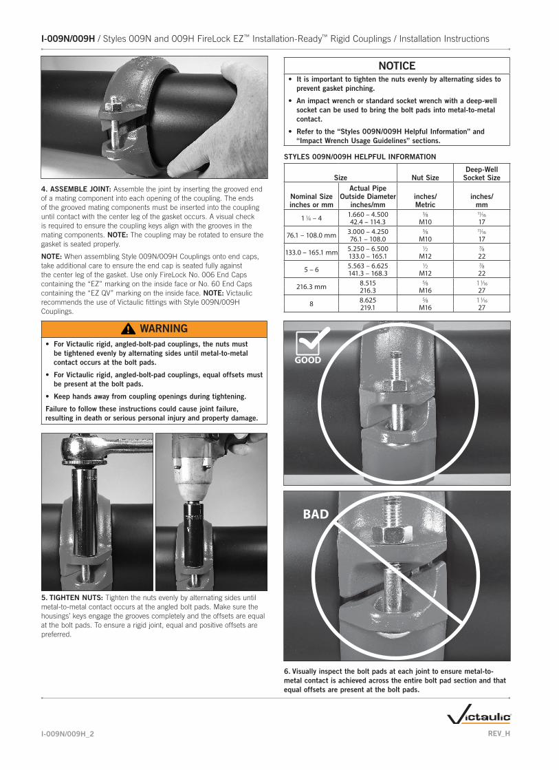
4. ASSEMBLE JOINT: Assemble the joint by inserting the grooved end of a mating component into each opening of the coupling. The ends of the grooved mating components must be inserted into the coupling until contact with the center leg of the gasket occurs. A visual check is required to ensure the coupling keys align with the grooves in the mating components. NOTE: The coupling may be rotated to ensure the gasket is seated properly.
NOTE: When assembling Style 009N/009H Couplings onto end caps, take additional care to ensure the end cap is seated fully against the center leg of the gasket. Use only FireLock No. 006 End Caps containing the “EZ” marking on the inside face or No. 60 End Caps containing the “EZ QV” marking on the inside face. NOTE: Victaulic recommends the use of Victaulic fittings with Style 009N/009H Couplings.
WARNING• For Victaulic rigid, angled-bolt-pad couplings, the nuts must
be tightened evenly by alternating sides until metal-to-metal c ontact occurs at the bolt pads.
• For Victaulic rigid, angled-bolt-pad couplings, equal offsets must be present at the bolt pads.
• Keep hands away from coupling openings during tightening.
Failure to follow these instructions could cause joint failure, resulting in death or serious personal injury and property damage.
5. TIGHTEN NUTS: Tighten the nuts evenly by alternating sides until metal-to-metal contact occurs at the angled bolt pads. Make sure the housings’ keys engage the grooves completely and the offsets are equal at the bolt pads. To ensure a rigid joint, equal and positive offsets are preferred.
NOTICE• It is important to tighten the nuts evenly by alternating sides to
prevent gasket pinching.
• An impact wrench or standard socket wrench with a deep-well socket can be used to bring the bolt pads into metal-to-metal contact.
• Refer to the “Styles 009N/009H Helpful Information” and “Impact Wrench Usage Guidelines” sections.
STYLES 009N/009H HELPFUL INFORMATION
Size Nut SizeDeep-Well
Socket Size
Nominal Sizeinches or mm
Actual Pipe Outside Diameter
inches/mminches/Metric
inches/mm
1 1/4 – 4 1.660 – 4.500 3/8 11/1642.4 – 114.3 M10 17
76.1 – 108.0 mm 3.000 – 4.250 3/8 11/1676.1 – 108.0 M10 17
133.0 – 165.1 mm 5.250 – 6.500 1/2 7/8133.0 – 165.1 M12 22
5 – 6 5.563 – 6.625 1/2 7/8141.3 – 168.3 M12 22
216.3 mm 8.515 5/8 1 1/16216.3 M16 27
8 8.625 5/8 1 1/16219.1 M16 27
GOOD
BAD
6. Visually inspect the bolt pads at each joint to ensure metal-to-metal contact is achieved across the entire bolt pad section and that equal offsets are present at the bolt pads.
I-009N/009H_3REV_H
I-009N/009H / Styles 009N and 009H FireLock EZ™ Installation-Ready™ Rigid Couplings / Installation Instructions
WARNING• Visual inspection of each joint is critical.
• Improperly assembled joints must be corrected before the system is placed in service.
Failure to follow these instructions could cause joint failure, resulting in death or serious personal injury and property damage.
GOOD BAD
PROPERLY ASSEMBLED JOINT
POSITIVE OFF-SET WITH BOLT PAD CONTACT (PREFERRED)
PROPERLY ASSEMBLED
JOINT
NEUTRAL OFFSET WITH BOLT PAD
CONTACT
IMPROPERLY ASSEMBLED
JOINT
NEGATIVE OFFSET
IMPROPERLY ASSEMBLED
JOINT
BOLT PAD GAP
• “Negative” bolt pad offsets can occur when the nuts are not tightened evenly, which produces over-tightening of one side and under-tightening of the other side. In addition, “negative” offsets can occur if both nuts are under-tightened.
INSTRUCTIONS FOR RE-INSTALLATION OF STYLE 009N/009H COUPLINGS
WARNING• Make sure the system is depressurized and
drained completely before attempting to disassemble any couplings.
Failure to follow this instruction could result in death or serious personal injury and property damage.
1. Make sure the system is depressurized and drained completely before attempting to disassemble any couplings.
2. Follow steps 2 – 3 of the “Instructions for the Initial Installation of Style 009N/009H Couplings” section. Inspect the gasket for any damage or wear. If any damage or wear is present, replace the gasket with a new Victaulic-supplied gasket of the same grade.
CAUTION• A compatible lubricant must be used to prevent the gasket from
pinching/tearing during re-installation.
Use of an incompatible lubricant will cause gasket degradation, resulting in joint leakage and property damage.
3. FOR RE-INSTALLATION OF STYLE 009N/009H COUPLINGS, LUBRICATE GASKET: Apply a thin coat of Victaulic Lubricant or silicone lubricant to the gasket sealing lips and exterior. It is normal for the gasket surface to have a hazy white appearance after it has been in service.
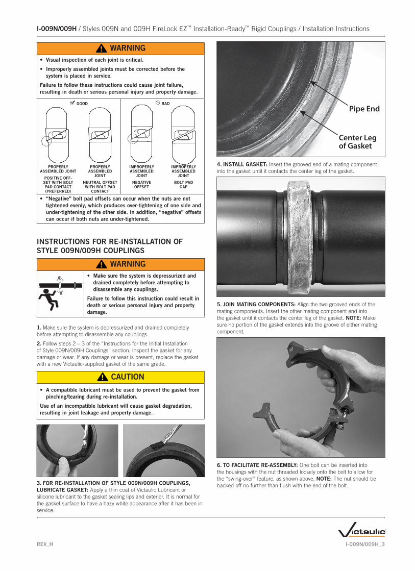
Pipe End
Center Leg of Gasket
4. INSTALL GASKET: Insert the grooved end of a mating component into the gasket until it contacts the center leg of the gasket.
5. JOIN MATING COMPONENTS: Align the two grooved ends of the mating components. Insert the other mating component end into the gasket until it contacts the center leg of the gasket. NOTE: Make sure no portion of the gasket extends into the groove of either mating component.
6. TO FACILITATE RE-ASSEMBLY: One bolt can be inserted into the housings with the nut threaded loosely onto the bolt to allow for the “swing-over” feature, as shown above. NOTE: The nut should be backed off no further than flush with the end of the bolt.

I-009N/009HINSTALLATION INSTRUCTIONS
Styles 009N and 009H FireLock EZ™ Installation-Ready™ Rigid Couplings
For complete contact information, visit victaulic.comI-009N/009H 4079 REV H UPDATED 11/2014 Z000009000VICTAULIC, FIRELOCK EZ, INSTALLATION-READY, FIRELOCK, AND FLUSHSEAL ARE TRADEMARKS OR REGISTERED TRADEMARKS OF VICTAULIC COMPANY AND/OR ITS AFFILIATED ENTITIES IN THE UNITED STATES AND/OR OTHER COUNTRIES. © 2014 VICTAULIC COMPANY. ALL RIGHTS RESERVED.
7. INSTALL HOUSINGS: Install the housings over the gasket. Make sure the housings’ keys engage the grooves properly on both mating components.
8. INSTALL REMAINING BOLT/NUT: Install the remaining bolt, and thread the nut finger-tight onto the bolt. NOTE: Make sure the oval neck of each bolt seats properly in the bolt hole.
9. TIGHTEN NUTS: Follow steps 5 – 6 of the “Instructions for the Initial Installation of Style 009N/009H Couplings” section to complete the assembly.
IMPACT WRENCH USAGE GUIDELINES
WARNING
• It is important to tighten the nuts evenly by alternating sides until metal-to-metal c ontact occurs at the bolt pads.
• For rigid, angled-bolt-pad couplings, even offsets must be present at the bolts pads.
• DO NOT continue to tighten the nuts after the visual installation guidelines for the coupling are achieved.
Failure to follow these instructions could cause gasket pinching and coupling damage, resulting in joint failure, serious personal injury, and property damage.
Due to the speed of assembly when using an impact wrench, the installer should take extra care to ensure nuts are tightened evenly by alternating sides until proper assembly is complete. Always refer to the specific product installation instructions for complete installation requirements.
Impact wrenches do not provide the installer with direct “wrench feel” or torque to judge nut tightness. Since some impact wrenches are capable of high output, it is important to develop a familiarity with the impact wrench to avoid damaging or fracturing the bolts or the coupling bolt pads during installation. DO NOT continue to tighten the nuts after the visual installation guidelines for the coupling are achieved.
If the battery is drained or if the impact wrench is under-powered, a new impact wrench or a new battery pack must be used to ensure the visual installation guidelines for the coupling are achieved.
Perform trial assemblies with the impact wrench and check the assemblies with socket or torque wrenches to help determine the capability of the impact wrench. Using the same method, periodically check additional nuts throughout the system installation.
For safe and proper use of impact wrenches, always refer to the impact wrench manufacturer’s operating instructions. In addition, verify that proper impact grade sockets are being used for coupling installation.
WARNINGFailure to follow instructions for tightening coupling hardware could result in:
• Bolt fractures
• Damaged or broken bolt pads or coupling fractures
• Joint leakage