Stuffing, Stacking and Lashing Containers - ukpandi.com Documents... · This survey report will...
32
393 Chapter 41 Stuffing, Stacking and Lashing Containers There are three main categories of damage to cargo shipped by container: 1. The consignee receives the container with a broken seal. In such circumstances, the carrier may be held liable for damage and/or loss to the cargo. The safety measure from the carrier’s point of view, therefore, should be to ensure they reject any containers found with a damaged/broken seal at the load port. In theory, the seal must be checked at each stage in the logistic chain where a container exchanges hands. If found and unreported, the next entity in the chain who finds the broken seal may claim for damages from the previous one. It must be borne in mind at all times that a broken seal may mean more than damage or loss of cargo; it may also mean that criminals have introduced illicit items such as drugs or even humans into the container. The carrier is advised, therefore, to report any broken seal to the shipper as well as to their P&I Club. A survey may be appropriate
-
Upload
truongkien -
Category
Documents
-
view
315 -
download
5
Transcript of Stuffing, Stacking and Lashing Containers - ukpandi.com Documents... · This survey report will...

393
Chapter 41
Stuffing, Stacking and Lashing Containers
There are three main categories of damage to cargo shipped by container:
1. The consignee receives the container with a broken seal. In such circumstances, the carrier may be held liable for damage and/or loss to the cargo.
The safety measure from the carrier’s point of view, therefore, should be to ensure they reject any containers found with a damaged/broken seal at the load port.
In theory, the seal must be checked at each stage in the logistic chain where a container exchanges hands. If found and unreported, the next entity in the chain who finds the broken seal may claim for damages from the previous one. It must be borne in mind at all times that a broken seal may mean more than damage or loss of cargo; it may also mean that criminals have introduced illicit items such as drugs or even humans into the container. The carrier is advised, therefore, to report any broken seal to the shipper as well as to their P&I Club. A survey may be appropriate
Carefully to Carry Consolidated Edition 2018
394
to establish any pilferage, loss or damage to the cargo, after which the container may be allowed for shipment.
2. The container and the cargo is damaged. In such a case, a joint survey by the shipper or consignee and the carrier (P&I Club) will be carried out to establish the extent of damage. This survey report will define the liability for both parties.
Cou
rtes
y of
New
Zea
land
Def
ence
For
ce
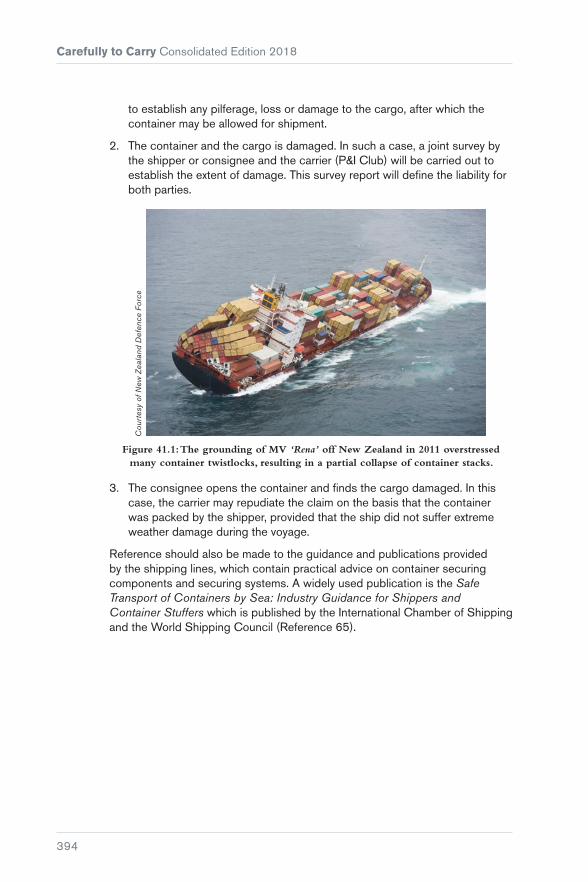
Figure 41.1: The grounding of MV ‘Rena’ off New Zealand in 2011 overstressed many container twistlocks, resulting in a partial collapse of container stacks.
3. The consignee opens the container and finds the cargo damaged. In this case, the carrier may repudiate the claim on the basis that the container was packed by the shipper, provided that the ship did not suffer extreme weather damage during the voyage.
Reference should also be made to the guidance and publications provided by the shipping lines, which contain practical advice on container securing components and securing systems. A widely used publication is the Safe Transport of Containers by Sea: Industry Guidance for Shippers and Container Stuffers which is published by the International Chamber of Shipping and the World Shipping Council (Reference 65).

Chapter 41 Stuffing, Stacking and Lashing Containers
395
Front wall panel
LHS sidewall panel
Roof panel
Rear endDoor header
LHS top rear corner casting
Hinge
Rod guide
Cam end guide
Cam end
Door
Cam keeper
Door sealing gasket
Lever
Rear sill
RHS bottom rear corner casting
RHS door corner postor RHS rear corner post
Floor
Bottom cross member(floor supports)
Bottom side rail skirt
Bottom side rail
Front RHScorner post
Front sill
Top side rail
Front header
Front end
Cou
rtes
y of
Hap
ag L
loyd
Figure 41.2: Components of a container.
41.1 Stuffing
Containers are often packed at places that are distant from the marine loading terminal, sometimes several days’ journey. It is, therefore, important that everyone involved with the packing of containers, at whatever stage in transit, is fully aware of the stresses that can be generated in the structure of the container itself and in the cargo within it. It is essential that containers are in sound structural condition each time they are put into service and that they are suitable for the cargo to be carried.
It should always be borne in mind that the side panels, end panels and roof panels of an ISO container are not normally strength members.
Beneath the floor timbers, there are metal cross bearers and it is generally these bearers that provide the floor’s strength. Additionally, the corner posts, front and rear headers, and front and rear sills provide the internal strength members. Whenever bracing is to be used in vertical, horizontal or diagonal form, it must act against those members and the floor bearers and no others. Bracing and/or end chocking against side, end and roof panels will result in disaster.
Unlike breakbulk cargo, the ship’s Master and officers do not sight, or have any control over, the contents of containers or the methods by which the contents have been packed and secured.
Carefully to Carry Consolidated Edition 2018
396
If the contents of just one container are improperly packed, lack adequate securing arrangements or are inappropriate for container carriage, they may break adrift when the ship encounters heavy weather, risking the safety of the other containers, their contents and the ship itself.
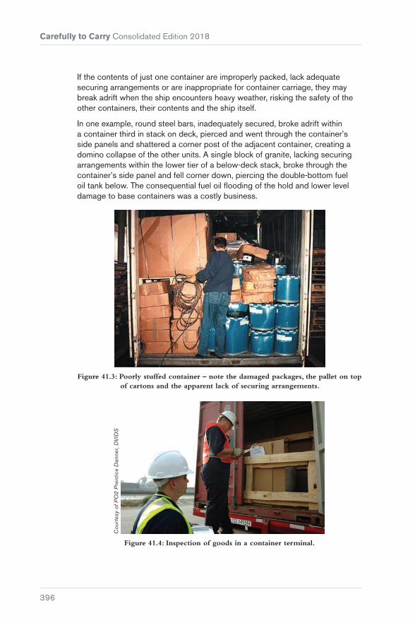
In one example, round steel bars, inadequately secured, broke adrift within a container third in stack on deck, pierced and went through the container’s side panels and shattered a corner post of the adjacent container, creating a domino collapse of the other units. A single block of granite, lacking securing arrangements within the lower tier of a below-deck stack, broke through the container’s side panel and fell corner down, piercing the double-bottom fuel oil tank below. The consequential fuel oil flooding of the hold and lower level damage to base containers was a costly business.
Figure 41.3: Poorly stuffed container – note the damaged packages, the pallet on top of cartons and the apparent lack of securing arrangements.
Cou
rtes
y of
PO
2 P
rent
ice
Dan
ner,
DV
IDS
Figure 41.4: Inspection of goods in a container terminal.

Chapter 41 Stuffing, Stacking and Lashing Containers
397
Figure 41.5: Damage caused to a container by poorly secured coils.
Casualty investigation often reveals that horizontal spaces, ie fore-and-aft and longitudinally, are generally adequately chocked, but the vertical component is entirely neglected. When a ship is pitching and yawing in a seaway, vertical acceleration and deceleration forces acting on cargo components can attain values of 2 g, which means that, as the vessel goes up and comes down, the load on the securing arrangements will be equal to twice the static weight of the cargo item. If there is no arrangement to secure the cargo to the floor of the container, the cargo will lift, and once it lifts it will start to shift, and once it starts to shift it will go on shifting!
up to 1.0 g
up to 1.0 g
up to 1.0 g
up to 2.0 g
up to 0.5 g
up to 0.5 g
up to 0.4 g
up to 0.4 g
up to 0.8 g
up to 0.8 g
Figure 41.6: Potential accelerations at sea.
Where relatively lightweight cartons or good timber cases can be afforded tight block stowage, there will be little need for additional securing arrangements. However, where plastic jars, bottles, barrels or lightweight cartons with frail contents are to be stowed to the full internal height, it may be necessary to provide mid-height flooring so that the lowermost items do not suffer compression damage or collapse.
Carefully to Carry Consolidated Edition 2018
398
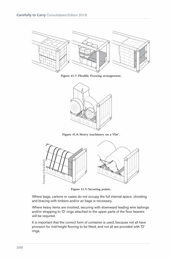
Figure 41.7: Flexible f looring arrangement.
Figure 41.8: Heavy machinery on a ‘f lat’.
Cou
rtes
y of
Sca
nDut
ch
Figure 41.9: Securing points.
Where bags, cartons or cases do not occupy the full internal space, chocking and bracing with timbers and/or air bags is necessary.
Where heavy items are involved, securing with downward leading wire lashings and/or strapping to ‘D’ rings attached to the upper parts of the floor bearers will be required.
It is important that the correct form of container is used, because not all have provision for mid-height flooring to be fitted, and not all are provided with ‘D’ rings.
Chapter 41 Stuffing, Stacking and Lashing Containers
399
Steel coils, steel pipes and bars, and heavy machinery items should be shipped on specially designed ‘flat racks’, ‘flats’ or ‘sledges’ (see Figure 41.7). These units are strengthened for such loads and adequate securing terminal points are provided (see Figures 41.8 and 41.9).
41.2 Container Stuffing Considerations
The packing and securing of goods inside a container plays a vital role in safe transportation of goods to their destination, but this is never in the control of the ship’s officers. In some ports, some carriers require container stuffing to be sample checked to ensure that the contents, particularly if there are any dangerous goods, have been secured properly.
Further inspections of the goods may also be made by the harbour or customs authorities to establish customs duties and export taxes, etc and, where this is done, the carriers can utilise the opportunity to check the stuffing of cargoes.
The ship’s officers must play their role in observing and reporting any abnormalities. Consideration should be given to the following.
1. Cargo may be containerised for a prolonged period, during which changes in temperature may lead to generation of mould, bacteria, fungus or other microorganisms, particularly where the cargoes are hygroscopic and there is a lack of proper ventilation. To avoid biological contamination, many countries require containers to be fumigated and then sealed prior to shipment.
2. When different commodities are stuffed together, the compatibility characteristics of each cargo should be noted. Some examples of non-compatible cargoes are:
a) cargoes that emit odours stowed with odour sensitive cargoes
b) hygroscopic cargoes stowed with cargoes that may absorb moisture. If unavoidable, hygroscopic cargoes should be loaded under other cargoes with a layer of dunnage and a protective cover such as a tarpaulin laid on top of the hygroscopic cargo.
3. Hygroscopic cargoes are likely to give off moisture during transportation leading to condensation, commonly referred to as ‘container sweat’ or ‘container rain’. Condensation may damage the cargo and may lead to biological contamination. Desiccants may be provided, but these are not a failsafe means of preventing condensation.
4. Certain sensitive cargoes, such as wet hides or salted skins, require containers to be lined with plastic sheeting or packing paper.

Carefully to Carry Consolidated Edition 2018
400
5. Containers are fitted with lashing/securing points with the longitudinal beams on the floor or roof and also with the corner posts. Each lashing point has a predetermined SWL (safe working load), which is generally 1 t but may vary for older containers. Container walls are not designed to be load bearing, so nothing should be attached to them.
6. When palletised cargo is loaded into a container, the space utilisation will depend on the size of the pallet in relation to the size of the container. Generally, there will be some void spaces between pallets and these must be filled in with air/inflatable bags or dunnage. Where pallets are stowed more than one high, their longitudinal movement within the container must also be blocked by the use of appropriate lashing or chocking.
7. Distribution of weight within a container should avoid:
a) Loading heavier items at one end or side of the container
b) Stowing heaver items above light items. Impact on the centre of gravity of the container with respect to weight distribution should also be considered.
8. Cargo items with sharp edges, protrusions or awkward shape must not be stowed next to soft packages, to avoid damage during even the smallest movement within the cargo.
9. Any cargo that is liable to leak should not be stowed on top of other cargo.
41.3 Containers in Stack
Most ISO containers are designed to allow nine-high stacking when empty. They should be placed and must stand on the four lower and four upper corner castings alone, with the appropriate stacking/locking components between. The bottom and top side rails, the front and rear sills and headers, and the underside floor bearers should remain free of vertical stacking contact at all times if transient wracking stresses are to be avoided.
There are many different securing systems and problems may arise if ships’ officers/charterers’ superintendents are unfamiliar with a specific system.
Container stack racking failures may occur in non-purpose-built vessels if charterers insist on stacking containers in the holds and on the weather deck in a manner that would not be approved even in a purpose-built ship. Unfortunately, stack collapses within the holds, and within weather-deck stacks, occur just as frequently in purpose-built vessels.

Chapter 41 Stuffing, Stacking and Lashing Containers
401
Container stack failures generally arise from three causes that involve unacceptable racking stresses in one form or another:
� Substandard components and seaworthiness
� weight management problems in stacks
� mixed unit sizes.
41.3.1 Substandard Components and Cargoworthiness
A vessel’s container stowage and securing arrangement can easily be undermined if substandard and/or incorrect components are utilised. Maintaining securing equipment in good order, both fixed and portable, requires considerable time and effort.
Whatever regulations, standards or codes of practice are issued, the integrity of a vessel’s container stowage and securing arrangement can only be ensured by regular inspection of the securing equipment. The securing arrangement can be undermined by one or more of the following:
� ‘Rogue’ securing equipment
� improperly maintained securing equipment
� complacency in inspection of the equipment and record keeping
� insufficient supply of correct securing equipment
� overloading of the securing equipment.
Portable securing equipment
If substandard equipment is used, it can fail at a lower load than its design rating, thereby resulting in failure of the overall securing system and possible collapse of the container stow.
The following aspects should be considered during periodic inspection of container securing equipment:
� Inspection of the twistlock complement to ensure that rogue twistlocks, ie ones with an opposite locking action to the ship’s standard complement, have not made their way on board. When left-hand and right-hand locking twistlocks are fitted with similar shaped handles, which can be the case, it is not always possible to differentiate between them once used in the same stow. Even if the stevedores are aware of the difference, any subsequent checks by other people could allow disengagement if the handles are all actuated in the same direction on the premise that some twistlocks had not been properly locked in the first instance.
ISO Standard 3874, Series 1 freight containers – handling and securing, includes the physical and functional requirements for various items of portable securing equipment as an appendix to the standard itself

Carefully to Carry Consolidated Edition 2018
402
(Reference 66). ISO Standard 1161, Series 1 freight containers – corner and intermediate fittings establishes the basic dimensions and the functional and strength requirements of corner and intermediate fittings for series 1 freight containers (Reference 67).
For manual twistlocks, it is proposed that the unified direction of handling will be clockwise when viewed from above, ie lefthand locking
� checks to ensure that the spring holding the twistlock in the closed position is in a resilient condition. If a spring loses its resiliency, the cone(s) will not be held in position in a positive manner. The moving and flexing of a vessel in a seaway has been found sufficient to allow twistlocks to unlock themselves if their spring action is failing or has failed
Figure 41.10: Uniform twistlocks.
� check to ensure there are no structural defects that would compromise the proper use of the equipment, for example:
� twistlocks with missing handles
� twistlocks with fractured housings
� double cones with fractured base plates
� seized/buckled turnbuckles, bridge fittings.
Figure 41.11: Fixed fittings.

Chapter 41 Stuffing, Stacking and Lashing Containers
403
Regular inspection of fixed fittings is also essential to establish whether progressive wear has undermined their integrity. Areas requiring particular attention include:
� Reduction in the thickness of securing points where for example a turnbuckle may have chafed
� wastage in the way of the key holes of deck foundations
� wastage and cracking of the plating to which fittings are welded
� distortion of dovetail deck foundations.
If a dovetail type fitting and its associated part are compatible and in good working order, it should only be possible to slide a dovetail type twistlock or locating cone in a horizontal direction into the deck fitting. However, if the deck fitting is damaged or its associated part is incompatible, it may be possible to lift a dovetail type twistlock or locating cone out vertically. In such an event, no vertical restraint will be provided to secure a column of containers to the deck.
Figure 41.12: Worn shoe fitting.
41.3.2 Weight Management Problems in Stacks
Cou
rtes
y of
Dan
ny C
orne
lisse
n/po
rtpi
ctur
es.n
l
Figure 41.13: The stacking of containers.

Carefully to Carry Consolidated Edition 2018
404
The most potentially damaging stacking problem occurs when heavyweight containers are loaded into the upper tiers of container bays on deck.
The problem can occur with any container ship if the permissible stack/tier weights are ignored for a specific securing arrangement. For example, modern container ships feature deck stows comprising six or seven tiers of units, which appears to represent a huge carrying capacity. However, weight limits apply and, in the upper tiers (sixth and seventh layers), only empty containers may be carried.
The operating principle is that the weights of containers should not exceed the prescribed limits for the slots in which they are stowed. These limits should be set according to stack weight, tier position and the securing arrangement being used. In modern container handling systems, the loading model for a particular class of vessel is usually sufficiently well detailed that it prevents an operator from planning the loading of a heavy container in a light slot. In a more sophisticated approach, the loading computer will calculate, on an individual stack basis, the resultant forces acting upon the containers and the lashing system. A maximum container weight will be determined for each position and it is possible that a heavy container could be received over a unit of lesser weight, provided that securing loads are acceptable. In both examples, if the weight is excessive for the specified position, the computer program will simply reject the container.
However, the container industry covers a broad spectrum and vessels that incorporate the very latest technology run side by side with others from older generations. In all cases, it is the responsibility of the ship planning coordinator and/or the loading terminal ship planner to stow the containers into the proper and appropriate positions on the ship.
Another reason for exceeding the stack loads may be misdeclared weights by the shippers. As a consequence of continued accidents resulting from this, and pressure from the shipping industry, the IMO amended SOLAS Regulation VI/2 requiring shippers to weigh containers prior to shipping and provide verification to the carrier about the total mass of each container.
The verified gross mass of a container is the total gross mass of a packed container, which is obtained by either of the following methods:
� Weighing the container after packing and sealing it
� weighing all packages, dunnage, pallets and securing materials to be stuffed in a container and adding them to the tare mass of the container.
Upon receipt of verification of the gross mass of the container, the shipper must communicate it to the carrier (and Master) via a shipping document. It should be noted that the obligation is for the shipper to provide the verified gross mass to the carrier, shipping company and the Master. The role of the ship planner in ensuring compliance with this is crucial.

Chapter 41 Stuffing, Stacking and Lashing Containers
405
Under legislation laid down by the United States Department of Labor’s Occupational Safety and Health Administration (29 CFR 1917.71 Marine Terminals: Terminals handling intermodal container or roll-on roll-off operations) (Reference 68), all cargo containers must be weighed before being hoisted for loading. Empty containers must be checked to ensure that they are indeed empty and marked or noted as such.
Figure 41.14: Collapsed container stacks as a result of bad stowage.
Bad stowage can occur as a result of a mistake, or it may be due to complacency. The following are the main reasons why heavy containers are sometimes placed in the wrong slots:
� Inexperience An inexperienced planner faced with a problem of container distribution might simply allocate stowage on the ‘best possible’ basis, ignoring good stowage principles and the vessel’s stowage and securing criteria.
� insufficient knowledge A planner who lacks specific knowledge of the tier limits for a particular vessel, or class of vessel, will not know whether a particular plan he has composed meets the criteria of the vessel’s lashing system. Lack of coordination between the planners and the lashing teams may not take into account the added complications resulting from the need for sufficient strength of lashing for heavy stows.
� late arrivals Errors often occur when containers are received late for shipment. The vessel may be part loaded and stevedores may have abandoned a scheduled loading plan in place of a hybrid because cargo was not available when the vessel arrived. When containers arrive late, it may be the case that only relatively high positions remain available.
� third party stowage. In almost all cases, loading, stowage and securing of containers is carried out by third party stevedores with the ship’s officers and crew only able to monitor their work. The quick operation of modern container gantries and the large number of containers being loaded/discharged in a short period of time mean that the ship’s crew is physically unable to pay the

Carefully to Carry Consolidated Edition 2018
406
same attention as they would otherwise on a smaller container with slower cargo operations. This situation has been historically complicated by lack of proper access to the top of container stacks to place, for example, the stacking cones or to properly lock the twistlocks. While some of these functions remain restricted due to the quick turnaround of container ships combined with the large volume of cargo being loaded, some of the issues can be overcome by the crew’s due diligence. MSC.1/Circ.1353, published in December 2014, requires that a cargo safe access plan (CSAP) is supplied within the cargo securing manual to ensure that persons engaged in securing and stowage of containers are provided with safe access during their work. This plan details guidance for hand rails, platforms, walkways, ladders, storage facilities, fittings for specialised containers such as reefer plugs, first aid locations and any other information that may be relevant to provision of safe access.
Addressing the issue on board ship
Ships’ staff should not allow loading operations to commence until they have received a copy of the proposed stowage plan. A relatively quick inspection should show whether heavy containers have been planned over light ones and whether the stack and tier weights are within the permissible limits.
Vigilance is the key and ships’ staff should be aware that mistakes are often accompanied by departures from the plan. Duty officers must not hesitate to report to the chief officer on any occasion when stevedores advise there is a change to the original plan and the chief officer should look carefully at what is proposed.
Ships’ staff should always check the pre-loading plan for heavy container stacks. These should be identified and, if possible, the container numbers in these stacks checked during loading. If a different container appears in the upper tier, it may be a heavy unit stowed by mistake and of sufficient weight to overload the stack and the lashing system.
Problems that may be created by incorrect stowage of this type include:
� The need for restowage of containers (and resulting delays and costs) if an overweight condition is ascertained
� collapsed container stacks
� containers lost overboard (both the overweights and containers that were not overweight)
� cargo liability claims
� chassis damage

Chapter 41 Stuffing, Stacking and Lashing Containers
407
� damage to the vessel
� stability and stress risks for the vessel
� risk of personal injury or death to seafarers and shoreside workers
� last minute shut-outs of confirmed, booked and available loads when the actual weight on board exceeds what is declared and the total cargo weight exceeds the vessel limit or port draught limit.
Container ship operators must instruct terminals to check weight against stowage slot before allowing a unit to be shipped late in a position other than that originally planned. In most cases, the plan will be sufficiently flexible to accommodate late loading, but in some instances it will not. Potential problems must be identified, and remedied, before sailing.
The most common method by which a stowage error of this type is discovered is when the chief officer updates his loading plan using the final plan, normally provided electronically. The update should tell him whether there are any changes from the pre-load plan. In more extreme cases, the discovery is made when the vessel encounters moderate weather and starts to roll and pitch. The safety margins in lashing systems are very small and an excessively heavy stack will soon begin to challenge the integrity of the securing arrangements. Container structures will be overloaded, causing fittings to fail and movement to occur.
On a modern vessel, the breakdown of the stowage usually commences in lower tiers, possibly at second tier level, where racking loads may cause failure of the door end structure. Alternatively, the compressive forces may cause buckling of a post. There may be excessive pull-out loads on twistlocks or base locks.
Once fittings have begun to fail, movement of the stack occurs and load is transferred to adjacent stacked containers and, in most cases, an entire bay of containers is at risk. Outcomes where heavy containers have been loaded in high positions have involved:
� The loss overboard and subsequent compulsory recovery of dangerous chemicals in 200 m water depths
� the capsize of ships alongside a berth
� the collapse of stacks and spillage of hazardous chemicals on deck.
Case studies
The loading of a container ship is a complex process. Weight must be evenly distributed at the same time as ensuring that hazardous cargoes are positioned appropriately and away from other cargoes with which they might react. There have been several instances where ships have capsized or heeled to severe angles during loading or unloading.

Carefully to Carry Consolidated Edition 2018
408
‘Deneb’
In June 2011, the container ship ‘Deneb’ capsized at the Port of Algeciras during loading operations. There had been modifications to the stowage plan during loading because of safety concerns and, during the first part of loading, a heel of 10° was seen. As the final containers were being loaded, the ship listed to approximately 45°, resulting in the ship lying on the pier. Further listing was in progress when tugs managed to push the ship further onto the pier to avoid a total capsize. It is believed that this accident was due to the weights of containers being incorrectly declared.
‘Repubblica di Genova’
In March 2007, the ‘Repubblica di Genova’ capsized as it was being loaded, while in berth at Antwerp. This ship was a RoRo vessel but was carrying a number of containers on deck. The cause was never determined, but a number of reports suggested that some of the containers on deck were heavier than had been declared and caused the ship to list to one side, eventually capsizing. The ship was partially under water for six months before salvage could be completed, at which point the ship underwent a total renovation and then returned to service.
41.3.3 Mixed Unit Sizes
Another cause of stack failure is where two 20 ft units are stowed on the weather deck in what would otherwise be a 40 ft unit position, making it very difficult, and sometimes impossible, to apply wires, chains or lashing bars to the adjacent end-butting corners. Their absence is not compensated for by using double or four-way inter-layer stackers (spades) or longitudinally positioned screw-bridge fittings, tie-wires or the like (see Figure 41.15).
Figure 41.15: Adjacent corner castings should never be loop-lashed.
The container stack as a whole, and particularly units in the base tier, will be subject to excessive racking stresses should the ship start rolling in heavy seas or pronounced swell conditions. Some compensation can be applied by the use of anti-rack bands (two tensioned metal straps fitted diagonally across the
Chapter 41 Stuffing, Stacking and Lashing Containers
409
corners of the ‘free’ ends of the base tier containers) but they suffer from the same inability to secure the ‘butting’ ends. Sometimes, anti-rack spacers are used (see Figure 41.16), but a full lashing system is preferred.
Figure 41.16: Anti-rack spacer.
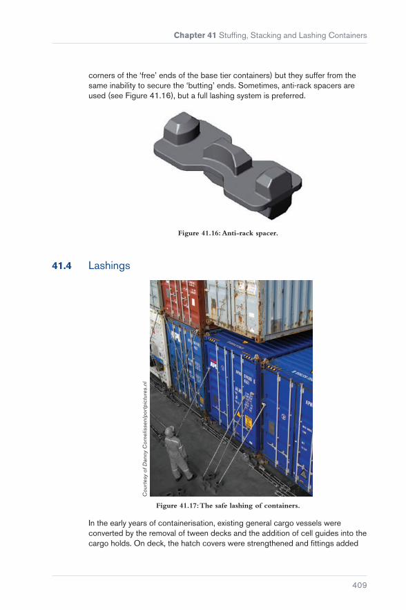
41.4 Lashings
Cou
rtes
y of
Dan
ny C
orne
lisse
n/po
rtpi
ctur
es.n
l
Figure 41.17: The safe lashing of containers.
In the early years of containerisation, existing general cargo vessels were converted by the removal of tween decks and the addition of cell guides into the cargo holds. On deck, the hatch covers were strengthened and fittings added
Carefully to Carry Consolidated Edition 2018
410
for lashings. However, the containers on deck were seldom stowed above one high and so were secured to the vessel by ‘traditional’ cargo ship methods.
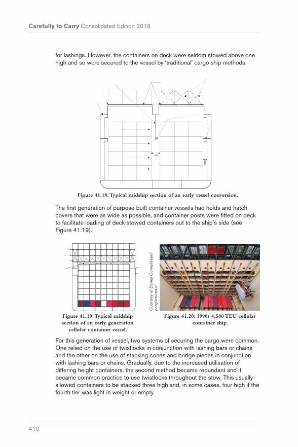
Figure 41.18: Typical midship section of an early vessel conversion.
The first generation of purpose-built container vessels had holds and hatch covers that were as wide as possible, and container posts were fitted on deck to facilitate loading of deck-stowed containers out to the ship’s side (see Figure 41.19).
Figure 41.20: 1990s 4,500 TEU cellular container ship.
Figure 41.19: Typical midship section of an early generation
cellular container vessel.
Cou
rtes
y of
Dan
ny C
orne
lisse
n/po
rtpi
ctur
es.n
l
For this generation of vessel, two systems of securing the cargo were common. One relied on the use of twistlocks in conjunction with lashing bars or chains and the other on the use of stacking cones and bridge pieces in conjunction with lashing bars or chains. Gradually, due to the increased utilisation of differing height containers, the second method became redundant and it became common practice to use twistlocks throughout the stow. This usually allowed containers to be stacked three high and, in some cases, four high if the fourth tier was light in weight or empty.
Chapter 41 Stuffing, Stacking and Lashing Containers
411
For first generation vessels, computer technology was not available on board to speedily calculate dynamic loads acting on container lashings and frames. The shipboard computer was only used to calculate stresses and stability for the ship itself. Therefore, shipboard staff would ensure the vessel was lashed according to a lashing plan taken from the lashing equipment manufacturer’s manual, which tended to assume an ideal stow with respect to the distribution of weight in each stack.
With further development in the industry, the size of container ships continued to grow, with 9-high stowage in holds and 4-high stowage on deck becoming commonplace, and the industry began to realise that standards in lashing were required. Ships were at this stage still supplied with loading computers to calculate the ship’s stability, shear forces, bending and, occasionally, torsion moments. Very few had the capability to calculate dynamic loads on container frames and lashing systems caused by ship motions and wind forces, so the lashings were still applied throughout the stow in accordance with the manufacturer’s manual.
Following incidents such as the loss of the MOL ‘Comfort’, the question has been asked whether the sheer size of these ships constitutes a risk. If a fire broke out on one of these ships, potentially millions of pounds worth of cargo is at risk and there is a relatively small number of crew available to try to get any such situation under control.
While the economies of scale demand larger container ships, the lashing systems in use on all types of container vessels are very similar and based on the twistlock and lashing bar/turnbuckle system. Large hatch openings mean that containers are partly resting on hatch covers and partly on stanchions located adjacent to the hatchway, but unequal deformities in the hull structure may lead to misalignment of container seating points. Even though the Classification Society rules provide for certain allowance in any such misalignments, the extent of these will vary between ships and, in some cases, on the same ship between various stowage locations. This will have an impact on the stresses placed on lashings and, therefore, the resulting outcomes with respect to their ability to hold a container in position.
On post-Panamax vessels, where among other features the vessel’s large beam results in an unavoidable, relatively large GM (metacentric height), the practice is for the vessel to be fitted with a lashing bridge, which is a substantial steel structure running athwartships between each 40 ft container bay. This allows the second and third tiers of containers to be secured to the bridge using lashing rods and turnbuckles, while the whole stow is secured throughout with twistlocks (see Figure 41.25). The lashing bridge allows the anchoring points for each stack to be moved higher up the stack, which allows the lashings to be more effective in reducing the tipping moments acting on a stack when a vessel is rolling heavily. However, the practice of fitting the bridges between 40 ft bays means that the 20 ft containers can only take advantage of the lashing bridges at one end. So, in effect, the 20 ft stacks have to revert to the limits of a conventional lashing system. This is because the practice of estimating the

Carefully to Carry Consolidated Edition 2018
412
Cou
rtes
y of
Car
gote
c
Figure 41.21: Lashing bridges.
forces acting on a stack divides the container weight equally between each end of the container. Therefore, the weight in each 20 ft container is limited by the capacity of the lashing system at the container end, which does not have the advantage of being secured by a lashing bridge.
Cou
rtes
y of
Car
gote
c
Figure 41.22: Top lashing bridge system for up to 9-high containers.

Chapter 41 Stuffing, Stacking and Lashing Containers
413
On smaller vessels, the whole stow is also secured throughout with twistlocks, and the lowest three tiers are secured to the hatch cover or support post using the lashing bar/turnbuckle combination (see Figure 41.27).
Modern vessels may have up to 9-high stowage on deck, and the use of onboard computers to check the dynamics of the stow in all weather conditions is vitally important for the safe carriage of the cargo. Development of ultra-large container ships (ULCS) has required ultra-secure lashing systems. The safety of containers on board not only depends on the speed at which modern container ships operate but also their direction of movement in relation to the height and direction of waves to control the ship’s rolling and pitching motion, and so stresses on the container lashings. This type of development, combined with modification of lashing equipment such as lift-away hatch covers, fully automatic twistlocks (FATs) and the use of modern computerised systems to check loads on lashing points and equipment combined with full assessment of ship stability, can provide a complete solution.
‘Napoli’ case study
In January 2006, the 276 m, 4,734 TEU container ship MSC ‘Napoli’ was deliberately beached in the English Channel during a strong storm after parts of the ship became flooded. It was discovered that the hull had suffered severe fractures, although the vessel remained in one piece.
The investigation determined that the hull fractures occurred because the vessel had insufficient buckling strength. Whipping and hogging in the high waves caused heavier than usual loads.
Cou
rtes
y of
the
MC
A
Figure 41.23: MSC ‘Napoli’.

Carefully to Carry Consolidated Edition 2018
414
Cou
rtes
y of
the
MC
A
Stern is liftedout of thewater
BendingMoment
Wave crest at amidships creates buoyancy
ShearingForces
Weight
Weight
Figure 41.24: MSC ‘Napoli’ – simulation of forces leading to hull fracture.
The use of a computer lashing program, together with the IMO requirement for every vessel to carry on board an approved cargo securing manual, should theoretically mean a reduction in collapsed stows and losses overboard, provided the operators maintain the lashing equipment and comply with the requirements of the manual. The vigilance of ships’ staff is, therefore, vital to ensure that lashings are applied correctly.
Cou
rtes
y of
Dan
ny C
orne
lisse
n/po
rtpi
ctur
es.n
l
Figure 41.25: Typical post-panamax lashing bridge arrangement
(shown 4 high).
Figure 41.26: Lashing a container to the lashing bridge.

Chapter 41 Stuffing, Stacking and Lashing Containers
415
Figure 41.27: Typical container vessel’s hatch cover lashing arrangement.
Figure 41.28: Tightening the turnbuckle.
Cou
rtes
y of
Dan
ny C
orne
lisse
n/po
rtpi
ctur
es.n
l
41.4.1 Requirements of Lashing Systems
Figure 41.29: Typical ‘on lid’ loading.

Carefully to Carry Consolidated Edition 2018
416
The requirement to carry a cargo securing manual is specified in:
� MSC.1/Circ.1352 (and MSC.1/Circ.1352/Rev.1) – Amendments to the Code of Safe Practice for Cargo Stowage and Securing (CSS Code) (Reference 69) given in MSC/Circ.745(17) (Reference 70) which amends the CSS Code and provides Guidance on Providing Safe Working Conditions
� MSC.1/Circ.1353 – Revised guidelines for the preparation of the Cargo Securing Manual, which apply to container ships whose keels were laid on or which were at a similar stage of construction before 1st January 2015 (Reference 24).
SOLAS Chapter VI: Regulation 5, Stowage and Securing states:
“Cargo, cargo units and cargo transport units carried on or under deck shall be so loaded, stowed and secured as to prevent as far as is practicable, throughout the voyage, damage or hazard to the ship and the persons on board, and loss of cargo overboard.”
It goes on to say that:
“Freight containers shall not be loaded to more than the maximum gross weight indicated on the Safety Approval Plate under the International Convention for Safe Containers (CSC), as amended.
“All cargoes, other than solid and liquid bulk cargoes, cargo units and cargo transport units, shall be loaded, stowed and secured throughout the voyage in accordance with the Cargo Securing Manual approved by the Administration. ( ... ) The Cargo Securing Manual shall be drawn up to a standard at least equivalent to relevant guidelines developed by the Organization.” (Reference 18)
Therefore, following MSC/Circ.745(17) (Reference 70), any Classification Society that approves a cargo securing manual will need to ensure the following:
� The guidance given in the cargo securing manual does not replace the experience in stowage and securing and the principles of good seamanship
� the information in the manual is consistent with the requirements of the vessel’s trim/stability and hull strength manual, the International Convention on Load Lines, 1966 (Reference 25) requirements and the International Maritime Dangerous Goods Code (IMDG Code) (Reference 19), where applicable
� the manual specifies arrangements and cargo securing devices provided on board for the correct application to the containers, based on transverse, longitudinal and vertical forces that may arise during adverse weather and sea conditions
� such securing arrangements and devices shall be suitable and adapted to the nature of the cargo to be carried and used properly with appropriate securing points or fittings

Chapter 41 Stuffing, Stacking and Lashing Containers
417
� there is a sufficient quantity of reserve cargo securing devices on board the ship
� the manual contains information on the strength and instructions for the use and maintenance of each specific type of cargo securing device
� the manual should be updated when new or alternative types of securing devices are introduced
� the manual should consist of a comprehensive and understandable plan, providing an overview of the maximum stack weights and permissible vertical distribution of weight in stacks
� the manual should present the distribution of accelerations expected at various positions on board the ship based on a range of GM values. This information should be accompanied by a worked example showing the angles of roll and GM above which the forces acting on cargo exceed permissible limits for securing devices along with examples of calculations for number and strength of securing devices to counteract the exceeded limits
� the manual should provide information on the forces induced by wind and sea on deck cargo, and on the nominal increase of forces or accelerations with an increase in GM
� the manual should contain recommendations for reducing the risk of cargo losses from deck stows, by applying restrictions to stack weights or heights where high stability cannot be avoided
� the cargo safe access plan (CSAP) should provide detailed information for the safety of persons engaged in work connected with cargo stowage and securing.
IMO/Circ.745(17) also states that the cargo securing devices should be maintained in a satisfactory condition and that items worn or damaged to such an extent that their quality is impaired should be replaced. It is commonly accepted that obligatory survey of portable fittings is not generally pursued by the Classification Society, and so inspection and replacement should be the responsibility of the operators/Masters. Any inspections, maintenance, repair or rejection of cargo securing devices should be recorded and kept with the cargo securing manual. When replacement securing devices are placed on board, they should be provided with appropriate certification.
Portable fittings should be certified by some form of type-approval system, usually coming from the manufacturer (when approved), a Classification Society or other accepted testing body.
Ship managers may request a Classification Society to approve their particular lashing system and the lashing program software, in addition to the requirement of approving the cargo securing manual. However, until the cargo securing manual and the computer lashing program are produced and approved

Carefully to Carry Consolidated Edition 2018
418
Figure 41.30: The accelerations acting on a container in a seaway.
Figure 41.31: Excessive tipping moment or separation force on
corner f ittings.
together, in the same way as the ship stability loading computer and stability/loading manual are already used, there is bound to be confusion with respect to the safe capabilities of the on-deck container lashing system for each ship.
One note of caution: different Classification Societies have set their own standards for the minimum SWLs of lashing gear and maximum allowable forces acting on a container and the roll angle that any calculations should include.
Types of lashing failure
In general terms, whenever a vessel is working in a seaway, it will incur three main movements, described as rolling, pitching and heaving. These give rise to accelerations, and therefore forces, that act on the container frames and lashing system in use. Figure 41.30 illustrates the ship motions experienced by a container stack.
Of the forces acting on an individual container and its lashings as a result of these movements, the separation force is the tipping force that acts to pull out or separate the corner fittings or twistlocks. When the vessel is rolling heavily, if the separation force is excessive, it may pull the twistlocks out of the corner castings of the container, break the twistlocks at their weakest point or separate the corner castings from the main body of the container.
When the vessel is rolling heavily, and containers stowed on higher tiers are heavy, a racking force will be produced in the frame of the lowest containers. The larger the roll of the vessel, the larger the racking force will be.

Chapter 41 Stuffing, Stacking and Lashing Containers
419
Figure 41.32: Excessive racking force on a container.
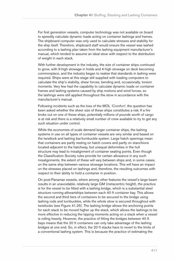
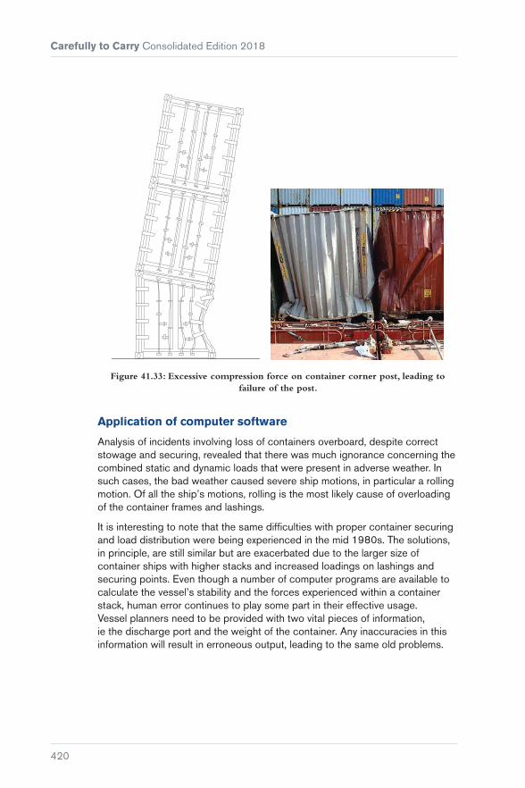
A large GM, particularly when coupled with a short roll period, increases the dynamic loadings caused by rolling, and all of the loads previously mentioned will increase the compression and tension forces acting at the corner posts of the containers and at the twistlocks between them. If excessive, they may result in structural failure of one or more of the corner posts (see Figure 41.33).
Carefully to Carry Consolidated Edition 2018
420
Figure 41.33: Excessive compression force on container corner post, leading to failure of the post.
Application of computer software
Analysis of incidents involving loss of containers overboard, despite correct stowage and securing, revealed that there was much ignorance concerning the combined static and dynamic loads that were present in adverse weather. In such cases, the bad weather caused severe ship motions, in particular a rolling motion. Of all the ship’s motions, rolling is the most likely cause of overloading of the container frames and lashings.
It is interesting to note that the same difficulties with proper container securing and load distribution were being experienced in the mid 1980s. The solutions, in principle, are still similar but are exacerbated due to the larger size of container ships with higher stacks and increased loadings on lashings and securing points. Even though a number of computer programs are available to calculate the vessel’s stability and the forces experienced within a container stack, human error continues to play some part in their effective usage. Vessel planners need to be provided with two vital pieces of information, ie the discharge port and the weight of the container. Any inaccuracies in this information will result in erroneous output, leading to the same old problems.
Chapter 41 Stuffing, Stacking and Lashing Containers
421
The situation is complicated when the chief officer, on behalf of the Master, continues to hold the responsibility for correct stowage and carriage of cargo but may not have enough time to study the information supplied by the planner to question any inaccuracies.
To aggravate the situation further, many ports supply the chief officer with an electronic bay-plan file of the pre-load plan, which should include all the relevant container data. Again, the onus is on the chief officer to check that the correct information about the container height and weight has been entered, as this affects the vessel’s stability and any calculation of the forces experienced within the stack.
The benefits of using a program include assistance in achieving safer carriage of deck-stowed containers, saving on lashing requirements in terms of employment of lashing gangs, and the possibility of loading more cargo (depending on the voyage). Lashing equipment must be in good condition and certified as suitable because the calculations assume that all containers and lashing materials are in good condition and that all lashings are correctly applied, with equal tension on lashing bars, etc. These programs also calculate a theoretical angle of roll that a ship should not exceed.
Forces within a stack are affected by all ship motions, but the angle of roll is normally the most critical. Classification Society regulations assume values, which are generally the default values in loading programs. The natural period of roll can be determined using the rule of thumb formula:
Period (TR ) = 0.7 BeamGM
A detailed breakdown of the forces in each stack will be provided by loading programs, which include:
Racking force
This is the transverse force that tends to distort the container ends, primarily due to a rolling action. It should not exceed a maximum allowable force (MAF) of 15 t. If a lashing is applied, the force varies between the forward and aft ends of the container because of the different stiffness of the door and closed ends.
Corner shear
This is closely related to racking force, but is the force that tends to shear off the twistlocks. It should not exceed an SWL of 15 t for a standard twistlock.
Compressive force
This is the force acting on the container corner posts and fittings, which results from tilting of the stack and the vertical acceleration. It should not exceed 45 t

Carefully to Carry Consolidated Edition 2018
422
for a standard 20 ft container corner post or 67.5 t for a 40 ft container corner post. Larger compression forces are allowed for corner castings at the base of a stack (83.8 t).
Separation force
This is the tipping force that is acting to pull out or separate the corner fittings. It should not exceed 15 t for the top fitting and 20 t for the bottom. This force does not refer to the tensile loadings on the twistlocks.
Lashing tension
This is the tension in the applied lashings. Lashing rods should only ever be applied hand tight, not overtightened with large spanners, as this induces unnecessary tension in the lashing rod, reducing the angle of roll at which the SWL would be exceeded. The Germanischer Lloyd (GL) limit for lashing rods is 23 t SWL; turnbuckles are rated at 18 t.
If a container or item of lashing equipment exceeds its SWL/maximum allowable force, this does not automatically mean that the item will fail. SWLs are mostly set at 50% of the breaking load. The use of an SWL is to give a safety margin, allowing for occasional overstressing. A container that has been highlighted as having exceeded the Class limits will not automatically be lost if the vessel rolls to 24.9°. However, while many container stacks remain on board after having suffered greater loadings than some of those lost, calculations cannot allow for the domino effect of an inboard stack collapsing, falling against its neighbour and inducing far greater forces upon it, which in turn causes collapse.
Correct application of lashing equipment is also important and one example of incorrect application of semi-automatic base twistlocks occurs when there is an element of fore and aft movement of the container immediately prior to landing it on board so the base locks tend to be placed in the deck fitting rather than the base of the container prior to loading.
Any fore and aft movement of the container as it is aligned over the base lock risks the actuating wire being caught under the container, rendering the twistlock inoperable unless the container is lifted and landed correctly. This highlights the necessity of continual vigilance by the ship’s staff during the loading process.

Chapter 41 Stuffing, Stacking and Lashing Containers
423
Figure 41.34: Twistlock failure. Figure 41.35: Unlocked twistlock.
41.5 Containers in the Holds of Conventional Ships and Bulk Carriers
The ongoing problem of collapse of unsecured container stacks in non-purpose-built holds provides ample evidence that such stacks will not stay in place on the basis of their total weight alone.
Firm securing of the stacks to the ship’s structure as a block is essential. If slackness develops during adverse weather conditions, the containers will chafe and rack, leading to overall distortion and possible collapse, particularly if heavy units have been placed in upper tiers.
ISO containers are designed to be carried by stacking them one above the other in slots or cells below deck and on the weather decks in purpose-built ships, or ships converted for such carriage. The design of bulk carriers appears to provide large, unobstructed spaces for the safe stowage of containers. They are, however, prone to severe stresses arising in a heavy seaway and containers carried in block stowages below decks can create problems if adequate securing measures are not adopted. It is not infrequent that an entire stow of containers collapses, with serious damage to the boxes and to the cargo within them.
Generally, the cargo compartments of bulk carriers are not of the right dimensions to enable the container stow to be a perfect fit. In vessels fitted with sloping hopper side tanks, for example, there will be a large area of unusable space between a block of containers and the ship’s sides. Adequate measures must be adopted to ensure that the containers, as a result of rolling stresses, will not move or collapse into these spaces.
Whenever possible, the containers should be formed into one solid rigid block so that there will be no movement whatsoever. The bottom containers in the stacks should be secured to the ship’s tank top plating by twistlocks

Carefully to Carry Consolidated Edition 2018
424
or lockable locator cones and, in addition, twistlocks or lockable inter-layer stackers should be used between each container in the stack.
Not all the containers in a block will be loaded or discharged at a single port and, as a consequence, there may be parts of a voyage when the block will be irregular rather than cuboid in shape. The stow must be fully resecured as omissions of this nature have been the prime cause of a number of casualties. In the absence of such precautionary measures, the stacking of containers two high or more will produce racking stresses, which tend to distort containers laterally.
This problem will be aggravated during heavy weather, when the weight of the containers in the upper part of the stow may cause the corner posts of the lower containers to buckle, with the inevitable result that the stow collapses. This is more likely to happen in the forward holds, where the effects of pounding are more pronounced. Ideally, all ships converting to the carriage of containers in stacks two or more high should have the securing system and the strengthening requirements for the tank tops approved by the Classification Society.
In some systems, the spaces between the containers and the sides of the holds are taken up with portable or hinged steel girder chocks that insert precisely into the corner castings of the various heights of containers. Alternatively, and in addition to the provision of any form of inter-layer stackers or twistlocks, solid bar or wire lashings may be required, tautened on turnbuckles hooked into securing points at the tank top and at higher levels adjacent to the ship’s shell plating.