Study Unit Clutches, Transmissions, and Drives - Indianmcinfo
53
Study Unit Clutches, Transmissions, and Drives By Ed Abdo
Transcript of Study Unit Clutches, Transmissions, and Drives - Indianmcinfo

Study Unit
Clutches,Transmissions,
and DrivesBy
Ed Abdo

This study unit focuses on the transmissions and related components used in motorcycle or ATVengines. In this study unit, you’ll learn about the different types of gears that you may find in amotorcycle or ATV engine. You’ll also understand how the primary drive and different clutchsystems function in an engine. We’ll then discuss how and why transmissions are used in motor-cycle and ATV engines.
When you complete this study unit, you’ll be able to
� Identify the different gears used in transmissions
� Calculate gear and drive ratios correctly
� Identify the functions of the primary drive systems
� Identify the different components that make up the primary drive systems
� Understand and identify the different clutch types
� Identify the different clutch release mechanisms
� Identify the different types of transmissions and shifting components
� Identify and understand the different types of final drive systems
Previewiii

03300800tc.txtINTRODUCTION . . . . . . . . . . . . . . . . . . . . . . . . . . . . . 1GearsGear Ratios
PRIMARY DRIVES. . . . . . . . . . . . . . . . . . . . . . . . . . . . . 9Gear-Driven Primary DriveChain-Driven Primary DriveBelt-Driven Primary Drive
CLUTCH SYSTEMS . . . . . . . . . . . . . . . . . . . . . . . . . . . . 10Manual ClutchCentrifugal ClutchVariable-Ratio ClutchSprag Clutch
SERVICE AND REPAIR OF CLUTCHES . . . . . . . . . . . . . . . . . . 20Common Clutch ProblemsClutch AdjustmentMultiplate Manual Clutch AdjustmentMultiplate Manual Clutch RepairAn Example Repair of a Typical Multiplate Manual Clutch
TRANSMISSIONS . . . . . . . . . . . . . . . . . . . . . . . . . . . . . 30Transmission GearsConstant-Mesh TransmissionsDual-Range TransmissionsShifting Transmission GearsIndirect-Drive Transmission Power FlowShifting MechanismsTransmission Problem SymptomsStarting Systems
FINAL DRIVE SYSTEMS . . . . . . . . . . . . . . . . . . . . . . . . . . 43Chain-Driven Final DrivesBelt-Driven Final DrivesShaft-Driven Final Drives
ROAD TEST ANSWERS . . . . . . . . . . . . . . . . . . . . . . . . . . 49
EXAMINATION . . . . . . . . . . . . . . . . . . . . . . . . . . . . . 51
Contentsv

INTRODUCTIONAll motorcycles and ATVs use some type of a drive system to propelthe vehicle. The primary drive, transmission, and final drive systemswork together to transfer the power that’s produced by the enginecrankshaft to the rear wheels. To use the power made at the enginecrankshaft, a motorcycle or ATV may use gears, belts, clutches,sprockets and a chain, or a combination of these items. Before welearn about the clutches, transmissions, and final drives used in mo-torcycles and ATVs, we must first understand some basic informationrelated to gears and gear ratios.
GearsA gear is simply one or more rotating levers. There are five primarypurposes for using gears in engines:
1. To transmit power from one shaft to another
2. To change the direction of rotation
3. To increase torque, which results in a decrease in the revolutionsper minute (rpm), or speed, of the gear; note that the force behinda moving gear is the torque of the drive system.
4. To increase rpm, which results in a decrease in torque
5. To properly time certain components in the engine such as en-gine balancers and camshafts on four-stroke engines
There are several basic types of gears used in an engine. Gears arealso used in other areas of a motorcycle and ATV. Because you’ll seemany different types of gears, it’s important that you can identifythem and understand their purpose (Figure 1).
Spur GearA spur gear, or straight-cut gear, has teeth that are straight, which al-lows a tooth to mesh entirely with another spur gear tooth. The spurgear is the most common gear used in engines. The spur gear is thesimplest gear to manufacture, is very durable under various strenu-ous loads, and, because of its simplicity, is the least expensive gear tomanufacture. This type of gear also makes the most noise.
Clutches, Transmissions, and Drives1

2 Clutches, Transmissions, and Drives
FIGURE 1—Different Types of Gears

Offset Spur GearAn offset spur gear is essentially two spur gears which are attachedside by side. The teeth of the offset spur gear are offset by 1
2 of atooth. The gears are normally attached to one another by a rubberdamper which allows the offset spur gear to engage its mating spurgear. The offset spur gear is used to reduce the amount of free move-ment between the teeth of two meshed gears. This is called backlash.
Helical GearA helical gear has teeth that are angled, which allows it to be muchquieter than the spur gear. Unlike the spur gear, the teeth of two heli-cal gears, when meshed, don’t fully contact each other. The lack offull contact between the gears causes the gears to be quieter. Whenengaged and under load, helical gears create side loads which tend toforce the gears to one side.
Worm GearA worm gear has teeth that are cut at an angle to be driven by a shankthat has at least one complete tooth (thread) spiraled around the sur-face. A worm gear is used to connect nonparallel, nonintersectingshafts. A worm gear allows for a very high gear reduction ratio.Worm gears are most commonly found in speedometer and tachome-ter drives.
Idler GearAn idler gear may have teeth which are cut in any of the types of con-figurations discussed in this study unit. An idler gear is a gear that’ssituated between a drive gear and a driven gear to transfer motionwithout a change of direction between the drive gear and driven gear.An idler gear won’t change the gear ratio of the gear set. We’ll discussgear ratios later in this section of your study unit.
Bevel GearA bevel gear can be a spur bevel with straight-cut teeth or a spiralbevel with curved teeth. The bevel gear is used to transmit power at90° angles. The bevel gear is the most common design found on thepinion gear (drive gear) of a final shaft-drive system and on someolder camshaft drives. We’ll discuss final drive systems later in thisstudy unit.
Clutches, Transmissions, and Drives 3

Ring GearA ring gear is a metal wheel that has teeth around the inner edge ofthe gear. The ring gear is most commonly seen in the design of gearsused for the final driven gear on shaft-drive final drive systems. Thering gear is normally used in conjunction with a bevel gear.
Sector GearA sector gear is a pie-shaped segment of a helical or spur gear. Thesector gear is used in kickstart mechanisms and shift linkages. A sec-tor gear allows partial movement of certain components.
Gear RatiosGear ratios are used to alter the speed of a rotating component to auseful rpm. A gear ratio is a numerical comparison of the number ofrevolutions of the drive gear as compared to one revolution of thedriven gear. This is really more simple than it sounds. An example ofa gear ratio would be 5 to 1, or, as stated in numerical terms, 5:1. Thisratio states that the drive gear makes five revolutions for every onerevolution of the driven gear (Figure 2). The formula used to deter-mine gear ratios is
Gear ratio = (# of teeth on driven gear) � (# of teeth on drive gear)
Gear ratio can also be expressed as
Gear ratio = (rpm of drive gear) � (rpm of driven gear)
4 Clutches, Transmissions, and Drives
FIGURE 2—A drive anda driven gear areshown here. (Courtesy of
American Suzuki Motor Corpora-
tion)
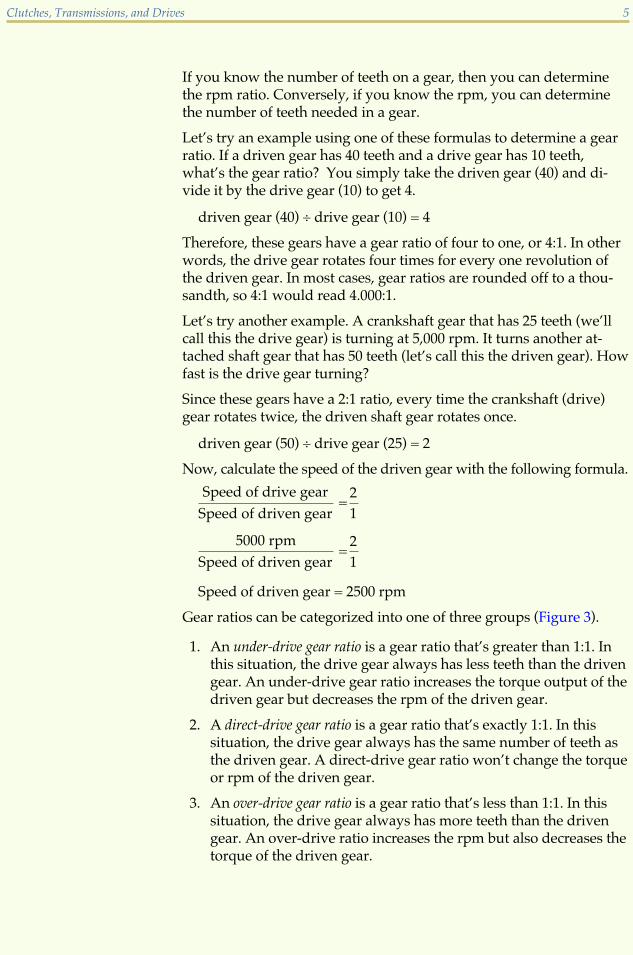
If you know the number of teeth on a gear, then you can determinethe rpm ratio. Conversely, if you know the rpm, you can determinethe number of teeth needed in a gear.
Let’s try an example using one of these formulas to determine a gearratio. If a driven gear has 40 teeth and a drive gear has 10 teeth,what’s the gear ratio? You simply take the driven gear (40) and di-vide it by the drive gear (10) to get 4.
driven gear (40) � drive gear (10) = 4
Therefore, these gears have a gear ratio of four to one, or 4:1. In otherwords, the drive gear rotates four times for every one revolution ofthe driven gear. In most cases, gear ratios are rounded off to a thou-sandth, so 4:1 would read 4.000:1.
Let’s try another example. A crankshaft gear that has 25 teeth (we’llcall this the drive gear) is turning at 5,000 rpm. It turns another at-tached shaft gear that has 50 teeth (let’s call this the driven gear). Howfast is the drive gear turning?
Since these gears have a 2:1 ratio, every time the crankshaft (drive)gear rotates twice, the driven shaft gear rotates once.
driven gear (50) � drive gear (25) = 2
Now, calculate the speed of the driven gear with the following formula.
Speed of drive gear
Speed of driven gear=
2
1
5000 rpm
Speed of driven gear=
2
1
Speed of driven gear = 2500 rpm
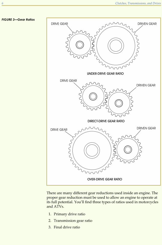
Gear ratios can be categorized into one of three groups (Figure 3).
1. An under-drive gear ratio is a gear ratio that’s greater than 1:1. Inthis situation, the drive gear always has less teeth than the drivengear. An under-drive gear ratio increases the torque output of thedriven gear but decreases the rpm of the driven gear.
2. A direct-drive gear ratio is a gear ratio that’s exactly 1:1. In thissituation, the drive gear always has the same number of teeth asthe driven gear. A direct-drive gear ratio won’t change the torqueor rpm of the driven gear.
3. An over-drive gear ratio is a gear ratio that’s less than 1:1. In thissituation, the drive gear always has more teeth than the drivengear. An over-drive ratio increases the rpm but also decreases thetorque of the driven gear.
Clutches, Transmissions, and Drives 5
There are many different gear reductions used inside an engine. Theproper gear reduction must be used to allow an engine to operate atits full potential. You’ll find three types of ratios used in motorcyclesand ATVs.
1. Primary drive ratio
2. Transmission gear ratio
3. Final drive ratio
6 Clutches, Transmissions, and Drives
FIGURE 3—Gear Ratios

Primary Drive RatioThe primary drive ratio is the gear reduction that’s determined fromthe crankshaft to the clutch of the engine. When computing the pri-mary drive ratio, the crankshaft output gear is considered to be thedrive gear. The clutch has a gear attached to it and is considered thedriven gear. For example, if a crankshaft gear has a tooth count of 41and the clutch-attached gear has a tooth count of 89, the primarydrive ratio is 89 (driven) divided by 41 (drive). The result (roundedoff to the thousandth) is 2.171:1.
Transmission Gear RatioThe transmission transmits power from the clutch, which is attachedto the main shaft (drive side) of the engine, to the countershaft (drivenside) of the engine. Transmission gear ratios are needed to allow for themany different power requirements needed. There may be as few astwo to as many as six different transmission gear ratios used in atransmission. For example, a main shaft gear with 22 teeth and acountershaft gear with 28 teeth have a gear ratio of 1.273:1. This is de-termined by dividing the driven countershaft gear teeth (28) by thedrive main shaft gear teeth (22) which results in a gear ratio of 1.273:1.
Final Drive RatioThe final drive ratio transmits the power output of the transmission tothe rear wheel. In this case, the transmission output shaft (in mostcases this will be the countershaft) has a sprocket attached to it whichdrives the rear wheel through a roller chain. An example of a finaldrive ratio is an output shaft sprocket size of 16 teeth and a rear wheelsprocket size of 46 teeth. In this case, you would divide 46 by 16. Theresult of the ratio (rounded off to the thousandth) is 2.875:1.
Overall Gear RatioThere’s one other ratio that directly relates to the ratios that we justcovered. This ratio is known as the overall gear ratio. This ratio com-pares the number of times the crankshaft turns to the turning of therear wheel. This ratio gives us the numerical gear ratio from thecrankshaft to the rear wheel. Generally this ratio is calculated with thetransmission in its highest gear, but it can be calculated for any gear.The formula to calculate the overall ratio is
Overall gear ratio = (primary) � (transmission) � (final drive) ratio
If we take the figures obtained in each of the examples above, wecan calculate the overall gear ratio (rounded off to the thousandth)as follows:
2.171 � 1.273 � 2.875 = 7.946:1
This tells us that for every one revolution of the rear wheel, the crank-shaft rotates 7.946 times.
Clutches, Transmissions, and Drives 7

As you can see, gears have a very important use in engines. Engineswith high horsepower can use a lower gear ratio. Engines with a lowhorsepower rating require a higher gear ratio to allow for the full useof the available horsepower. An engine with a higher overall gear ra-tio won’t have as much top speed capability but will reach its maxi-mum available speed quicker than an engine that has a lower overallgear ratio.
Road Test 1
At the end of each section of Clutches, Transmissions, and Drives, you’ll be asked to check yourunderstanding of what you've just read by completing a “Road Test.” Writing the answersto these questions will help you review what you've learned so far. Please complete Road Test 1now.
1. The _______ gear changes direction at 90°.
2. A gear ratio that has less teeth on its drive gear than it has on its driven gear is what typeof gear ratio?
3. The _______ gear is the most commonly used gear on motorcycles.
4. A gear that’s pie-shaped is known as a _______ gear.
5. A gear ratio that has the same number of teeth on its drive gear and its driven gear is whattype of gear ratio?
6. If a crankshaft drive gear has 22 teeth and the clutch outer basket has 68 teeth, the ratio forthis set of gears is _______.
7. A gear on a main shaft has 28 teeth and the countershaft has 33 teeth; the ratio for this setof gears is _______.
8. If the countershaft sprocket has 15 teeth and the rear wheel sprocket has 42 teeth, the ratiofor this set of gears is _______.
9. By using the ratios from questions 6, 7, and 8, the overall gear ratio for this motorcycle orATV is _______.
10. A gear ratio that has more teeth on its drive gear than it has on its driven gear is what typeof gear ratio?
Check your answers with those on page 49.
8 Clutches, Transmissions, and Drives

PRIMARY DRIVESAll engines require a gear reduction system that’s used to transfer thepower from the crankshaft to the transmission, and then from thetransmission to the rear wheel. The gear reduction system used fortransferring the power from the crankshaft to the clutch is called theprimary drive. As you’ve learned, gear reduction is necessary to allowthe engine to remain in the appropriate range of rpm while maintain-ing various speeds at the rear wheel. In other words, we need a gearreduction system so that the engine crankshaft can turn at one speedwhile the rear wheel turns at another speed. A clutch system is neededto engage and disengage the power from the crankshaft to the trans-mission. Before we learn about the different types of clutches, we’llfirst discuss the types of primary drive systems found in today’s mo-torcycle and ATV engines. A primary drive system transfers powerfrom the crankshaft to the clutch by using gears, a chain, or a belt(Figure 4). These are the three basic methods of connecting the engineto the clutch and transmission.
Gear-Driven Primary DriveMost motorcycles and ATVs use a gear-driven primary drive system.This system uses either spur, offset spur, or helical gears to transferpower from the crankshaft to the clutch system. With a gear-drivenprimary drive system, the two gears turn in opposite directions be-cause each gear is on a separate shaft. This makes the clutch turn inthe opposite direction of the crankshaft. You must lubricate gear-driven primary drive systems to prevent excessive heat caused by thefriction of the gears as they mesh together as the engine operates.
Clutches, Transmissions, and Drives 9
FIGURE 4—Primary Drives (Courtesy of American Suzuki Motor Corporation)
Chain-Driven Primary DriveThe chain-driven primary drive uses a chain and two gears or sprock-ets to transfer power from the crankshaft to the clutch system. Sprock-ets are the teeth on the periphery of a wheel or cylinder that engagethe links of a chain. With a chain-driven primary drive, both sprock-ets turn in the same direction and use either a roller chain or a Hy-Vochain design. The Hy-Vo chain design is the most commonly used asit’s a much stronger design and quieter than the roller chain. Youmust keep chain-driven primary drive systems well lubricated.
Belt-Driven Primary DriveThe belt-driven primary drive system uses a toothed belt called a“Gilmer-type belt” and two pulleys with teeth attached to them. Justlike the chain-driven primary drive system, the belt-driven type hasboth pulleys turning in the same direction. This type of primary driveis very quiet because it uses a belt instead of gears or a chain. Unlikethe other primary drive systems, you must keep a belt-driven pri-mary drive dry.
CLUTCH SYSTEMSNow that we have a gear reduction system in place for the power atthe crankshaft, there must be a way to interrupt that power flow whenwe need to stop the motorcycle or ATV. We also need a way to permita gradual engagement of the motorcycle or ATV when you decide tohave the machine move again. This power interruption is done usinga clutch. As we mentioned earlier, the purpose of the clutch is todisconnect and connect the power of the crankshaft. The clutch is nor-mally placed between the primary drive of the engine and the trans-mission. Clutch actuation can be divided into two different types: (1)manual clutch actuation, which is controlled by the rider and (2) cen-trifugal clutch actuation, which is controlled by the engine’s rpm.There are three basic clutch designs used in engines:
1. Manual clutch
2. Centrifugal (also referred to as automatic) clutch
3. Variable-ratio clutch
We’ll discuss these clutch designs next.
Manual ClutchA manual clutch allows the rider to control the engagement and dis-engagement of the power flow from the crankshaft to the transmis-sion. The manual clutch is the most conventional type of clutch used
10 Clutches, Transmissions, and Drives

on motorcycles and ATVs. A manual clutch may be wet or dry. Bothwet and dry clutches are extremely similar in design and function.The main difference between wet and dry clutches is the way they’recooled. A wet clutch operates in an oil bath to keep its componentscool. The oil carries the heat generated by the clutch away from theclutch to help keep it cool. A dry clutch uses airflow to keep the clutchcool. There are two styles of manual clutches used: single-plate andmultiplate. A single-plate clutch, which is very similar to the clutchsystem used for automobiles, is usually found in conjunction with adry clutch. A multiplate clutch is the most conventional style of clutchfound on motorcycles and ATVs. All manual clutches consist of thesame basic components. We’ll concentrate primarily on the multiplatemanual wet clutch because dry clutches aren’t as popular on motorcy-cles and ATVs.
Multiplate Manual ClutchA multiplate clutch has as few as two plates and up to as many astwenty plates. By using more plates, the clutch can be made smallerin diameter while keeping the same amount (or more) of friction ma-terial for engagement purposes. Although terminology varies, allmultiplate clutches have the same basic components (Figure 5).
� The clutch outer, which may also be called the clutch basket, con-tains all of the components of the clutch and has the driven gearfor the primary drive attached to it. This component freewheelson the transmission main shaft and rotates whenever the engineis running. Most clutch outers use springs or rubber dampers toabsorb excess power pulses so that the pulses aren’t transmitted
Clutches, Transmissions, and Drives 11
FIGURE 5—MultiplateManual Clutch with InnerPressure Plate (Copyright by
American Honda Motor Co., Inc. and
reprinted with permission)

through the rest of the drive line. The clutch outer is driven bythe engine and is tabbed (connected) to all of the clutch plates.
� The clutch center, which may also be called the inner clutch hub,is splined to the transmission main shaft and secured with alocknut. The clutch center has splines machined into it and isdriven by the clutch plates. When the clutch plates rotate, theclutch center also rotates. The clutch center is connected directlyto the transmission. The clutch center is tabbed to all of theclutch discs.
� Clutch discs transmit the power of the clutch outer to the clutchcenter and are normally made of a high-friction material. Clutchdiscs are also known as friction plates. The materials used tomake friction plates are well-kept secrets by the makers of dif-ferent clutches, but it’s known that some of the materials usedto produce friction discs are cork, neoprene, and Kevlar. Thesediscs are connected to and driven by the clutch outer. Clutch discshave tabs on their outer edge that fit into the slots, or fingers,in the clutch outer. Like the clutch outer, the clutch discs rotatewhenever the engine rotates. This being a wet clutch, the frictionmaterial is kept cool by the oil in the lubrication system. As theclutch friction material wears down, it begins to contaminate theoil in the transmission.
� Clutch plates are connected to and used to transfer the powerfrom the clutch discs to the clutch center. When the clutch platesrotate, the transmission shaft also rotates.
� The clutch pressure plate applies pressure to the clutch platesand discs, which prevents the clutch from slipping. Whenpressed together, the clutch plates and discs form one unit andallow power to flow through them. The clutch pressure plate ispushed by the clutch release mechanism, which releases thepressure applied to the plates and discs to separate them fromeach other and to disengage the clutch.
� Clutch springs hold the clutch pressure plate firmly against theclutch plates and discs.
� The lifter rod applies pressure to the clutch pressure plate torelease the clutch.
� The bearing reduces the friction of the lifter rod as it appliespressure to the clutch pressure plate.
� The push rod pushes the lifter rod, which in turn releases theclutch pressure plate. Push rods may be installed through themain shaft as illustrated in Figure 5 or they may be attached tothe outside of the clutch.
12 Clutches, Transmissions, and Drives

Single-Plate Manual ClutchThe single-plate manual clutch uses the same basic components as themultiplate clutch. As the name implies, the main difference betweenthe two clutches is that the single-plate manual clutch uses only a sin-gle friction plate. This type of clutch is used on BMW motorcycles.
Manual Clutch Release MechanismsClutch release mechanisms are used to disengage the power flow fromthe engine to the transmission. Clutches are designed to have an innerpressure plate or an outer pressure plate (Figure 6).
Clutches, Transmissions, and Drives 13
FIGURE 6—MultiplateManual Clutch with Inneror Outer Pressure Plate(Copyright by American Honda Motor
Co., Inc. and reprinted with permission)

When the clutch is disengaged, the release mechanism pushes againstthe clutch pressure plate. This pressure separates the clutch driveplates from the driven plates. The clutch must be engaged graduallyto prevent a sudden grabbing of the clutch which will cause the mo-torcycle or ATV to lurch forward. There are seven common manualclutch release mechanisms:
� Rocker arm
� Ball and ramp
� Rack and pinion
� Lever
� Cam
� Screw
� Hydraulic
All but the hydraulic release mechanism use a cable that’s attached tothe handle bar to activate them. The hydraulic method uses hydraulicfluid in place of the cable.
Multiplate Manual Clutch OperationA clutch is either engaged or disengaged (Figure 7). The followingparagraphs describe each of these conditions.
14 Clutches, Transmissions, and Drives
FIGURE 7—ClutchOperation (Copyright by Ameri-
can Honda Motor Co., Inc. and re-
printed with permission)

Engaged. When the transmission is shifted into gear and the clutchlever is gradually released, the clutch discs and clutch plates becomecaught between the pressure plate and the clutch center. This nowprevents the clutch from slipping and the power of the crankshaft iscompletely transmitted to the rear wheel.
Disengaged. When the clutch lever is pulled, the clutch push rodpushes against the clutch lifter rod. The clutch lifter rod applies pres-sure to the clutch pressure plate, resulting in a gap between the clutchdiscs and clutch plates. This separates the power of the crankshaftfrom the rear wheel and allows the clutch to slip.
Centrifugal ClutchThe centrifugal clutch (Figure 8) is among the simplest clutch designsand uses the engine’s rpm to engage and disengage the crankshaftpower to and from the engine’s final drive. Since this clutch systemrelies on the engine for engagement, there’s no need for a handlebar-mounted clutch lever. The centrifugal clutch uses weights and springsto determine the rpm’s necessary to disengage and engage the clutch.When the engine rpm’s are high enough to overcome the tension ofthe springs, centrifugal force throws the weights outward against theclutch drum to engage the crankshaft with the clutch outer. In manyATVs, this type of clutch is often used in conjunction with a manualmultiplate clutch, as shown in Figure 9. The combination of thesetwo clutch systems allows the engine to remain in gear while idling toallow the rider to come to a complete stop without having the enginestall.
Variable-Ratio ClutchVariable-ratio clutch systems (Figure 10) are often seen on motor-scooters and also may be found on some ATVs. Although named a“variable-ratio clutch,” this system is actually a transmission systemthat provides a variable drive ratio between the engine and the rearwheel. Power is never actually disengaged as it would be in a trueclutch. The variable-clutch system consists of a drive pulley which isattached to the engine crankshaft and a driven pulley that’s attachedto a shaft which may also incorporate a centrifugal clutch. The twopulleys are connected by a drive belt. Many variable-ratio clutch sys-tems also have a final gear reduction between the driven pulley andthe rear wheel to provide an extra increase in torque when needed.
Clutches, Transmissions, and Drives 15

16 Clutches, Transmissions, and Drives
FIGURE 8—A CentrifugalClutch (Copyright by American
Honda Motor Co., Inc. and reprinted
with permission)
FIGURE 9—Multiplate and Centrifugal Clutch (Copyright by American Honda Motor Co., Inc. and reprinted with permission)

Variable-Clutch Drive Pulley OperationThe drive pulley consists of a fixed and a movable face. The movableface has the capability to slide towards the drive face. There’s also aramp plate incorporated in the drive pulley which pushes weight roll-ers against the drive face. As engine speed increases, centrifugal forcepushes the weight rollers outward. This force pushes the movable facetoward the fixed face, which in turn pushes the drive belt upwardtoward the top of the drive pulley. This reduces the drive ratio by
Clutches, Transmissions, and Drives 17
FIGURE 10—Variable-Clutch Operation (Copyright by American Honda Motor Co., Inc. and reprinted with permission)

forcing the drive belt to ride on a pulley of larger diameter. As theengine speed decreases, the belt is pulled back into the drive pulley,which increases the drive ratio by allowing the belt to ride on a pulleyof smaller diameter.
Variable-Clutch Driven Pulley OperationBecause the belt remains constant in length, the driven pulley reactsto the drive pulley by allowing the drive belt to be pulled in towardthe center of the driven face. By doing this, the diameter of the belt onthe driven face decreases at higher engine speeds. When the enginespeed decreases and the belt is pulled back into the drive pulley, thedriven face spring moves the movable driven face towards its restingand original position. This pushes the drive belt back to the circum-ference of the driven pulley.
In the operations described above, the reduction ratio automaticallyvaries as the engine speed changes without the need to manually shiftto change gear ratios. When the engine is running at lower enginespeeds the gear ratio is high, which allows for greater torque. As en-gine speed increases, the drive ratio becomes lower between thedriven and drive pulleys.
Sprag ClutchAnother type of clutch used in different areas of the motorcycle is thesprag or “one-way” clutch (Figure 11). This type of clutch is used withsome primary drive systems as well as some electric starting systemsand prevents damage to the starter motor when the engine engages.The sprag clutch allows a portion of the clutch to slip when underhigh-stress situations such as rapid downshifting, when used in con-junction with the primary drive, or when trying to use the electricstarter and the engine backfires. This prevents the loss of traction thatcan occur as a result of extreme compression-braking forces withinthe engine. By allowing the clutch to slip, the rear wheel has bettertraction and won’t “hop” during compression-braking forces. Onmotorcycles and ATVs that have a centrifugal clutch system, a spragclutch may be used to provide some engine braking when the centrifu-gal clutch is disengaged. This gives the rider better control whenbringing the machine to a stop or going down hills.
18 Clutches, Transmissions, and Drives

Road Test 2
1. What are the names of the three types of primary drive systems that may be found onmotorcycles and ATVs?
2. What component is used to engage and disengage the power flow from the engine to thetransmission?
3. The _______ clutch is the most widely used clutch on motorcycles and ATVs.
4. The _______ clutch is used mostly on motorscooters and also on some ATVs.
5. When the _______ primary drive system is used, the crankshaft rotates in the oppositedirection as the clutch.
(Continued)
Clutches, Transmissions, and Drives 19
FIGURE 11—A Sprag Clutch (Copyright by American Honda Motor Co., Inc. and reprinted with permission)
Road Test 2
6. What clutch release mechanism doesn’t use a cable to actuate it?
7. The _______ clutch is both a clutch and a transmission.
8. Which type of clutch is often used in conjunction with a manual multiplate clutch inmany ATVs?
9. What component of a manual clutch is normally made of a high-friction material?
Check your answers with those on page 49.
SERVICE AND REPAIR OF CLUTCHESServicing and repairing clutch components are two of the jobs you’llneed to perform frequently as a technician. Because clutches are en-gaged and disengaged each time the transmission gears are shifted,clutch components have a tendency to wear. Additionally, the clutchparts perform the difficult job of locking the power output of theengine to the transmission and then to the drive wheel.
We can’t overemphasize the importance of correctly servicing clutchcomponents. Proper adjustment of the release lever, cable, release rod,spring pressure, and so forth determines how long a clutch performssatisfactorily. Because you can’t properly adjust parts which needrepairing, this section of your study unit is divided into two sections.The first section covers how to correctly adjust the various parts of theclutch assembly. The second section covers the repair of clutch parts.
Common Clutch ProblemsYou’ll find two common clutch problems with any of the previouslymentioned clutches in this study unit. The first problem is a clutchthat slips. Clutch slippage occurs when the clutch doesn’t have theability to transfer all of the engine’s power flow. This problem may becaused by improper adjustment, weak clutch springs, or worn clutchplates.
20 Clutches, Transmissions, and Drives

The second common problem you may find with a clutch is known asclutch drag. Clutch drag occurs when the clutch is unable to fully dis-engage. Clutch drag is evident when the engine power can’t be disen-gaged from the rear wheel. An example of this condition is when yousqueeze the clutch lever and the motorcycle or ATV still tries to moveforward. Possible causes of this condition include warped or bindingclutch plates, a worn clutch outer or clutch center, improper clutchadjustment, or a worn release mechanism.
Clutch AdjustmentMost clutch problems originate from an improperly adjusted clutch.Whenever there’s an indication of a clutch problem, it’s very impor-tant to verify that the clutch is adjusted properly. In most cases, a sim-ple adjustment solves either a slipping or a dragging clutch. Mostmanual clutches use a clutch cable to link the handlebar lever to theclutch release mechanism which is attached to the engine. Most mo-torcycles and ATVs that have a clutch cable also have a clutch cablelength adjuster and a clutch release adjuster—both of which you canuse to properly adjust the clutch.
The cable length adjuster is used to adjust the play in the cable. Themanufacturer has the correct specification for the lever in the servicemanual or the owner’s manual. You can adjust the amount of play inthe cable simply by turning the adjuster in or out.
The clutch release adjuster is used to verify that there’s a properamount of clutch rod movement for correct disengagement. Onceproperly adjusted, you shouldn’t need to further adjust the releaseadjuster. Because there are many different types of adjusters and eachhas a specific method of adjustment, you’ll need to refer to the manu-facturer’s service manual for the correct procedure. For any adjust-ments thereafter, you’ll need to remove excess slack from the clutchcable as it stretches.
The next portion of this study unit concentrates on the service and re-pair of wet multiplate manual clutches primarily because they’re themost popular clutch used. Before proceeding, we suggest that you re-view our discussion on the manual multiplate clutch system compo-nents so that you’ll have a picture in your mind of how a clutchworks as you continue with this lesson on clutch repair. In that sec-tion of the study unit, you learned about the various internal clutchparts and how they work. In this lesson, we’ll be working with the en-tire clutch assembly, including parts such as the clutch handlebarlever and clutch cable.
Clutches, Transmissions, and Drives 21

Multiplate Manual Clutch AdjustmentThe proper sequence for clutch adjustment is
1. Adjust the release mechanism at the engine.
2. Adjust the cable play at the clutch lever.
As discussed before, clutches that drag (don’t fully disengage) pre-vent smooth shifting of transmission gears; clutches that slip (don’tfully engage) won’t transmit all available engine power to the trans-mission. Sometimes either one of these conditions can be corrected bymaking simple clutch adjustments.
These problems may be caused by
� Not enough cable movement at the handlebar lever
� Improper cable adjustment
� Improper release rod adjustment
� Improper spring tension
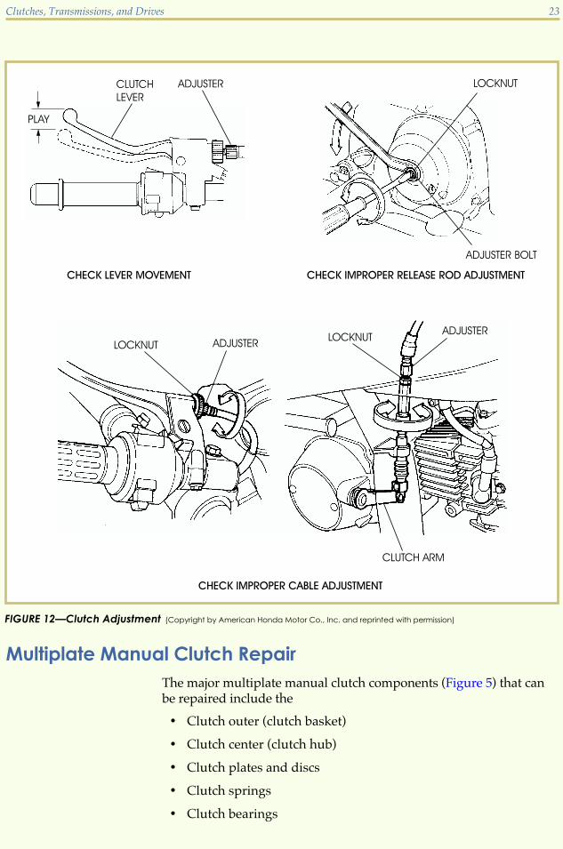
These problems may be interrelated. The following items must bechecked to ensure correct adjustment of each part (Figure 12).
Lever Movement. You should be sure that the clutch lever on the han-dlebar isn’t bent and has as much movement as it was designed tohave. You should also be sure that the lever doesn’t contact the han-dlebar grip before the inner clutch cable has been pulled to its maxi-mum extension.
Improper Cable Adjustment. You must adjust the cable so that it has1
16 inch to 316 inch play, that is, so that the lever on the handlebar can
be depressed 116 inch to 3
16 inch before the pressure of the clutch springresisting release can be felt. Take the measurement from where thecable attaches to the handlebar lever. Adjust the cables by turning theadjuster at either end of the cable. Turn the adjuster “in” for moreplay and “out” for less play. If the play is measured out at the end ofthe clutch lever, the measurement should be from 1� to1 1
4�.
Improper Release Rod Adjustment. The release rod adjustment mustallow enough play in the release rod to allow the springs to expand,but not too much play or the rod won’t move far enough to relievethe pressure from the clutch plates. To adjust the release rod, youmust first disconnect the clutch cable from the release rod lever lo-cated on the engine cover case. Next, you must adjust the release rodscrew so that pressure is applied against the springs. Then you mustreadjust the adjustment screw to allow for the manufacturer’s recom-mended play of the release rod lever. You should be able to move theend of the release rod lever 1
32 to 116 inch from fully open before the
clutch spring pressure resists the lever movement.
22 Clutches, Transmissions, and Drives
Multiplate Manual Clutch RepairThe major multiplate manual clutch components (Figure 5) that canbe repaired include the
� Clutch outer (clutch basket)
� Clutch center (clutch hub)
� Clutch plates and discs
� Clutch springs
� Clutch bearings
Clutches, Transmissions, and Drives 23
FIGURE 12—Clutch Adjustment (Copyright by American Honda Motor Co., Inc. and reprinted with permission)
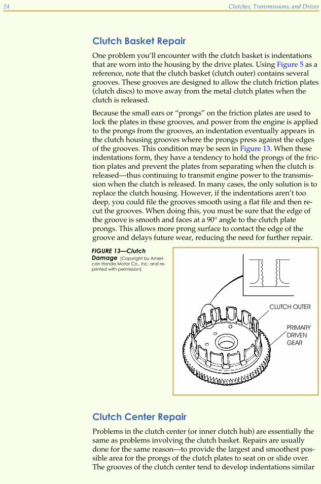
Clutch Basket RepairOne problem you’ll encounter with the clutch basket is indentationsthat are worn into the housing by the drive plates. Using Figure 5 as areference, note that the clutch basket (clutch outer) contains severalgrooves. These grooves are designed to allow the clutch friction plates(clutch discs) to move away from the metal clutch plates when theclutch is released.
Because the small ears or “prongs” on the friction plates are used tolock the plates in these grooves, and power from the engine is appliedto the prongs from the grooves, an indentation eventually appears inthe clutch housing grooves where the prongs press against the edgesof the grooves. This condition may be seen in Figure 13. When theseindentations form, they have a tendency to hold the prongs of the fric-tion plates and prevent the plates from separating when the clutch isreleased—thus continuing to transmit engine power to the transmis-sion when the clutch is released. In many cases, the only solution is toreplace the clutch housing. However, if the indentations aren’t toodeep, you could file the grooves smooth using a flat file and then re-cut the grooves. When doing this, you must be sure that the edge ofthe groove is smooth and faces at a 90° angle to the clutch plateprongs. This allows more prong surface to contact the edge of thegroove and delays future wear, reducing the need for further repair.
Clutch Center RepairProblems in the clutch center (or inner clutch hub) are essentially thesame as problems involving the clutch basket. Repairs are usuallydone for the same reason—to provide the largest and smoothest pos-sible area for the prongs of the clutch plates to seat on or slide over.The grooves of the clutch center tend to develop indentations similar
24 Clutches, Transmissions, and Drives
FIGURE 13—ClutchDamage (Copyright by Ameri-
can Honda Motor Co., Inc. and re-
printed with permission)
to those that develop on the grooves of the clutch housing. As withthe clutch basket, if these indentations aren’t too deep, the groovescan be filed smooth with a file.
Clutch Plates and Disc RepairRepairs to clutch plates and discs depend a great deal on the motorcy-cle model you’re repairing. Generally, clutch plates and discs needreplacement when they don’t perform satisfactorily or don’t meet fac-tory specifications. As a general rule, clutch plates are replaced whenthey’re warped beyond the manufacturer’s specifications; clutch discsare replaced when they’re worn beyond their service limit thickness.
Clutch Spring RepairClutch springs must apply equal pressure to both the drive anddriven clutch plates. These springs aren’t normally adjustable, butwhen worn will apply unequal pressure to the clutch plates, whichmay cause the clutch to slip. This spring tension problem is correctedby replacing the clutch springs. After replacing springs, you shouldperform a final adjustment of the clutch push rod to be certain it hasthe proper amount of play.
Clutch Bearing RepairYou should recall that the function of the clutch bearing is to reducethe friction between the clutch lifter rod and the clutch pressure platewhen the clutch is disengaged and engine power isn’t being transmit-ted to the transmission. Clutch bearings may be of the ball bearing,roller bearing, or bushing type. Each type of bearing eventually becomesworn and needs replacing. In many cases, to replace the bearing, you’llhave to completely disassemble the clutch components because thebearing is in the centermost part of the clutch. This is discussed ingreater detail later in this study unit.
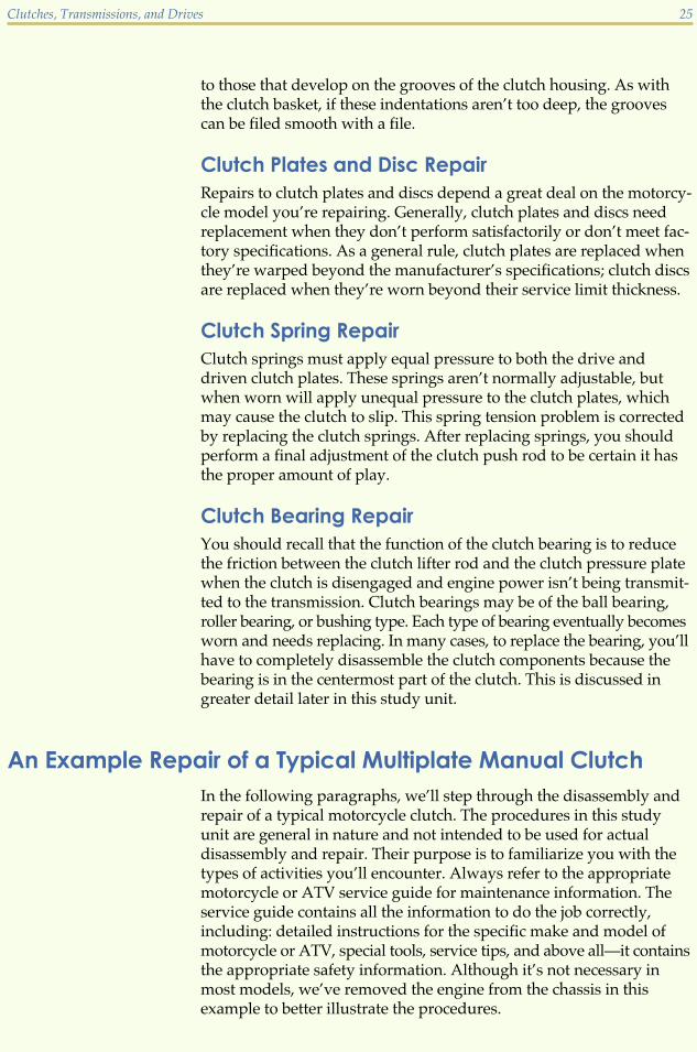
An Example Repair of a Typical Multiplate Manual ClutchIn the following paragraphs, we’ll step through the disassembly andrepair of a typical motorcycle clutch. The procedures in this studyunit are general in nature and not intended to be used for actualdisassembly and repair. Their purpose is to familiarize you with thetypes of activities you’ll encounter. Always refer to the appropriatemotorcycle or ATV service guide for maintenance information. Theservice guide contains all the information to do the job correctly,including: detailed instructions for the specific make and model ofmotorcycle or ATV, special tools, service tips, and above all—it containsthe appropriate safety information. Although it’s not necessary inmost models, we’ve removed the engine from the chassis in thisexample to better illustrate the procedures.
Clutches, Transmissions, and Drives 25

1 Drain the oil from the transmission and clutchcover case.
2 Remove the screws securing the clutch cover caseand lift off the cover case.
3 Remove the screws securing the clutch springs.Compare the length of the old springs with thelength of a new spring. Replace the old springs ifthey’re shorter.
Note: Most service manuals have specifications forcorrect spring length which are measured using avernier caliper.
4 Lift the pressure plate.
Note: Some models have the springs located insidethe pressure plate, and on these models steps 3 and4 would be reversed.
5 Pull the lifter rod from the hollow transmissioninput shaft.
26 Clutches, Transmissions, and Drives

Note: Not all clutches use the same method of at-taching the lifter rod. This illustration shows an ex-ample of another type of release rod mechanism.The release rod bearing is in the mechanic's handin this illustration. The bearing fits into the hole inthe center of the clutch and presses against thespring retainer when the clutch is disengaged.
6 Remove each of the friction discs and clutch platesand inspect them for wear.
7 Measure the clutch friction plates to be sure they’rethe correct thickness.
Note: When clutch friction plates become wornthey can become too thin, causing the clutch toslip. The service manual for your particular modelof motorcycle will tell you how thick the clutchplates should be. The most popular choice formeasuring the thickness of the clutch friction andsteel plates is the vernier caliper. Each plate mustbe measured individually.
8 Check the clutch plates for warpage by puttingeach plate on a flat surface and running a feelergauge under the edge. If the feeler gauge slips inanywhere under the edge, the plate is warped andmust be replaced.
9 Inspect the clutch basket and clutch center grooves.Be sure the grooves are smooth so that the prongs ofboth the driving and driven plates fit properly.
Note: You can make a clutch center holding tool bywelding a steel rod to an old clutch plate.
10 Place the plate over the clutch center to keep itfrom turning. Remove the nut securing the clutchcenter. Remove the clutch center and housing.
Clutches, Transmissions, and Drives 27

Note: Some motorcycles and ATV engines securethe clutch to the transmission input shaft with aretaining ring.
11 Remove the clutch using retaining-ring pliers orother appropriate tool.
12 Inspect the clutch basket bearing or bushing forexcessive wear. If the clutch housing has excessivewobble when placed on the shaft, replace thebearing.
13 Reassemble the unit by placing the bearing (orbushing), spacers, housing, and clutch center onthe transmission main shaft. Secure with the nutand bend the lock washer against the flat part ofthe nut, or replace the retaining ring.
Note: On some models which use a retaining ringto secure the clutch to the shaft, you may need toinstall the clutch plates before installing the retain-ing ring.
28 Clutches, Transmissions, and Drives
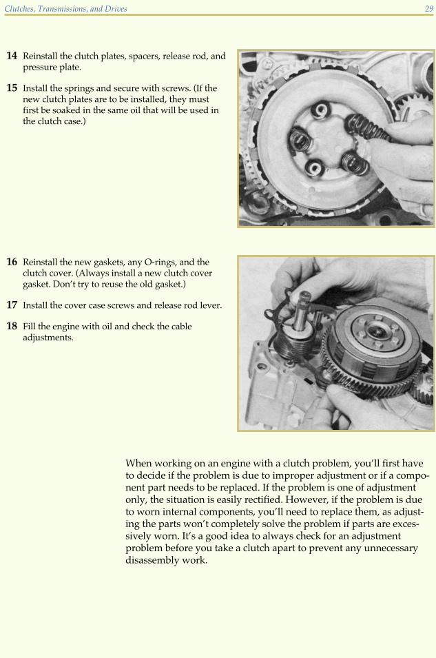
14 Reinstall the clutch plates, spacers, release rod, andpressure plate.
15 Install the springs and secure with screws. (If thenew clutch plates are to be installed, they mustfirst be soaked in the same oil that will be used inthe clutch case.)
16 Reinstall the new gaskets, any O-rings, and theclutch cover. (Always install a new clutch covergasket. Don’t try to reuse the old gasket.)
17 Install the cover case screws and release rod lever.
18 Fill the engine with oil and check the cableadjustments.
When working on an engine with a clutch problem, you’ll first haveto decide if the problem is due to improper adjustment or if a compo-nent part needs to be replaced. If the problem is one of adjustmentonly, the situation is easily rectified. However, if the problem is dueto worn internal components, you’ll need to replace them, as adjust-ing the parts won’t completely solve the problem if parts are exces-sively worn. It’s a good idea to always check for an adjustmentproblem before you take a clutch apart to prevent any unnecessarydisassembly work.
Clutches, Transmissions, and Drives 29

Road Test 3
1. True or False? A clutch that won’t fully disengage can be the cause of a motorcycle or ATVthat has a tendency to creep even though the clutch lever is fully depressed.
2. True or False? Worn-out clutch springs can cause a clutch to slip.
3. What is the proper sequence for correct clutch adjustment?
4. The two most common problems found in clutches are _______ and _______.
5. The proper measuring tool to check for the thickness of the clutch friction plates is a_______.
6. True or False? A grooved clutch basket can be repaired by filing it smooth.
7. Clutch plates need to be replaced when they become _______ beyond factory specifications.
8. What must be done before removing the clutch cover to prevent oil from spilling?
Check your answers with those on page 49.
TRANSMISSIONSNow that you understand how and why primary drive systems andclutches are used on motorcycles and ATVs, we can move on to ourdiscussion about engine transmissions. All motorcycles and ATVs re-quire a method of transmitting the power from the engine to the rearwheel. Transmissions are used to change the speed of the machinewhile keeping the engine within its usable power band. A transmis-sion consists of shafts and gears which are arranged to provide differ-ent gear ratios to the rear wheel. Transmissions allow the rider toincrease and decrease the wheel speed while maintaining a constantengine speed.
Transmission types vary from one manufacturer to another. How-ever, if you can understand the basic principles of how the mostpopular transmissions operate, you’ll be on your way to becoming afirst-class motorcycle and ATV technician. In this lesson we’re goingto help you get a thorough understanding of how transmissionswork.
30 Clutches, Transmissions, and Drives

In its simplest form, a transmission consists of a centrifugal clutch-attached to the crankshaft (input shaft). A belt or chain will be con-nected between the clutch and the rear wheel via a pulley or belt. Asthe engine speed increases, the clutch activates and propels the rearwheel. This type of transmission is an example of a single-speedtransmission, which isn’t the most efficient system available.
Transmission GearsMost transmissions contain a combination of gears. The gears thatmay be found in a transmission include fixed gears, freewheelinggears, and sliding gears (Figure 14).
Fixed GearsA fixed gear is one that doesn’t move on the shaft to which it’s at-tached. Fixed gears are attached to a shaft in one of three ways. Thegear may be machined as part of the shaft, splined to the shaft, orpressed onto the shaft. A fixed gear rotates at shaft speed.
Clutches, Transmissions, and Drives 31
FIGURE 14—TransmissionGears (Courtesy of American Suzuki
Motor Corporation)

Freewheeling GearsA freewheeling gear moves freely on its shaft and is usually held inplace by retaining rings. A freewheeling gear doesn’t have to rotate atshaft speed and has slots or protrusions (called dogs) on its sideswhich allow the gear to engage a sliding gear. For a constant-meshtransmission to operate correctly, there must be a freewheeling gearopposed to a fixed or sliding gear on the opposite shaft. Constant-mesh transmissions are discussed a little later in this study unit.
Sliding GearsA sliding gear is one that can slide across the axis of the shaft. A slid-ing gear is splined to the shaft and rotates at shaft speed. The purposeof this type of gear is to engage and disengage transmission gears.Sliding gears are moved left or right across the axis of the shaft bya shift fork (Figure 15). A sliding gear has dogs on its sides that aredesigned to engage a freewheeling gear.
Constant-Mesh TransmissionsThe most common transmission design is the constant-mesh trans-mission design (Figure 16). With a constant-mesh transmission, theteeth of all gears mesh with their mate on the opposing shaft at alltimes. The most common gears used in a typical constant-mesh trans-mission are spur (straight-cut) gears. There are two types of constant-mesh transmissions—indirect drive and direct drive.
32 Clutches, Transmissions, and Drives
FIGURE 15—A shift forkmust be straight to fitbetween the gears.

Indirect-Drive TransmissionsIndirect-drive transmissions have power entering on one shaft andexiting from another shaft on a different axis (Figure 17). The main, ordrive, shaft of an indirect-drive transmission is splined to the clutchcenter. Power is transmitted through the clutch to the main shaft. Themain shaft rotates opposite the countershaft. Power flow generally ex-its on the countershaft. The transmission countershaft turns the coun-tershaft sprocket which is connected to the rear wheel.
The following facts apply to indirect-drive transmissions.
� All gears on the main shaft are drive gears.
� The smallest gear on the main shaft is a fixed gear and is part oflow gear. The largest gear on the main shaft is part of high gear.
Clutches, Transmissions, and Drives 33
FIGURE 16—A Typical DriveShaft with a Constant-MeshIndirect-Drive Transmission

� All gears on the countershaft are driven gears.
� The largest gear on the countershaft is part of first gear. Thesmallest gear on the countershaft is part of high gear.
Direct-Drive TransmissionsWith a direct-drive transmission, the power flow enters on one shaftand leaves on another shaft of the same axis, instead of a differentaxis as found with the indirect-drive transmission. Top or high gearwith the direct-drive transmission always has a ratio of 1:1, hence thename, “direct-drive.” This type of transmission was widely used onolder European motorcycles as with many older American-made mo-torcycles. The direct-drive transmission is often housed in a separategearbox which isn’t a part of the actual engine. Currently, the direct-drive transmission is found only on certain American-made motorcy-cles of the V-twin variety (Harley Davidson). There’s a study unit thatcovers this type of motorcycle specifically, and we’ll further study thedirect-drive type of transmission in that study unit.
34 Clutches, Transmissions, and Drives
FIGURE 17—Indirect-DriveTransmission (Courtesy Kawasaki
Motor Corp., U.S.A.)

Dual-Range TransmissionsAnother type of transmission, the dual-range transmission (alsoknown as a subtransmission), is found in some dual-purpose motorcy-cles and widely found on ATVs. This type of transmission is a two-speed (high and low), auxiliary transmission that’s placed into thepower flow between the transmission output side and the final drivesystem. Usually, a dual-range transmission has a manual shiftingarrangement. The dual range allows a trail bike to be on-road oroff-road, and a touring motorcycle to have fast acceleration for citydriving (low range) as well as a high range for long trips.
Shifting Transmission GearsWhen you move the gearshift lever on a constant-mesh transmission,you’re also moving mechanical connections which are linked to cer-tain gears within the transmission. Each movement of the shift leverlocks one set of gears into position, and this set of gears is then en-gaged. At the same time, all other gears within the transmission aredisengaged. Thus, shifting gears is the way you control the position ofgears in the transmission and select different gear ratios that best suitthe riding conditions. There are several different components thatmake up the gear-shifting mechanism used on motorcycle and ATVtransmissions. Later in this study unit, we’ll look at some of themmore closely.
The shifting sequence for a transmission is
1. Your foot moves the shift lever which is attached to a shift link-age.
2. The shift linkage moves a shifting mechanism.
3. The shifting mechanism moves a shift fork which in turn moves asliding gear to engage and disengage the transmission gear.
Let’s trace the power flow through a typical four-speed indirect-drivetransmission. Although the gear arrangement and number of gearsvary greatly in engines used for motorcycles and ATVs, the powerflow of indirect-drive transmissions is similar to that of the followingexample.
Indirect-Drive Transmission Power Flow
NeutralLet’s begin with the gear selection where there’s no power transmittedto the rear wheel—neutral. Using Figure 18 as a reference, let’s findout why power can’t be delivered when the gears are in this position.
Clutches, Transmissions, and Drives 35

� Gear #1 is a fixed gear and turns with the main shaft. It mesheswith gear #5 on the countershaft, causing it to spin. Becausegear #5 is a freewheeling gear, no power is transmitted to thecountershaft.
� Gear #2 is also a freewheeling gear, so power can’t be transmittedto sliding gear #6 when the main shaft rotates.
� Gear #3 is a sliding gear and turns with the main shaft. It mesheswith freewheeling gear #7, so power can’t be transmitted in thisposition.
� Gear #4 is a freewheeling gear and can’t transmit power to fixedgear #8 when arranged in this neutral position.
If you could see inside the transmission with the engine running andthe gears in this neutral position, you would see the main shaft andgears #1 and #3 turning gears #5 and #7 with no rotation of the counter-shaft.
First GearComparing Figure 18 (neutral gear) with Figure 19, you’ll notice thatgear #6, a sliding gear, has moved to the right. This gear change fromneutral to first gear connects freewheeling gear #5 with sliding gear# 6, which is splined to the countershaft. By following the arrow, youcan trace the power flow from the main shaft and gear #1 to gear #5and #6, and through the countershaft which is now rotating to trans-mit power in first or “low” gear ratio.
36 Clutches, Transmissions, and Drives
FIGURE 18—Neutral Gear

Second GearShifting from first gear into second gear causes two major changes inthe arrangement of the gears. When comparing Figure 19 to Figure 20you’ll notice that sliding gear #6 has moved to the left, out of engage-ment with gear #5. Also, sliding gear #3 has moved to the right, intoengagement with freewheeling gear #2. You can trace the power flow
and gear #2 to gear #6 (a sliding gear), which transmits power androtation to the countershaft.
Third GearIn Figure 21, notice that in shifting from second gear to third gear,sliding gear #3 has moved to the left, out of engagement with gear#2, and now meshes with gear #7. Also notice that sliding gear #6has moved to the left to lock freewheeling gear #7 to the countershaft.As the arrow indicates, power flows through the main shaft andgear #3 (splined) into gear #7 and through the countershaft.
Clutches, Transmissions, and Drives 37
FIGURE 19—First Gear
FIGURE 20—SecondGear
in the figure by following the solid line arrow from the main shaft

Fourth GearIn a four-speed transmission, fourth gear is also called top gear or high
gear #6 has shifted to the right, out of engagement with gear #7. Alsonotice that sliding gear #3 has moved to the left to connect with free-wheeling gear #4. As the arrow indicates, power now flows throughthe main shaft and gears #3 and #4 into gear #8 (a fixed gear) and outthrough the countershaft to the final drive system. Final drive systemsare covered later in this study unit.
Shifting MechanismsManufacturers of motorcycles and ATVs use many different mechani-cal systems to change the internal transmission gears from one gearratio to another. Let’s look at how the most common shifting mecha-nisms work. Once you gain an understanding of these mechanisms,learning how the variations operate is easy.
38 Clutches, Transmissions, and Drives
FIGURE 21—Third Gear
FIGURE 22—Fourth Gear
gear. In Figure 22, notice that in shifting from third gear to fourth gear,

The most common shifting mechanism in a constant-mesh transmis-sion uses a component called a shift drum along with shift forks (Fig-ure 23). You’ll recall that shift forks fit into the grooves of slidinggears and allow movement to the right or left on the transmissionshaft. Now let’s learn what makes them move.
Figure 24 shows an entire shifting-mechanism assembly. When therider’s foot moves the change pedal (shift lever) downward, gearshiftarms A and B move forward. The prongs on the end of gearshift armB pull on the gearshift drum pins, which causes the shift drum torotate forward.
Notice the machined grooves (slotted guides) in the shift drum. If youlocate the shift forks, you’ll notice that their cam follower pins fit intothe machined grooves. When the shift drum rotates, the machinedgrooves cause the shift forks to move in a timed sequence to the rightor to the left to engage and disengage the sliding gears.
When the rider shifts to a higher gear ratio by moving the changepedal upward, the gearshift arms rotate the shift drum in the oppositedirection. This motion causes the shift forks to move the gears intoengagement with the gear selected by the rider.
Shift detents (called a shift drum stopper lever in the illustration) areused to help in locating the next gear as the shift drum rotates. Thereare different variations of shift detents used within transmissions, butthey all serve the same purpose.
Clutches, Transmissions, and Drives 39
FIGURE 23—Shift Drum

Transmission Problem SymptomsBecause each part in the transmission does a certain job, when a fail-ure occurs, you can usually tell which part is at fault by the symp-toms. The following paragraphs discuss some common malfunctionsof a transmission and how you can recognize them.
Difficulty ShiftingWhen you need excessive clutch lever pressure to shift gears, it mayindicate either a clutch problem or a transmission problem. If theclutch is at fault, you’ll notice symptoms such as grinding gears whenyou shift into low or first gear. As we discussed earlier, in most casesif the clutch is at fault, a simple adjustment will solve the problem. Ifthe transmission is at fault, you’ll notice difficult shifting betweenother gears while the motorcycle is moving. This problem may indi-cate a bent shift fork or seized gear on the transmission shaft. When ashift fork is damaged, it will no longer fit properly in the grooves of
40 Clutches, Transmissions, and Drives
FIGURE 24—Shift Mechanism

the gear. To fix this problem, you’ll need to disassemble the engineand replace the shift fork. When a gear has seized on the transmissionshaft, the problem is usually caused by a lack of proper lubrication.As with the shift fork, you’ll also need to disassemble the engine torepair the problem.
Inability to Shift GearsOccasionally you’ll find a machine that shifts into one gear, but won’tshift into the next gear. This problem is often caused by the shift returnspring which returns the shifting lever to its original position. Youcan usually repair this problem by replacing the spring. The springis usually located near the clutch assembly. In most cases, you won’tneed to completely disassemble the engine to repair the problem.
Strange SoundsOccasionally you’ll have customers who will complain of strangesounds coming from the transmission of their motorcycle or ATV.Unusual sounds may range from a low growl to a high-pitchedwhine. Below we’ll describe the most common noises which indicatea transmission problem. Any unusual noise which is coming fromthe transmission of a machine will require you to disassemble andcarefully inspect for worn or broken parts.
Constant growling sound. A low growling sound usually indicatesa bearing failure. When a bearing fails, it may cause a transmissionshaft to move slightly out of position. When this occurs, the gearsdon’t mesh properly and produce a low growling noise. In thesecases, not only will you need to replace the bearing, but you’ll mostlikely need to replace the gears as well.
Clunking noises. An excessive clunking sound when the engine is ina particular gear while under a load usually indicates broken teeth onone or more gears. In this case, you’ll need to completely disassembleand inspect all of the transmission components.
Jumping Out of GearWhen dogs and slots become too rounded, the gears will tend to slipout of the holes when the engine rpm increases, and the engine “jumpsout of gear.” The shift forks may also become damaged from the ex-cessive pressure they encounter as the transmission jumps out ofgear. Therefore, when a transmission is jumping out of gear, you’llneed to replace the gears, the shift forks, and the shift drum.
Clutches, Transmissions, and Drives 41

Starting SystemsA motorcycle or ATV may be started by a kickstart lever or an electricstarter. We’ll discuss both of these types of starting systems, whichwill complete our discussion of transmissions.
Electric Starting SystemAn electric starting system uses an electric motor which uses a gearor a chain to turn either the main shaft, countershaft, or crankshaft.Electric starting systems work much like the starting system on a car,which makes them very popular.
Kickstarting SystemMany motorcycles and ATVs have an engine kickstarting systemthat’s actually a part of the transmission. Kickstarting systems fall intoone of two categories—primary drive or direct drive. In general, whena kickstarter is used, a lever is depressed which activates a mechanismthat turns a gear. This gear rotates another gear that’s either attacheddirectly to the primary drive system or to the main shaft. The differ-ence between these two types of starting systems is that the primary-drive system attaches directly to the primary drive and has the abilityto start the engine in any gear as long as the clutch lever is pulled in.The direct-drive system is attached to the main shaft and the enginewill start (using the kickstart lever) only if it’s in neutral and the clutchlever is released. Once the starter gear rotates, the engine turns overand has the ability to start.
Road Test 4
1. The _______ transmission is the most common type of transmission found in motorcycleand ATV engines today.
2. The type of gear normally used with constant-mesh transmission is a _______ gear.
3. A _______ gear is a gear that can’t move on the shaft that it’s attached to.
4. For a constant-mesh transmission to operate correctly, there must be a _______ gearopposed to a fixed or sliding gear on the opposite shaft.
5. A _______ is used to move a sliding gear.(Continued)
42 Clutches, Transmissions, and Drives

Road Test 4
6. A _______ transmission has the power flow enter on one shaft and leave from anothershaft on the same axis.
7. Why are transmissions used in motorcycle and ATV engines?
8. When an engine is in a gear selection where there’s no power being transmitted to the rearwheel, it’s considered to be in _______.
9. The smallest gear on the main shaft of an indirect-drive transmission is the _______ gear.
10. The _______ rotates opposite of the main shaft in an indirect-drive transmission.
Check your answers with those on page 49.
FINAL DRIVE SYSTEMSNow you should have a good understanding of how power is trans-ferred from the crankshaft to the clutch and through the transmission.Next, we’ll discuss the final drive system, which is a gear reductionsystem that takes the power from the transmission and allows it toflow to the rear wheel. There are three types of final drive systems—chain, belt, and shaft.
Chain-Driven Final DrivesThe chain-driven final drive system is the most common systemfound on motorcycles and ATVs. A chain-driven final drive consistsof two sprockets, one attached to the countershaft of the transmissionand one attached to the rear wheel. A chain is used to connect thesprockets. By using a chain final drive we can easily change gear ratiossimply by replacing the existing sprockets with different sized sprock-ets. The sprockets and chain in a chain-driven final drive system wearout over time and require frequent maintenance to make them last.The drive chain also needs to be serviced more often than any otherfinal drive parts. The correct adjustment and proper lubrication ofthe final drive chain help prolong the life of the chain as well as thesprockets. There are two common ways to check for a chain that’sexcessively worn.
Clutches, Transmissions, and Drives 43

1. Try to lift the chain at various points around the rear sprocket. Ata point midway between the top and bottom of the sprocket, tryto pull the chain away from the sprocket. If you can pull thechain so that one-third of the sprocket tooth shows below thechain, the chain or sprocket should be replaced.
2. Lay the chain on a flat surface and measure the length of thechain when it’s compressed (pushed together) to its shortestlength. Pull the chain to stretch it out as far as possible. If thechain stretches in excess of 1
4 inch per foot, it should be replaced.
The chains used on chain final drive systems are composed of pinlinks and roller links (Figure 25). Pin links are composed of two platesand two pins. Roller links are composed of two plates, two bushings,and two rollers. The links are connected together by a master link orare considered to be an endless chain and have no master link. Manychains used on motorcycles and ATVs are O-ring chains that use O-rings in between the bushings and plates to help protect the chain andalso to keep lubrication inside the roller.
The sprockets on chain final drive systems are flat metal plates withteeth around the outside edges. The chain fits around the sprocketswith the teeth of the sprockets fitting into the open spaces betweenthe rollers of the chain. Worn sprockets will ruin a chain. Sprocketwear is visible and the condition of a sprocket can be judged bycomparing it to a new one (Figure 26).
44 Clutches, Transmissions, and Drives
FIGURE 25—Drive ChainLink and Master Link(Image courtesy of Yamaha Motor
Corporation, U.S.A.)

Belt-Driven Final DrivesBelt-driven final drive systems are used on a few select models ofmotorcycles. These systems use a “Gilmer-type” belt that has teethmolded into it that mesh with a pair of toothed pulleys. The belt re-quires no lubrication and must be kept clean and dry. This systemhas certain maintenance requirements such as proper alignment ofthe belt and pulleys. Belt tension is extremely critical with this typeof final drive system.
Shaft-Driven Final DrivesAlthough it has the least mechanical efficiency, a shaft-driven finaldrive system is the best system available for a final drive. These sys-tems are strong, clean, and require virtually no maintenance. Shaftdrives are the least likely final drive system to have a failure, and willmost likely last longer than the machine on which they’re used whenthey’re properly maintained. There are many parts to the shaft-drivenfinal drive system, as illustrated in Figure 27. The shaft-driven finaldrive system is becoming more and more popular on ATVs becausethe complete system is self-contained and won’t wear out as quicklyas a chain or belt system.
Clutches, Transmissions, and Drives 45
FIGURE 26—SprocketWear

46 Clutches, Transmissions, and Drives
FIGURE 27—Shaft FinalDrive (Copyright by American Honda
Motor Co., Inc. and reprinted with per-
mission)

Road Test 5
1. The three types of final drive systems found on motorcycles and ATVs are the _______,_______, and the _______ final drives.
2. The _______ final drive is the most complex final drive system found on motorcycles andATVs.
3. The belt final drive system uses a _______ -type belt that has teeth molded into it.
4. Chains need frequent _______ because they move at high speed and transmit the power ofthe engine.
5. Some chains have _______ in between the bushings and plates to help protect the chainand also to keep lubrication inside of the roller.
Check your answers with those on page 50.
Clutches, Transmissions, and Drives 47

1
1. bevel
2. Under-drive
3. spur or straight-cut
4. sector
5. Direct-drive
6. 3.091:1
7. 1.179:1
8. 2.800:1
9. 10.204:1
10. Over-drive
2
1. Gear, chain, and belt
2. Clutch
3. manual
4. variable-ratio
5. gear-driven
6. Hydraulic
7. variabl- ratio
8. Centrifugal clutch
9. Clutch disc (or friction disc)
3
1. True
2. True
3. Adjust the release mechanism, then ad-just the clutch free play.
4. drag, slippage
5. vernier caliper
6. True
7. warped (or worn)
8. Drain the oil.
4
1. indirect-drive
2. spur or straight-cut
3. fixed
4. freewheeling
5. shift fork
6. direct-drive
7. To change the speed of the machinewhile keeping the engine in its usablepower band
8. neutral
9. low (or first)
10. countershaft
Road Test Answers
49

5
1. chain, belt, shaft
2. shaft
3. Gilmer
4. lubrication
5. O-rings
50 Road Test Answers

ONLINE EXAMINATION
When you’re confident that you’ve mastered the material in your studies, you cancomplete your examination online. Follow these instructions:
2. Click the Back button on your browser.3. Click the Take an Exam button near the top of the screen. 4. Type in the eight-digit examination number.
Examination
For the online exam, you must use this
EXAMINATION NUMBER:
03300800
1. Write down the eight-digit examination number shown in the box above.