Study the Effect of EDM (Die Sinking) Parameters on...
24
UNIVERSITI TEKNIKAL MALAYSIA MELAKA Study the Effect of EDM (Die Sinking) Parameters on Surface Roughness for Machining Tool-Steel Thesis submitted in accordance with the requirements of the Universiti Teknikal Malaysia Melaka for the Bachelor Degree of Manufacturing Engineering in Manufacturing Process By Mohd Isnaini Bin Masran Faculty of Manufacturing Engineering March 2008
Transcript of Study the Effect of EDM (Die Sinking) Parameters on...
UNIVERSITI TEKNIKAL MALAYSIA MELAKA
Study the Effect of EDM (Die Sinking) Parameters on Surface Roughness for Machining
Tool-Steel
Thesis submitted in accordance with the requirements of the Universiti Teknikal Malaysia Melaka for the Bachelor Degree of Manufacturing Engineering in
Manufacturing Process
By
Mohd Isnaini Bin Masran
Faculty of Manufacturing Engineering March 2008

APPROVAL
This thesis submitted to the senate of UTeM and has been accepted as partial
fulfilment of the requirements for the degree of Bachelor of Manufacturing
(Manufacturing Process).
The members of the supervisory committee are as follow:
………………………………………
Supervisor
(Official Stamp & Date)

DECLARATION
I hereby, declare this thesis entitled “Study the Effect Of EDM (Die-Sinking) Parameters on Surface Roughness for Machining Tool-Steel” is the result of my
own research except as cited in the references.
Signature : …………………………………………………….
Author’s Name : MOHD ISNAINI BIN MASRAN
Date : 27 March 2008
UTeM Library (Pind.1/2007)
BORANG PENGESAHAN STATUS TESIS*
UNIVERSITI TEKNIKAL MALAYSIA MELAKA
JUDUL:
SESI PENGAJIAN: 2007/2008 Saya _____________________________________________________________________ mengaku membenarkan tesis (PSM/Sarjana/Doktor Falsafah) ini disimpan di Perpustakaan Universiti Teknikal Malaysia Melaka (UTeM) dengan syarat-syarat kegunaan seperti berikut:
1. Tesis adalah hak milik Universiti Teknikal Malaysia Melaka. 2. Perpustakaan Universiti Teknikal Malaysia Melaka dibenarkan membuat salinan
untuk tujuan pengajian sahaja. 3. Perpustakaan dibenarkan membuat salinan tesis ini sebagai bahan pertukaran
antara institusi pengajian tinggi. 4. **Sila tandakan (√)
STUDY THE EFFECT OF EDM (DIE-SINKING) PARAMETERS ON SURFACES ROUGHNESS FOR MACHINING TOOL-STEEL
MOHD ISNAINI BIN MASRAN
Disahkan oleh:
(TANDATANGAN PENULIS)
Alamat Tetap: KG.LUBUK PUSING ,45300 Sungai Besar,Selangor Darul Ehsan Tarikh: 27 March 2008
(TANDATANGAN PENYELIA)
Cop Rasmi:
Tarikh: 27March 2008
* Tesis dimaksudkan sebagai tesis bagi Ijazah Doktor Falsafah dan Sarjana secara penyelidikan, atau disertasi bagi pengajian secara kerja kursus dan penyelidikan, atau Laporan Projek Sarjana Muda (PSM). ** Jika tesis ini SULIT atau TERHAD, sila lampirkan surat daripada pihak berkuasa/organisasi berkenaan dengan menyatakan sekali sebab dan tempoh tesis ini perlu dikelaskan sebagai SULIT atau TERHAD.
(Mengandungi maklumat TERHAD yang telah ditentukan oleh organisasi/badan di mana penyelidikan dijalankan)
(Mengandungi maklumat yang berdarjah keselamatan atau kepentingan Malaysia yang termaktub di dalam AKTA RAHSIA RASMI 1972)
TIDAK TERHAD
TERHAD √
SULIT √

UNIVERSITI TEKNIKAL MALAYSIA MELAKA Karung Berkunci 1200, Ayer Keroh, 75450 Melaka Tel : 06-233 2421, Faks : 06 233 2414 Email : [email protected]
FAKULTI KEJURUTERAAN PEMBUATAN
Rujukan Kami (Our Ref) : 27 March 2008 Rujukan Tuan (Your Ref): Pustakawan Perpustakawan Kolej Universiti Teknikal Kebangsaan Malaysia KUTKM, Ayer Keroh MELAKA. Saudara, PENGKELASAN TESIS SEBAGAI SULIT/TERHAD - TESIS SARJANA MUDA KEJURUTERAAN PEMBUATAN (PROSES PEMBUATAN): TAJUK: Sukacita dimaklumkan bahawa tesis yang tersebut di atas bertajuk “STUDY THE EFFECT OF EDM (DIE-SINKING) PARAMETERS ON SURFACES ROUGHNESS FOR MACHINING TOOL-STEEL” mohon dikelaskan sebagai terhad untuk tempoh lima (5) tahun dari tarikh surat ini memandangkan ia mempunyai nilai dan potensi untuk dikomersialkan di masa hadapan. Sekian dimaklumkan. Terima kasih. “BERKHIDMAT UNTUK NEGARA KERANA ALLAH” Yang benar, WAN HASRULNIZZAM WAN MAHMOOD Pensyarah, Fakulti Kejuruteraan Pembuatan (Penyelia Bersama)
06-2332122 s.k. - Penyelia Utama: Abdul Rahim Samsudin

ABSTRACT
The Electrical Discharge Machining (EDM) removes workpiece by an electrical
spark erosion process. The variations in the machining parameters, such as polarity,
pulse-on time, open discharge voltage, discharge current and dielectric fluid greatly
affect the measures of the machining performance, for example surface roughness,
electrode wear ratio and material removal rate. Therefore, proper selection of the
machining parameters can result in better machining performance. This study is
devoted to a study of the influences of EDM parameters on surface roughness for
machining tool steel (AISI D2 Cold-work) which is widely used for various dies and
cutters for its high strength and wear resistance due to formation of chrome carbide
in heat treatment. The selected EDM parameters were Current (16-64A), Voltage
(90-200 V) and Pulse OFF Time (5-10 µs). From the experimental, evaluation and
analyzing result obtained, the higher discharge energy apparently producing the
worst surface texture and fastest machining time. In the other hand, when applying
lower discharge energy, machining time will be much longer but the surface texture
will be better.
i
ABSTRAK
Permesinan Nyahcas Elektrik (EDM) membuang benda kerja melalui proses hakisan
percikkan bunga api. Variasi parameter dalam permesinan adalah, kekutuban
laksana, nadi masa, voltan pemberhentian terbuka, arus elektrik dan dielektrik
bendalir dimana menjejaskan prestasi permesinan, seperti kekasaran permukaan
untuk nisbah kehausan elektrod dan kadar buangan material. Oleh itu, pemilihan
parameter yang sesuai dapat menghasilkan prestasi permesinan yang baik. Laporan
tertumpu pada kajian tentang parameter- parameter EDM terhadap kekasaran
permukaan untuk pemesinan bahan kerja “tool steel” unsur gred AISI D2 kerja-
sejuk yang mana biasa digunakan untuk acuan dan mata alat pemotong disebabkan
tinggi tahap kekerasan dan tahan terhadap kehausan yang mana akibat dari
pembentukan krom karbida dalam proses pemanasan. Parameter EDM yang dipilih
adalah arus elektrik (16-64A), voltan (90-200 V) dan nadi mase berhenti (5-10 µs).
Hasil percubaan,penilaian dan penganalisaan, didapati lebih tinggi tenaga luahan
dibekalkan lebih teruk bentuk permukaan yang terhasil dan kerja pemesinan menjadi
semakin cepat. Berbeza apabila tenaga luahan dibekal adalah rendah, bentuk
permukaan akan menjadi lebih baik namun masa pemesinan akan bertambah lama.
ii
DEDICATION
For my beloved mother, father and Wan Aida
iii

ACKNOWLEDGEMENTS
Assalamualaikum,
Alhamdulillah,a very grateful to ALLAH S.W.T in every way giving me the will and
strength to completed this research.
I would like to dedicate my thankfulness to my love one mother and father as my
main supportive through the completion of Projek Sarjana Muda.I would like to
express my highest appreciation to my supportive supervisor, Dr. Mohd.Rizal Bin
Salleh for Projek Sarjana Muda 2 and Pn.Rosidah Bt. Jaafar for Projek Sarjana Muda
1 for their supervision and support in completing this thesis.
In addition, I would like to convey thanks to Mr.Sivarao as my examiner for his
kindness in evaluating this project. Thank you so much to. Ms. Lee Pay Jun for her
kindness teaching me Design of Experiment (DOE). Not to forget Mr.Jaafar who
guide me in metrology research. Finally to all the staff of Faculty of Manufacturing
Engineering (UTeM) and colleagues, thank you very much for your help. Thank you.
iv

TABLE OF CONTENTS
Abstact ................................................................................................................................. i
Abstrak................................................................................................................................ ii
Dedication.......................................................................................................................... iii
Acknowledgements............................................................................................................ iv
Table of Contents................................................................................................................ v
List of Figure ................................................................................................................... viii
List of Table ..........................................................................................................xi
Sign and Symbols ..................................................................................................xii
1. INTRODUCTION ........................................................................................................ 1
1.1 Background............................................................................................................... 1
1.2 Problem Statement.................................................................................................... 2
1.3 Objectives ................................................................................................................. 3
1.4 Scopes ...................................................................................................................... 3
2. LITERATURE REVIEW ............................................................................................ 5
2.1 Electrical Discharge Machining (EDM)................................................................... 5
2.1.1 Typical (EDM) machine .................................................................................... 7
2.1.2 Die-Sinking........................................................................................................ 9
2.1.3 Principle of EDM (Die Sinking)...................................................................... 10
2.1.4 Process mechanism (stages 1-9) ...................................................................... 12
2.1.5 Dielectric fluid ................................................................................................. 18
2.1.6 Types of flushing ............................................................................................. 20
2.1.7 Application....................................................................................................... 22
2.2 Electrode EDM (Die-Sinking)................................................................................ 23
2.2.1 Type of electrode ............................................................................................. 23
v
2.2.2 Copper electrode .............................................................................................. 24
2.3 Workpiece material EDM (Die-Sinking)................................................................ 25
2.3.1 Tool steel.......................................................................................................... 26
2.3.2 Type of tool steel ............................................................................................. 27
2.3.3 Tool steel (AISI D2-Cold Work Steel). ........................................................... 27
2.4 Parameter EDM (Die-Sinking) ............................................................................... 29
2.4.1 Voltage (V). ..................................................................................................... 30
2.4.2 Pulse OFF Time (µs). ...................................................................................... 30
2.4.3 Peak Current (A).............................................................................................. 31
2.5 Machine performance ............................................................................................. 32
2.5.1 Surfaces Texture. ............................................................................................. 32
2.5.2 Surfaces Roughness (Ra). ................................................................................ 34
2.5.3 Surfaces effect in EDM.................................................................................... 37
2.5.4 Design of Experiment ...................................................................................... 39
2.5.5 Orthogonal Array (OA) Experiment................................................................ 40
3. METHODOLOGY ..................................................................................................... 43
3.1 Introduction............................................................................................................. 43
3.2 Method and experiment stages ............................................................................... 45
3.2.1 Identification of the control factors and their levels ........................................ 45
3.2.2 Design the experiment ..................................................................................... 46
3.2.3 Profile design and drawing .............................................................................. 48
3.2.4 Preparation of the experiment.......................................................................... 48
3.2.4.1 Parameter Setting.................................................................................. 49
3.2.4.2 Specimen Preparation. .......................................................................... 49
3.2.4.3 Machine preparation. ............................................................................ 51
3.2.4.4 Testing equipment. ............................................................................... 53
3.2.5 Conduct of Experiment.................................................................................... 54
3.2.5.1 Procedure EDM. ................................................................................... 56
3.2.6. Data collection and analysis ........................................................................... 57
3.2.6.1 Procedure Tester and Analyzer............................................................. 58
vi

4. RESULTS .................................................................................................................... 61
4.1 Finding of Surface Roughness................................................................................ 62
4.1.1 Factorial Design Analysis................................................................................ 63
4.1.2 Reduced Model ................................................................................................ 66
4.1.3 ANOVA Balanced ........................................................................................... 67
4.1.4 Application of Mathematical Model................................................................ 68
4.1.5 Factor Effect EDM........................................................................................... 70
4.1.6 EDM Surface Roughness................................................................................. 72
4.1.7 Surface Texture EDM Metallurgy Microscope ............................................... 75
5. DISCUSSION .............................................................................................................. 77
6.CONCLUSSION .......................................................................................................... 80
7. RECOMMENDATION FOR FUTURE WORK..................................................... 81
REFERENCES ............................................................................................................... 82
APPENDICES
A. Gant chart for PSM1
A Gant chart for PSM2
B Profile drawing
C Surface roughness results
vii
LIST OF FIGURES
2.1 A diagram of the components that form a typical EDM machine. 7
2.2 General feature of Die sinking EDM machine. (1.Servo control, 2.
Electrode, 3.Workpiece, 4.Dielectric fluid, 5.Pulse generator,
6.Oscilloscope, 7.DC motor)
9
2.3 Schematic diagram of ARC formation in EDM process. 11
2.4 (a)Typical surface generation in EDM process (a) Initial shape of
electrode and workpiece.
12
(b)Typical surface generation in EDM process (b) Final complimentary
shapes of electrode and workpiece after machining.
2.5 Building up of an electric field 13
2.6 Formation of a bridge by conductive particles 14
2.7 Beginning of discharge due to an emission of negative particles. 14
2.8 Flow of current by means of negatively and positively charged 15
2.9 Development of a discharge channel dies to a rise in temperature and
pressure.
15
2.10 Formation of a vapor bubble. 16
2.11 Reduction of the heat input after a drop in the current 17
2.12 Collapse of the vapor bubble. 17
2.13 Residues: metal particles, carbon and gas. 18
2.14 (a) Down through the electrode (b) Up through the workpiece 20
2.15 (c) By vacuum flow down through the workpiece (d) By vacuum flow
up through the electrode
21
2.16 By vibration 21
2.17 Standard terminology and symbol to describe surface finish (Quantity is
given in µin)
33
2.18 The Arimethic mean value. 35
viii

2.19
2.20
2.21
3.1
3.2
3.3
3.4
3.5
3.6
3.7
3.8
3.9
3.10
4.1
4.2
4.3
4.4
4.5
4.6
4.7
4.8
4.9
Coordinate used for surface roughness measurement
Heat-affected zones in EDM.
Typical SEM micrographs of the recast layer on the cross-section
Flow chart from starting the method of experiment until produced the
result
(a) Electrode copper profile (115mm x 19mm x 19mm)
(b) Workpiece D2-AISI Tool Steel (diameter 40 mm ,height 35mm)
Copper electrode
Tool steel AISI D2 workpiece material
EDM die sinking Sodick LN2/LQ Series
Mitutoyo Portable surface roughness (SJ 301)
(a) Vertical position for electrode. (b) The tool and the workpiece were
submerged in a dielectric fluid. (c) The electrical discharge starts to
erode the workpiece. (d) Dielectric fluid flush away. (e) Electrode gives
the cavity shape with depth requires. (f) Tool steel AISI D2 finish
machining.
Calibration using Mitutoyo Portable surface roughness (SJ 301)
Testing using Mitutoyo Portable surface roughness (SJ 301)
Metallurgy Microscope
Normal Probability Plot of the Effects
Main Effects Plot (data means) for (Ra)
Interaction Plot for (Ra)
Pareto Chart of the Effects standardized (First model)
Data of an ANOVA: Ra versus IP
Estimated Coefficient for Ra
Machining Time (s) versus Surface Roughness (Ra)
Peak Current (IP) versus Surface Roughness (Ra)
Voltage (V) versus Surfaces Roughness (Ra)
36
37
39
44
48
49
50
51
54
55
58
59
60
63
64
65
66
67
68
71
72
73
ix
4.10
4.11
4.12
4.13
Pulse OFF Time (µs) versus Surfaces Roughness (Ra)
Rough surface texture
Moderate fine surface
Fine surface
74
75
75
76
x

LIST OF TABLES
2.1 Physical Properties of Copper Electrode 25
2.2 Basic types of tool and die steel 26
2.3a (a) Name and class alloy type for Cold work steel 27
2.4b (b) AISI D2 Tool Steel Composition 28
2.5 Mechanical Properties of AISI D2 28
2.6 Thermal Properties of AISI D2 28
2.7
2.8
2.9
2.10
2.11
IP electric discharge Peak Current Features
Features of OFF Time
Features of ON Time
ISO recommended roughness values and grade numbers for the
specification of surface roughness
Orthogonal Array Designation
29
29
30
34
41
3.1 The Level of Process Parameter for Copper Electrode 45
3.2 The Setting of EDM Parameters 46
3.3 Test table produce by MINITAB software 47
3.4 Array for test table Table 3.1 47
3.5
EDM die sinking Sodick LN2/LQ Series Specification 52
4.1 Data of surface Roughness (Ra) Test 61
4.3
Machining Time Data
69
xi
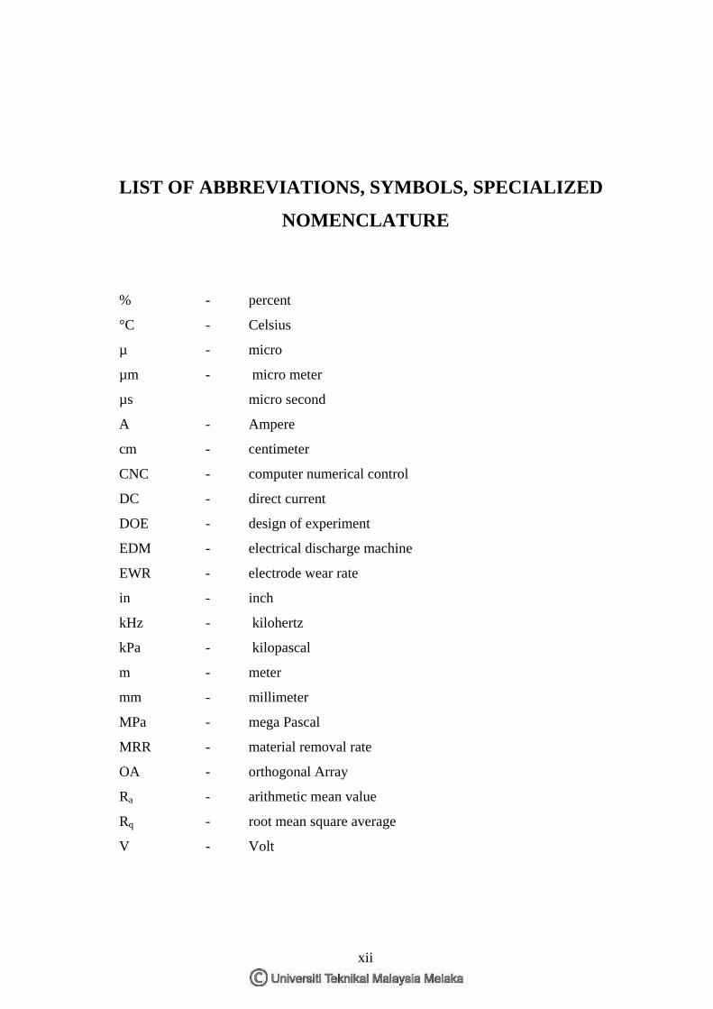
LIST OF ABBREVIATIONS, SYMBOLS, SPECIALIZED
NOMENCLATURE
% - percent
°C - Celsius
µ - micro
µm - micro meter
µs micro second
A - Ampere
cm - centimeter
CNC - computer numerical control
DC - direct current
DOE - design of experiment
EDM - electrical discharge machine
EWR - electrode wear rate
in - inch
kHz - kilohertz
kPa - kilopascal
m - meter
mm - millimeter
MPa - mega Pascal
MRR - material removal rate
OA - orthogonal Array
Ra - arithmetic mean value
Rq - root mean square average
V - Volt
xii

CHAPTER 1 INTRODUCTION
1.0 Background
Nowadays the important use of Electro Discharge Machine (EDM) has been known
worldwide. EDM has rapidly placed alongside the milling and the grinding
equipments. The most common use EDM is machining dies, tools and molds made
from hardened steel, high-speed steel, tungsten carbide and other work piece
materials. Beside of that, EDM also has replaced many of the traditional machining
process in some applications. EDM has many advantages. The most important thing
is no force or no contact involve in the machining process. Therefore no tool or work
piece force involve in the machining process like milling and grinding process in
traditional machining.
It as well suited for making complex or fragile parts that cannot be done by the
traditional machining process. Instead of that EDM process also can be used for high
ratio deep cavity machining for making deep holes or slots with only using long
electrodes. This process will keep the precision of making deep cavity machining
compared with the traditional machining. Since the EDM process do not involve with
forces, though material like titanium and nitralloy can be process easily. This make
the EDM process is very important in producing part using though material like in
the aerospace industries, military and car racing technologies.
The EDM process also not involve with the rotation of the tool. Therefore no
problem will occur when machining sharp internal corners, the dimension maintain
at high accuracy of precision. Compared with the traditional machining, problem will
1
occur for machining internal corner where it all depends to the radius of rotating tool.
EDM also has low cost for tooling. No die set needed to do EDM machining process.
Therefore complex parts and prototypes can be made easily.
At last, EDM is a system that can produce high quality and high precision products
in a very efficient way to meet the requirement and demand for precision machine
tools. The study of EDM process will make the evolution of the EDM grow and the
knowledge will play important role in the manufacturing process industry.
The typical parameter used in EDM such Electrode material, Electrode polarity (+/-),
pulse current Ip (A), pulse duration time (micro s), pulse off time to (micro s),
average voltage U (V), working current density Id (A/cm2), Average current I (A),
open gap voltage Vo (V), Dielectric and flushing mode.
The most important machining performance of EDM is the removal rate, the
electrode wear, accuracy and surface texture. In this paperwork “The effect of EDM
die sinking parameters on surface roughness for machining tool steel material” is
discussed. There are many parameters in EDM die sinking that can be considered.
Three level process parameter such as voltage (V), pulse OFF time (µs) and peak
current (A) with two level of factor (High) and (Low) considered for this study. By
controlling the chosen processes parameters the required surface roughness will be
derive and the final result will be evaluate in order to get the most significant
machining parameter that influences fine surfaces roughness.
1.1 Problem Statement
There have been many published studies considering surface finish of machined
materials by EDM. It was noticed that various machining parameters influenced
surface roughness and setting possible combination of these parameters were
difficult to produce optimum surface quality. The influences of some machining
parameters such as pulsed current, pulse time, pulse pause time, voltage, dielectric
2
liquid pressure and electrode material have been examined. One study examined P20
tool steel and provided useful information the effects of some machining parameters
on surface roughness, but the selected of pulsed current values was very low 1–8A
.The present study examines the effects of pulsed current, pulse time and pulse pause
time on surface roughness in the 40CrMnNiMo864 composite (AISI P20) tool steel.
Therefore the effect of EDM parameter for parameters voltage (V), pulse OFF time
(µs) and peak current (A) for machining tool steel with grade AISI D2 still being
studied to get the significant parameter and optimum value for machining
performance of tool steel material alloy steel (AISI D2 cold-work).
1.2 Objectives
The purposes of this project are:
i. To study the effect of EDM die sinking for three chosen parameters voltage
(V), pulse OFF time(µs) and peak current (A) on surfaces roughness for
machining tool steel.
ii. To evaluate the quality of the surface roughness that produced from the EDM
machining of tool steel.
iii. To find significant parameter and optimum value of surfaces roughness from
the surfaces quality evaluation.
1.3 Scope and limitation
Scope of study including:
Run a machining process using EDM die sinking advanced machine type Sodick
LN2/LQ Series to examine methodically and in detail the machining performance
(surfaces roughness) in CNC laboratory Fasa B, UTeM. This project focuses on
study the effect of working surface and the parameter factor chosen was the Voltage
(V), Pulse OFF (µs) and Peak Current (A). Design of Experiment (DOE) will be
3

implementing to know how many times machining process should be run. Where the
chosen parameter was set in proportion with the DOE and the other parameters
remain constant. The material to be tested is tool steel D2-AISI Cold-Work and the
electrode were copper electrode. At the end of machining process, surface roughness
(Ra) value of the working surfaces will be evaluating using Portable Surface
Roughness Tester (SJ 301). Finally, DOE approach was apply to analyze the most
significant factor that influences the optimum value of the machining performance
using MINITAB software. Then from the result obtained, the comparison of the
surface roughness between the set of experiment using different level of parameter
setting will be discussed.
4

CHAPTER 2 LITERATURE REVIEW
2.1 Electrical Discharge Machining (EDM)
Electric discharge machining (EDM) is one of the most popular non-traditional
material removal processes and has became a basic machining method for the
manufacturing industries of aerospace, automotive, nuclear, medical and die-mold
production. The theory of the process was established by two Soviet scientists B.R.
and N.I. Lazarenko in the middle of 1940s. They invented the relaxation circuit and a
simple servo controller tool that helped to maintain the gap width between the tool
and the workpiece. This reduced arcing and made EDM machining more profitable
and produced first EDM machine in 1950s. Major development of EDM was
observed when computer numerical control systems were applied for the machine
tool industry. Thus, the EDM process became automatic and unattended machining
method (Kiyak and Cakir, 2007).
From the machining technique point of view, electro discharge machining (EDM) is
classified as a non-traditional machining technique. This technique has been widely
used in modern metal-working industry and its versatility and ability to cut fully
hardened steels has enabled it to be widely accepted, especially in the die making
industry in addition to high speed machining applications (Haron et al 2001).
The basic process in EDM is carried out by producing controlled electric sparks
between a tool (electrode) and the workpiece, both of which are immersed in a
dielectric fluid. The electric spark raises the surface temperature of both the electrode
and workpiece to a point where the surface temperatures are in excess of the melting
5
or even boiling points of the substances. Metal is thus primarily removed in the
liquid and vapour phases. By controlling the electrical parameters, removal of
material may be confined to some extent to the workpiece (Haron et al 2001).
Wear of the tool (electrode), however, cannot be ignored because when this occurs
the geometrical characteristics of the electrode will not be reproduced on the
workpiece. The surface generated by EDM consists of debris, which has been melted
or vapourised during machining, lying on or incorporated into the cratered spark-
eroded surface. This resulting product of the erosion process, commonly known as
debris, has an important relation to the various aspects of EDM. Debris formation is
analog to chip formation in traditional machining, and normally debris has a
spherical shape with slight ellipticity. Usually, the size as well as the formation of
debris depends on the current supplied during machining (Haron et al 2001).
Electrical discharge machining EDM, or spark machining, as it also called, removes
material with repetitive spark discharges from a pulsating DC power supply, with a
dielectric flowing between the workpiece and tool (Boothroyd and Knight, 2006).
The process uses thermal energy to generate heat that melts and vaporizes the
workpiece by ionization within the dielectric medium. The electrical discharges
generate impulsive pressure by dielectric explosion to remove the melted material.
Thus, the amount of removed material can be effectively controlled to produce
complex and precise machine components. However, the melted material is flushed
away incompletely and the remaining material resolidifies to form discharge craters.
As a result, machined surface has microcracks and pores caused by high temperature
gradient which reduces surface finish quality (Kiyak and Cakir, 2007).
6
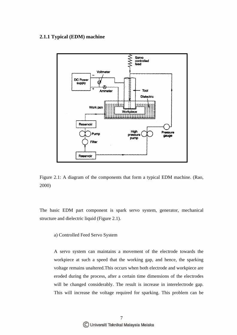
2.1.1 Typical (EDM) machine
Figure 2.1: A diagram of the components that form a typical EDM machine. (Rao,
2000)
The basic EDM part component is spark servo system, generator, mechanical
structure and dielectric liquid (Figure 2.1).
a) Controlled Feed Servo System
A servo system can maintains a movement of the electrode towards the
workpiece at such a speed that the working gap, and hence, the sparking
voltage remains unaltered.This occurs when both electrode and workpiece are
eroded during the process, after a certain time dimensions of the electrodes
will be changed considerably. The result is increase in interelectrode gap.
This will increase the voltage required for sparking. This problem can be
7