Study The Behaviour Of Seismic Evaluation Of Multistoried...
14
International Journal of Scientific Engineering and Applied Science (IJSEAS) – Volume‐3, Issue‐9, September 2017 ISSN: 2395‐3470 www.ijseas.com 146 Study The Behaviour Of Seismic Evaluation Of Multistoried Building With Floating Columns Preethi G 1 , Sudha P H 2 , Maganur D S 3 1 Research Scholar, STJIT, Ranebennur, Karnataka, India 2 Assistant Professor Department of Civil Engineering, STJIT, Ranebennur, Karnataka, India 3 Professor & HOD of Civil Engineering, STJIT, Ranebennur, Karnataka, India ABSTRACT Structural Engineering is a piece of Civil Engineering managing the investigation and outline (Design) of structures that sustain or oppose loads. This undertaking managing the investigation of seismic examination of multi-storied building with and without floating column. The building containing G+8 structures has been chosen for completing the undertaking work. In present situation structures with Floating column is an ordinary component in the cutting edge multi- story development in urban India. Such elements are exceedingly undesirable in building inherent seismically dynamic territories (regions). This study highlights the significance of unequivocally perceiving the vicinity of the Floating column in the examination of building. The Equivalent Static Analysis and Response Spectrum Analysis is done by utilizing Extended Three Dimensional Analysis of Building Systems (ETABS) form 15.2.2 product., examination consequences of the multi-story building, for example, Building displacement, storey drift, and Base shear were thought about in this work. The qualities got from results are taken and graphs are plotted for both with and without Floating column models and after that examination of these models are been introduced. At last, this will help us to locate the different investigative properties of the structure and we might likewise have an extremely precise and conservative configuration for the structure.
Transcript of Study The Behaviour Of Seismic Evaluation Of Multistoried...

International Journal of Scientific Engineering and Applied Science (IJSEAS) – Volume‐3, Issue‐9, September 2017 ISSN: 2395‐3470
www.ijseas.com
146
Study The Behaviour Of Seismic Evaluation
Of Multistoried Building With Floating
Columns
Preethi G1, Sudha P H2, Maganur D S3 1Research Scholar, STJIT, Ranebennur, Karnataka, India
2Assistant Professor Department of Civil Engineering, STJIT, Ranebennur, Karnataka, India 3Professor & HOD of Civil Engineering, STJIT, Ranebennur, Karnataka, India
ABSTRACT
Structural Engineering is a piece of Civil Engineering managing the investigation and outline
(Design) of structures that sustain or oppose loads. This undertaking managing the investigation
of seismic examination of multi-storied building with and without floating column. The building
containing G+8 structures has been chosen for completing the undertaking work. In present
situation structures with Floating column is an ordinary component in the cutting edge multi-
story development in urban India. Such elements are exceedingly undesirable in building
inherent seismically dynamic territories (regions). This study highlights the significance of
unequivocally perceiving the vicinity of the Floating column in the examination of building. The
Equivalent Static Analysis and Response Spectrum Analysis is done by utilizing Extended Three
Dimensional Analysis of Building Systems (ETABS) form 15.2.2 product., examination
consequences of the multi-story building, for example, Building displacement, storey drift, and
Base shear were thought about in this work. The qualities got from results are taken and graphs
are plotted for both with and without Floating column models and after that examination of these
models are been introduced. At last, this will help us to locate the different investigative
properties of the structure and we might likewise have an extremely precise and conservative
configuration for the structure.

International Journal of Scientific Engineering and Applied Science (IJSEAS) – Volume‐3, Issue‐9, September 2017 ISSN: 2395‐3470
www.ijseas.com
147
1 INTRODUCTION
1.1 GENERAL In modern period, multi-storey buildings in metropolitan cities are required to have column free
space due to lack of space, more population and also for aesthetical point of outlook, functional
requirements and also For the purpose of parking hall, usually the ground storey is kept free
without any constructions, excluding the columns which transmit the structure weight to the
land. For a lodge or commercial building, where the lower floors contain dinner halls, forum
rooms, lobbies, show rooms or parking areas, large interrupted space necessary for the
movement of people or vehicles. Narrowly spaced columns based on the plan of higher floors are
not desirable in the lower floors. For this, buildings are provided with floating columns at
different storey. These floating columns are highly inconvenient in a building which is built in
high seismic areas. The seismic forces that are initiated at various stories in a structure need to be
passed down throughout the elevation to the ground by the undeviating pathway. Divergence in
this load transmits way results in reduced performance of the structure. The performance of a
building at some point in seismic activity depends significantly on it’s on the whole shape,
dimension and geometry, in adding to how the earthquake forces are conceded to the land.
Structures that have smaller number columns or walls in a particular floor or with oddly giant
floor be likely to break or fail which is begined in that floor.
1.2 Definition of Floating Column
The floating column is a vertical element which rest on a beam and doesn’t have groundwork.
The floating column act as a concentrated load on the beam and this beam transfers the load to
the columns below it. But such column cannot be implemented easily to build practically since
the true columns below the termination level are not constructed with care and hence finally
cause to collapse.

International Journal of Scientific Engineering and Applied Science (IJSEAS) – Volume‐3, Issue‐9, September 2017 ISSN: 2395‐3470
www.ijseas.com
148
Fig. 1.1 Floating Column
Fig. 1.2 Park Avenue South in New York

International Journal of Scientific Engineering and Applied Science (IJSEAS) – Volume‐3, Issue‐9, September 2017 ISSN: 2395‐3470
www.ijseas.com
149
1.3 Objectives and scope of present work
Following are the objectives of the present study
1. To analyse the RCC multi-storey structure with and without floating column for
seismic forces.
2. Modelling has to be done by using Extended Three Dimensional Analysis of Building
System (ETABS) of version 15.2.2
3. The Equistatic Analysis and Response Spectrum Analysis is carried out for the multi-
storey building with and without floating column.
4. Examine various responses such as Base shear, Lateral displacement, and Storey drift
of building with floating column & without floating column.
2 BUILDING CONFIGURATIONS
2.1 Model 1: In this model the building without floating column is considered, this model is
analyzed for zone 2, zone 3, zone 4 and zone 5
Fig 2.1: Elevation of Model 1

International Journal of Scientific Engineering and Applied Science (IJSEAS) – Volume‐3, Issue‐9, September 2017 ISSN: 2395‐3470
www.ijseas.com
150
2.2 Model 2: In this model 2 the floating column is introduced at 1st floor at the outer section of
the plan. This is analyzed for all the zones like zone 2, zone3, zone4 and zone 5
Fig 2.2: Elevation of the Model 2
2.3 Model 3: In this model 3 the floating column is introduced at 5th floor at the outer section of
the plan. This is analyzed for all the zones like zone 2, zone3, zone4 and zone 5
Fig 2.3: Elevation of the Model 3

International Journal of Scientific Engineering and Applied Science (IJSEAS) – Volume‐3, Issue‐9, September 2017 ISSN: 2395‐3470
www.ijseas.com
151
3 METHODOLOGY
1. In this work G+8 storey building is analysed using ETABS 2015 software with regular plan
2. Floating column is introduced according to the functional requirement
3. Equivalent static force method (static analysis) and Response spectrum method (Dynamic
analysis) carried for different zones
4. Generation of response spectrum for soil type medium for the seismic zone2 to 5 according to
IS 1893: 2002 has been used for the dynamic analysis.
5. The results obtained from the finite element analysis are listed, discussed and finally drawn
the conclusion.
3.1 METHODSOFSEISMICANALYSISOFSTRUCTURE
Different strategies for contrasting complication have been created for the seismic examination
or analysis of structures. They can be named below:
Equivalent Static analysis or Static analysis
Dynamic analysis
The methods of Dynamic analysis are:
Response Spectrum Method
3.1.1 EQUIVALENT STATIC ANALYSIS
In the equivalent static analysis, the theory is made that the structure will react in its basic mode.
This method is well suited for normal building, small rise and average rise buildings. And the
building should not twist as the ground moves and the response is studied from the designed
response spectra. The method followed by calculating the lumped weight and then fundamental
natural period to estimate the base shear and the lateral force distribution at each storey level
using IS 1893(part 1)-2002. Static loads don’t vary with time as like dynamic. The static analysis
is the mainly simple one-it necessitate a smaller amount computational endeavours and is in view
of formulation given in the code of practice. The drawback of this is that only single mode of
vibration of structure is used for analysing.
3.1.2RESPONSE SPECTRUM METHOD

International Journal of Scientific Engineering and Applied Science (IJSEAS) – Volume‐3, Issue‐9, September 2017 ISSN: 2395‐3470
www.ijseas.com
152
The spectrum, which is utilize as seismic in order is the response spectrum of a quake. Actually,
response spectrum of a quake is the most supported seismic info for Earthquake Engineers.
There are various response spectra that are characterized for speaking to the ground movement,
for example, Pseudo speed response spectrum, Displacement response spectrum, Energy
spectrum and Absolute acceleration response spectrum. These spectra additionally demonstrate
the frequency substance of the ground movement, however not as specifically as the Fourier
range does. The absolute acceleration response spectrum is ordinarily utilized as a data for the
response spectrum methods for examination of structures.
The linear dynamic analysis method is also called as Response spectrum method. In this
techniques the ultimate response of a building during a tremor is found specifically from the
quake responses (or design) range. The representation of the max responses of ideal SDOF
frameworks having notable period and damping, during seismic tremor ground motion, the max
response is plotted against the un damped natural period and for different damping values, and
can be communicated regarding most extreme relative displacement or most extreme relative
speed.
The static (corresponding) horizontal force for a tremor is found via completing a modal analysis
of building, and afterward a static analysis of the structure with corresponding (static) lateral
force in every method of vibration is executed to get the wanted responses.
4 RESULTS AND DISCUSSIONS
4.1 STATIC ANALYSIS
4.1.1 Lateral Displacement
The below results shows the variation of Displacement in X-direction for Zone 2 and Soil
condition is Medium.
MODEL 1 MODEL 2 MODEL 3 STOREY UX IN MM UX IN MM UX IN MM
0 0.313 0.225 0.305 1 2.004 1.95 2.008 2 4.755 5.261 4.762 3 8.369 9.402 8.332 4 12.316 13.662 12.238 5 16.122 17.818 16.012
International Journal of Scientific Engineering and Applied Science (IJSEAS) – Volume‐3, Issue‐9, September 2017 ISSN: 2395‐3470
www.ijseas.com
153
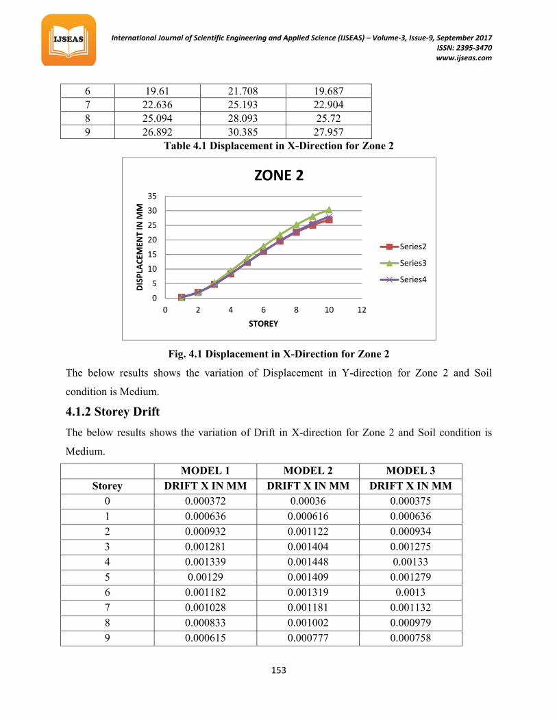
Table 4.1 Displacement in X-Direction for Zone 2
Fig. 4.1 Displacement in X-Direction for Zone 2
The below results shows the variation of Displacement in Y-direction for Zone 2 and Soil
condition is Medium.
4.1.2 Storey Drift
The below results shows the variation of Drift in X-direction for Zone 2 and Soil condition is
Medium.
MODEL 1 MODEL 2 MODEL 3
Storey DRIFT X IN MM DRIFT X IN MM DRIFT X IN MM
0 0.000372 0.00036 0.000375
1 0.000636 0.000616 0.000636
2 0.000932 0.001122 0.000934
3 0.001281 0.001404 0.001275
4 0.001339 0.001448 0.00133
5 0.00129 0.001409 0.001279
6 0.001182 0.001319 0.0013
7 0.001028 0.001181 0.001132
8 0.000833 0.001002 0.000979
9 0.000615 0.000777 0.000758
0
5
10
15
20
25
30
35
0 2 4 6 8 10 12
DISPLA
CEM
ENT IN M
M
STOREY
ZONE 2
Series2
Series3
Series4
6 19.61 21.708 19.687 7 22.636 25.193 22.904 8 25.094 28.093 25.72 9 26.892 30.385 27.957

International Journal of Scientific Engineering and Applied Science (IJSEAS) – Volume‐3, Issue‐9, September 2017 ISSN: 2395‐3470
www.ijseas.com
154
Table 4.2 Drift in X-Direction for Zone 2
Fig. 4.2 Drift in X-Direction for Zone 2
From this graph it is clear that drift in X –Direction for model 3 and model 2 is max when
compared to the model 1
4.1.3 Base Shear
The below results shows the variation of Base Shear in X-direction for Zone 2 and Soil condition
is Medium.
Model 1 Model 2 Model 3
Storey VX in KN VX in KN VX in KN
Base 1205.773 1204.254 1204
Table 4.3 Base Shear in X-Direction for Zone 2
0
0.0002
0.0004
0.0006
0.0008
0.001
0.0012
0.0014
0.0016
0 2 4 6 8 10 12
DRIFT IN M
M
STOREY
ZONE 2
Series1
Series2
Series3

International Journal of Scientific Engineering and Applied Science (IJSEAS) – Volume‐3, Issue‐9, September 2017 ISSN: 2395‐3470
www.ijseas.com
155
Fig. 4.3 Base Shear in X-Direction for Zone 2
From the above charts it is clear that model 1 has maximum Base shear compared to other
models, hence the stiffness of model 1 is more than the other models
4.2 RESPONSE SPECTRUM ANALYSIS
4.2.1 Lateral Displacements
The below results shows the variation of Displacement in X-direction for Zone 2 and Soil
condition is Medium.
MODEL 1 MODEL 2 MODEL 3
STOREY UX IN MM UX IN MM UX IN MM 0 0.089 0.334 0.337 1 0.579 1.95 2.008
1203
1203.5
1204
1204.5
1205
1205.5
1206
BASE
BASE SHEA
R IN
KN
ZONE 2
Series1
Series2
Series3

International Journal of Scientific Engineering and Applied Science (IJSEAS) – Volume‐3, Issue‐9, September 2017 ISSN: 2395‐3470
www.ijseas.com
156
2 1.366 5.261 4.762
3 2.396 9.402 8.332
4 3.469 13.667 12.078
5 4.52 17.82 15.767
6 5.517 21.709 19.592
7 6.43 25.193 22.904
8 7.225 28.136 25.763
9 7.85 30.385 27.957
Table 4.4 Displacement in X-Direction for Zone 2
Fig. 4.4 Displacement in X-Direction for Zone 2
From this graph it is clear that displacement in X –Direction for model 3 and model 2 is max
when compared to the model 1
4.2.2 Storey Drift
The below results shows the variation of Drift in X-direction for Zone 2 and Soil
condition is Medium.
MODEL 1 MODEL 2 MODEL 3 STOREY DRIFT X IN MM DRIFT X IN MM DRIFT X IN MM
0 0.00009 0.00036 0.000375 1 0.000175 0.000616 0.000636 2 0.000279 0.001122 0.000934
0
5
10
15
20
25
30
35
0 2 4 6 8 10
DISPLA
CEM
ENT IN M
M
STOREY
ZONE 2
Series1
Series2
Series3

International Journal of Scientific Engineering and Applied Science (IJSEAS) – Volume‐3, Issue‐9, September 2017 ISSN: 2395‐3470
www.ijseas.com
157
3 0.00037 0.001404 0.001275 4 0.000387 0.001448 0.00133 5 0.000381 0.001409 0.001279 6 0.000362 0.001319 0.0013 7 0.000332 0.001181 0.001132 8 0.000289 0.001002 0.000979 9 0.000234 0.000777 0.000642
Table 4.5 Drift in X-Direction for Zone 2
Fig. 4.5 Drift in X-Direction for Zone 2
From the above graph it is shows that compared to model 1 the storey drift in X-Direction
increases for model 2 and for model 3.
CONCLUSION
From this present work the following observations were made and concluded the things which is stated as below
The structure without floating column is much more stiffer than the structure with
floating column
0
0.0002
0.0004
0.0006
0.0008
0.001
0.0012
0.0014
0.0016
0 2 4 6 8 10
DRIFT IN M
M
STOREY
ZONE 2
Series1
Series2
Series3

International Journal of Scientific Engineering and Applied Science (IJSEAS) – Volume‐3, Issue‐9, September 2017 ISSN: 2395‐3470
www.ijseas.com
158
It is observed that the displacement of the structure with floating column is maximum
when compare to the structure without floating column
The displacement of the structure increases with increase the storey number so the
displacement is increases from lower storey to higher storey
It is also observed that the lateral displacement of the structure increases when we shift
the floating column towards the higher storey
The lateral displacement values increases with increase in the zones displacement values
increase for zone 2, zone 3, zone 4 and zone 5 respectively
The Base Shear is minimum for the structure without floating when compared to the
structure with floating column
Hence it is observed that the structure without floating column is more stiffer when
compared to structure with floating column
The structure without floating column the storey drift is minimum when compared to the
structure with floating column
From this experiment it is concluded that the structure with floating column at higher
floor is must be avoided
If floating column is more needed as the aesthetic and functional point view, it is advisable to perform the sequentional analysis.
Futurescope
This analysis can be carried out for remaining soil types like Hard soil and Soft soil
This analysis can be carried out for irregular building shapes
This can be carried out for different location of the floating columns
This work can be made for the floating columns with bracings
REFERENCES
[1] Pankaj Agarwal, Shrikhande Manish (2009), “Earthquake resistant design of
structures”, PHI learning private limited, New Delhi.

International Journal of Scientific Engineering and Applied Science (IJSEAS) – Volume‐3, Issue‐9, September 2017 ISSN: 2395‐3470
www.ijseas.com
159
[2] Arlekar Jaswant N, Jain Sudhir K & Murty C.V.R, (1997), “Seismic Response of RC
Frame Buildings with Soft First Storeys”. Proceedings of the CBRI Golden Jubilee
Conference on Natural Hazards in Urban Habitat, 1997, New Delhi.
[3] Awkar J C and Lui E M, “Seismic analysis and response of multi-storey semi rigid
frames”, Journal of Engineering Structures, Volume 21, Issue 5, Page no: 425-442,
1997.
[4] Balsamoa A, Colombo A, Manfredi G, Negro P & Prota P (2005), ”Seismic behavior of
a full-scale RC frame repaired using CFRP laminates”, Engineering Structures 27
(2005) 769-780.
[5] Bardakis V G, Dritsos S E(2007), “Evaluating assumptions for seismic assessment of
existing buildings “.Soil Dynamics and Earthquake Engineering 27 (2007) 223–233.
[6] Brodericka B M, Elghazouli A Y & Goggins J (2008), “Earthquake testing and
response analysis of concentrically-braced sub-frames”, Journal of Constructional Steel
Research Volume 64, Issue 9, Page no: 997-1007.
[7] Srikanth M K & Yogeendra R Holebagilu (2014), “seismic response of complex
buildings with floating column for zone ii and zone v”, International journal of
Engineering Research, Volume 2, issue 4.
[8] A P Mundada & S G Sawdatkar (2014), “Comparative Seismic Analysis of Multi-
storey Building with and without Floating Column”, International Journal of Current
Engineering and Technology.
[9] Mayuri D Bhagwat & Dr. P S Patil (2014), “Comparative study of performance of RCC
multi-storey building for Koyna and Bhuj Earthquakes”, International Journal of
Advanced Technology in Engineering and Science, Volume No.02, Issue No. 07, July.
[10] Prerna Nautiyal, Saleem Akhtar & Geeta Batham (2014), “Seismic Response
Evaluation of RC frame building with Floating Column considering different Soil
Conditions”, International Journal of Current Engineering and Technology.