Study Report SR462 Comparative study of corrosion rates in ...
21
Study Report SR462 [2021] Comparative study of corrosion rates in vented and unvented roof cavities Stephan Rupp
Transcript of Study Report SR462 Comparative study of corrosion rates in ...

Study Report
SR462 [2021]
Comparative study of
corrosion rates in vented and
unvented roof cavities
Stephan Rupp

1222 Moonshine Rd, RD1, Porirua 5381
Private Bag 50 908, Porirua 5240 New Zealand
branz.nz
© BRANZ 2021
ISSN: 1179-6197

Study Report SR462 Comparative study of corrosion rates in vented and unvented roof cavities
i
Acknowledgements BRANZ would like to thank Transpower who have given us access and provided transport to the exposure site situated at their Oterangi Bay station. Thanks are also due to my colleague at BRANZ Zhengwei Li who gave valuable input to this study.

Study Report SR462 Comparative study of corrosion rates in vented and unvented roof cavities
1
Comparative study of corrosion rates in
vented and unvented roof cavities
BRANZ Study Report SR462
Author Stephan Rupp
Reference Rupp, S. (2020). Comparative study of corrosion rates in vented and unvented roof cavities. BRANZ Study Report SR462. Judgeford, New Zealand: BRANZ Ltd.
Abstract First-year corrosion rates on mild steel and zinc-galvanised steel samples were evaluated and compared in a passively vented and unvented roof cavity. The experimental set-up in close proximity to the Wellington southern coast was designed to be similar to a domestic skillion roof space covered by a standard metal long-run roof cladding. Outside reference samples confirmed the extremely corrosive environment. The results indicate an increased corrosion rate in the vented cavity. However, all samples are still classified as having a low or very low corrosion rate according to relevant standards.
Keywords Corrosion rate, passive ventilation, roof cavity.

Study Report SR462 Comparative study of corrosion rates in vented and unvented roof cavities
2
Contents
EXECUTIVE SUMMARY .................................................................................... 3
1. INTRODUCTION ..................................................................................... 4
2. EXPERIMENTAL SET-UP ......................................................................... 6
Test structure ....................................................................................... 6
Passive ventilation elements ................................................................... 9
Samples and sample placement ............................................................ 11
Sample analysis .................................................................................. 12
3. RESULTS AND DISCUSSION ................................................................. 13
Reference samples .............................................................................. 13
Vented/unvented cavity samples .......................................................... 14
4. CONCLUSIONS ..................................................................................... 17
REFERENCES ................................................................................................ 18
Figures
Figure 1. Test structure located at the remote south coast of Wellington. ................... 6
Figure 2. Vented and unvented roof cavity of the test structure with metal coupons already in place. .......................................................................................... 7
Figure 3. Over-fascia vent next to a vented batten, terminating the lower end of the roof cavity. .................................................................................................. 8
Figure 4. Vent opening on the seaward side of the structure. ..................................... 8
Figure 5. Roofing underlay being installed over the vented cavity. .............................. 9
Figure 6. Graphical representation of the vented cavity in CONTAM. ......................... 10
Figure 7. Reference samples mounted in place. ...................................................... 12
Figure 8. Mild Steel reference sample 27 (horizontal) after 1 year – front and rear . .. 13
Figure 9. Galvanised steel sample 25 (vertical) after 1 year – front and rear. ............ 14
Figure 10. Corrosion rates for all mild steel samples at the various orientations inside the roof test structure. ............................................................................... 15
Figure 11. Corrosion rates for all galvanised steel samples at the various orientations inside the test structure. ............................................................................. 15
Tables
Table 1. Characterisation of airflow resistance of the two vent elements used. .......... 10
Table 2. Sample nomenclature, placement and orientation inside the cavities. ........... 11
Table 3. ISO 9223:2012 atmospheric corrosivity classification based on first-year corrosion rates in g/m²/year. ...................................................................... 13
Table 4. Measured first-year corrosion rates of the outside reference samples. .......... 14

Study Report SR462 Comparative study of corrosion rates in vented and unvented roof cavities
3
Executive summary
The aim of this experimental study was to establish if there is a noticeable and quantifiable increase in the first-year corrosion rates of metal fixtures in roof cavities that have additional passive ventilation elements installed. Such elements may add resilience to a roof space against moisture accumulation and related problems. However, the increased air exchange rates in the cavity might also lead to more salt ingress with a higher corrosivity of any metals in the roof space such as nail plates.
In order to see if such building materials are negatively impacted in their lifetime performance, a comparative experimental study was conducted. A test dwelling at Wellington’s south coast was converted to house two roof cavities, similar to a residential skillion roof cavity. One was equipped with passive ventilation elements and the second space without. Galvanised and mild steel samples were placed inside these cavities at various locations and left there for 12 months. After recovery, the corrosion rates were measured for all samples as well as reference samples that had been placed outside the structure. The first-year corrosion rates for the reference samples confirmed the extremley harsh environment, which was desired to resolve the anticipated small differences between the closed and ventilated test space. All three mild steel and two of the three galvanised steel reference samples fell into the CX Extreme category of ISO 9223:2012 Corrosion of metals and alloys – Corrosivity of atmospheres – Classification, determination and estimation.
Comparing the mild steel and galvanised steel samples inside the vented and unvented cavities, the vented metal samples (coupons) exhibited a higher first-year corrosion rate. This is true for all of the three sample orientations – horizontal, 45° and vertical. The vertical samples, which are most relevant for nail plates in roof trusses, exhibited the smallest difference in corrosity when comparing the vented to the unvented cavity.
While there is a measurable difference in the corrosion rates of the vented and unvented spaces, the overall corrosion rates for both the mild steel and the galvanised steel samples fall into the ISO 9223:2012 C2 Low or C1 Very low category. Bearing in mind the extremely corrosive environment of the site, the observed increase in corrosivity of the vented cavity is considered to be acceptable. This result confirms previous work undertaken by BRANZ where nail plates in well-vented tile roof spaces were examined qualitatively and little corrosion was noted. Adding passive ventilation elements to roof spaces should therefore not have a significant detrimental impact on the lifetime of the metal fasteners.

Study Report SR462 Comparative study of corrosion rates in vented and unvented roof cavities
4
1. Introduction
Traditionally, New Zealand roofs have been constructed as cold roofs – the thermal insulation is placed directly above the ceiling lining, leaving a cavity between the roof cladding and the lining. The volume of this cavity can vary significantly depending on the roof and ceiling design. Conventional truss roof designs with their large volumes are now often replaced by monopitch roofs frequently in combination with a skillion-type ceiling, leaving very small and often inaccessible roof spaces (Pringle, 2018).
The common aspect of all these designs is that the roof cavity is more or less coupled to the outdoor climate. The thermal perimeter of a dwelling does not include the roof space. Temperatures inside the cavity will exhibit much larger oscillation than inside the building. Although the roof cavity temperature will follow the ambient temperature, extreme values above and below the ambient temperature are observed during daytime heating of the enclosed space and night-time cooling, where energy is radiated into a clear sky. The degree of coupling between the roof cavity and the outside climate depends on the air exchange rate between these environments. The type of roof cladding and roofing underlay and the detailing around the perimeter are important factors in determining the roof envelope airtightness. Recently, BRANZ has developed and trialled an experimental procedure to test this airtightness independent of air leakage through the ceiling level of a building (Rupp, Plagmann & Cox-Smith, 2018). The driver for an air exchange is wind action around the building or pressure differences due to the stack effect.
The roof space climate is also coupled to the indoor climate of a building. Thermal conductive losses across the ceiling during the heating season have the potential to raise the temperature in the roof space. If the ceiling level is not an effective air barrier, convective losses are added to the conductive thermal losses. In addition, the movement of inside air into the roof space through any openings at the ceiling level such as old-style downlights, roof access hatches or air-leaky linings may transport significant amounts of water into the roof space. The moisture content inside is typically higher as compared to the outside as human activities release moisture into the building. If this moisture is not removed adequately by ventilation, levels can rise to cause problems. High indoor moisture loads and an easy, quick path for this moisture to migrate into the roof space can also lead to problems there. Roof moisture issues in New Zealand have been described by BRANZ (Rupp & Plagmann 2015, 2018) and others internationally (Roppel, Norris & Lawton 2013; Essah, 2012). While the New Zealand Building Code does not require and prescribe roof space ventilation, BRANZ recommends this to add resilience against potential moisture accumulation.
Roof space ventilation generally describes the practice of providing an intended air exchange mechanism to the cavity in between the roof cladding and the ceiling of a dwelling. This can be achieved by simply designing and installing vent openings around the eaves and the ridge of a roof. The purpose of roof space ventilation in New Zealand’s climatic environment is primarily moisture management (BRANZ, 2018). Moisture entering the roof space from below can potentially condense on cold cladding and underlay surfaces, especially during clear nights where the cladding temperature can fall significantly below ambient temperatures due to radiative heat losses into the open sky. Excessive amounts of water may accumulate over time and may not be removed adequately by natural, limited air exchanges with outside air.

Study Report SR462 Comparative study of corrosion rates in vented and unvented roof cavities
5
While opening the roof cavity to increase the number of air exchanges can help remove excess moisture, it may also have other unintentional consequences. Thermal losses might increase during the heating season as some heat is lost from the conditioned indoor space across the ceiling into the roof space. Increased ventilation of this space may reduce the temperature, leading to a larger temperature gradient across the ceiling.
The other potentially detrimental aspect of increased air exchanges in the roof space is an accelerated corrosion of metal fixtures such as nail plates. The environmental corrosivity in New Zealand with its relatively low man-made pollutants is mainly due to wind-blown chloride deposits and surface wetness (Haberecht & Kear, 2005). Marine-borne aerosols containing salts of sodium chloride (NaCl) and magnesium chloride (MgCl₂) are carried inland from the fetch of the wind, leading to salt deposits on exposed or accessible building surfaces. The corrosion rates encountered at a specific site and part of the building are then dependent on the distance to the sea, the wind patterns, relative humidity, time of wetness and other physical factors. Rain wash plays an important role on external surfaces since it helps to remove salt deposits.
The atmospheric corrosion rates throughout New Zealand are evaluated and mapped on a regular basis. An update was published by BRANZ in 2015 (Li, Marston & Jones, 2015) comparing rates measured in 2011–2014 to 1987–1988. While different sites exhibited different relative behaviours, the first-year corrosion rate from most testing sites in this study was comparable with previous data of the 1980s.
Corrosion rates in New Zealand subfloor environments were investigated in a study by BRANZ in 2016 (McNeil, Li, Cox-Smith & Marston, 2016). In general, it was found that the subfloor environment was more benign from the corrosion point of view compared with atmospheric conditions. However, corrosion samples located near the vent openings were found to exhibit higher corrosion rates then samples located elsewhere. Driving rain entering the subfloor and wetting the samples was believed to cause this.
A qualitative survey on the condition of nail plates and wire ties of seven concrete tile roofed houses near the coast of New Zealand was conducted by BRANZ in 2002 (Jordan, 2002). The study was focused on these types of dwellings because concrete tile roofs did not require a roofing underlay and may consequently have a high ingress of corrosive salt-laden air into the roof space. The houses were generally built in the 1960s so had been exposed to these environmental conditions for 20–30 years. The findings were that the corrosion rates of galvanised fixtures in these roof spaces was generally low. The low corrosivity values were conjectured to be due to either low salt deposition rates due to low air exchange rates or due to a rapid fallout of aerosols once the particles have entered the roof space. The low relative humidity in the roof space, as concluded by timber moisture measurements, was also thought to have a beneficial impact.
In this experimental study, we attempt to quantitatively resolve any differences in the first-year corrosivity of mild steel and galvanised steel samples mounted in a test environment that would closely resemble a passively vented and unvented roof cavity in a very corrosive marine environment. Due to the location of the exposure site close to the sea, no conclusions can be made regarding potential differences in the corrosivity inside vented and unvented roof spaces in geothermally more active areas of New Zealand.
Study Report SR462 Comparative study of corrosion rates in vented and unvented roof cavities
6
2. Experimental set-up
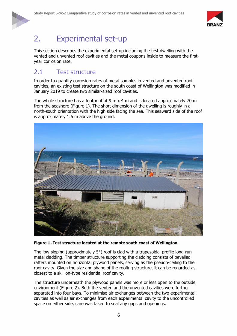
This section describes the experimental set-up including the test dwelling with the vented and unvented roof cavities and the metal coupons inside to measure the first-year corrosion rate.
Test structure
In order to quantify corrosion rates of metal samples in vented and unvented roof cavities, an existing test structure on the south coast of Wellington was modified in January 2019 to create two similar-sized roof cavities.
The whole structure has a footprint of 9 m x 4 m and is located approximately 70 m from the seashore (Figure 1). The short dimension of the dwelling is roughly in a north-south orientation with the high side facing the sea. This seaward side of the roof is approximately 1.6 m above the ground.
Figure 1. Test structure located at the remote south coast of Wellington.
The low-sloping (approximately 5°) roof is clad with a trapezoidal profile long-run metal cladding. The timber structure supporting the cladding consists of bevelled rafters mounted on horizontal plywood panels, serving as the pseudo-ceiling to the roof cavity. Given the size and shape of the roofing structure, it can be regarded as closest to a skillion-type residential roof cavity.
The structure underneath the plywood panels was more or less open to the outside environment (Figure 2). Both the vented and the unvented cavities were further separated into four bays. To minimise air exchanges between the two experimental cavities as well as air exchanges from each experimental cavity to the uncontrolled space on either side, care was taken to seal any gaps and openings.

Study Report SR462 Comparative study of corrosion rates in vented and unvented roof cavities
7
Figure 2. Vented and unvented roof cavity of the test structure with metal coupons
already in place.
The roofing underlay (not installed yet in Figure 2) was glued to the three relevant rafters, further minimising undesirable lateral air exchanges between the cavities.
Passive ventilation elements were installed to the eastern roof cavity. Each of the four bays had ventilated plastic battens1 mounted between the timber purlins and the underlay/roof cladding, giving a total of five horizontal battens. The length of each vented batten was 1.16 m.
The total volume of the four bays of each of the vented and the unvented cavities including the volume of the two soffit areas was approximately 0.6 m3.
The site is very close to the beach with wind-blown sand deposits potentially being a problem. During regular site visits, it was noticed that a small fraction of around 10% of the ventilation openings at the front were blocked by moist sand deposits. The vents were cleaned on each occasion.
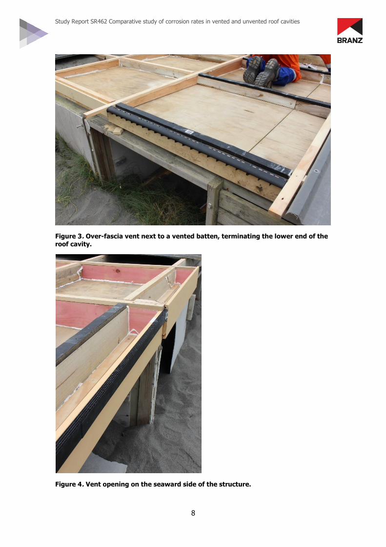
The northern end of the vented cavity was terminated with an over-fascia element (Figure 3). While giving a predefined opening to the roof space, the grid was fine enough to give some protection from insects entering the cavity.
The seaward side of the cavity had an additional vented batten mounted on the fascia board (Figure 4), which was then covered by the ridge flashing.
1 These are commercially available from a number of vendors in New Zealand.
Study Report SR462 Comparative study of corrosion rates in vented and unvented roof cavities
8
Figure 3. Over-fascia vent next to a vented batten, terminating the lower end of the
roof cavity.
Figure 4. Vent opening on the seaward side of the structure.

Study Report SR462 Comparative study of corrosion rates in vented and unvented roof cavities
9
The cavities were then covered with a commercial roof underlay without any mesh support (Figure 5).
Figure 5. Roofing underlay being installed over the vented cavity.
Passive ventilation elements
An experimental measurement of the actual air exchanges in the vented cavity using tracer gas or other methods was not possible due to the remoteness of the location. An alternative approach was to estimate the approximate air exchange rates by charactersing the vent elements individually. The characteristic airflow properties as a function of pressure drop across the element can then be used in a numerical simulation assuming some average wind exposure.
The serial resistance of the installed vents to a mostly pressure-driven air exchange throughout the vented roof cavity is made up of six vented battens and one over-fascia vent element. The performance of the individual vent elements has been tested in our laboratory (Table 1). The airflow rate Q as a function of the pressure difference across the material is described by the leakage function (ASHRAE, 2009, Chapter 16, Equation 40):
𝑸 = 𝒄 ∙ ∆𝒑𝒏 𝑬𝒒 𝟏
where
Q volumetric airflow rate [litres/(s·m)]
c flow coefficient characteristic for the ceiling or fixture [litres/ (s·Pan)]
Δp pressure difference across the element [Pa]
n pressure exponent, describing the nature of the flow (going from a factor of 0.5 indicating turbulent to 1 for a laminar flow) [dimensionless]

Study Report SR462 Comparative study of corrosion rates in vented and unvented roof cavities
10
Table 1. Characterisation of airflow resistance of the two vent elements used.
Vented batten
t = 20 mm, d = 45 mm, l = 1 m
Q [l/s·m] = c·Δpn
5.12
0.629
Over-fascia vent
Q [l/s·m] = c·Δpn
14.32
0.504
These measured characteristics can be used as airflow resistance elements in the numerical simulation tool CONTAM2 to estimate the number of air exchanges in the roof cavity as a function of wind action across the structure. Figure 6 gives a graphical representation of the vented cavity in CONTAM. The four bays, displayed in blue, are separated by the airflow resistance elements (black circles). The white areas represent the smaller soffit area volumes. The figure also indicates the simulated result in terms of pressure drop and flow through the third vented batten for a particular wind direction and speed. For the modelling, it is assumed that the roof and ceiling surfaces are absolutely airtight and any air exchange only occurs through the bays themselves. Thus, the airflow in metres per second given for the second vent element will be identical for all the other elements and indeed for the complete cavity.
Figure 6. Graphical representation of the vented cavity in CONTAM.
2 CONTAM is a numerical simulation software to determine airflow rates through multiple interconnected zones. Developed by the US National Institute of Standards and Technology
(NIST), it is free to download – see https://www.nist.gov/el/energy-and-environment-division-73200/nist-multizone-modeling/software/contam.

Study Report SR462 Comparative study of corrosion rates in vented and unvented roof cavities
11
For this simple approximation to estimate the air exchange rate through the vented cavity, we have taken an average wind speed measured by MetService at Kelburn, Wellington. This long-term average at the standard height of 10 m is 5.2 m/s. Using Table 1 in Chapter 16 of ASHRAE (ASHRAE, 2005), this wind speed at the reference height of 10 m can be converted to an aproximate value at a lower height and a typical terrain topography. In this case, we use an average value of 1 m/s for the dwelling at the test site with a prevailing wind direction of northwest (300°). Using these parameters and the volume of the vented cavity, we arrive at an average air exchange rate of 3.5 ach (air exchanges per hour).
Samples and sample placement
To compare the first-year corrosivition rate inside the vented and unvented roof cavities, mild steel and hot-dip galvanised steel samples were mounted inside the roof cavities at 90° and 45° angles as well as horizontally. Each of the eight bays also had a horizontally mounted stainless steel coupon installed. Bays 1–4 were vented, and bays 5–8 were without vent elements. Bays 1 and 5 were towards the seaside. The pre-cleaned (acetone) metal coupons were of rectangular shape and nominally 120 mm by 80 mm in size with a thickness of 1.2 mm. The weight of each coupon was measured to 0.001 g before being placed in a separate sealed plastic bag. The coupons were mounted to aluminium brackets with nylon fasteners, making sure there was no contact between the aluminium and the metal coupon. In addition, a horizontally mounted stainless steel coupon was installed in each of the eight bays as a reference.
In total, there were 12 galvanised and 12 mild steel samples in each vented and unvented cavity. The position and orientation of each coupon is illustrated in Table 2. Stainless steel samples were also placed inside the structure. However, no corrosion rate could be reliably measured on those and no results are given in this report. Reference samples were installed outside the roof cavities – three mild steel and three galvanised steel samples in the same horizontal, 45° and vertical orientations as inside the roof cavity. A horizontal stainless-steel coupon was also installed for reference (Figure 7).
Table 2. Sample nomenclature, placement and orientation inside the cavities.

Study Report SR462 Comparative study of corrosion rates in vented and unvented roof cavities
12
Figure 7. Reference samples mounted in place.
The samples were installed at the test site in late January 2019 and recovered in early February 2020.
Sample analysis
To determine the first-year corrosion rates, the corrosion products remaining on the metal surfaces were removed by a thorough clean following the procedures recommended by ASTM G1 – 03(2017)e1 Standard practice for preparing, cleaning, and evaluating corrosion test specimens.
• Mild steel samples: 0.5 L/L hydrochloric acid (HCl, specific gravity: 1.19, 38%) + 3.5 g/L hexamethylenetetramine (C6H12N4) at 20–25°C.
• Galvanised (zinc) samples: 100 g/L ammonium chloride (NH4Cl) at 70°C. • Stainless steel samples: 0.1L/L nitric acid (HNO3, specific gravity: 1.42) at 60°C.
The chemically cleaned samples were rinsed with flowing water, dried with hot air and reweighed to determine their mass losses due to atmospheric exposure. Several clean unexposed metal samples were subjected to the same cleaning process, and their mass losses were recorded for corrosion rate measurement correction.

Study Report SR462 Comparative study of corrosion rates in vented and unvented roof cavities
13
3. Results and discussion
Within the map in NZS 3604:2011Timber-framed buildings, all of Wellington is classified as corrosion exposure zone C. The areas within 500 m of the coastline are typically classified as zone D. The first-year corrosion rates in g/m²/year for the various zones and the definition according to ISO 9223:2012 are summarised in Table 3. The site for this experiment, Oteranga Bay on Wellington’s south coast, is extremely corrosive. First-year corrosion rates of around 1,600 g/m²/year have been reported for vertically mounted mild steel samples facing the sea (Li et al., 2015). This very aggressive site seemed appropriate since previous qualitative work on nail plate corrosion in roof spaces showed no significant deterioration (Jordan, 2002). In order to resolve a difference between vented and unvented roof spaces, a highly corrosive environment seemed necessary.
Table 3. ISO 9223:2012 atmospheric corrosivity classification based on first-year
corrosion rates in g/m²/year.
ISO 9223:2012 category
Description Mild steel Zinc NZS 3604:2011 exposure zone
C1 Very low CR<10 CR≤0.7
C2 Low 10<CR≤200 0.7<CR≤5 B
C3 Medium 200<CR≤400 5<CR≤15 C
C4 High 400<CR≤650 15<CR≤30 D
C5 Very high 650<CR≤1,500 30<CR≤60 E
CX Extreme 1,500<CR≤5,500 60<CR≤180
Reference samples
As expected from previous work, the atmospheric first-year corrosion rates on the reference samples outside were extremely high. Figure 8 and Figure 9 show images of the outside reference sample (front and rear) that was installed horizontally. The nomenclature is such that, for the 45° and horizontal samples, ‘front’ means facing upwards, while for the vertical samples, ‘front’ means facing the seaside. The significant corrosion of the mild steel and iron oxide-hydroxide (red rust) can be seen. Corrosion is also visible on the galvanised coupons, especially around the perimeter where small spots of red rust are visible – a clear sign that the protective layer has been removed. The visual appearance of corrosion is very similar for all the outside samples on the front and the rear side.
Figure 8. Mild Steel reference sample 27 (horizontal) after 1 year – front and rear .

Study Report SR462 Comparative study of corrosion rates in vented and unvented roof cavities
14
Figure 9. Galvanised steel sample 25 (vertical) after 1 year – front and rear.
The measured first-year corrosion rates for the outside reference samples are given in Table 4. All outside samples except the horizontal mild steel sample #27 fall into the ISO 9223:2012 CX Extreme category. The horizontal mild steel sample shows lower corrosion rates, however still at the C5 Very high classification.
Table 4. Measured first-year corrosion rates of the outside reference samples.
Coupon Orientation Corrosion rates CR g/m²/year
ISO 9223:2012 category and description
Mild steel #25 Vertical 2956 CX Extreme
Mild steel #26 45° 3014 CX Extreme
Mild steel #27 Horizontal 1099 C5 Very high
Galvanised #25 Vertical 95 CX Extreme
Galvanised #26 45° 87 CX Extreme
Galvanised #27 Horizontal 87 CX Extreme
While mild steel samples previously measured at this site have also fallen within the CX Extreme category (Li et al., 2015), the current results show an even higher corrosion rate by nearly a factor of 2. This difference points towards possible large seasonal variations or a large influence of the sea-spray conditions in slightly different locations on the test site. During routine visits to the site, it was noticed that the horizontal mild steel sample often had sand deposited on its surface, which might have protected the surface from the extreme corrosion rates of the other orientations.
The results confirm very high atmospheric corrosion rates for this chosen test site.
Vented/unvented cavity samples
Looking first at all samples in the vented and unvented cavities irrespective of their position in a particular bay, we find a consistent picture. The corrosion rates of the mild steel samples for all orientations (vertical, 45° and horizontal) are above the respective rates for the unvented cavity. Furthermore, the corrosion rates are highest for the horizontal samples, followed by the 45° coupons. The vertical samples for both the vented and the unvented cavities exhibit the lowest rates. These results are plotted as box-whisker3 plots in Figure 10. The white horizontal bar indicates the median value and the upper and lower limits of the box represent the 75% and 25% quartiles, while the whiskers give upper and lower extreme values.
3 While box-whisker plots are generally used and are more meaningful for much larger datasets, they nevertheless depict our results in an accessible way.

Study Report SR462 Comparative study of corrosion rates in vented and unvented roof cavities
15
Figure 10. Corrosion rates for all mild steel samples at the various orientations
inside the roof test structure.
A similar pattern is obtained for the galvanised steel samples. The corrosion rates of all orientations in the ventilated cavity are higher as compared to the unvented cavity. While again the vertical samples in both cavities show the lowest corrosion rates, there is no significant difference between the 45° and the horizontal samples in the vented and unvented space (Figure 11).
Figure 11. Corrosion rates for all galvanised steel samples at the various
orientations inside the test structure.
The overall results indicate that a higher corrosion rate can be expected in a vented cavity in a severe marine environment as compared to a non-passively vented space. Given the previously observed dependencies between salt-laden aerosols, salt deposits and corrosion, this was not unexpected. However, when looking at the absolute corrosion rates for the mild steel samples as well as for the galvanised samples, these figures are small, even for this extreme environment.
Study Report SR462 Comparative study of corrosion rates in vented and unvented roof cavities
16
All galvanised samples, which are more relevant from a building point of view, in the unvented cavity fall into the ISO 9223:2012 C1 Very low category. The galvanised samples in the vented roof space exhibit a higher corrosion rate but are still either in the ISO 9223:2012 C1 Very low corrosivity classification (the vertical samples) or at the lower end of the ISO 9223:2012 C2 Low corrosivity classification. No samples exceed a corrosion rate of 2 g/m²/year. The mean corrosion rates for these cases are 0.4 and 0.3 g/m²/year respectively. Especially for the vertically installed samples, which is the more relevant orientation for nail plates on roof trusses, there is almost no difference between the vented and unvented space. However, it is necessary to point out that nail plates attached to the timber with their topography may also hold more moisture and salt deposits.
The mild steel samples also end up in similar low corrosivity categories. The vertically mounted samples from all bays both in the vented and unvented cavities fall into the ISO 9223:2012 C1 Very low category (corrosion rates of <10 g/m²/year). The 45° and horizontal mild steel samples in the unvented cavity exhibit corrosion rates largely between 10 and 30 g/m²/year, putting those in the lower range of the ISO 9223:2012 C2 Low classification bracket. Marginally higher corrosion rates were measured in the vented cavity for the mild steel samples of these two orientations. First-year corrosion rates between 26 and 65 g/m²/year were established, with a median of 30 and 39 g/m²/year for the 45° and the horizontal samples respectively. Thus, the two more susceptible orientations of the mild steel coupons in the vented cavity also fall into the ISO 9223:2012 C2 Low classification bracket.

Study Report SR462 Comparative study of corrosion rates in vented and unvented roof cavities
17
4. Conclusions
The experimental study has shown that, in an extremely corrosive marine environment, the first-year corrosion rates of mild steel and galvanised steel samples are higher in an assembly that comes close to a residential, passively vented roof cavity in comparison to an unvented roof space.
Although the absolute salt deposits inside the cavity were not quantified in this study, the conjecture is that an increased air exchange in the roof cavity leads to a higher ingress of marine-borne salt aerosols, which are responsible for the higher corrosivity.
The differences in all three measured sample orientations (horizontal, 45° and 90°) within the cavities can be clearly resolved, confirming the validity of the experimental approach. However, the overall impact of ventilating a roof space on the corrosivity of metal fixtures appears to be low, especially for galvanised samples. All galvanised steel samples in the vented cavity exhibit first-year corrosion rates of less than 2 g/m²/year, putting them in the ISO 9223:2012 C2 Low corrosivity category. This is in comparison to the outside reference samples exhibiting corrosivity rates that fall into the ISO 9223:2012 CX Extreme range.
Based on these results, the installation of passive ventilation openings to roof cavities is not envisaged to have a significant negative impact on the long-term performance of galvanised metal fixtures in these spaces.

Study Report SR462 Comparative study of corrosion rates in vented and unvented roof cavities
18
References
ASHRAE. (2005). 2005 ASHRAE handbook: Fundamentals. Atlanta, GA: American Society of Heating, Refrigerating and Air-Conditioning Engineers
ASHRAE. (2009). 2009 ASHRAE handbook: Fundamentals. Atlanta, GA: American Society of Heating, Refrigerating and Air-Conditioning Engineers
BRANZ. (2018). Roof space ventilation. BRANZ Bulletin BU630. Judgeford, New Zealand: BRANZ Ltd.
Essah, E. A. (2012). Domestic cold pitched roofs in the UK – effect of using different roof insulation materials. International Journal of Ventilation, 11(3), 281–296. https://doi.org/10.1080/14733315.2012.11683988
Haberecht, P.W. & Kear, G. (2005). Stormy seas, salt deposition and environmental corrosivity – a discussion. Paper presented at the 16th International Corrosion Congress, Beijing, China, 19–24 September.
Jordan, L. R. (2002). Survey of nail plate corrosion in the roof space of houses near the coast. Study Report SR114. Judgeford, New Zealand: BRANZ Ltd.
Li, Z., Marston, N. J. & Jones, M. S. (2015). Update of New Zealands’s atmospheric corrosivity map: Part 2. Study Report SR325. Judgeford, New Zealand: BRANZ Ltd.
McNeil, S., Li, Z., Cox-Smith, I. & Marston, N. (2016). Managing subfloor moisture, corrosion and insulation performance. Study Report SR354. Judgeford, New Zealand: BRANZ Ltd.
Pringle, T. (2018). Roof design. Judgeford, New Zealand: BRANZ Ltd.
Roppel, P., Norris, N. & and Lawton, M. (2013, December). Highly insulated, ventilated, wood-framed attics in cool marine climates. Proceedings of Thermal Performance of the Exterior Envelopes of Whole Buildings XII Conference, 389–401.
Rupp, S. & Plagmann, M. (2015). Ventilation dries attic space. Build, 148, 78–79.
Rupp, S. & Plagmann, M. (2018). Too much moisture in the roof. Build, 166, 93–94.
Rupp, S., Plagmann, M. & Cox-Smith, I. (2018). Airtightness of roof cavities. BRANZ Study Report SR401. Judgeford, New Zealand: BRANZ Ltd.