Study on structural behavior of an atmospheric reentry vehicle during ditching
19
POLITECNICO OF TURIN MASTER DEGREE THESIS IN AEROSPACE ENGINEERING Study on structural behavior of an atmospheric reentry vehicle during ditching Supervisors: • Prof. Giulio Romeo – Politecnico of Turin • Ing. Roberto Ullio – Thales Alenia Space Candidate • Maurizio Coltro
-
Upload
goelke -
Category
Technology
-
view
335 -
download
1
Transcript of Study on structural behavior of an atmospheric reentry vehicle during ditching

POLITECNICO OF TURIN
MASTER DEGREE THESIS IN AEROSPACE ENGINEERING
Study on structural behavior of an atmosphericreentry vehicle during ditching
Supervisors:
• Prof. Giulio Romeo – Politecnico of Turin
• Ing. Roberto Ullio – Thales Alenia Space
Candidate• Maurizio Coltro

Part of ESA’s Future Launchers Preparatory Programme has been devoted to optimizing a long-term European roadmap for in-flight experimentation with atmospheric re-entry enabling systems and technologies.
Thesis activity
The Intermediate eXperimental Vehicle (IXV) project is the next core step of this effort.
This work has been developed within the IXV project and with closed collaboration of TAS-I and ESA.
Many thanks to ESA and TAS for their support. Thanks also to Altair Engineering for providing the software suite for the analysis.

The IXV Project
Technology platform
• Intermediate element of technology-effective and cost efficient Europeanroadmap
• Prepare future ambitious operational system developments with limited risksfor Europe
Project objectives
• Design, development, manufacturing, on-ground and in-flight verification of autonomous European lifting and controlled re-entry system
Critical technologies of interest
• Advanced instrumentation for aerodynamics and aerothermodynamics
• Thermal protection and hot-structures solutions
• Guidance, navigation and flight control
Success of IXV mission
• Correct performance of re-entry
• Safe landing and recovery with its experimental data1/17

Experimental measurements
Mockup
• representative of external shape• inertial properties• scale factors
Physical quantities
• accelerations• pressures
Test facility
• electromagnets to release vehicle• high frequency cameras• high pool dimension to perform impact
2/17
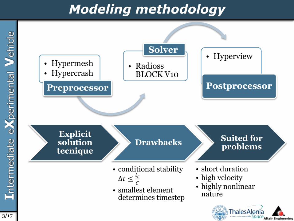
Modeling methodology
• Hypermesh• Hypercrash
Preprocessor
• RadiossBLOCK V10
Solver• Hyperview
Postprocessor
Explicitsolutiontecnique
DrawbacksSuited for problems
• short duration• high velocity• highly nonlinear
nature
3/17
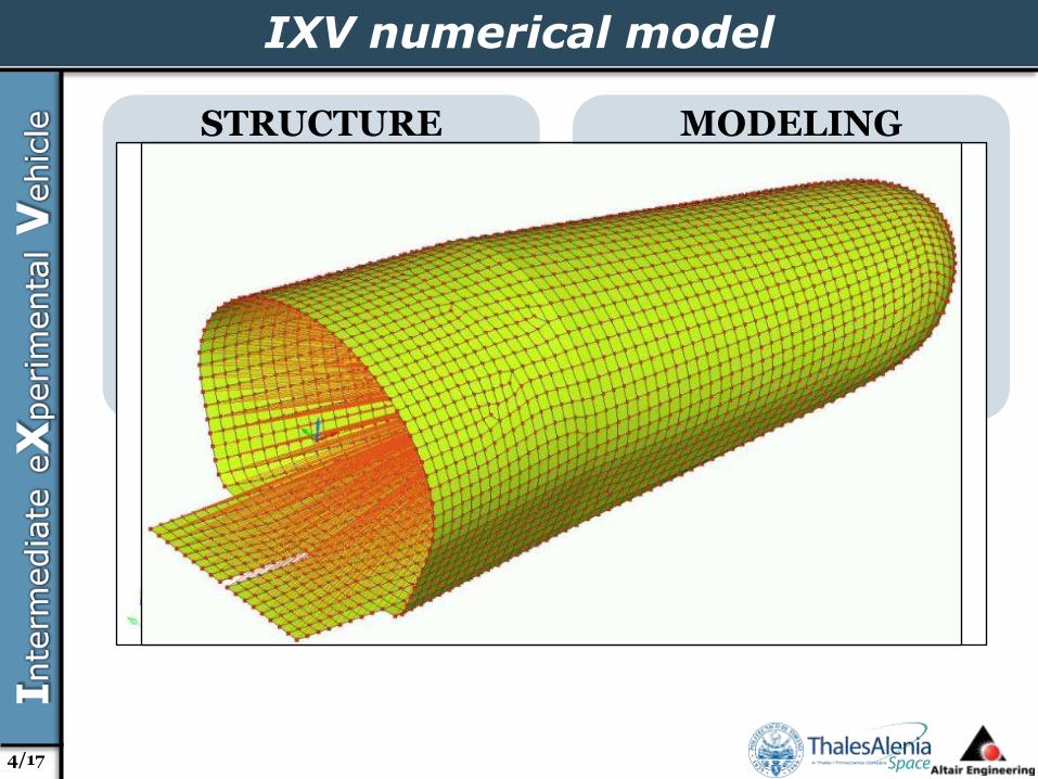
IXV numerical model
STRUCTURE CONFIGURATION
Fuselagecomponents
Flaps assembly
MODELING ASSUMPTIONS
External dimensions takeninto account
Bidimensional rapresentationof surfaces
Rigid body description
RIGID BODY INERTIAL PROPERTIES
Mass Jxx Jyy Jzz
[kg]
27,82 1,17 4,52 4,31
4/17

Fluid numerical model
FLUID DESCRIPTION
LAW37 Biphas
ALE approach
MODELING ASSUMPTIONS
Gas volume extension
Liquid volume extension
5/17

Fluid numerical model
HORIZONTAL EXTENSION
• Limited front dimensions to avoid wave reflection
VERTICAL EXTENSION
• Limited in-deep dimensionsto lighten fluid model
WATER BASIN COMPARISON
Deep water model Shallow water model
Horizontal 1,22 x 2,14 [m] 1,22 x 2,14 [m]
Vertical 0,8 [m] 0,4 [m]
N Elements 335265 189317
CPU Time 8413 [s] 5077 [s]
0 0.02 0.04 0.06 0.08 0.1 0.12 0.14 0.16 0.18
Time [s]
Z Acceleration - Accelerometer T1064-63 (COG)
Shallow Water Model Deep Water Model
6/17
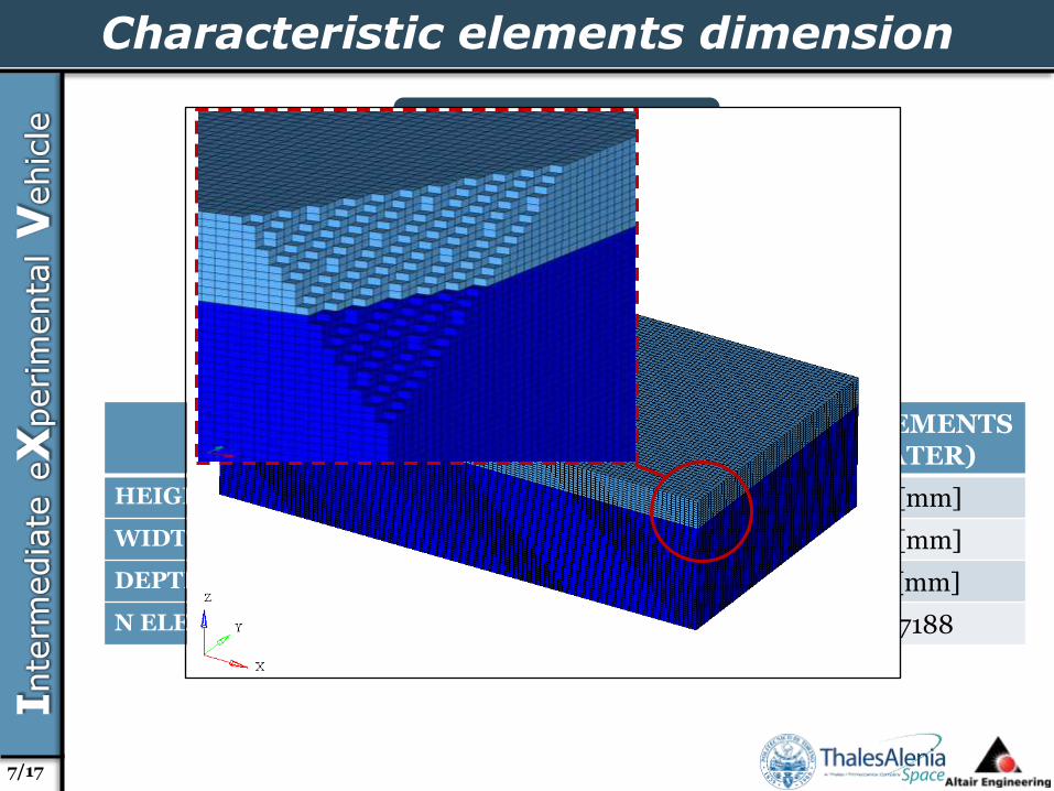
Characteristic elements dimension
Finest mesh normal to
phenomenon
Sensitivityanalysis
2D ELEMENTS (VEHICLE)
3D ELEMENTS (AIR)
3D ELEMENTS (WATER)
HEIGHT 20 [mm] 20 [mm] 20 [mm]
WIDTH 20 [mm] 20 [mm] 20 [mm]
DEPTH / 10 [mm] 10 [mm]
N ELEMENTS 3564 78324 287188
7/17
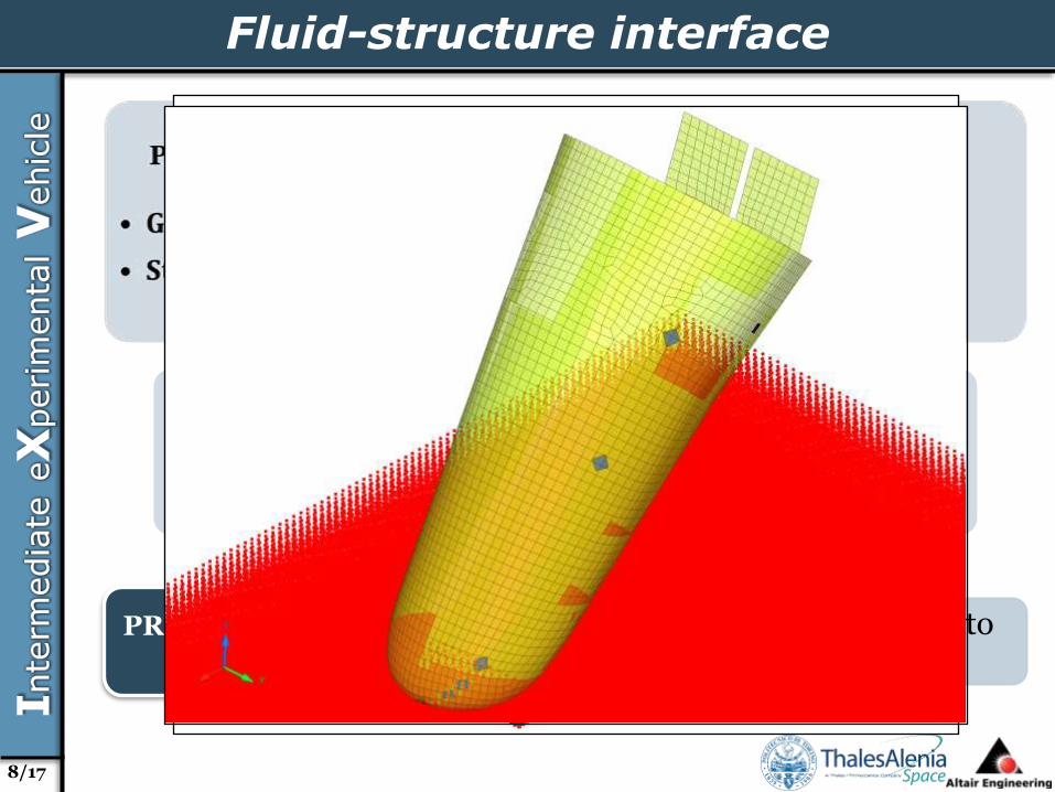
Fluid-structure interface
SENSITIVITY ANALYSIS
PERFORMED
FLUID STRUCTURE INTERFACE
TYPE18
STFAC
Interface stiffness
GAP
Activationdistance
• Single TYPE18 interface torepresent sensors separately
PRESSURE PROBES INTERFACE
8/17

Boundary-initial conditions
• Atmospheric pressure to water free surface
• DYREL dynamic relaxation for convergence
• Gravity load to water volume• Lateral/bottom surfaces locked• FLRD = 1 upper surface
WATER BOUNDARY
CONDITIONS
• Initially locked in all DOFs• Gravity load to master node• Initial velocity to master node• Initial distance from free surface
VEHICLE BOUNDARY
CONDITIONS
9/17
Numerical - Experimental Correlation
• Impact angle 35 deg• Flaps position 0 deg• Vertical velocity 3,4 m/s
FIRST
LOADCASE
• Impact angle 19 deg• Flaps position 0 deg• Vertical velocity 3,4 m/s
SECOND
LOADCASE
• Impact angle 51 deg• Flaps position 21 deg• Vertical velocity 3,4 m/s
THIRD
LOADCASE
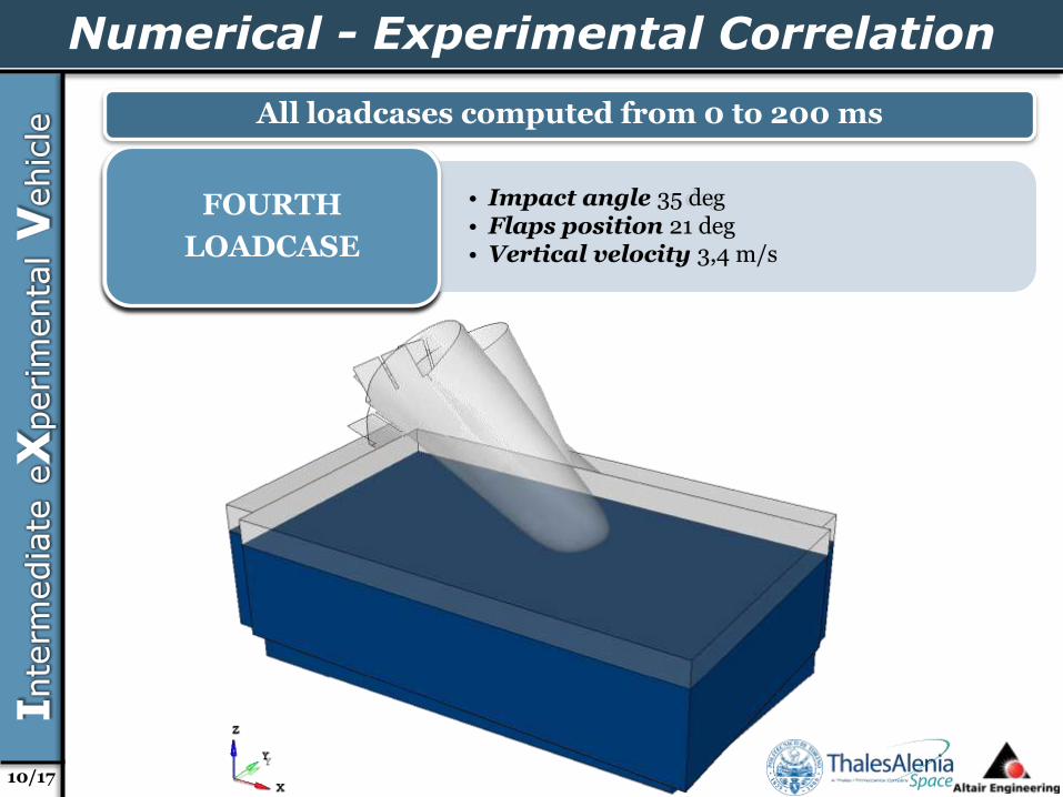
• Impact angle 35 deg• Flaps position 21 deg• Vertical velocity 3,4 m/s
FOURTH
LOADCASE
All loadcases computed from 0 to 200 ms
10/17
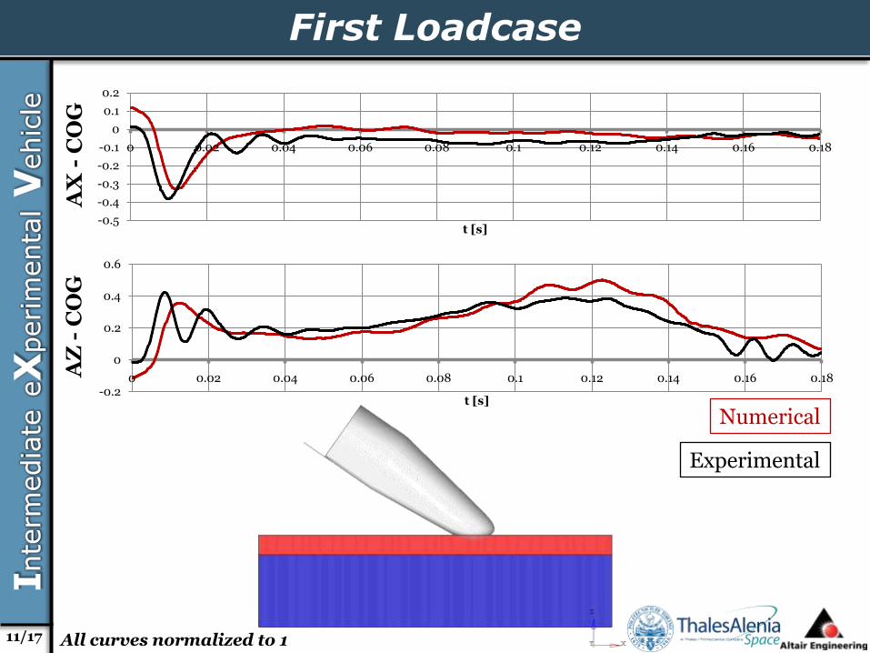
First LoadcaseA
X-
CO
GA
Z -
CO
G
-0.2
0
0.2
0.4
0.6
0 0.02 0.04 0.06 0.08 0.1 0.12 0.14 0.16 0.18
t [s]
-0.5
-0.4
-0.3
-0.2
-0.1
0
0.1
0.2
0 0.02 0.04 0.06 0.08 0.1 0.12 0.14 0.16 0.18
t [s]
Numerical
Experimental
11/17 All curves normalized to 1

Second Loadcase
-0.4
-0.3
-0.2
-0.1
0
0.1
0 0.02 0.04 0.06 0.08 0.1 0.12 0.14 0.16 0.18
t [s]
-0.4
-0.2
0
0.2
0.4
0.6
0.8
0 0.02 0.04 0.06 0.08 0.1 0.12 0.14 0.16 0.18
t [s]
AX
-C
OG
AZ
-C
OG
Numerical
Experimental
12/17 All curves normalized to 1

Third Loadcase
-0.4
-0.3
-0.2
-0.1
0
0.1
0.2
0.3
0 0.02 0.04 0.06 0.08 0.1 0.12 0.14 0.16 0.18
t [s]
-0.2
-0.1
0
0.1
0.2
0.3
0.4
0 0.02 0.04 0.06 0.08 0.1 0.12 0.14 0.16 0.18
t [s]
AX
-C
OG
AZ
-C
OG
Numerical
Experimental
13/17 All curves normalized to 1

Third Loadcase
-0.10
0.00
0.10
0.20
0.30
0.40
0 0.02 0.04 0.06 0.08 0.1 0.12 0.14 0.16 0.18 0.2
t [s]19
de
gS
en
so
r
-0.20
0.00
0.20
0.40
0.60
0.80
0 0.02 0.04 0.06 0.08 0.1 0.12 0.14 0.16 0.18 0.2
t [s]
-0.20
0.00
0.20
0.40
0.60
0.80
1.00
0 0.02 0.04 0.06 0.08 0.1 0.12 0.14 0.16 0.18 0.2
t [s]
35
de
gS
en
so
r5
1 d
eg
Se
ns
or
Numerical Experimental
Numerical Experimental
14/17

Correlation results summary
Main outcomes from acceleration results
• very good correlation at COG in X and Z directions
• satisfactory correlation at NOSE and REAR parts
Main outcomes from pressure results
• good correlation
• impact event chronology
• pressure time history signature
• satisfactory correlation
• pressure peak values
Correlationprocess
model updating activity
• improvement of modellingapproaches
• correction of individualparameters
15/17

Remarks and further developments
FluidLAW51 Multimaterial with
outlet treatmentSPH method
StructureDeformable body
Alternative modeling methodology
16/17
Experimentalnumerical results
deviation
Flexible body behaviour
Statistic data dispersion
Exposed impact areas andmathematical model

Thanks for your attention
17/17