
Study on Dynamic Characteritics of Railway Damper · Study on Dynamic Characteritics of Railway...
9
Study on Dynamic Characteritics of Railway Damper Toshiaki MAKINO *1 , Toshitsugu TANAKA *2 , Michio SEBATA *3 , Takeshi KAWASAKI *3 and Muneo FURUSE *4 Abstract Noise reduction and vibration controls of high-speed railways are required to improve the indoor noise characteristics of aluminum car body systems, such as with Shinkansen and express trains. However, it becomes difficult to maintain the vibration control of one link mechanism between the car body and the car bogie. In this paper, to improve the damping performances of one link mechanism, we have proposed a new type of noise-reduction link mechanism using granular materials. Factors that affect the damping performances are examined through a numerical simulation study. The present noise-reduction link mechanism is studied via examining the damping performance with granular mass and friction effects. Finally, in the numerical simulation, by using the discrete element method (DEM), a new type of noise-reduction link mechanism is improved by max. 4.6 dB in comparison with the conventional one. Key Words : Damper, Numerical Simulation, Discrete Element Method, Granular Materials, Vibration Control, Noise Reduction, Railways ___________________________________________________________________________________________ * 1 National Institute of Technology, Tokuyama College * 2 Osaka University * 3 Hitachi, LTD. * 4 National Institute of Technology, Oshima College 1. Introduction Now days, the speed up of the railways is an international trend not only in Japan, but also in France and Germany. High-speed railways are required to provide a low noise, a low vibration comfortable passenger car environment in addition to lightweight car bodies, better energy-saving performance, prevention of environmental noise and improved ride comfort (2) . However, there are a number of disadvantages in reducing indoor noise, such as increased vibration and noise stemming from high-speed operation, and the reduced sound isolation performance of lightweight car body structures. Another problem currently is the low-frequency indoor noise caused by the cyclic low-frequency vibration that propagates from the under-frame truck driving system in coasting (3) . In particular, to reduce indoor noise caused by low-frequency vibration (80 to 315Hz) or by the n-fold components of the revolution of motors and gears in the truck driving system, it is now important to reduce vibration in the truck driving system, cut vibration in the truck elements between car bogie and car body (i.e., traction rod and yaw dampers) and drastically reduce their vibration transmissibility. Shiohata et al. (4) (5) proposed a method of evaluating the radiation noise of low-frequency vibration in the 200Hz band that propagates from car bogie to car body, based on tests using a life-size model of the car body structure. It was demonstrated that application of damping materials in the panel section of the car body structure improved the damping effect. Tanaka et al. (6) proposed indoor noise-reducing aluminum car body and interior structures for high-speed railways, a low-noise design technique, and put into practical use an aluminum car body structure with damping materials in its panel sections. Oda et al. (7) developed a method of predicting noise in passenger cars and a indoor noise reduction technology to apply this method, and clarified its noise reduction effect in running tests. The three of them alike proposed damping materials in large quantities, making the car body structure too heavy 徳山工業高等専門学校研究紀要
Transcript of Study on Dynamic Characteritics of Railway Damper · Study on Dynamic Characteritics of Railway...
Study on Dynamic Characteritics of Railway Damper
Toshiaki MAKINO*1, Toshitsugu TANAKA*2, Michio SEBATA*3, Takeshi KAWASAKI*3 and Muneo FURUSE*4
Abstract
Noise reduction and vibration controls of high-speed railways are required to improve the indoor noise
characteristics of aluminum car body systems, such as with Shinkansen and express trains. However, it becomes difficult to maintain the vibration control of one link mechanism between the car body and the car bogie. In this paper, to improve the damping performances of one link mechanism, we have proposed a new type of noise-reduction link mechanism using granular materials. Factors that affect the damping performances are examined through a numerical simulation study. The present noise-reduction link mechanism is studied via examining the damping performance with granular mass and friction effects. Finally, in the numerical simulation, by using the discrete element method (DEM), a new type of noise-reduction link mechanism is improved by max. 4.6 dB in comparison with the conventional one.
Key Words : Damper, Numerical Simulation, Discrete Element Method, Granular Materials, Vibration
Control, Noise Reduction, Railways
___________________________________________________________________________________________
*1 National Institute of Technology, Tokuyama College
*2 Osaka University
*3 Hitachi, LTD.
*4 National Institute of Technology, Oshima College
1. Introduction Now days, the speed up of the railways is an international trend not only in Japan, but also in France and Germany. High-speed railways are required to provide a low noise, a low vibration comfortable passenger car environment in addition to lightweight car bodies, better energy-saving performance, prevention of environmental noise and improved ride comfort (2). However, there are a number of disadvantages in reducing indoor noise, such as increased vibration and noise stemming from high-speed operation, and the reduced sound isolation performance of lightweight car body structures. Another problem currently is the low-frequency indoor noise caused by the cyclic low-frequency vibration that propagates from the under-frame truck driving system in coasting (3). In particular, to reduce indoor noise caused by low-frequency vibration (80 to 315Hz) or by the n-fold components of the revolution of motors and gears in the truck driving system, it is now important to reduce vibration in the truck driving
system, cut vibration in the truck elements between car bogie and car body (i.e., traction rod and yaw dampers) and drastically reduce their vibration transmissibility.
Shiohata et al. (4) (5) proposed a method of evaluating the radiation noise of low-frequency vibration in the 200Hz band that propagates from car bogie to car body, based on tests using a life-size model of the car body structure. It was demonstrated that application of damping materials in the panel section of the car body structure improved the damping effect. Tanaka et al. (6) proposed indoor noise-reducing aluminum car body and interior structures for high-speed railways, a low-noise design technique, and put into practical use an aluminum car body structure with damping materials in its panel sections. Oda et al. (7) developed a method of predicting noise in passenger cars and a indoor noise reduction technology to apply this method, and clarified its noise reduction effect in running tests. The three of them alike proposed damping materials in large quantities, making the car body structure too heavy
徳山工業高等専門学校研究紀要
and requiring a design that incorporates optimal arrangement of the damping materials.
As about 70% of indoor noise is caused by low-frequency vibration propagating from the truck through the one-link mechanism (8), the purpose of this study was to reduce vibration through the use of a noise reduction one-link mechanism using granules, with a subsequent reduction in indoor noise.
In the advanced field of granule utilization, Araki et al. (9) implemented research on an impact damper using granules, and clarified that a damping effect was attained in the 7.5Hz band by appropriately setting the mass ratio and other parameters in a horizontal vibration system. However, no reference was made to the conversion of vibration energy in granules into kinetic energy, or to the energy-dispersing effects brought about by friction.
Sato et al. (10) used an impact damper to clarify the damping effect of cantilever beams in the 2Hz band. However, here too no discussion was made of the damping effect occurring from the dispersion of energy by granules.
Saeki (11) (12) clarified the damping effect of granule impact dampers using cylindrical vessels, and discussed the modeling simulation of granules. These cases are reported in theses discussing the damping effect of the several hertz band. This paper discusses the composition of a noise reduction link device using granules for high-speed railway vehicles, modeling of the noise reduction link mechanism and numerical simulation using the Discrete Element Method (DEM). Cundall and Strack proposed the DEM (13) as a method of numerical analysis for the dynamic system of non-linear interaction between multiple granules, an example of which is seen in the noise reduction link device proposed in this paper. The DEM, now used to clarify the behavior of granules (14) (15), uses a contact model with basic dynamic elements that applies a contact force to granules and easily expresses the dynamic energy dispersion resulting from deformation of and friction between granules. This is therefore seen as the best numerical simulation technique for analyzing the vibration characteristics of the noise reduction link device using granules and for clarification of the workings of its damping mechanism.
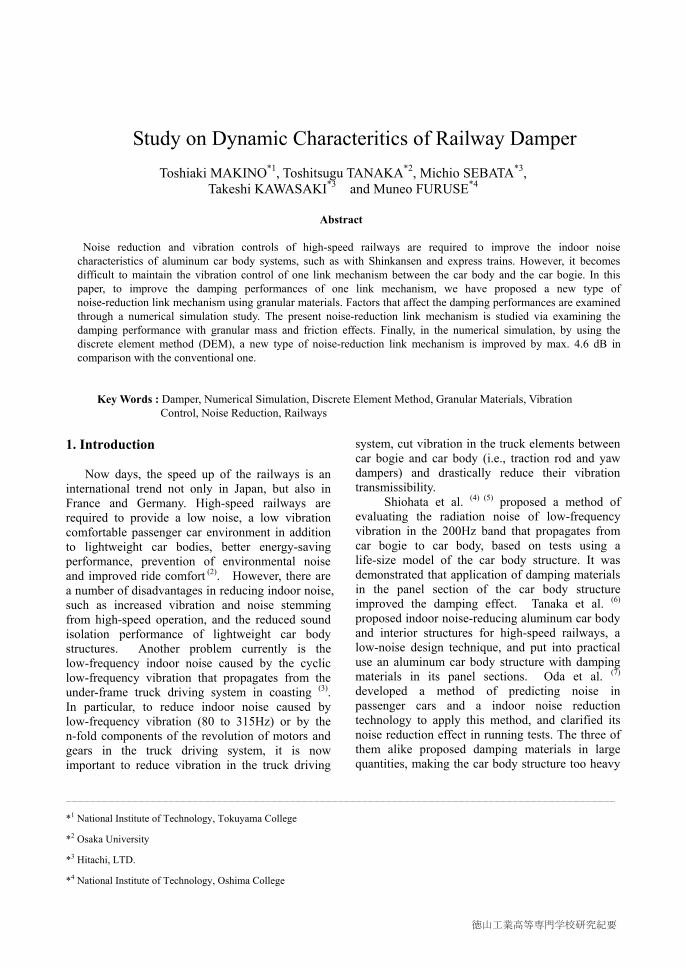
2. Composition and damping characteristics of the noise reduction link device 2.1 Composition of one link device The railway truck is composed of the bolsterless bogie shown in Fig. 1, consisting of truck frames, wheels, wheel shifts, a primary suspension system (elements connecting bearing boxes and truck frames), a secondary suspension system (air springs, left and right yaw dampers, and a traction rod connecting truck frames and car body), motors, gears, couplings and brake units. The elements connecting the car body and the truck are air springs, yaw dampers and a traction rod. There are two air springs on the truck frames to support the car body weight, and two yaw dampers (one each on the front and rear between car body and truck) to improve the stability of lateral motion. The traction rod is an element to transmit the longitudinal force from the truck to the car body. Low-frequency vibration (85 to 315Hz) caused by the fluctuation of longitudinal force propagates from the truck to the car body through the traction rod, and is emitted indoor as low-frequency noise. It is noted that the noise level is significantly higher in coasting than in powering (16).
Since the conventional traction rod transmits the longitudinal vibration of the truck directly to the car body, a damping effect can be expected only with rubber vibration isolators on both ends in the peak frequency band. To offset this drawback, the authors proposed a system whereby multiple granules are contained in the hollow space of the traction rod. This converts the truck's vibration energy into the kinetic energy of the granules, and utilizes the friction damping between the granules and between the granules and the link inner walls, thereby reducing the transmission ratio of truck vibration to the car body.
Fig.1 Configuration of railway truck
Toshiaki MAKINO, Toshitsugu TANAKA, Michio SEBATA, Takeshi KAWASAKI and Muneo FURUSE
No.38 (2014)
12
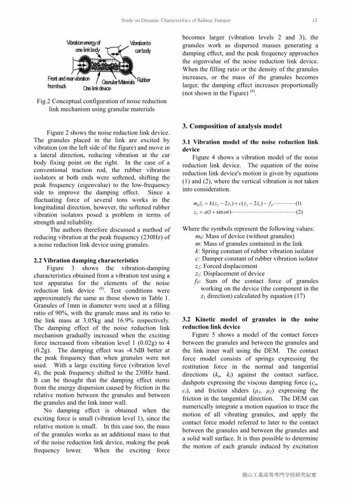
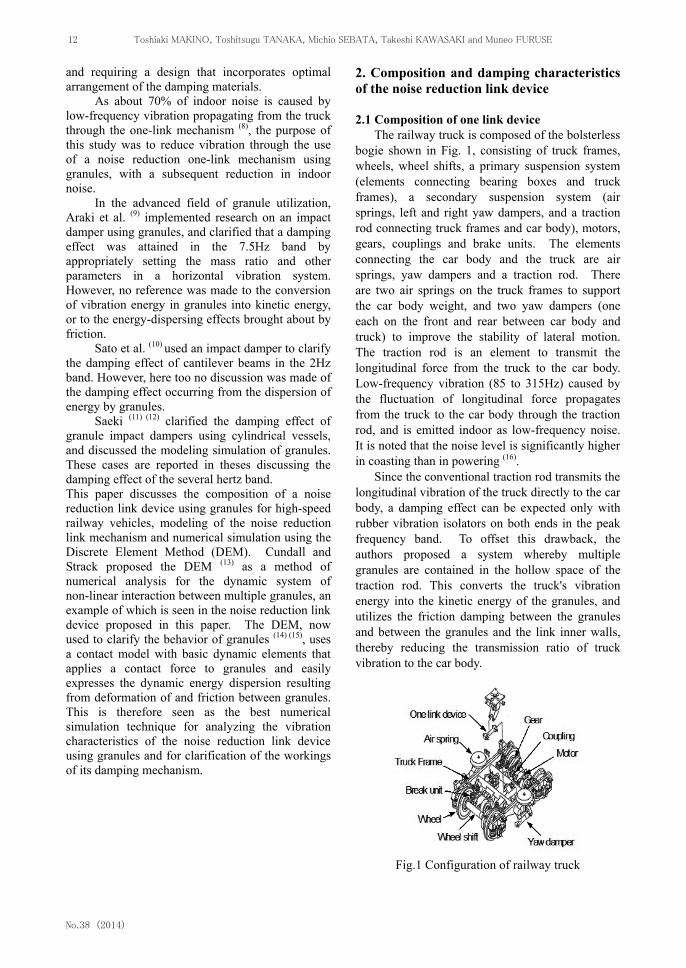
Fig.2 Conceptual configuration of noise reduction
link mechanism using granular materials
Figure 2 shows the noise reduction link device. The granules placed in the link are excited by vibration (on the left side of the figure) and move in a lateral direction, reducing vibration at the car body fixing point on the right. In the case of a conventional traction rod, the rubber vibration isolators at both ends were softened, shifting the peak frequency (eigenvalue) to the low-frequency side to improve the damping effect. Since a fluctuating force of several tons works in the longitudinal direction, however, the softened rubber vibration isolators posed a problem in terms of strength and reliability.
The authors therefore discussed a method of reducing vibration at the peak frequency (230Hz) of a noise reduction link device using granules. 2.2 Vibration damping characteristics
Figure 3 shows the vibration-damping characteristics obtained from a vibration test using a test apparatus for the elements of the noise reduction link device (8). Test conditions were approximately the same as those shown in Table 1. Granules of 1mm in diameter were used at a filling ratio of 90%, with the granule mass and its ratio to the link mass at 3.05kg and 16.9% respectively. The damping effect of the noise reduction link mechanism gradually increased when the exciting force increased from vibration level 1 (0.02g) to 4 (0.2g). The damping effect was -4.5dB better at the peak frequency than when granules were not used. With a large exciting force (vibration level 4), the peak frequency shifted to the 230Hz band. It can be thought that the damping effect stems from the energy dispersion caused by friction in the relative motion between the granules and between the granules and the link inner wall.
No damping effect is obtained when the exciting force is small (vibration level 1), since the relative motion is small. In this case too, the mass of the granules works as an additional mass to that of the noise reduction link device, making the peak frequency lower. When the exciting force
becomes larger (vibration levels 2 and 3), the granules work as dispersed masses generating a damping effect, and the peak frequency approaches the eigenvalue of the noise reduction link device. When the filling ratio or the density of the granules increases, or the mass of the granules becomes larger, the damping effect increases proportionally (not shown in the Figure) (8).
3. Composition of analysis model 3.1 Vibration model of the noise reduction link device
Figure 4 shows a vibration model of the noise reduction link device. The equation of the noise reduction link device's motion is given by equations (1) and (2), where the vertical vibration is not taken into consideration.
Where the symbols represent the following values:
m0: Mass of device (without granules) m: Mass of granules contained in the link k: Spring constant of rubber vibration isolator c: Damper constant of rubber vibration isolator z2: Forced displacement z1: Displacement of device fP: Sum of the contact force of granules
working on the device (the component in the z1 direction) calculated by equation (17)
3.2 Kinetic model of granules in the noise reduction link device
Figure 5 shows a model of the contact forces between the granules and between the granules and the link inner wall using the DEM. The contact force model consists of springs expressing the restitution force in the normal and tangential directions (kn, kt) against the contact surface, dashpots expressing the viscous damping force (cn, ct), and friction sliders (μ1, μ2) expressing the friction in the tangential direction. The DEM can numerically integrate a motion equation to trace the motion of all vibrating granules, and apply the contact force model referred to later to the contact between the granules and between the granules and a solid wall surface. It is thus possible to determine the motion of each granule induced by excitation
)2()sin1()1()2()2(
2
121210
tazfzzczzkzm P
Study on Dynamic Characteritics of Railway Damper
徳山工業高等専門学校研究紀要
13

With granular materials Vib. 1
Vib. 2
Vib. 3
Without granular materials Conventional one
Vib. 4
25
20
15
10
5 100 150 200 250 300 350
Frequency (Hz)
Vibr
ation
tran
smitta
l ratio
( dB
)
Fig. 3 Damping performances of noise reductionlink mechanism using granular materials
With granular materials Vib. 1
Vib. 2
Vib. 3
Without granular materials Conventional one
Vib. 4
25
20
15
10
5 100 150 200 250 300 350
Frequency (Hz)
Vibr
ation
tran
smitta
l ratio
( dB
)
Fig. 3 Damping performances of noise reductionlink mechanism using granular materials
Link body
m1 m2
m0z1z2
Granular Materials Spring
Damper
fp
Fig. 4 Schematic analysis model of noise reduction linkmechanism using granular materials
kk
cc
Link body
m1 m2
m0z1z2
Granular Materials Spring
Damper
fp
Fig. 4 Schematic analysis model of noise reduction linkmechanism using granular materials
kk
cc
ct
m2
Mass (j)
Tangential direction
kt
μ2Contact force (fp)
Link body Normal direction clkl
cn
kn
μ1
m1
Mass (i)
m0fp
Fig. 5 Schematic diagram of contact force model using discrete element method (DEM)
ct
m2
Mass (j)
Tangential direction
kt
μ2Contact force (fp)
Link body Normal direction clkl
cn
kn
μ1
m1
Mass (i)
m0fp
Fig. 5 Schematic diagram of contact force model using discrete element method (DEM)
and the energy dispersion subsequently caused by the deformation of the granules and the friction between them.
The motion of granules is given by equations (3) and (4). Where the symbols represent the following values:
: Center of gravity of granules m: Mass of granules
Pf : Sum of contact force g : Acceleration of gravity : Angular velocity of granule
PT
: Sum of torque due to contact force I: Moment of inertia of granules
The arrow and the dot above the symbol represent a vector and a differential with respect to time. Equations (3) and (4) are numerically integrated as explained below. When the time increment in the calculation is denoted by Δt, and the position, velocity and angular velocity of a granule at a given time are given by 0
, 0su and 0 respectively,
contact force fP and torque TP are determined. The values of 0
and 0 at that instant are derived
from equations (3) and (4). Velocity s , angular
velocity and position after time length Δt
are given by equations (5), (6) and (7) respectively. 3.3 Contact force model of granules
For the contact force model, the authors used Hertz's theoretical solution for elastic restitution force in the tangential direction, and the model given by Tanaka et al (14). that defines the viscous damping coefficient to make the restitution coefficient constant.
Restitution force Pnijf in the tangential
direction (received at the contact point by granule i from granule j) is determined as follows as the sum of spring force and viscous damping force:
Where rij is the relative velocity of granule i against granule j, and ijn is the unit vector in the normal direction from granule i to granule j. The symbol α is a dimensionless constant used as the restitution coefficient. The viscous damping force is set to make the restitution coefficient constant (14). Here, Spring constant knp between spherical granules with a radius of γP is given by equation (10):
)4(
)3(
IT
gmfr
P
P
)7(
)6(
)5(
0
0000
000
tvrr
tI
Tt
tgmfvtrvv
S
P
PSSS
)9(
)8()(41
23
nijnPn
ijijrijnnijnPPnij
kmc
nnvckf
)10()1(3
22
P
PPnp
Erk
Toshiaki MAKINO, Toshitsugu TANAKA, Michio SEBATA, Takeshi KAWASAKI and Muneo FURUSE
No.38 (2014)
14
Where EP represent σp are Young's modulus and Poisson’s ratio of the granules respectively.
For the contact between a spherical granule and the link inner wall, the restitution force in the normal direction is obtained by replacing granule j with the link inner wall, and knp with knw or equation (11):
Where EW and σW represent Young's modulus
and Poisson’s ratio of the wall respectively. The restitution force in tangential direction
Ptijf is given by equations (12) and (13).
Where δtij and sij are the relative
displacement vector and the relative surface velocity vector of granule i against granule j respectively. Spring constant kt and viscous damping coefficient Ct are determined in the manner shown in reference (14).
Equation (12) holds only when there are no slips. Here, the authors judged that a slip had occurred when the conditions in equation (14) were satisfied, and determined fptij by equation (15), where μf is the dynamic friction coefficient. Where ijt = sij / sij .
Therefore, the contact force and the torque
working on granule i are given by equations (17) and (18) as the sum of all tangential forces working on granule i.
4. Numerical calculation
4.1 Method of calculation Figures 6 and 7 show the coordinate axes and
the program chart for calculation using the analysis model in section 3.
For the movement of granules, Figure 6 sets the lateral and vertical directions as the Z- and Y-axes respectively, and the direction perpendicular to these two axes as the X-axis. The coordinates of granule position are expressed as Px(i), Py(i) and Pz(i). The left and right surface in the link to which the contact force is transmitted, and the inner wall of the link, are referred to as floor, ceiling and wall respectively. As the flow chart in Figure 7 indicates, the program repeats the steps to read the granule constants referred to later, calculate and set the initial values of granules, initialize their contact force, set a grid to judge whether contact has taken place, calculate the motion of granules, and save information on the granules in contact and the calculated data. In the calculation of granule motion, the program calculates the increment in the displacement of granules, the contact force in equation (17) and the displacement of the link device.
4.2 Conditions of calculation For the calculation, the authors adopted
spherical granules of equal diameter at a density of 11.4 x 10³kg/m3, equivalent to that of the lead granules used in another test implemented at the same time, and used values of 14.0 x 10⁹ Pa, 0.04 and 0.3 as Young's modulus, the restitution coefficient and the friction coefficient respectively. These values were obtained from tests similar to those described in reference (16) (see Table 1). The authors also used 0.39 as Poisson’s ratio and 3mm as the granule diameter (a value different from the 1-mm granules used in the tests) in order to reduce the number of granules for calculation.
)11(113
4'
22
W
W
P
PPnw EE
rk
)13()()()12(Pr
nxrnnvvvvckf
jiSrijrijSij
Sijttijiij
)16()1(
)15(
)14(
Ptijijtij
ijPnijfPtij
PnijfPtij
fk
tff
ff
)18()(
)17()(
jPtijijPi
jPtijPnijPi
fnrT
fff
Fig. 6 Schematic position layout of noise reduction linkmechanism using granular materials
Link body y-axis
x-axis (px(i),py(i),pz(i))
Granular Materials Normal direction
Tangential direction
Diameter
Length
Contact force z-axis
Gravitydirection
c
k
γp
z1z2Fig. 6 Schematic position layout of noise reduction link
mechanism using granular materials
Link body y-axis
x-axis (px(i),py(i),pz(i))
Granular Materials Normal direction
Tangential direction
Diameter
Length
Contact force z-axis
Gravitydirection
c
k
γp
z1z2
Study on Dynamic Characteritics of Railway Damper
徳山工業高等専門学校研究紀要
15
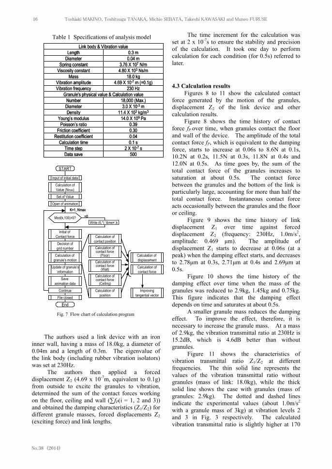
Table 1 Specifications of analysis model Link body & Vibration value
DiameterLength
Viscosity constantSpring constant
Vibration amplitudeMass
Number
Vibration frequency
Diameter
Granule's physical value & Calculation value
DensityYoung’s modulus
Poisson’s ratioFriction coefficient
Restitution coefficientCalculation time
Time stepData save
0.04 m0.3 m
4.80 X 10³ Ns/m3.76 X 107 N/m
4.69 X 10⁻⁷ m (=0.1g)18.0 kg
230 Hz
18,000 (Max.)3.0 X 10⁻³ m
11.4 X 10³ kg/m3
14.0 X 10⁹ Pa0.390.300.040.1 s
2 X 10⁻⁷ s500
The authors used a link device with an iron
inner wall, having a mass of 18.0kg, a diameter of 0.04m and a length of 0.3m. The eigenvalue of the link body (including rubber vibration isolators) was set at 230Hz.
The authors then applied a forced displacement Z2 (4.69 x 10⁻⁷m, equivalent to 0.1g) from outside to excite the granules to vibration, determined the sum of the contact forces working on the floor, ceiling and wall (∑fP(i = 1, 2 and 3)) and obtained the damping characteristics (Z1/Z2) for different granule masses, forced displacements Z2 (exciting force) and link lengths.
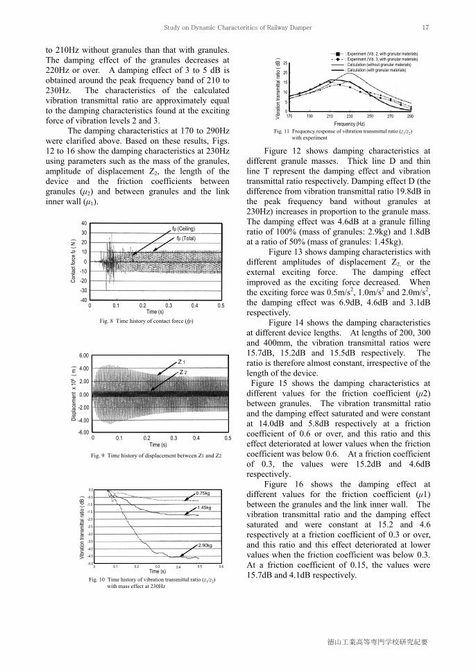
The time increment for the calculation was set at 2 x 10⁻⁷s to ensure the stability and precision of the calculation. It took one day to perform calculation for each condition (for 0.5s) referred to later.
4.3 Calculation results Figures 8 to 11 show the calculated contact
force generated by the motion of the granules, displacement Z2 of the link device and other calculation results.
Figure 8 shows the time history of contact force fP over time, when granules contact the floor and wall of the device. The amplitude of the total contact force fP, which is equivalent to the damping force, starts to increase at 0.06s to 8.6N at 0.1s, 10.2N at 0.2s, 11.5N at 0.3s, 11.8N at 0.4s and 12.0N at 0.5s. As time goes by, the sum of the total contact force of the granules increases to saturation at about 0.5s. The contact force between the granules and the bottom of the link is particularly large, accounting for more than half the total contact force. Instantaneous contact force acts occasionally between the granules and the floor or ceiling.
Figure 9 shows the time history of link displacement Z1 over time against forced displacement Z2 (frequency: 230Hz, 1.0m/s2, amplitude: 0.469 μm). The amplitude of displacement Z1 starts to decrease at 0.06s (at a peak) when the damping effect starts, and decreases to 2.78μm at 0.3s, 2.71μm at 0.4s and 2.69μm at 0.5s.
Figure 10 shows the time history of the damping effect over time when the mass of the granules was reduced to 2.9kg, 1.45kg and 0.75kg. This figure indicates that the damping effect depends on time and saturates at about 0.5s.
A smaller granule mass reduces the damping effect. To improve the effect, therefore, it is necessary to increase the granule mass. At a mass of 2.9kg, the vibration transmittal ratio at 230Hz is 15.2dB, which is 4.6dB better than without granules.
Figure 11 shows the characteristics of vibration transmittal ratio Z1/Z2 at different frequencies. The thin solid line represents the values of the vibration transmittal ratio without granules (mass of link: 18.0kg), while the thick solid line shows the case with granules (mass of granules: 2.9kg). The dotted and dashed lines indicate the experimental values (about 1.0m/s2 with a granule mass of 3kg) at vibration levels 2 and 3 in Fig. 3 respectively. The calculated vibration transmittal ratio is slightly higher at 170
START
Input of initial data
Calculation ofValue (Nmax)
Set of Value
Open of animation
Initial of Contact force
Decision ofgrid number
Calculation of granule's motion
Update of granule’sinformation
Save animation data
Calculation ofposition
Calculation of displacement
Calculation ofcontact force
Improvingtangential vector
Calculation ofcontact force
(Ceiling)
Calculation ofcontact force
(Wall)
Calculation ofcontact force
(Floor)
Calculation ofcontact position
File closed
Continue
End
Mod(k,100)=0?
K=1, Nmax=0
Fig. 7 Flow chart of calculation program
Write (6,*) ‘itime=’,k
START
Input of initial dataInput of initial data
Calculation ofValue (Nmax)Calculation ofValue (Nmax)
Set of ValueSet of Value
Open of animationOpen of animation
Initial of Contact force
Initial of Contact force
Decision ofgrid numberDecision ofgrid number
Calculation of granule's motionCalculation of
granule's motion
Update of granule’sinformation
Update of granule’sinformation
Save animation data
Save animation data
Calculation ofposition
Calculation ofposition
Calculation of displacementCalculation of displacement
Calculation ofcontact forceCalculation ofcontact force
Improvingtangential vector
Improvingtangential vector
Calculation ofcontact force
(Ceiling)
Calculation ofcontact force
(Ceiling)
Calculation ofcontact force
(Wall)
Calculation ofcontact force
(Wall)
Calculation ofcontact force
(Floor)
Calculation ofcontact force
(Floor)
Calculation ofcontact positionCalculation of
contact position
File closedFile closed
Continue
End
Mod(k,100)=0?
K=1, Nmax=0
Fig. 7 Flow chart of calculation program
Write (6,*) ‘itime=’,k
Toshiaki MAKINO, Toshitsugu TANAKA, Michio SEBATA, Takeshi KAWASAKI and Muneo FURUSE
No.38 (2014)
16
0.30.20.1 0.4 0.50
40
0
-30-20
20
-10
10
30
-40
Conta
ct for
ce fp
( N )
Time (s) Fig. 8 Time history of contact force (fp)
fp (Total) fp (Ceiling)
0.30.20.1 0.4 0.50
40
0
-30-20
20
-10
10
30
-40
Conta
ct for
ce fp
( N )
Time (s) Fig. 8 Time history of contact force (fp)
fp (Total) fp (Ceiling)
2.00
-4.00
-2.00
6.00
0.00
4.00
-6.00
Disp
lacem
ent x
106
( m )
Fig. 9 Time history of displacement between Z1 and Z2
0.30.20.1 0.40 Time (s)
Z 2
Z 1
0.5
2.00
-4.00
-2.00
6.00
0.00
4.00
-6.00
Disp
lacem
ent x
106
( m )
Fig. 9 Time history of displacement between Z1 and Z2
0.30.20.1 0.40 Time (s)
Z 2
Z 1
0.5
15
5
25
10
20
0
Vibr
ation
tran
smitta
l ratio
( dB
)
Frequency (Hz) 170
Fig. 11 Frequency response of vibration transmittal ratio (z1/z2) with experiment
230210190 290270250
: Experiment (Vib. 2, with granular materials): Experiment (Vib. 3, with granular materials): Calculation (without granular materials): Calculation (with granular materials)
to 210Hz without granules than that with granules. The damping effect of the granules decreases at 220Hz or over. A damping effect of 3 to 5 dB is obtained around the peak frequency band of 210 to 230Hz. The characteristics of the calculated vibration transmittal ratio are approximately equal to the damping characteristics found at the exciting force of vibration levels 2 and 3.
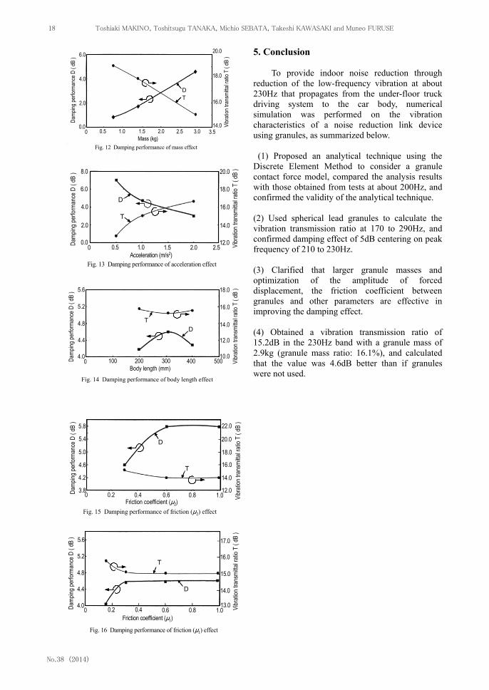
The damping characteristics at 170 to 290Hz were clarified above. Based on these results, Figs. 12 to 16 show the damping characteristics at 230Hz using parameters such as the mass of the granules, amplitude of displacement Z2, the length of the device and the friction coefficients between granules (μ2) and between granules and the link inner wall (μ1).
Figure 12 shows damping characteristics at different granule masses. Thick line D and thin line T represent the damping effect and vibration transmittal ratio respectively. Damping effect D (the difference from vibration transmittal ratio 19.8dB in the peak frequency band without granules at 230Hz) increases in proportion to the granule mass. The damping effect was 4.6dB at a granule filling ratio of 100% (mass of granules: 2.9kg) and 1.8dB at a ratio of 50% (mass of granules: 1.45kg).
Figure 13 shows damping characteristics with different amplitudes of displacement Z2, or the external exciting force. The damping effect improved as the exciting force decreased. When the exciting force was 0.5m/s2, 1.0m/s2 and 2.0m/s2, the damping effect was 6.9dB, 4.6dB and 3.1dB respectively.
Figure 14 shows the damping characteristics at different device lengths. At lengths of 200, 300 and 400mm, the vibration transmittal ratios were 15.7dB, 15.2dB and 15.5dB respectively. The ratio is therefore almost constant, irrespective of the length of the device. Figure 15 shows the damping characteristics at different values for the friction coefficient (μ2) between granules. The vibration transmittal ratio and the damping effect saturated and were constant at 14.0dB and 5.8dB respectively at a friction coefficient of 0.6 or over, and this ratio and this effect deteriorated at lower values when the friction coefficient was below 0.6. At a friction coefficient of 0.3, the values were 15.2dB and 4.6dB respectively.
Figure 16 shows the damping effect at different values for the friction coefficient (μ1) between the granules and the link inner wall. The vibration transmittal ratio and the damping effect saturated and were constant at 15.2 and 4.6 respectively at a friction coefficient of 0.3 or over, and this ratio and this effect deteriorated at lower values when the friction coefficient was below 0.3. At a friction coefficient of 0.15, the values were 15.7dB and 4.1dB respectively.
-1.0
-4.0
-2.0
0.0
-1.5
-0.5
-5.0
Vibr
ation
tran
smitta
l ratio
( dB
) 0.75kg
-4.5
-3.5
-3.0
-2.5
Time (s) 0 0.1 0.2 0.3 0.4 0.5 0.6
Fig. 10 Time history of vibration transmittal ratio (z1/z2) with mass effect at 230Hz
1.45kg
2.90kg
-1.0
-4.0
-2.0
0.0
-1.5
-0.5
-5.0
Vibr
ation
tran
smitta
l ratio
( dB
) 0.75kg
-4.5
-3.5
-3.0
-2.5
Time (s) 0 0.1 0.2 0.3 0.4 0.5 0.6
Fig. 10 Time history of vibration transmittal ratio (z1/z2) with mass effect at 230Hz
1.45kg
2.90kg
Study on Dynamic Characteritics of Railway Damper
徳山工業高等専門学校研究紀要
17
2.0
0.0
6.0
4.0Da
mping
perfo
rman
ce D
( dB
)
Fig. 12 Damping performance of mass effect
1.51.00.5 2.0 2.5Mass (kg)
DT
0
Vibr
ation
tran
smitta
l ratio
T (
dB )
16.0
20.0
14.0
18.0
3.0 3.5
2.0
0.0
6.0
4.0Da
mping
perfo
rman
ce D
( dB
)
Fig. 12 Damping performance of mass effect
1.51.00.5 2.0 2.5Mass (kg)
DT
0
Vibr
ation
tran
smitta
l ratio
T (
dB )
16.0
20.0
14.0
18.0
3.0 3.5
2.0
0.0
6.0
4.0Da
mping
perfo
rman
ce D
( dB
)
Fig. 12 Damping performance of mass effect
1.51.00.5 2.0 2.5Mass (kg)
DT
0
Vibr
ation
tran
smitta
l ratio
T (
dB )
16.0
20.0
14.0
18.0
3.0 3.5
4.0
0.0
8.0
2.0
6.0
Damp
ing pe
rform
ance
D (
dB )
Fig. 13 Damping performance of acceleration effect
1.51.00.5 2.0 2.5Acceleration (m/s2)
D
T
0 Vibr
ation
tran
smitta
l ratio
T (
dB )
16.0
12.0
20.0
14.0
18.0
4.0
0.0
8.0
2.0
6.0
Damp
ing pe
rform
ance
D (
dB )
Fig. 13 Damping performance of acceleration effect
1.51.00.5 2.0 2.5Acceleration (m/s2)
D
T
0 Vibr
ation
tran
smitta
l ratio
T (
dB )
16.0
12.0
20.0
14.0
18.0
4.8
4.4
5.6
5.2
Damp
ing pe
rform
ance
D (
dB )
Fig. 14 Damping performance of body length effect
200100 300 400Body length (mm)
0 Vibr
ation
tran
smitta
l ratio
T (
dB )
12.0
18.0
14.0
16.0
5004.0 10.0
DT4.8
4.4
5.6
5.2
Damp
ing pe
rform
ance
D (
dB )
Fig. 14 Damping performance of body length effect
200100 300 400Body length (mm)
0 Vibr
ation
tran
smitta
l ratio
T (
dB )
12.0
18.0
14.0
16.0
5004.0 10.0
DT
5.0
4.6
5.8
5.4
Damp
ing pe
rform
ance
D (
dB )
Fig. 15 Damping performance of friction (μ2) effect
0.40.2 0.6 0.8Friction coefficient (μ2)
0 Vibr
ation
tran
smitta
l ratio
T (
dB )
16.0
22.0
18.0
20.0
1.03.8 12.0
D
T4.2 14.0
5.0
4.6
5.8
5.4
Damp
ing pe
rform
ance
D (
dB )
Fig. 15 Damping performance of friction (μ2) effect
0.40.2 0.6 0.8Friction coefficient (μ2)
0 Vibr
ation
tran
smitta
l ratio
T (
dB )
16.0
22.0
18.0
20.0
1.03.8 12.0
D
T4.2 14.0
4.8
4.0
5.6
5.2
Damp
ing pe
rform
ance
D (
dB )
Fig. 16 Damping performance of friction (μ1) effect
0.40.2 0.6 0.8Friction coefficient (μ1)
D
T
0 Vibr
ation
tran
smitta
l ratio
T (
dB )
15.0
17.0
14.0
16.0
1.0
4.4
13.0
4.8
4.0
5.6
5.2
Damp
ing pe
rform
ance
D (
dB )
Fig. 16 Damping performance of friction (μ1) effect
0.40.2 0.6 0.8Friction coefficient (μ1)
D
T
0 Vibr
ation
tran
smitta
l ratio
T (
dB )
15.0
17.0
14.0
16.0
1.0
4.4
13.0
5. Conclusion
To provide indoor noise reduction through reduction of the low-frequency vibration at about 230Hz that propagates from the under-floor truck driving system to the car body, numerical simulation was performed on the vibration characteristics of a noise reduction link device using granules, as summarized below.
(1) Proposed an analytical technique using the Discrete Element Method to consider a granule contact force model, compared the analysis results with those obtained from tests at about 200Hz, and confirmed the validity of the analytical technique. (2) Used spherical lead granules to calculate the vibration transmission ratio at 170 to 290Hz, and confirmed damping effect of 5dB centering on peak frequency of 210 to 230Hz. (3) Clarified that larger granule masses and optimization of the amplitude of forced displacement, the friction coefficient between granules and other parameters are effective in improving the damping effect. (4) Obtained a vibration transmission ratio of 15.2dB in the 230Hz band with a granule mass of 2.9kg (granule mass ratio: 16.1%), and calculated that the value was 4.6dB better than if granules were not used.
Toshiaki MAKINO, Toshitsugu TANAKA, Michio SEBATA, Takeshi KAWASAKI and Muneo FURUSE
No.38 (2014)
18
References (1) Ohyama, T., Research and Development for
Reducting Noise and Vibration in Shinkansen, RTRI Report, Vol.8, No.6 (1994), p.1-7(in Japanese)
(2) Yoshikawa, T., Development of High-Speed
Railway, Machine Research, Vol.46, No.10 (1994), p.1020-1026(in Japanese)
(3) Suzuki, H., Study on Analytical Method for
Vibration of Railway Vehicle and its Damping Method, RTRI Report, Special No.16 (1997), p.1-138(in Japanese)
(4) Shiohata, H., Study of Active Noise Control by
using Structural Acoustic Coupled, Proc. JSME D&D Symp. ,No.5 (1997), p.1-6(in Japanese)
(5) Shiohata, H., Nemoto, K., Iwatsubo,T., Vibration
and Acoustic Sensitivity Analysis, Trans. Jpn.Soc.Mech.Eng., Vol.54 No.505, C (1998), p.125-134 (in Japanese)
(6) Tanaka, T., Noise Control in Aluminum Car Body
of High-Speed Train by using Damping Material, Noise Control, Vol.22, No.4 (1998), p.90-98(in Japanese)
(7) Oda, M., Noise Reduction in Aluminum Car Body,
Kawasaki Heavy Company Report No.138 (1998), p.70-77(in Japanese)
(8) Sebata, M., Makino, T., Development of Noise
Reduction Link Mechanism using Granular Materials, Proc. of JSME Symp. , 3-JA-13 (2003), p.65-70(in Japanese)
(9) Yokomichi, I., Araki, Y., Impact Dampers with
Granular Materials for Multibody System, Trans. of ASME J, Presuur Vessel Technolgy, Vol.118(1996), p.95-103(in Japanese)
(10) Sato, T., Makino, T., Vibration on Reduction of an
Impact Damper, Trans. Proc, Asia-Pacific Vibration Conf. ’2010 , p.963-968 (2010)
(11) Saeki, M., Analysis of Impact Damper with
Granular Materials, Trans. of JSME, Ser.C, Vol.68, No.673(2002), p.2585-2591(in Japanese)
(12) Saeki, M., Trans. of JSME (in Japanese), Ser.C,
Vol.68, No.673 (2002), p.2585 (13) Cundall, P. A. and Strack, O. D. L., Geotechnique,
Vol.29, No.1 (1979), p.47 (14) Tanaka, T., Ishida, T. and Tsuji, Y., Trans. of JSME
(in Japanese), Ser.B, Vol.57, No.534 (1991), p.456 (15) Kawaguchi, T., Tsuji, Y., and Tanaka, T., Trans. of
JSME (in Japanese), Ser.B, Vol.58, No.551 (1992), p.2119
(16) Sebata, M., Makino, T., Running Test on Noise Reduction Link Mechanism for High Speed Railways, Proc. of J-RAIL’02 Symp. ,S3-2-2 (2001) p.203-206(in Japanese)
(Received August 29, 2014)
Study on Dynamic Characteritics of Railway Damper
徳山工業高等専門学校研究紀要
19


![ACATacat.or.th/download/acat_or_th/journal-4/04 - 04.pdf · APmin APmax Appendix G [1] AP APmax Overpressure Relief Damper Damper 12 Relief Damper Relief Damper (Vent) Fire Damper](https://static.fdocuments.in/doc/165x107/5f7cb481641db55595223717/-04pdf-apmin-apmax-appendix-g-1-ap-apmax-overpressure-relief-damper-damper.jpg)
