Study on Dynamic Characteristics of Wind Farm with ...
4
Study on Dynamic Characteristics of Wind Farm with Different Wind Turbine Types Chia-Yu HSU 1, a , Ta-Hsiu TSENG 2, b , Yun-Sheng JHAN 3, c , Pei-Hwa HUANG 4, d 1,2,3,4 Department of Electrical Engineering, National Taiwan Ocean University, Keelung, 20224 Taiwan a [email protected], b [email protected], C [email protected], d [email protected]. tw Keywords: Wind Farm, Doubly Fed Induction Generator, Full Converter Wind Turbine, Transient Response Abstract. With more penetration of wind energy from onshore and offshore wind farms, wind generation will thus be exerting more influences on the original power system. The main purpose of this paper is to study two commonly adopted offshore wind turbine types, namely the doubly-fed induction generator and the full converter wind turbine. These two types of wind turbines are to be set as the offshore wind farm generating machines to compare their performances in the system. Transient responses of the two kinds of wind turbines under three-phase fault are analyzed to verify their ride-through capabilities. Results show that, that the wind farm with the doubly-fed induction generator has a better performance than full converter wind turbine during and after fault, and full converter wind turbine is capable of providing more reactive power as compared to the doubly-fed induction generator. Introduction Wind energy as an alternative to fossil fuels, renewable, widely distributed, clean, produces no greenhouse gas emissions during operation. The effects on the environment are far less problematic than those of fossil fuels [1]. The latest technological advancements in wind energy conversion and the increased support from government and private institutions have led to increased wind turbine generator in recent years [2]. With more generation from the onshore and offshore wind farms and thus increase in proportion from wind farms in the total system generation, the wind turbines exert more influences on the system and the regulation of parallel operation for the wind turbines has been becoming more and more stringent [3]. One of these influences is the analysis and advances of grid rules or technical code requirements regarding the improvement of dynamic support to the grid, and ride-through capabilities of wind turbines [4]. Therefore, the interaction with the power grid has become a major issue for wind turbines. In this paper, the doubly-fed induction generators and the full converter wind turbines have been adopted respectively in the offshore wind farm to compare their performances on the wind power integrated system. Wind Turbines The Western Electricity Coordinating Council (WECC) Modeling and Validation Working Group recently initiated an effort to develop and validate a series of generic dynamic models for wind turbine generators (WTG) [5]. Wind turbine generators have been classified into four basic types: (a) Type A: Squirrel Cage Induction Generator (b) Type B: Wound Rotor Induction Generator (c) Type C: Doubly-Fed Induction Generator (DFIG) (d) Type D: Full-converter Generator [6] [7]. Type C: The DFIG is common variable speed topology which utilizes wound-rotor induction machines with an AC/DC/AC converter between the stator and rotor terminals, is shown in Figure 1. The AC/DC/AC converter is divided into two parts, rotor side and grid side. The rotor is fed by the rotor side power converter and the grid side power converter is used to generate or absorb power in order to keep the DC link voltage constant. The generator stator winding is directly coupled to the 3rd International Conference on Machinery, Materials and Information Technology Applications (ICMMITA 2015) © 2015. The authors - Published by Atlantis Press 408
Transcript of Study on Dynamic Characteristics of Wind Farm with ...

Study on Dynamic Characteristics of Wind Farm with Different Wind Turbine Types
Chia-Yu HSU1, a, Ta-Hsiu TSENG2, b, Yun-Sheng JHAN3, c, Pei-Hwa HUANG4, d 1,2,3,4 Department of Electrical Engineering, National Taiwan Ocean University, Keelung, 20224
Taiwan [email protected], [email protected], [email protected], [email protected].
tw
Keywords: Wind Farm, Doubly Fed Induction Generator, Full Converter Wind Turbine, Transient Response
Abstract. With more penetration of wind energy from onshore and offshore wind farms, wind generation will thus be exerting more influences on the original power system. The main purpose of this paper is to study two commonly adopted offshore wind turbine types, namely the doubly-fed induction generator and the full converter wind turbine. These two types of wind turbines are to be set as the offshore wind farm generating machines to compare their performances in the system. Transient responses of the two kinds of wind turbines under three-phase fault are analyzed to verify their ride-through capabilities. Results show that, that the wind farm with the doubly-fed induction generator has a better performance than full converter wind turbine during and after fault, and full converter wind turbine is capable of providing more reactive power as compared to the doubly-fed induction generator.
Introduction Wind energy as an alternative to fossil fuels, renewable, widely distributed, clean, produces no
greenhouse gas emissions during operation. The effects on the environment are far less problematic than those of fossil fuels [1]. The latest technological advancements in wind energy conversion and the increased support from government and private institutions have led to increased wind turbine generator in recent years [2]. With more generation from the onshore and offshore wind farms and thus increase in proportion from wind farms in the total system generation, the wind turbines exert more influences on the system and the regulation of parallel operation for the wind turbines has been becoming more and more stringent [3]. One of these influences is the analysis and advances of grid rules or technical code requirements regarding the improvement of dynamic support to the grid, and ride-through capabilities of wind turbines [4]. Therefore, the interaction with the power grid has become a major issue for wind turbines. In this paper, the doubly-fed induction generators and the full converter wind turbines have been adopted respectively in the offshore wind farm to compare their performances on the wind power integrated system.
Wind Turbines The Western Electricity Coordinating Council (WECC) Modeling and Validation Working Group
recently initiated an effort to develop and validate a series of generic dynamic models for wind turbine generators (WTG) [5]. Wind turbine generators have been classified into four basic types: (a) Type A: Squirrel Cage Induction Generator (b) Type B: Wound Rotor Induction Generator (c) Type C: Doubly-Fed Induction Generator (DFIG) (d) Type D: Full-converter Generator [6] [7].
Type C: The DFIG is common variable speed topology which utilizes wound-rotor induction machines with an AC/DC/AC converter between the stator and rotor terminals, is shown in Figure 1. The AC/DC/AC converter is divided into two parts, rotor side and grid side. The rotor is fed by the rotor side power converter and the grid side power converter is used to generate or absorb power in order to keep the DC link voltage constant. The generator stator winding is directly coupled to the
3rd International Conference on Machinery, Materials and Information Technology Applications (ICMMITA 2015)
© 2015. The authors - Published by Atlantis Press 408
grid. Generation of power at variable speeds ranging from below synchronous speed to above synchronous speed can be achieved using DFIG.
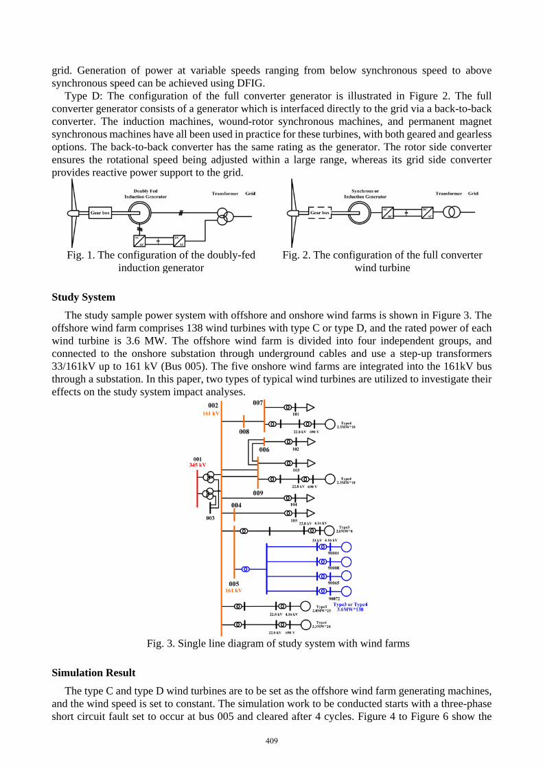
Type D: The configuration of the full converter generator is illustrated in Figure 2. The full converter generator consists of a generator which is interfaced directly to the grid via a back-to-back converter. The induction machines, wound-rotor synchronous machines, and permanent magnet synchronous machines have all been used in practice for these turbines, with both geared and gearless options. The back-to-back converter has the same rating as the generator. The rotor side converter ensures the rotational speed being adjusted within a large range, whereas its grid side converter provides reactive power support to the grid.
Fig. 1. The configuration of the doubly-fed
induction generator Fig. 2. The configuration of the full converter
wind turbine
Study System The study sample power system with offshore and onshore wind farms is shown in Figure 3. The
offshore wind farm comprises 138 wind turbines with type C or type D, and the rated power of each wind turbine is 3.6 MW. The offshore wind farm is divided into four independent groups, and connected to the onshore substation through underground cables and use a step-up transformers 33/161kV up to 161 kV (Bus 005). The five onshore wind farms are integrated into the 161kV bus through a substation. In this paper, two types of typical wind turbines are utilized to investigate their effects on the study system impact analyses.
Fig. 3. Single line diagram of study system with wind farms
Simulation Result The type C and type D wind turbines are to be set as the offshore wind farm generating machines,
and the wind speed is set to constant. The simulation work to be conducted starts with a three-phase short circuit fault set to occur at bus 005 and cleared after 4 cycles. Figure 4 to Figure 6 show the
409
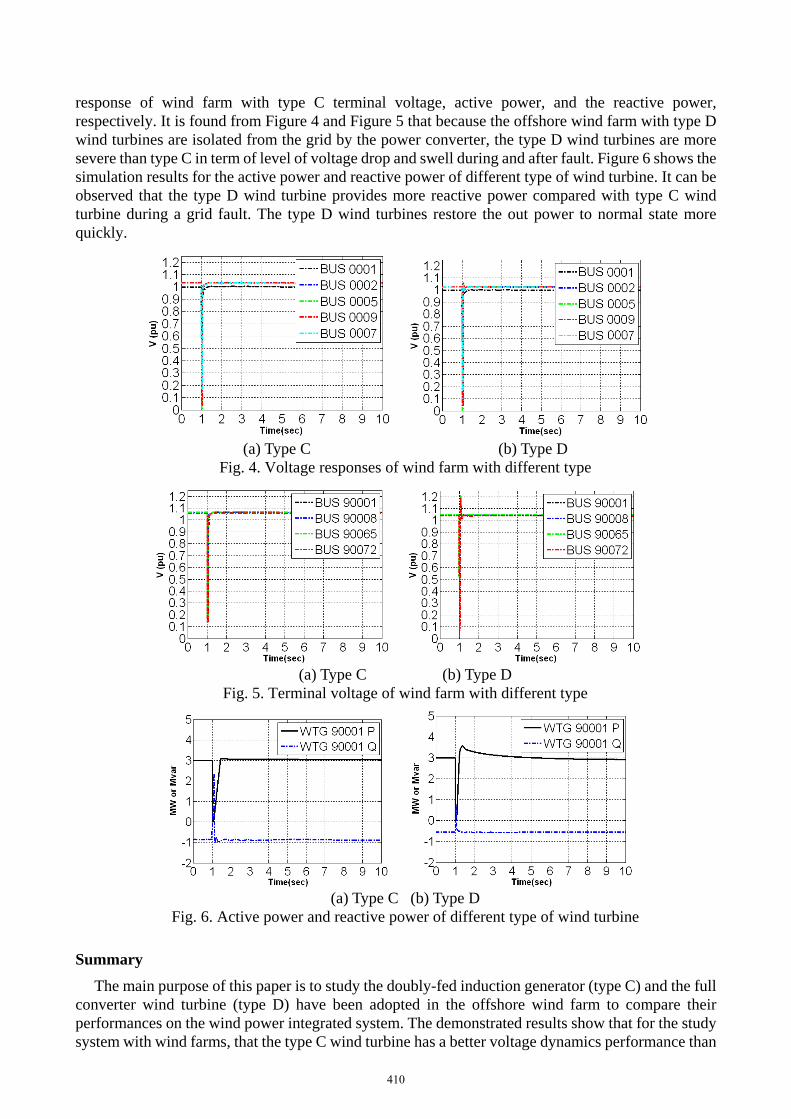
response of wind farm with type C terminal voltage, active power, and the reactive power, respectively. It is found from Figure 4 and Figure 5 that because the offshore wind farm with type D wind turbines are isolated from the grid by the power converter, the type D wind turbines are more severe than type C in term of level of voltage drop and swell during and after fault. Figure 6 shows the simulation results for the active power and reactive power of different type of wind turbine. It can be observed that the type D wind turbine provides more reactive power compared with type C wind turbine during a grid fault. The type D wind turbines restore the out power to normal state more quickly.
(a) Type C (b) Type D
Fig. 4. Voltage responses of wind farm with different type
(a) Type C (b) Type D
Fig. 5. Terminal voltage of wind farm with different type
(a) Type C (b) Type D
Fig. 6. Active power and reactive power of different type of wind turbine
Summary The main purpose of this paper is to study the doubly-fed induction generator (type C) and the full
converter wind turbine (type D) have been adopted in the offshore wind farm to compare their performances on the wind power integrated system. The demonstrated results show that for the study system with wind farms, that the type C wind turbine has a better voltage dynamics performance than
410

type D wind turbine during and after fault. The type C and type D wind turbines are equipped with power converters, but type D wind turbine can provide reactive power more than type C wind turbine, so that the full converter wind turbine can return to a steady state within a shorter time.
Acknowledgements This work was supported in part by Ministry of Science and Technology under Grants MOST
104-3113-E-194-003 and MOST 104-2221-E-019-025.
References
[1] James F. Manwell, Jon G. McGowan, Anthony L. Rogers. Wind Energy Explained: Theory, Design and Application. Wiley, 2009.
[2] Siegfried Heier. Grid Integration of Wind Energy Conversion Systems. Wiley, 2006.
[3] Lasantha Meegahapola and Damian Flynn. Impact on transient and frequency stability for a power system at very high wind penetration. Proceedings 2010 IEEE Power and Energy Society General Meeting, 2010 1-8.
[4] Yuan-Kang Wu, Ching-Yin Lee, and Ging-He Shu. Taiwan's first large-scale offshore wind farm connection-a real project case study with a comparison of wind turbine. IEEE Transactions on Industry Applications, 2011, 47( 3) 1461-1469.
[5] WECC Renewable Energy Modeling Task Force. WECC Wind Power Plant Dynamic Modeling Guide. 2010.
[6] Olimpo Anaya-Lara, Nick Jenkins, Janaka Ekanayake, Phill Cartwright, and Mike Hughes. Wind Energy Generation: Modeling and Control. Wiley, 2009.
[7] Siemens Power Technology International. PSS/E Program Operation Manual. 2009.
411