Study on Coexistence of LAA and WiFi - ECE/CIScimini/memo/2015/Cisco... · Study on Coexistence of...
22
Study on Coexistence of LAA and WiFi Cisco Cooperative Project Students: Li Li Advisors: Len Cimini , Chien - Chung Shen Sept . 17, 2015
Transcript of Study on Coexistence of LAA and WiFi - ECE/CIScimini/memo/2015/Cisco... · Study on Coexistence of...

Study on Coexistence of
LAA and WiFi
Cisco Cooperative Project
Students: Li Li
Advisors: Len Cimini, Chien-Chung Shen
Sept. 17, 2015

1
Outline
Review Simulation
Multi-carrier LBT
Power sharing for Multi-carrier LBT
Next steps

2
Review Simulation: CSMA/CA
Random backoff for initial transmission? In general, NO. [1]
For a STA to transmit, if the medium is not determined to be busy, the transmission may
proceed. A transmitting STA shall verify that the medium is idle for a required duration
before attempting to transmit. If the medium is determined to be busy, the STA shall defer
until the end of the current transmission. After deferral, or prior to attempting to transmit
again immediately after a successful transmission, the STA shall select a random backoff
interval. (Section 9.2.2)
In general, a STA may transmit a pending MPDU when it is operating under the DCF
access method, when the STA determines that the medium is idle for greater than or equal
to a DIFS period, or an EIFS period if the immediately preceding medium-busy event was
caused by detection of a frame that was not received at this STA with a correct MAC FCS
value. If, under these conditions, the medium is determined by the CS mechanism to be
busy, the random backoff procedure shall be followed. There are conditions, specified in
9.3.4.3 and 9.3.4.5, where the random backoff procedure shall be followed even for the
first attempt to initiate a frame exchange sequence. (Section 9.3.4.2)
[1] IEEE Std 802.11TM -2012, “Part 11: Wireless LAN Medium Access Control (MAC) and Physical
Layer (PHY) Specifications.”

3
Review Simulation: CSMA/CA
Contention window size [1]
DS PHY (802.11b): aCWmin = 31, aCWmax = 1023 (Table 16-2)
OFDM PHY: aCWmin = 15, aCWmax = 1024 (Table 18-17)
Enhanced distributed channel access (EDCA) (Table 8-106 in [1] and [2])
[1] IEEE Std 802.11TM -2012, “Part 11: Wireless LAN Medium Access Control (MAC) and Physical
Layer (PHY) Specifications.”
[2] https://en.wikipedia.org/wiki/IEEE_802.11e-2005

4
Review Simulation: CSMA/CA
Contention window size
Voice: Giving voice packets the highest priority enables concurrent Voice over
IP (VoIP) calls with minimal latency and the highest quality possible.
Video: By placing video packets in the second tier, WMM prioritizes it over all
other data traffic and enables support for three to four standard definition TV
(SDTV) streams or one high definition TV (HDTV) stream on a WLAN.
Best effort: Best effort data packets consist of those originating from legacy
devices or from applications or devices that lack QoS standards.
Background: Background priority encompasses file downloads, print jobs and
other traffic that does not suffer from increased latency.
In simulation, FTP traffic model :15-1023, VoIP: 3-7?
5
Review Simulation: Results
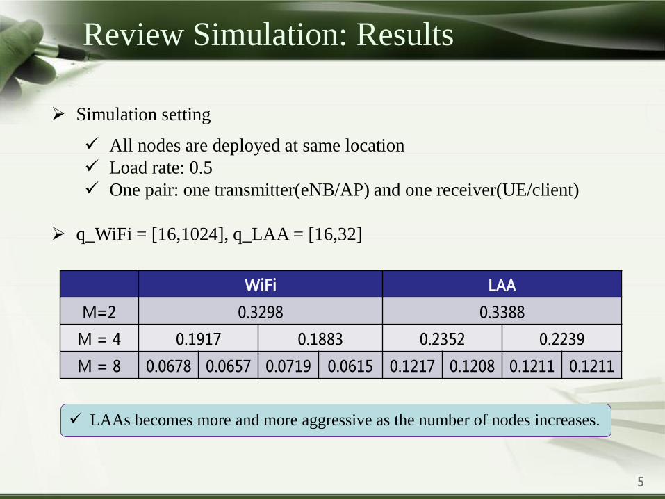
Simulation setting
All nodes are deployed at same location
Load rate: 0.5
One pair: one transmitter(eNB/AP) and one receiver(UE/client)
q_WiFi = [16,1024], q_LAA = [16,32]
WiFi LAA
M=2 0.3298 0.3388
M = 4 0.1917 0.1883 0.2352 0.2239
M = 8 0.0678 0.0657 0.0719 0.0615 0.1217 0.1208 0.1211 0.1211
LAAs becomes more and more aggressive as the number of nodes increases.

6
Review Simulation: Results
q_WiFi = [16,1024], q_LAA = 32
q_WiFi = [4,8], q_LAA = [4,8]
WiFi LAA
M=2 0.3332 0.3308
M = 4 0.2600 0.2609 0.1673 0.1725
M = 8 0.1050 0.0951 0.0959 0.1019 0.0918 0.0953 0.0954 0.0946
WiFi LAA
M=2 0.3333 0.3337
M = 4 0.1371 0.1345 0.1354 0.1362
M = 8 0.0345 0.0332 0.0360 0.0337 0.0352 0.0354 0.0347 0.0339
WiFi performs better in this case.
High collision probability, leading to ineffective transmission.
7
Review Simulation: Discussion
To better coexist with WiFi, LAA needs to change q according to the traffic
of WiFi?

8
Review Simulation: Different Locations
Simulation setting
Single floor building, 4 APs (green) and 4 eNBs (yellow) are equally
spaced [1]
Transmit power: 18 dBm
Load rate: 0.2/0.5/0.8
WiFi: CCACS = -82 dBm, CCAED = -62 dBm; LAA: CCAED = -62/-
68 dBm
q_WiFi = [4,32], q_LAA = [4,32]
[1] 3GPP TR 36.889 V13.0.0 (2015-06).

9
Review Simulation: Different Locations
Simulation results for different load rates (LAA CCAED: -68 dBm)
WiFi LAA
R = 0.2 0.1663 0.1669 0.1659 0.1663 0.1665 0.1671 0.1670 0.1662
R = 0.5 0.3012 0.1232 0.1840 0.2768 0.3188 0.3315 0.3201 0.3343
R = 0.8 0.3606 0.1111 0.1841 0.3310 0.3838 0.3833 0.3709 0.4155
The performance is better than the case of same location
For WiFi, the nodes in the margin have more opportunities to access
the channel than the nodes in the middle
For LAA, there is only competition from the closest neighbor (AP) at
most of time.

10
Review Simulation: Different locations
All WiFi
WiFi WiFi
R = 0.5 0.3236 0.2651 0.2442 0.3090 0.3044 0.2644 0.2274 0.3021
In this simulation setting, LAA has a negative impact on the performance
of WiFi.

11
Review Simulation: Discussion
All LAA eNBs will be assisted by LTE licensed part. So, with ideal
scheduling, there will be no competition among LAA eNBs?

12
Multi-carrier LBT
802.11ac’s channel bonding
The backoff procedure is only performed on the primary channel, secondary
channel(s) perform a one-shot CCA.
Only certain channel bonding configurations are allowed.
The designated primary channel should always be part of the channel bonding
configurations.

13
Multi-carrier LBT: Option 1
Currently LTE is limited to aggregate a maximum of five component carriers.
Option 1 (Extended LAA single channel LBT schemes): allow simultaneous
transmission on more than one carrier if all of those carriers have completed a full
random backoff and are idle at transmission time. (Intel/Huawei/Qualcomm)
The performance depends on the duration of the self-deferral: 1) too short, cannot get
large bandwidth; 2) too long, ineffective and may lose the transmission probability.
Once an LBT scheme for a single carrier has been specified, it can be used for LAA
multi-channel access simply by meeting the LBT requirements for each channel.

14
Multi-carrier LBT: Option 2
Option 2 (Wi-Fi like multi-channel LBT schemes): allow simultaneous transmission
on more than one carrier if one of those carriers has completed a full-fledged random
backoff and others are found to be idle before transmission for at least the duration
of 25 us. (Alcatel-Lucent, Ericsson)
Additionally configuring a “primary channel” on unlicensed spectrum for LAA
like 802.11ac may result in the transmitter failing to access other carriers when
the “primary channel” is blocked.
The LAA device can also dynamically perform independently eCCA procedure
on all unlicensed carriers and select the carrier which first completes the eCCA
as the “primary channel” to allow fast channel aggregation.

15
Multi-carrier LBT: Simulations by Ericsson
Simulation Setting
Four APs and four UEs
Class A (Option 2): Contention window for each carrier is tracked
separately based on the HARQ feedback for each carrier. The largest
CW is used to draw a random counter to be used by all carriers.
Class B (Option 1): Maximum waiting time of 15 CCA slots (15*9 µs)
is assumed.
WiFi: AP: CWmin = 15, CWmax = 63; UE: CWmin = 15, CWmax = 1023
LAA: CWmin = 15, CWmax = 63
LAA CCA-ED threshold is set to -72 dBm.

16
Multi-carrier LBT: Simulations by Ericsson
Both Class A (Option 2) and Class B (Option 1) coexist with WiFi very well.
Results

17
Power Sharing for Multi-carrier LBT
LAA operation in the 5GHz band is subject to a total transmit power and per
MHz PSD constraint on the entire bandwidth available in each band.
Different from current LTE, where there is no constraint on the total power
per operating band.
For example, a total of 23dBm transmit
power is allowed in the 5150MHz to
5350MHz. A 20MHz LAA transmission can
utilize the entire 23dBm power on a single
carrier. A 40MHz splits the power between
the two 20MHz carrier and an 80MHz
transmission has to between 4 20MHz
carrier.

18
Power Sharing for Multi-carrier LBT
Option 1: Fixed and equal maximum power allocation per carrier
Option 2: Fixed and unequal maximum power allocation per carrier
Option 3: Dynamic maximum power allocation between carriers at least based on the
number of carriers being transmitted in each DL transmission burst
Performance loss when only a few carriers are aggregated for transmission.
A conservative CCA threshold has to be used for each carrier which
reduces the chance of CCA success.
Reference signal power vary each time, a problem for RSSI measurements
and CSI reporting etc.
It is beneficial to explicitly indicate the transmission power of each burst to UEs
dynamically.

19
References
[1] Qualcomm, “R1-153875, Multi-carrier operation for LAA,” Aug. 2015
[2] ZTE, “R1-154074, On LAA RRM measurement and carrier selection,” Aug. 2015
[3] Intel, “R1-154079: Multi-carrier LBT,” Aug. 2015
[4] Intel, “R1-154087: On the dynamic power sharing among multiple LAA SCells for DL-only
transmission,” Aug. 2015
[5] Samsung, “R1-154137: LBT procedure for multiple-carrier transmission,” Aug. 2015
[6] Huawei, “R1-154342: Multicarrier operation for LAA DL,” Aug. 2015
[7] Alcatel-Lucent Shanghai Bell, “R1-154573: Multi-carrier LBT operation for LAA,” Aug. 2015
20
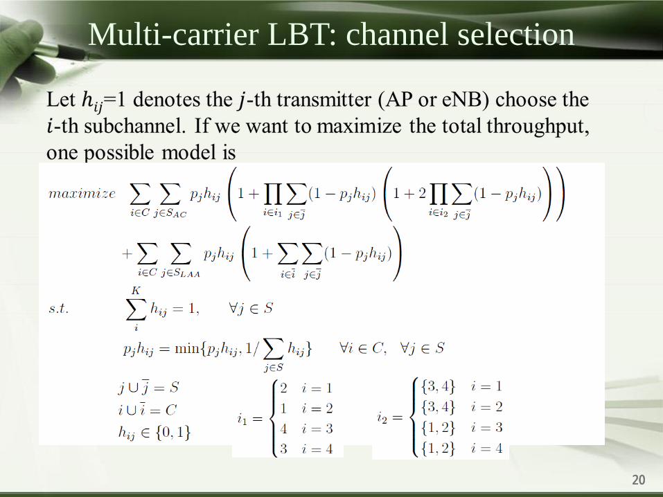
Multi-carrier LBT: channel selection

21
Next steps
Simulate the coexistence of 802.11ac with CB and LAA
with multi-carrier LBT
Continue to study channel selection algorithms