Study on Bending Strength of Web Bolted Moment Joints of ... · Bending strength of web-bolted...
11
Study on Bending Strength of Web-Bolted Moment Joints of Aluminum Alloy Beam Exposed to Fire HISASHI ISHII 1 , TAKEO HIRASHIMA 2 , and HIDEKI UESUGI 3 1 Global Business Department JS Group Corporation 3-3-2, Nihombashihamacho, Chuo-ku, Tokyo, 103-0007, Japan 2 Department of Architecture Graduate School of Engineering, Chiba University 1-33, Yayoi-cho, Inage-ku, Chiba-city 263-8522, Japan 3 Chiba University 1-33, Yayoi-cho, Inage-ku, Chiba-city 263-8522, Japan ABSTRACT This study narrows the application temperature field of aluminum alloy to 350 °C or less, and examines the strength of web-bolted moment joints within that temperature range. Bending strength of web-bolted moment joints of aluminum alloy exposed to fire is investigated experimentally and analytically. It is observed that if splice plate length and the beam section are designed appropriately, it is possible that maximum bending strength is fully realized with the web-bolted moment joints. The transmission mechanism of the bending moments is thought to be based on prying action between the flanges and splice plate side edge. The effect of prying action contributes to the maximum bending strength. Maximum bending strength ratio is 90–60 %. KEYWORDS: aluminum alloy beam, web-bolted joint, prying action, structural design, bending strength, FEM. NOMENCLATURE LISTING B width of H and DW beam (mm) i q x prying force of prying element on splice plate portion in x direction (kN) d prying element length (mm) j q x prying force of prying element on web portion in x direction (kN) H height of H and DW beam (mm) i q y prying force of prying element on splice plate portion in y direction (kN) h 1 distance from upper flange face to center of upper bolt hole (mm) j q y prying force of prying element on web portion in y direction (kN) h 2 distance from upper flange face to center of lower bolt hole (mm) t w web thickness (mm) M bending moment (kN·m) t f flange thickness (mm) M P peak bending moment (kN·m) Greek P BU bearing force of upper bolt on web portion (kN) δ displacement (mm) P BL bearing force of lower bolt on web portion (kN) θ deflection slope angle P C compression force of flange contact (kN) subscripts B bearing P LC prying force between upper flange and splice plate on center side (kN) C compression P LE prying force between upper flange and splice plate on edge side (kN) L prying P peak FIRE SAFETY SCIENCE-PROCEEDINGS OF THE TENTH INTERNATIONAL SYMPOSIUM, pp. 1139-1150 COPYRIGHT © 2011 INTERNATIONAL ASSOCIATION FOR FIRE SAFETY SCIENCE / DOI: 10.3801/IAFSS.FSS.10-1139 1139
Transcript of Study on Bending Strength of Web Bolted Moment Joints of ... · Bending strength of web-bolted...

Study on Bending Strength of Web-Bolted Moment Joints of Aluminum Alloy Beam Exposed to Fire
HISASHI ISHII1, TAKEO HIRASHIMA2, and HIDEKI UESUGI3 1Global Business Department JS Group Corporation 3-3-2, Nihombashihamacho, Chuo-ku, Tokyo, 103-0007, Japan 2Department of Architecture Graduate School of Engineering, Chiba University 1-33, Yayoi-cho, Inage-ku, Chiba-city 263-8522, Japan 3Chiba University 1-33, Yayoi-cho, Inage-ku, Chiba-city 263-8522, Japan
ABSTRACT
This study narrows the application temperature field of aluminum alloy to 350 °C or less, and examines the
strength of web-bolted moment joints within that temperature range. Bending strength of web-bolted
moment joints of aluminum alloy exposed to fire is investigated experimentally and analytically. It is
observed that if splice plate length and the beam section are designed appropriately, it is possible that
maximum bending strength is fully realized with the web-bolted moment joints. The transmission
mechanism of the bending moments is thought to be based on prying action between the flanges and splice
plate side edge. The effect of prying action contributes to the maximum bending strength. Maximum
bending strength ratio is 90–60 %.
KEYWORDS: aluminum alloy beam, web-bolted joint, prying action, structural design, bending strength,
FEM.
NOMENCLATURE LISTING
B width of H and DW beam (mm) iqx prying force of prying element on splice
plate portion in x direction (kN)
d prying element length (mm) jqx prying force of prying element on web
portion in x direction (kN)
H height of H and DW beam (mm) iqy prying force of prying element on splice
plate portion in y direction (kN)
h1 distance from upper flange face to center
of upper bolt hole (mm) jqy prying force of prying element on web
portion in y direction (kN)
h2 distance from upper flange face to center
of lower bolt hole (mm) tw web thickness (mm)
M bending moment (kN·m) tf flange thickness (mm)
MP peak bending moment (kN·m) Greek
PBU bearing force of upper bolt on web
portion (kN) δ displacement (mm)
PBL bearing force of lower bolt on web
portion (kN) θ deflection slope angle
PC compression force of flange contact (kN) subscripts
B bearing
PLC prying force between upper flange and
splice plate on center side (kN) C compression
PLE prying force between upper flange and
splice plate on edge side (kN) L prying
P peak
FIRE SAFETY SCIENCE-PROCEEDINGS OF THE TENTH INTERNATIONAL SYMPOSIUM, pp. 1139-1150 COPYRIGHT © 2011 INTERNATIONAL ASSOCIATION FOR FIRE SAFETY SCIENCE / DOI: 10.3801/IAFSS.FSS.10-1139
1139

INTRODUCTION
This study investigates the use of beams in atriums and pool roofs as architectural structures which employ
aluminum alloys, and especially consider the transfer of the bending moments of beam joints exposed to
fire. A temperature range of 20 °C to 350 °C is investigated; heating of specimens is by the use of an
electric furnace.
Traditionally, the purpose of friction joints of beams has been to provide rigidity. These joints have a high-
strength bolt going through splice plates, flanges and webs of H-beam steel beam sections (see Fig. 1a and
Fig. 2). However, this type of joint is difficult to design and construct, because it is affected by bending
moments (see Fig. 1b). It is possible to control the bending moment by using the web-bolted moment joint
shown in Fig. 3. This type of joint has already been proposed [1]. In Fig. 3, the web-bolted moment joint
connects only the web sections with high-strength bolts through the splice plates; the flange is not
connected.
In an experiment of a steel H-beam [1], this connection was shown to adequately transmit bending
moments. However, the direction of the bolt shearing force is different from that of a conventional bolt
joint connection [2], which is the vertical direction. Consequently, in the web-bolted joint, the shearing
force acts parallel to the axis of the member, and the splice plates are therefore bent as a result [3].
(a) (b)
Fig. 1. Photographs of: (a) traditional friction joint of a beam; (b) details on flange side of bolt and deck plate.
Fig. 2. Traditional friction joint of a beam.
Fig. 3. Web-bolted moment joint in H-shape steel beam.
Steel H-beam Splice plates
Gap>fillet portion
x
Steel H-beam
Splice plates
y
High-strength bolt (F10T
grade)
y
x
Gap>fillet portion
Steel H-beam
Splice plates
Steel H-beam Splice plates
High-strength bolt (F10T grade)
1140

PURPOSE OF THIS STUDY
This study examines web-bolted moment joints made from aluminum alloy members. Examples are shown
in Fig. 4 [4] and Fig. 5. In the web-bolted moment joints, the heights of the splice plates can be varied to
depths that are within 1mm between the beam flanges and the edges of the splices. This lower gap limit
allows considerable enhancement of the joint by increasing the height of the plate, unlike steel members.
Therefore, the web-bolted moment joint is a method for beams extruded with high accuracy, such as with
aluminum alloy beams. To use these connections in hollow beam sections, the splice plates are inserted
without gaps, as shown in Fig. 5.
It is also easy to form the hollow section in aluminum alloy members instead of the H-steel beam that is
commonly used. This joint method is referred to as a web-bolted moment joint of a double web-beam of
aluminum alloy.
Fig. 4. Aluminum H-beam with web-bolted moment joint.
Fig. 5. Aluminum double web-beam with web-bolted moment joint.
In the fire case, good structural performance is expected from the frame, and the connection is not expected
to fail prematurely before the frame collapse temperature [5]. Therefore, it is necessary to understand the
maximum bending strength and the fracture properties of the joints in fire-engineering designs. However,
there are no studies focusing on the maximum bending strength in beams subjected to the heat of a fire,
although there have been studies on the tensile components of high-strength bolt friction joints in aluminum
alloy members [7] and tensile tests at high temperatures [5].
This study narrows the application temperature field of aluminum alloy to 350 °C or less, and examines the
transformation of strength properties in web-bolted moment joints. The purpose of the study is to clarify the
fracture properties in fire engineering designs of an aluminum alloy structures with maximum bending
moments in the joints.
EXPERIMENT AND ANALYSIS
A bending strength experiment was conducted to clarify the maximum bending strength and fracture
properties of the web-bolted moment joint for the H-beam [4] and double web-beam at elevated
temperatures. The beam length was 600 mm.
Splice plates of
(F8T grade) High strength bolt
aluminum extrusion
H-beam of aluminum extrusion
Gap<1 mm
y
x
Gap<1 mm
Double web-shaped beam of aluminum extrusion
Splice plates of
aluminum extrusion
(F8T grade)
High-strength bolt
y
x
Gap<1 mm
Gap<1 mm
1141

The bolt layouts of the joints are shown in Fig. 6 and the experimental conditions are listed in Tables 1
and 2. The lengths and temperatures of the section shape, the splice plates, the bolt layouts, and the beam
material were considered as factors affecting the bending strength and transfer performance in the web-
bolted moment joints. The bolt layouts, the temperatures of the bolts, and the lengths of the splice plates are
compared by varying the five factors affecting bending strength: the bolt layout, temperature, beam
material, the double web-beam shape and the H-beam shape [3]. Figures 7a and b show the results of the
double-web beam at room temperature and 300 °C, respectively. Figures 8a and b show the results of the
H-beam.
H-B4-T 2 line, 4 row H-B2-T 2 line, 2row
4)
DW-CL-T 2 line, 2 row DW-CL-T 2 line, 1row
DW-CS-T 2 line, 1 row DW-CL-T 1 line, 1row
Fig. 6. Bolt arrays of specimens (for one joint).
H-beam - 150×150×8×10 Splice plate 128×15
405 450 450
Double Web-beam - 150×150×8×10
5
80 120 80
405 410 410
120
Splice plate 128×15
Double Web-beam - 150×150×8×10 Splice plate 128×15
H-Beam Double web beam
150
5
40 〃 〃 40 〃 40 〃 〃 40 〃 40 80 40 80 80 80
5
405 450 450
12
8
11
1
1
12
8
11
1
1
60 4
5
45
60 4
5
45
x
y
x
y
x
y
40 80 40 80 80 80
5
405 410 410 150
60.5
12
8
11
1
1
12
8
11
1
1
60 4
5
45
60 4
5
45
5
80 120 80
405 410 410
120
5
80 40 80
245 490 490
40
150
60.5
75
75 12
8
11
1
1
12
8
11
1
1
60 4
5
45
1142

Table 1. Bending experimental conditions of double-web beam.
Splice plate
length (mm)
Bolts array Room
temperature
200 °C 300 °C
No joint No splice plate B0-C0-T000 B0-C0-T200 B0-C0-T300
405 1 line 1 row B1-CL-T000 B1-CL-T200 B1-CL-T300
405 2 line 1 row B2-CL-T000 B2-CL-T200 B2-CL-T300
405 2 line 2 row B4-CL-T000 B4-CL-T200 B4-CL-T300
245 2 line 1 row B2-CS-T000 B2-CS-T200 B2-CS-T300
Table 2. Bending experimental conditions of H-beam [4].
Bolts array RT 100 °C 200 °C 250 °C 300 °C 350 °C
No splice plate B0-T000 B0-T100 B0-T200 B0-T250 B0-T300 B0-T350
2 line 2 row B2-T000 B2-T100 B2-T200 B2-T250 B2-T300 B2-T350
2 line 4 row B4-T000 B4-T100 B4-T200 B4-T250 B4-T300 B4-T350
In these figures, vertical axis shows the ratio between experimental moment and plastic one at room
temperature and horizontal axis shows the ratio between experimental deflection slope angle and limited
one 1/150 mm.
(a) (b)
Fig. 7. Experimental result Double web-beam of: (a) room temperature; (b) 300 °C.
(a) (b)
Fig. 8. Experimental result H-beam of: (a) room temperature; (b) 300 °C.
0
0.2
0.4
0.6
0.8
1
1.2
0 0.04 0.08 0.12 0.16
H Shape-B0-T000
H Shape-B2-T000
H Shape-B4-T000
PMM
150
1.2
1.0
0.8
0
0.6
0.4
0.2
0 0.04 0.08 0.12 0.16
H Shape-B0- T000
H Shape-B2- T000 H Shape-B4- T000
H -B0
H -B2
H -B4
0
0.2
0.4
0.6
0.8
1
1.2
0 0.04 0.08 0.12 0.16
H Shape-B0-T300
H Shape-B2-T300
H Shape-B4-T300
PMM
150
1.2
1.0
0.8
0
0.6
0.4
0.2
0 0.04 0.08 0.12 0.16
H Shape-B0- T300
H Shape-B2- T300
H Shape-B4- T300
H -B0 H -B2
H -B4
0
0.2
0.4
0.6
0.8
1
1.2
0 0.04 0.08 0.12 0.16
DW-B0-C0-T000 DW-B1-CL-T000 DW-B2-CL-T000 DW-B2-CS-T000 DW-B4-CL-T000
0
0.2
0.4
0.6
0.8
1
1.2
0 0.04 0.08 0.12 0.16
DW-B0-C0-T300DW-B1-CL-T300DW-B2-CL-T300DW-B2-CS-T300DW-B4-CL-T300
PMM
150
1.2
1.0
0.8
0
0.6
0.4
0.2
0 0.04 0.08 0.12 0.16
DW-B0-C0-T300 DW-B1-CL-T300 DW-B2-CL-T300 DW-B2-CS-T300 DW-B4-CL-T300
B0- C0
B2- CS
B1- CL B2- CL B4-CL
PMM
150
1.2
1.0
0.8
0
0.6
0.4
0.2
0 0.04 0.08 0.12 0.16
DW-B0-C0-T000 DW-B1-CL-T000 DW-B2-CL-T000 DW-B2-CS-T000 DW-B4-CL-T000
B0- C0 B1- CL
B4-CL B2- CL
B2- CS
150
1143

The Maximum Bending Strength and Factors Affecting the Strength
In the web-bolted moment joints of the double-web beam (excluding the joint of splice plate length
245 mm), at room temperature and at 300 °C, the maximum bending strength was found to be equal to the
beam with no joints (See Figs. 7a and b).
In the H-beam, at room temperature the maximum bending strength occurred for the beam with no joints,
although at 300 °C and 350 °C the beam with no joints had a bending strength of 70 % of the maximum
bending strength of that up to 250 °C [4] (See Figs. 8a and b).
It was concluded that the splice plate length is a factor affecting the maximum bending strength. In the
double-web beam, 150 mm in width between the two webs, it was concluded that the splice plate length
was a factor affecting the maximum bending strength. The beam with splice plates 245 mm in length had
about 70 % of the maximum bending strength of the beam that had a 405 mm splice (see Figs. 7a and b).
In summary, the length of the splice plate greatly influences the maximum bending strength. The effect of
the bolt arrays is minimal, even though the bolt array was assumed to be a factor. The equal, maximum
bending strength was as a result of either one row one step (1 bolt) or two step two rows (4 bolts) (see
Fig. 7a).
Collapse Properties
The deflection of the H-beam [4], and double-web beam and the rotation angle were not affected by the
presence or absence of joints when the temperature exceeded 300 °C, and the fracture was up to 0.16 (four
times value of the allowable limit indicated in ISO834) (see Fig. 9 and Fig. 10).
The joints did not easily collapse at 300 °C or higher, although there were specimens that collapsed after
reaching the maximum bending strength at room temperature up to 250 °C (see Fig. 11). It was clarified
that the work hardening and elongation at 250 °C and below were smaller for the aluminum alloy compared
with steel, as shown by tension tests at elevated temperature.
In the H- beam, edge of collapse of the web occurred for specimens at room temperature up to 250 °C [4]
(see Fig.13). In the double-web beam, punching shear caused tensile collapse of the flange (see Fig. 11) and
near the web fillet (see Fig. 12). At 250 °C or less, the concentrated stress easily causes brittle collapse.
Fig. 9. Photograph of 2 line 2 row at splice plate 300 °C in double web-beam experimental result.
1144

Fig. 10. Photograph of 1 line 1 row at beam joint 300 °C in double web-beam experimental result.
Fig. 11. Photograph of 1 line 1 row at beam joint 200 °C in double web-beam experimental result.
Fig.12. Photograph of 1 line 1 row at beam joint edge 200 °C in double web-beam experiment result.
Fig. 13. Photograph of 2 line 4 row at beam joint 100 °C in H-beam experimental result [4].
1145

Fig. 14. Photograph of 2 line 2 row at beam joint RT in H-beam experimental result[4].
Effect of Prying Action
At 200 °C or higher in the high-strength bolt friction joint in the aluminum alloy, the bolt axis force
decreases and tensile strength decreases rapidly, this decreasing phenomenon has been previously reported
[7].
Due to the decrease of axis force in the high-strength bolt because of the rise in temperature, prying action
is generated, as a result of bearing between the splice plate and the flange (see Fig. 14). Therefore, positive
transmission of the bending moment is predicted by the prying action and not by the bending moment in
the joint. It is thought that it is advantageous to be able to reduce the gap between the splice plates side
edge and the flange when prying action is used.
In this study, it was assumed that transfer of bending moment is possible by prying action, and modeling of
the web bolted moment joint of the prying action of the aluminum alloy beam was considered (see Fig. 15).
Fig. 15. Generation of prying reaction and bearing action in beam joint force.
The transmission of the bending moment with the web-bolted moment joint of the aluminum alloy beam is
frictional at first, and after slipping there is rotation at the bolt section due to shearing of the bolt and
bearing of the web plate. However, in this study, prying action by the bearing with the bolt between the
web, splice plates, and beam flange is expected without transmission of the frictional bending moment.
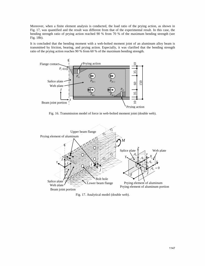
The bearing influence on the bolts and the prying action between the beam flange and the splice plate was
examined. The load ratio of the prying action between the splice plate and the maximum bending bearing
force of the web-bolted moment joint and the flange was quantitatively evaluated by experiment. Figure 16
shows the model used. The bending strength ratio of prying action reached 90 % from 60 % of the
maximum bending strength (see Fig. 18a).
This indicates are contact of beam flange and splice plate.
H 2h
B
Section of beam
at beam joint portion
ft
Contact of beam
flange and splice plate
M neutral
plane 2
wt
Beam joint
2
wt
neutral axis 1h
M
1146
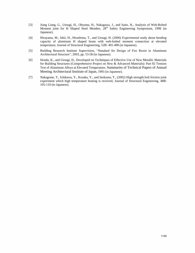
Moreover, when a finite element analysis is conducted, the load ratio of the prying action, as shown in
Fig. 17, was quantified and the result was different from that of the experimental result. In this case, the
bending strength ratio of prying action reached 90 % from 70 % of the maximum bending strength (see
Fig. 18b).
It is concluded that the bending moment with a web-bolted moment joint of an aluminum alloy beam is
transmitted by friction, bearing, and prying action. Especially, it was clarified that the bending strength
ratio of the prying action reaches 90 % from 60 % of the maximum bending strength.
Fig. 16. Transmission model of force in web-bolted moment joint (double web).
Fig. 17. Analytical model (double web).
MPrying element of aluminum
CL
ZY X
Splice plate Lower beam flange Prying element of aluminum
xi qY X
xj q
Z
x
y
z0yj q
yi q
d
Upper beam flange
Web plate
Beam joint portion Prying element of aluminum portion
Splice plate Web plate
Bolt hole
1BLP2BLP
1BUP 2BUP
CP
LCP
LEP
X
Z
15
0
60
35
35
10
10
Beam joint portion
Splice plate
Web plate
Prying action
Prying action Flange contact
CL
j
ii
j
1147

(a) (b)
Fig. 18. Prying action ratio of: (a) experimental result (rough estimate); (b) analysis result and rough estimate.
CONCLUSION
The following mechanisms of bending strength for the H-beam and double-web beam of aluminum alloy
were observed experimentally and analytically.
1) The maximum bearing moment of the beam with the double web-bolted moment joint is almost equal
to the moment of a beam without a joint. For H-beams it is 70 %.
2) The effect of prying action contributes to the maximum bending strength. Prying action ratio is 90–
60 % of maximum bending strength.
3) In specimens tested in the range of room temperature to 250 °C, there was tensile fracture by the
bearings, prying action between the boundary of the web and the flange portion, and punching shear
fracture.
4) For the specimens tested at 300 °C and 350 °C, because the bending transformation by the prying
action had progressed, brittle fracture was not seen.
When the web-bolted moment joint was used, valuable data concerning the bending moment transmission
at fire temperatures was obtained. In the aluminum alloy structure, it is necessary to secure the toughness of
the joint section if sustained loading was expected so that collapse is avoided at 300 °C or above. In the
past, there has been no standard method concerning joints in the design of fire resistance in aluminum
architectural structures. Information for fire resistance of the joints of aluminum structures was presented in
this paper.
FUTURE TASKS
The following studies must be conducted:
1) Clarification of the behavior of beams subjected to shearing force.
2) Establishment of a design formula based on bending in the shearing study.
3) Development of practical section distribution of the prying force.
REFERENCES
[1] Niwa, H., Zhou, Z.M., Kuramoto, S., Uesugi, H., Saito, H., and Ohyama, H., (1994) Web bolted
moment joint of H shape steel beam, Journal of Structural Engineering, Architectural Institute of
Japan, 40B: 695-702 (in Japanese).
[2] Architectural Institute of Japan, “Recommendation for Design of Connections in Steel Structures”,
2006 (in Japanese).
梃子作用
の割合
0.00
0.10
0.20
0.30
0.40
0.50
0.60
0.70
0.80
0.90
1.00
0 100 200 300 400
割
合
DW B1-CL-T DW B4-CL-T DW B2-CL-T DW B2-CS-T H 形 B2-T H 形 B4-T
°C
Ratio
H B2-T H B4-T
0 100 200 300 温度(
℃)
0.00
0.10
0.20
0.30
0.40
0.50
0.60
0.70
0.80
0.90
1.00
0 100 200 300 温度(℃)
割合
解析結果H形
解析結果DW
概算H形
概算DW
H shape (analysis)
DW shape (analysis)
DW shape (Rough estimate)
H shape (Rough estimate)
°C
Ratio
0.90
1.00
0.70
0.80
0.60
0.50
0.40
0.30
0.20
0.10
0.00
0 100 200 300
DW(analysis)
H (estimate) DW(estimate)
H (analysis)
DW-B1-CL DW-B2-CL
DW-B4-CL
DW-B2-CS
H-B2
H-B4
2line 1row
1148
[3] Jiang Liang, G., Uesugi, H., Ohyama, H., Nakagawa, J., and Saito, H., Analysis of Web-Bolted
Moment joint for H Shaped Steel Member, 28th Safety Engineering Symposium, 1998 (in
Japanese).
[4] Hirayama, M., Ishii, H., Hirashima, T., and Uesugi, H. (2006) Experimental study about bending
capacity of aluminum H shaped beam with web-bolted moment connection at elevated
temperature, Journal of Structural Engineering, 52B: 401-408 (in Japanese).
[5] Building Research Institute Supervision, “Standard for Design of Fire Resist in Aluminum
Architectural Structure”, 2003, pp. 53-58 (in Japanese).
[6] Honda, K., and Uesugi, H., Developed on Techniques of Effective Use of New Metallic Materials
for Building Structures (Comprehensive Project on New & Advanced Materials): Part 92 Tension
Test of Aluminum Alloys at Elevated Temperature, Summaries of Technical Papers of Annual
Meeting Architectural Institute of Japan, 1993 (in Japanese).
[7] Nakagome, T., Ichikawa, Y., Kosaka, Y., and Inokuma, T., (2002) High strength bolt friction joint
experiment which high temperature heating is received, Journal of Structural Engineering, 48B:
105-110 (in Japanese).
1149