Study of workpiece thermal profile in Electrical Discharge ... · PDF fileof parameter...
10
Study of workpiece thermal profile in Electrical Discharge Machining (EDM) process Ali MOARREFZADEH Faculty Member of Mechanical Engineering Department, Mahshahr Branch, Islamic Azad University, Mahshahr, Iran [email protected] [email protected] Abstract: Electric Discharge Machining (EDM) removes metal with sparks. A shaped graphite or copper electrode is used to make a cavity that is the mirror image of the electrode, without direct contact with the workpiece. Sparks travel through a dielectric fluid, typically a light oil, at a controlled distance. EDM can machine cavities with thin walls and fine features, achieve difficult part geometry, produce burr-free parts, and is insensitive to workpiece hardness.The values of these parameters significantly affect such machining outputs as material removal rate and electrodes wear. In this paper, the mathematical relationships between input and output parameters of EDM are established using regression method and the best set of models is chosen. Genetic Algorithm is then used to optimally determine input parameters levels in order to obtain any desired set of outputs. Numerical simulation of process in ANSYS software an for gaining the thermal profile, the effect of parameter variation on temperature field and process optimization are done. The numerical results show the time-dependant distributions of arc pressure, current density, and heat transfer at the workpiece surface are different from presumed Gaussian distributions in previous models. Key-Words: EDM parameters, Workpiece, Discharge , Machining, ANSYS 1 Introduction In EDM, a potential difference is applied between the tool and workpiece. Both the tool and the work material are to be conductors of electricity. The tool and the work material are immersed in a dielectric medium. Generally kerosene or deionised water is used as the dielectric medium. A gap is maintained between the tool and the workpiece. Depending upon the applied potential difference and the gap between the tool and workpiece, an electric field would be established. Generally the tool is connected to the negative terminal of the generator and the workpiece is connected to positive terminal. As the electric field is established between the tool and the job, the free electrons on the tool are subjected to electrostatic forces. If the work function or the bonding energy of the electrons is less, electrons would be emitted from the tool (assuming it to be connected to the negative terminal). Such emission of electrons are called or termed as cold emission. The “cold emitted” electrons are then accelerated towards the job through the dielectric medium. As they gain velocity and energy, and start moving towards the job, there would be collisions between the electrons and dielectric molecules. Such collision may result in ionisation of the dielectric molecule depending upon the work function or ionisation energy of the dielectric molecule and the energy of the electron. Thus, as the electrons get accelerated, more positive ions and electrons would get generated due to collisions. This cyclic process would increase the concentration of electrons and ions in the dielectric medium between the tool and the job at the spark gap. The concentration would be so high that the matter existing in that channel could be characterised as “plasma”. The electrical resistance of such plasma channel would be very less. Thus all of a sudden, a large number of electrons will flow from the tool to the job and ions from the job to the tool. This is called avalanche motion of electrons. Such movement of electrons and ions can be visually seen WSEAS TRANSACTIONS on APPLIED and THEORETICAL MECHANICS Ali Moarrefzadeh E-ISSN: 2224-3429 83 Issue 2, Volume 7, April 2012
Transcript of Study of workpiece thermal profile in Electrical Discharge ... · PDF fileof parameter...
Study of workpiece thermal profile in
Electrical Discharge Machining (EDM) process
Ali MOARREFZADEH
Faculty Member of Mechanical Engineering Department,
Mahshahr Branch,
Islamic Azad University, Mahshahr, Iran
Abstract: Electric Discharge Machining (EDM) removes metal with sparks. A shaped graphite or copper
electrode is used to make a cavity that is the mirror image of the electrode, without direct contact with the
workpiece. Sparks travel through a dielectric fluid, typically a light oil, at a controlled distance. EDM can
machine cavities with thin walls and fine features, achieve difficult part geometry, produce burr-free parts, and
is insensitive to workpiece hardness.The values of these parameters significantly affect such machining outputs
as material removal rate and electrodes wear. In this paper, the mathematical relationships between input and
output parameters of EDM are established using regression method and the best set of models is chosen.
Genetic Algorithm is then used to optimally determine input parameters levels in order to obtain any desired set
of outputs. Numerical simulation of process in ANSYS software an for gaining the thermal profile, the effect
of parameter variation on temperature field and process optimization are done. The numerical results show the
time-dependant distributions of arc pressure, current density, and heat transfer at the workpiece surface are
different from presumed Gaussian distributions in previous models.
Key-Words: EDM parameters, Workpiece, Discharge , Machining, ANSYS
1 Introduction In EDM, a potential difference is applied between
the tool and workpiece. Both the tool and the work
material are to be conductors of electricity. The tool
and the work material are immersed in a dielectric
medium. Generally kerosene or deionised water is
used as the dielectric medium. A gap is maintained
between the tool and the workpiece. Depending
upon the applied potential difference and the gap
between the tool and workpiece, an electric field
would be established. Generally the tool is
connected to the negative terminal of the generator
and the workpiece is connected to positive terminal.
As the electric field is established between the tool
and the job, the free electrons on the tool are
subjected to electrostatic forces. If the work function
or the bonding energy of the electrons is less,
electrons would be emitted from the tool (assuming
it to be connected to the negative terminal). Such
emission of electrons are called or termed as cold
emission. The “cold emitted” electrons are then
accelerated towards the job through the dielectric
medium. As they gain velocity and energy, and start
moving towards the job, there would be collisions
between the electrons and dielectric molecules.
Such collision may result in ionisation of the
dielectric molecule depending upon the work
function or ionisation energy of the dielectric
molecule and the energy of the electron. Thus, as
the electrons get accelerated, more positive ions and
electrons would get generated due to collisions. This
cyclic process would increase the concentration of
electrons and ions in the dielectric medium between
the tool and the job at the spark gap. The
concentration would be so high that the matter
existing in that channel could be characterised as
“plasma”. The electrical resistance of such plasma
channel would be very less. Thus all of a sudden, a
large number of electrons will flow from the tool to
the job and ions from the job to the tool. This is
called avalanche motion of electrons. Such
movement of electrons and ions can be visually seen
WSEAS TRANSACTIONS on APPLIED and THEORETICAL MECHANICS Ali Moarrefzadeh
E-ISSN: 2224-3429 83 Issue 2, Volume 7, April 2012
as a spark. Thus the electrical energy is dissipated as
the thermal energy of the spark.
The high speed electrons then impinge on the job
and ions on the tool. The kinetic energy of the
electrons and ions on impact with the surface of the
job and tool respectively would be converted into
thermal energy or heat flux. Such intense localised
heat flux leads to extreme instantaneous confined
rise in temperature which would be in excess of
10,000o
C.
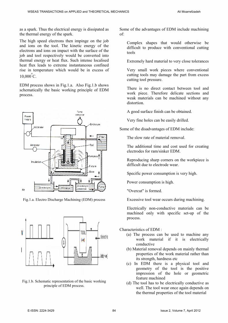
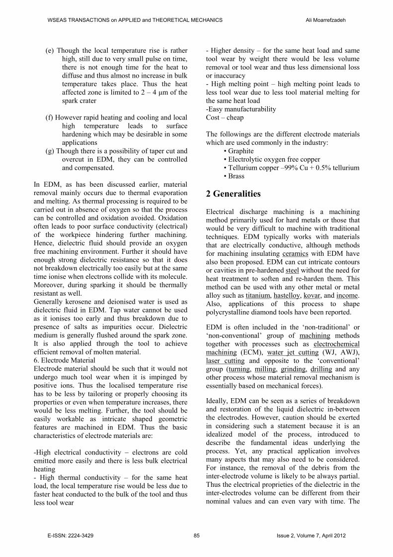
EDM process shows in Fig.1.a. Also Fig.1.b shows
schematically the basic working principle of EDM
process.
Fig.1.a. Electro Discharge Machining (EDM) process
Fig.1.b. Schematic representation of the basic working
principle of EDM process.
Some of the advantages of EDM include machining
of:
Complex shapes that would otherwise be
difficult to produce with conventional cutting
tools
Extremely hard material to very close tolerances
Very small work pieces where conventional
cutting tools may damage the part from excess
cutting tool pressure.
There is no direct contact between tool and
work piece. Therefore delicate sections and
weak materials can be machined without any
distortion.
A good surface finish can be obtained.
Very fine holes can be easily drilled.
Some of the disadvantages of EDM include:
The slow rate of material removal.
The additional time and cost used for creating
electrodes for ram/sinker EDM.
Reproducing sharp corners on the workpiece is
difficult due to electrode wear.
Specific power consumption is very high.
Power consumption is high.
"Overcut" is formed.
Excessive tool wear occurs during machining.
Electrically non-conductive materials can be
machined only with specific set-up of the
process.
Characteristics of EDM :
(a) The process can be used to machine any
work material if it is electrically
conductive
(b) Material removal depends on mainly thermal
properties of the work material rather than
its strength, hardness etc
(c) In EDM there is a physical tool and
geometry of the tool is the positive
impression of the hole or geometric
feature machined
(d) The tool has to be electrically conductive as
well. The tool wear once again depends on
the thermal properties of the tool material
WSEAS TRANSACTIONS on APPLIED and THEORETICAL MECHANICS Ali Moarrefzadeh
E-ISSN: 2224-3429 84 Issue 2, Volume 7, April 2012
(e) Though the local temperature rise is rather
high, still due to very small pulse on time,
there is not enough time for the heat to
diffuse and thus almost no increase in bulk
temperature takes place. Thus the heat
affected zone is limited to 2 – 4 µm of the
spark crater
(f) However rapid heating and cooling and local
high temperature leads to surface
hardening which may be desirable in some
applications
(g) Though there is a possibility of taper cut and
overcut in EDM, they can be controlled
and compensated.
In EDM, as has been discussed earlier, material
removal mainly occurs due to thermal evaporation
and melting. As thermal processing is required to be
carried out in absence of oxygen so that the process
can be controlled and oxidation avoided. Oxidation
often leads to poor surface conductivity (electrical)
of the workpiece hindering further machining.
Hence, dielectric fluid should provide an oxygen
free machining environment. Further it should have
enough strong dielectric resistance so that it does
not breakdown electrically too easily but at the same
time ionise when electrons collide with its molecule.
Moreover, during sparking it should be thermally
resistant as well.
Generally kerosene and deionised water is used as
dielectric fluid in EDM. Tap water cannot be used
as it ionises too early and thus breakdown due to
presence of salts as impurities occur. Dielectric
medium is generally flushed around the spark zone.
It is also applied through the tool to achieve
efficient removal of molten material.
6. Electrode Material
Electrode material should be such that it would not
undergo much tool wear when it is impinged by
positive ions. Thus the localised temperature rise
has to be less by tailoring or properly choosing its
properties or even when temperature increases, there
would be less melting. Further, the tool should be
easily workable as intricate shaped geometric
features are machined in EDM. Thus the basic
characteristics of electrode materials are:
-High electrical conductivity – electrons are cold
emitted more easily and there is less bulk electrical
heating
- High thermal conductivity – for the same heat
load, the local temperature rise would be less due to
faster heat conducted to the bulk of the tool and thus
less tool wear
- Higher density – for the same heat load and same
tool wear by weight there would be less volume
removal or tool wear and thus less dimensional loss
or inaccuracy
- High melting point – high melting point leads to
less tool wear due to less tool material melting for
the same heat load
-Easy manufacturability
Cost – cheap
The followings are the different electrode materials
which are used commonly in the industry:
• Graphite
• Electrolytic oxygen free copper
• Tellurium copper –99% Cu + 0.5% tellurium
• Brass
2 Generalities
Electrical discharge machining is a machining
method primarily used for hard metals or those that
would be very difficult to machine with traditional
techniques. EDM typically works with materials
that are electrically conductive, although methods
for machining insulating ceramics with EDM have
also been proposed. EDM can cut intricate contours
or cavities in pre-hardened steel without the need for
heat treatment to soften and re-harden them. This
method can be used with any other metal or metal
alloy such as titanium, hastelloy, kovar, and income.
Also, applications of this process to shape
polycrystalline diamond tools have been reported.
EDM is often included in the ‘non-traditional’ or
‘non-conventional’ group of machining methods
together with processes such as electrochemical
machining (ECM), water jet cutting (WJ, AWJ),
laser cutting and opposite to the ‘conventional’
group (turning, milling, grinding, drilling and any
other process whose material removal mechanism is
essentially based on mechanical forces).
Ideally, EDM can be seen as a series of breakdown
and restoration of the liquid dielectric in-between
the electrodes. However, caution should be exerted
in considering such a statement because it is an
idealized model of the process, introduced to
describe the fundamental ideas underlying the
process. Yet, any practical application involves
many aspects that may also need to be considered.
For instance, the removal of the debris from the
inter-electrode volume is likely to be always partial.
Thus the electrical proprieties of the dielectric in the
inter-electrodes volume can be different from their
nominal values and can even vary with time. The
WSEAS TRANSACTIONS on APPLIED and THEORETICAL MECHANICS Ali Moarrefzadeh
E-ISSN: 2224-3429 85 Issue 2, Volume 7, April 2012
inter-electrode distance, often also referred to as
spark-gap, is the end result of the control algorithms
of the specific machine used. The control of such a
distance appears logically to be central to this
process. Also, not all of the current between the
dielectric is of the ideal type described above: the
spark-gap can be short-circuited by the debris. The
control system of the electrode may fail to react
quickly enough to prevent the two electrodes (tool
and workpiece) to get in contact, with a consequent
short circuit. This is unwanted because a short
circuit contributes to the removal differently from
the ideal case. The flushing action can be inadequate
to restore the insulating properties of the dielectric
so that the current always happens in the point of the
inter-electrode volume (this is referred to as arcing),
with a consequent unwanted change of shape
(damage) of the tool-electrode and workpiece.
Ultimately, a description of this process in a suitable
way for the specific purpose at hand is what makes
the EDM area such a rich field for further
investigation and research.
To obtain a specific geometry, the EDM tool is
guided along the desired path very close to the
work; ideally it should not touch the workpiece,
although in reality this may happen due to the
performance of the specific motion control in use. In
this way, a large number of current discharges
(colloquially also called sparks) happen, each
contributing to the removal of material from both
tool and workpiece, where small craters are formed.
The size of the craters is a function of the
technological parameters set for the specific job at
hand. They can be with typical dimensions ranging
from the nanoscale (in micro-EDM operations) to
some hundreds of micrometers in roughing
conditions.
The presence of these small craters on the tool
results in the gradual erosion of the electrode. This
erosion of the tool-electrode is also referred to as
wear. Strategies are needed to counteract the
detrimental effect of the wear on the geometry of
the workpiece. One possibility is that of
continuously replacing the tool-electrode during a
machining operation. This is what happens if a
continuously replaced wire is used as electrode. In
this case, the correspondent EDM process is also
called wire EDM. The tool-electrode can also be
used in such a way that only a small portion of it is
actually engaged in the machining process and this
portion is changed on a regular basis. This is, for
instance, the case when using a rotating disk as a
tool-electrode. The corresponding process is often
also referred to as EDM grinding.
A further strategy consists in using a set of
electrodes with different sizes and shapes during the
same EDM operation. This is often referred to as
multiple electrode strategy, and is most common
when the tool electrode replicates in negative the
wanted shape and is advanced towards the blank
along a single direction, usually the vertical
direction (i.e. z-axis). This resembles the sink of the
tool into the dielectric liquid in which the workpiece
is immersed, so, not surprisingly, it is often referred
to as die-sinking EDM (also called conventional
EDM and ram EDM). The corresponding machines
are often called sinker EDM. Usually, the electrodes
of this type have quite complex forms. If the final
geometry is obtained using a usually simple-shaped
electrode which is moved along several directions
and is possibly also subject to rotations, often the
term EDM milling is used.
In any case, the severity of the wear is strictly
dependent on the technological parameters used in
the operation (for instance: polarity, maximum
current, open circuit voltage). For example, in
micro-EDM, also known as µ-EDM, these
parameters are usually set at values which generates
severe wear. Therefore, wear is a major problem in
that area.
The problem of wear to graphite electrodes is being
addressed. In one approach, a digital generator,
controllable within milliseconds, reverses polarity as
electro-erosion takes place. That produces an effect
similar to electroplating that continuously deposits
the eroded graphite back on the electrode. In another
method, a so-called "Zero Wear" circuit reduces
how often the discharge starts and stops, keeping it
on for as long a time as possible.
3 Numerical simulation
Finite elements simulations are done in 3 steps with
the main pieces:
1- Modeling by FEMB
2- The thermal study and processing
3- Post-Processing result of analysis by
ANSYS software for results discussion
WSEAS TRANSACTIONS on APPLIED and THEORETICAL MECHANICS Ali Moarrefzadeh
E-ISSN: 2224-3429 86 Issue 2, Volume 7, April 2012
Finite-Element techniques:
1-Finite elements modeling, types and properties
for model different parts.
2- The definition of material properties
3- parameter definition
4- Loading
5- Boundary and initial value definition
6- Common interfaces definition
7- Control parameter definition
Small hole drilling EDM is used in a variety of
applications.
On wire-cut EDM machines, small hole drilling
EDM is used to make a through hole in a workpiece
in through which to thread the wire for the wire-cut
EDM operation. A separate EDM head specifically
for small hole drilling is mounted on a wire-cut
machine and allows large hardened plates to have
finished parts eroded from them as needed and
without pre-drilling.
Small hole EDM is used to drill rows of holes into
the leading and trailing edges of turbine blades used
in jet engines. Gas flow through these small holes
allows the engines to use higher temperatures than
otherwise possible. The high-temperature, very
hard, single crystal alloys employed in these blades
makes conventional machining of these holes with
high aspect ratio extremely difficult, if not
impossible.
Small hole EDM is also used to create microscopic
orifices for fuel system components, spinnerets for
synthetic fibers such as rayon, and other
applications.
There are also stand-alone small hole drilling EDM
machines with an x–y axis also known as a super
drill or hole popper that can machine blind or
through holes. EDM drills bore holes with a long
brass or copper tube electrode that rotates in a chuck
with a constant flow of distilled or demonized water
flowing through the electrode as a flushing agent
and dielectric. The electrode tubes operate like the
wire in wire-cut EDM machines, having a spark gap
and wear rate. Some small-hole drilling EDMs are
able to drill through 100 mm of soft or through
hardened steel in less than 10 seconds, averaging
50% to 80% wear rate. Holes of 0.3 mm to 6.1 mm
can be achieved in this drilling operation. Brass
electrodes are easier to machine but are not
recommended for wire-cut operations due to eroded
brass particles causing "brass on brass" wire
breakage, therefore copper is recommended.
Difficulties have been encountered in the definition
of the technological parameters that drive the
process.
Two broad categories of generators, also known as
power supplies, are in use on EDM machines
commercially available: the group based on RC
circuits and the group based on transistor controlled
pulses.
In the first category, the main parameters to choose
from at setup time are the resistance(s) of the
resistor(s) and the capacitance(s) of the capacitor(s).
In an ideal condition these quantities would affect
the maximum current delivered in a discharge which
is expected to be associated with the charge
accumulated on the capacitors at a certain moment
in time. Little control, however, is expected over the
time duration of the discharge, which is likely to
depend on the actual spark-gap conditions (size and
pollution) at the moment of the discharge. The RC
circuit generator can allow the user to obtain short
time durations of the discharges more easily than the
pulse-controlled generator, although this advantage
is diminishing with the development of new
electronic components.[13]
Also, the open circuit
voltage (i.e. the voltage between the electrodes
when the dielectric is not yet broken) can be
identified as steady state voltage of the RC circuit.
In generators based on transistor control, the user is
usually able to deliver a train of pulses of voltage to
the electrodes. Each pulse can be controlled in
shape, for instance, quasi-rectangular. In particular,
the time between two consecutive pulses and the
duration of each pulse can be set. The amplitude of
each pulse constitutes the open circuit voltage.
Thus, the maximum duration of discharge is equal
to the duration of a pulse of voltage in the train.
Two pulses of current are then expected not to occur
for a duration equal or larger than the time interval
between two consecutive pulses of voltage.
The maximum current during a discharge that the
generator delivers can also be controlled. Because
other sorts of generators may also be used by
different machine builders, the parameters that may
actually be set on a particular machine will depend
on the generator manufacturer. The details of the
WSEAS TRANSACTIONS on APPLIED and THEORETICAL MECHANICS Ali Moarrefzadeh
E-ISSN: 2224-3429 87 Issue 2, Volume 7, April 2012
generators and control systems on their machines
are not always easily available to their user. This is
a barrier to describing unequivocally the
technological parameters of the EDM process.
Moreover, the parameters affecting the phenomena
occurring between tool and electrode are also
related to the controller of the motion of the
electrodes.
A framework to define and measure the electrical
parameters during an EDM operation directly on
inter-electrode volume with an oscilloscope external
to the machine has been recently proposed by Ferri
et al.[14]
These authors conducted their research in
the field of µ-EDM, but the same approach can be
used in any EDM operation. This would enable the
user to estimate directly the electrical parameter that
affect their operations without relying upon machine
manufacturer's claims. Finally, it is worth
mentioning that when machining different materials
in the same setup conditions, the actual electrical
parameters of the process are significantly different.
The first serious attempt of providing a physical
explanation of the material removal during electric
discharge machining is perhaps that of Van Dijck.
Van Dijck presented a thermal model together with
a computational simulation to explain the
phenomena between the electrodes during electric
discharge machining. However, as Van Dijck
himself admitted in his study, the number of
assumptions made to overcome the lack of
experimental data at that time was quite significant.
Further models of what occurs during electric
discharge machining in terms of heat transfer were
developed in the late eighties and early nineties,
including an investigation at Texas A&M University
with the support of AGIE, now Agiecharmilles. It
resulted in three scholarly papers: the first
presenting a thermal model of material removal on
the cathode,[16]
the second presenting a thermal
model for the erosion occurring on the anode[17]
and
the third introducing a model describing the plasma
channel formed during the passage of the discharge
current through the dielectric liquid.[18]
Validation of
these models is supported by experimental data
provided by AGIE.
These models give the most authoritative support
for the claim that EDM is a thermal process,
removing material from the two electrodes because
of melting and/or vaporization, along with pressure
dynamics established in the spark-gap by the
collapsing of the plasma channel. However, for
small discharge energies the models are inadequate
to explain the experimental data. All these models
hinge on a number of assumptions from such
disparate research areas as submarine explosions,
discharges in gases, and failure of transformers, so it
is not surprising that alternative models have been
proposed more recently in the literature trying to
explain the EDM process.
Among these, the model from Singh and Ghosh
reconnects the removal of material from the
electrode to the presence of an electrical force on the
surface of the electrode that could mechanically
remove material and create the craters. This would
be possible because the material on the surface has
altered mechanical properties due to an increased
temperature caused by the passage of electric
current. The authors' simulations showed how they
might explain EDM better than a thermal model
(melting and/or evaporation), especially for small
discharge energies, which are typically used in µ-
EDM and in finishing operations.
Given the many available models, it appears that the
material removal mechanism in EDM is not yet well
understood and that further investigation is
necessary to clarify it,[14]
especially considering the
lack of experimental scientific evidence to build and
validate the current EDM models. This explains an
increased current research effort in related
experimental techniques.
Sinker EDM, also called cavity type EDM or
volume EDM, consists of an electrode and
workpiece submerged in an insulating liquid such
as, more typically, oil or, less frequently, other
dielectric fluids. The electrode and workpiece are
connected to a suitable power supply. The power
supply generates an electrical potential between the
two parts. As the electrode approaches the
workpiece, dielectric breakdown occurs in the fluid,
forming a plasma channel, and a small spark jumps.
These sparks usually strike one at a time because it
is very unlikely that different locations in the inter-
electrode space have the identical local electrical
characteristics which would enable a spark to occur
simultaneously in all such locations. These sparks
happen in huge numbers at seemingly random
locations between the electrode and the workpiece.
As the base metal is eroded, and the spark gap
subsequently increased, the electrode is lowered
automatically by the machine so that the process can
continue uninterrupted. Several hundred thousand
sparks occur per second, with the actual duty cycle
carefully controlled by the setup parameters. These
controlling cycles are sometimes known as "on
WSEAS TRANSACTIONS on APPLIED and THEORETICAL MECHANICS Ali Moarrefzadeh
E-ISSN: 2224-3429 88 Issue 2, Volume 7, April 2012
time" and "off time", which are more formally
defined in the literature.
The on time setting determines the length or
duration of the spark. Hence, a longer on time
produces a deeper cavity for that spark and all
subsequent sparks for that cycle, creating a rougher
finish on the workpiece. The reverse is true for a
shorter on time. Off time is the period of time that
one spark is replaced by another. A longer off time,
for example, allows the flushing of dielectric fluid
through a nozzle to clean out the eroded debris,
thereby avoiding a short circuit. These settings can
be maintained in micro seconds. The typical part
geometry is a complex 3D shape, often with small
or odd shaped angles. Vertical, orbital, vectorial,
directional, helical, conical, rotational, spin and
indexing machining cycles are also used.
4 Design of Experiments
Design of Experiments (DOE) is a method to obtain
useful information about a process by conducting
only minimum number of experiments. Each
controllable variable (I, ton, toff, C) can be set on
EDM machine at five consecutive levels from 1 to
5, and hence the design consisting of 31
experiments based on Central Composite Design
(CCD) was generated at these levels using Minitab
statistical software.
Other factors given in Table 2 were kept constant.
Table 3 shows the design matrix with experimental
and predicted results. MRR and EWR values can be
predicted within error range of ± 16% (except
experiment no. 29) and ± 19%, respectively.
Experimental and predicted results for MRR and
EWR are compared in Fig.2.
The adequacy of generated model is measured based
on Analysis of Variance. The determination
coefficient (R2) defines a measure of the degree of
fit between actual and predicted data. Higher value
of R2 exhibits better fit. The model has produced R2
values of 85.5% and 72.7% for MRR and EWR,
respectively.
5 Modeling of Material Removal and
Product Quality
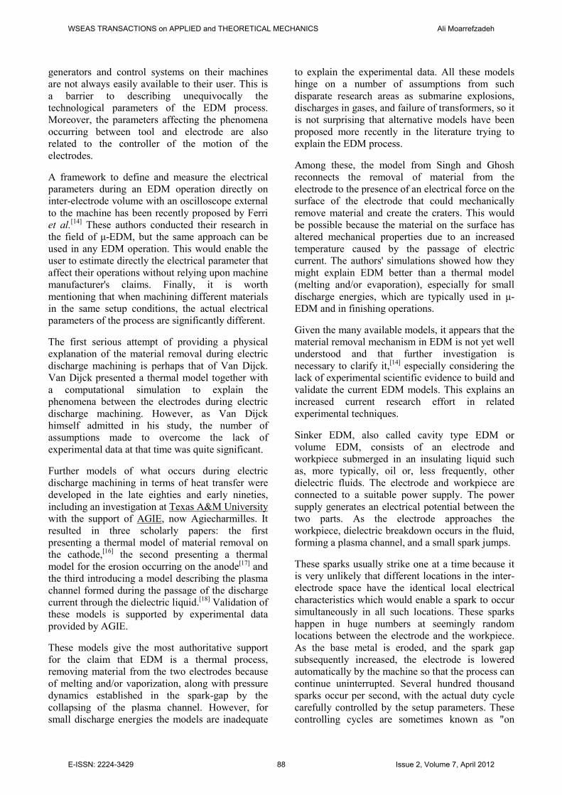
Material removal in EDM mainly occurs due to
intense localised heating almost by point heat source
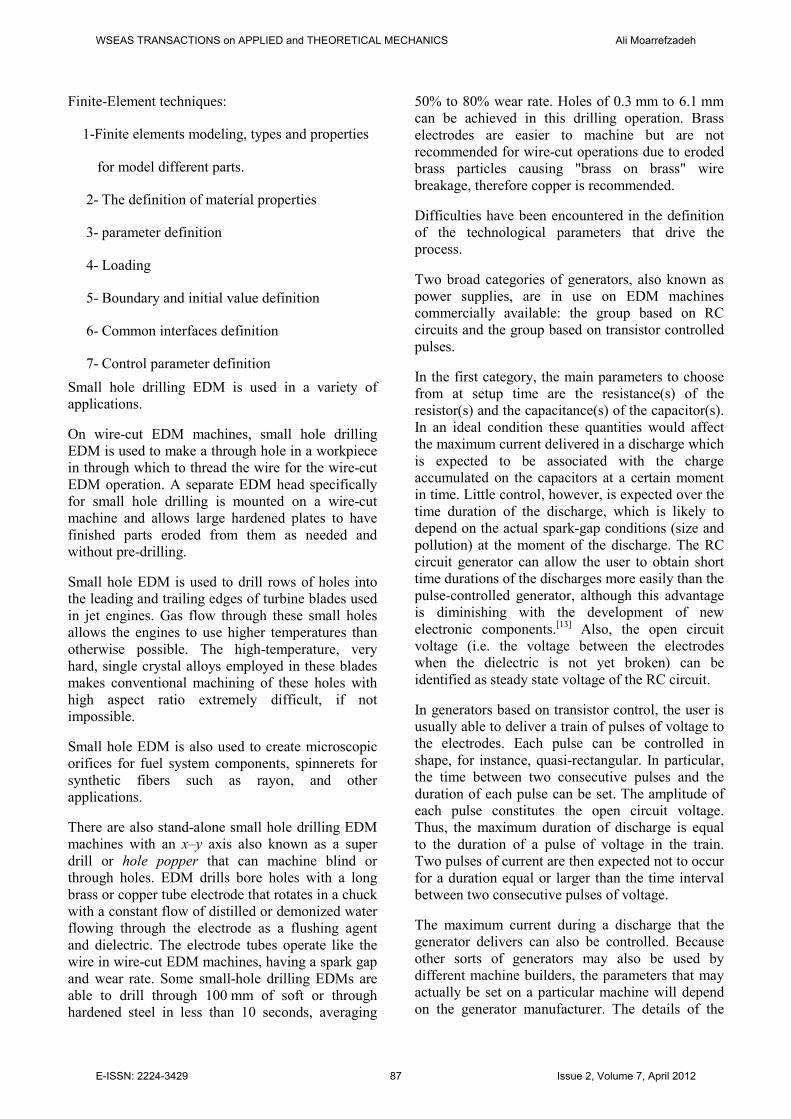
for a rather small time frame. Such heating leads to
melting and crater formation as shown in Fig. 3.
Fig.2. Comparison of experimental and predicted values
for MRR and EWR.
Fig.3. Schematic representation of crater formation in
EDM process.
WSEAS TRANSACTIONS on APPLIED and THEORETICAL MECHANICS Ali Moarrefzadeh
E-ISSN: 2224-3429 89 Issue 2, Volume 7, April 2012
The model presented above is a very simplified one
and linear relationship is not observed in practice.
But even then such simplified model captures the
complexity of EDM in a very efficient manner.
MRR in practice does increase with increase in
working voltage, current, pulse on time and
decreases with increase in pulse off time.
Product quality is a very important characteristic of
a manufacturing process along with MRR. The
followings are the product quality issues in EDM
• Surface finish
• Overcut
• Taper cut
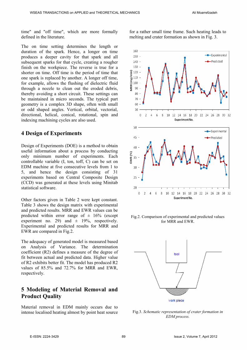
No two sparks take place side by side. They occur
completely randomly so that over time one gets
uniform average material removal over the whole
tool cross section. But for the sake of simplicity, it is
assumed that sparks occur side by side as shown in
Fig. 4.
Fig. 4 Schematic representation of the sparks in
EDM process.
Thus it may be noted that surface roughness in
EDM would increase with increase in spark energy
and surface finish can be improved by decreasing
working voltage, working current and pulse on time.
In EDM, the spark occurs between the two nearest
point on the tool and workpiece. Thus machining
may occur on the side surface as well leading to
overcut and tapercut as depicted in Fig. 5. Taper cut
can be prevented by suitable insulation of the tool.
Overcut cannot be prevented as it is inherent to the
EDM process. But the tool design can be done in
such a way so that same gets compensated.
Fig. 5 Schematic depiction of taper cut and over cut and
control of taper cut
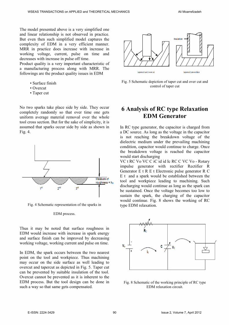
6 Analysis of RC type Relaxation
EDM Generator
In RC type generator, the capacitor is charged from
a DC source. As long as the voltage in the capacitor
is not reaching the breakdown voltage of the
dielectric medium under the prevailing machining
condition, capacitor would continue to charge. Once
the breakdown voltage is reached the capacitor
would start discharging
VC t RC Vo VC C iC id id Ic RC C VC Vo - Rotary
impulse generator with rectifier Rectifier R
Generator E t R E t Electronic pulse generator R C
E t and a spark would be established between the
tool and workpiece leading to machining. Such
discharging would continue as long as the spark can
be sustained. Once the voltage becomes too low to
sustain the spark, the charging of the capacitor
would continue. Fig. 8 shows the working of RC
type EDM relaxation.
Fig. 8 Schematic of the working principle of RC type
EDM relaxation circuit.
WSEAS TRANSACTIONS on APPLIED and THEORETICAL MECHANICS Ali Moarrefzadeh
E-ISSN: 2224-3429 90 Issue 2, Volume 7, April 2012
7 Conclusions
In this paper, the finite element method is used to
simulate the vibration assisted EDM process. The
simulation result shows that good quality surfaces
are achieved when vibration of median values of
amplitude is applied to the worktable. This is
attributed to the effect of surface tension and the
additional shear forces developed in the melted
metals by vibrating the worktable, which can
smooth the workpiece surface. The optimal
vibration conditions are found at a medium
vibration amplitude and high vibration frequency.
Therefore, vibrating the worktable during the EDM
process would be a potential solution to eliminate
the micro-craters, which are inevitable in the
conventional EDM process. A vibration system
developed to generate high frequency for the
vibration assisted EDM process is described in a
companion paper.
The following conclusions can be derived based on
the obtained results:
1. Experimental values of MRR and EWR can
satisfactorily be predicted using the developed
model by performing minimum number of
experiments.
2. Reproducibility analysis and R2 values prove that
consistent and reliable results can be achieved
within acceptable error ranges.
3. Mathematical modelling of EDM hole drilling
process using RSM technique can enable the
prediction of MRR and EWR values without
performing unnecessary experiments. This leads to
considerable savings on time, material and effort
which results in efficient, sustainable and
economical production.
References
[1] Elizabeth Ayers, Rebecca Nugent, Nema Dean,
A Comparison of Student Skill Knowledge Estimates
[2] Ryan Baker, Di erences Between Intelligent
Tutor Lessons, and the Choice to Go O -Task
[3] Dror Ben-Naim, Michael Bain, Nadine Marcus,
User-Driven and Data-Driven Approach for
Supporting teachers in Reflection and Adaptation of
Adaptive Tutorials
[4] Javier Bravo Agapito, Alvaro Ortigosa,
Detecting Symptoms of Low Performance Using
Production Rules
[5] Gerben Dekker, Mykola Pechenizkiy, Jan
Vleeshouwers, Predicting Students Drop Out: A
Case Study
[6] Mingyu Feng, Joseph Beck, Neil He ernan,
Using Learning Decomposition and Bootstrapping
with Randomization to Compare the Impact of Di
different Educational Interventions on Learning
[7] Yue Gong, Dovan Rai, Joseph Beck, Neil He
ernan, Does Self-Discipline impact students'
knowledge and learning
[8] Arnon Hershkovitz, Ra Nachmias, Consistency
of Students' Pace in Online Learning
[9] Tara Madhyastha, Steven Tanimoto, Student
Consistency and Implications for Feedback in
Online Assessment Systems
[10] Ryo Nagata, Keigo Takeda, Koji Suda, Junichi
Kakegawa, Koichiro Morihiro, Edu-mining for Book
Recommendation for Pupils
[11] Rebecca Nugent, Elizabeth Ayers, Nema Dean,
Conditional Subspace Clustering of Skill Mastery:
Identifying Skills that Separate Students
[12] Zachary Pardos, Neil He ernan, Determining
the Significance of Item Order In Randomized
Problem Sets
WSEAS TRANSACTIONS on APPLIED and THEORETICAL MECHANICS Ali Moarrefzadeh
E-ISSN: 2224-3429 91 Issue 2, Volume 7, April 2012
[13] Philip I Pavlik Jr., Hao Cen, Kenneth R.
Koedinger, Learning Factors Transfer Analysis:
Using Learning Curve Analysis to Automatically
Generate Domain Models
[14] David Prata, Ryan Baker, Evandro Costa,
Carolyn Rose, Yue Cui, Detecting and
Understanding the Impact of Cognitive and
Interpersonal Conflict in Computer Supported
Collaborative Learning Environments
[15] Dovan Rai, Yue Gong, Joseph Beck, Using
Dirichlet priors to improve model parameter
plausibility
[16] Steven Ritter, Thomas Harris, Tristan Nixon,
Daniel Dickison, R. Charles Murray, Brendon
Towle, Reducing the Knowledge Tracing Space
[17] Vasile Rus, Mihai Lintean, Roger Azevedo,
Automatic Detection of Student Mental Models
During Prior Knowledge Activation in MetaTutor
[18] MariWan WSimko, Maria Bielikova, Automatic
Concept Relationships Discovery for an Adaptive E-
course
[19] John Stamper, Ti any Barnes, An unsupervised,
frequency-based metric for selecting hints in an
MDP-based tutor
[20] Cesar Vialardi Sacin, Javier Bravo Agapito,
Leila Shafti, Alvaro Ortigosa, Recommendation in
Higher Education Using Data Mining Techniques
WSEAS TRANSACTIONS on APPLIED and THEORETICAL MECHANICS Ali Moarrefzadeh
E-ISSN: 2224-3429 92 Issue 2, Volume 7, April 2012


![SIMULATION STUDIES OF IMPACT OF ELECTRODE ... no direct contact between tool and workpiece. In general, EDM is machined with single spark discharge. Dibitonto et al. [1] used a point](https://static.fdocuments.in/doc/165x107/5b0e1f307f8b9abc0a8eadfa/simulation-studies-of-impact-of-electrode-no-direct-contact-between-tool-and.jpg)