Study of the Magnetic Field of a Permanent Magnet ...anale-ing.uem.ro/2016/9.pdf · 73 Study of the...
16
73 Study of the Magnetic Field of a Permanent Magnet Synchronous Generator by using the Finite Element Method Constantin Gabriel Dobrean, Marius Biriescu, Marțian Moț, Gheorghe Madescu, Marian Greconici The study shows the numerical simulation of the magnetic field for a permanent magnet synchronous generator prototype. Through the study, the OPERA software environment, a program based on the nu- merical computation using the finite element method and used for the virtual simulation of the synchronous generator prototype, is shown. This 5 kVA power, permanent magnet and low speed prototype is meant for uses in hydraulic driven applications, namely wind applica- tions, and was performed within a cooperations between the Faculty of Automation and Computers and the Faculty of Electrical and Power En- gineering within the “Politehnica” University of Timișoara. Keywords: synchronous generator, permanent magnets, magnetic field, finite element method. 1. Introduction Worldwide discussions and concerns have been recently focused and now tend to new approaches and regulations to reduce the use of fossil fuels as a main source for the electricity generation, its main inconveniences being the air pollution and the fact that those resources are exhaustible over time, but to satisfy the fur- ther electricity needs. To this end, during the latest years a special importance has been granted to the research and implementation of the electricity alternative con- version systems based on renewable energies such as wind, solar, hydraulic, geo- thermal or biomass energies [1]. The price reduction of rare-earth permanent magnets, particularly the NdFeB ones, as well as their very good properties have had a significant contribution to the application development as regards the building of electric generators [2]. From the structural point of view, this synchronous generator is formed of the stator contain- ANALELE UNIVERSITĂŢII “EFTIMIE MURGU” REŞIŢA ANUL XXIII, NR. 1, 2016, ISSN 1453 - 7397
Transcript of Study of the Magnetic Field of a Permanent Magnet ...anale-ing.uem.ro/2016/9.pdf · 73 Study of the...
73
Study of the Magnetic Field of a Permanent Magnet Synchronous Generator by using the Finite Element Method
Constantin Gabriel Dobrean, Marius Biriescu, Marțian Moț, Gheorghe Madescu, Marian Greconici
The study shows the numerical simulation of the magnetic field for a permanent magnet synchronous generator prototype. Through the study, the OPERA software environment, a program based on the nu-merical computation using the finite element method and used for the virtual simulation of the synchronous generator prototype, is shown. This 5 kVA power, permanent magnet and low speed prototype is meant for uses in hydraulic driven applications, namely wind applica-tions, and was performed within a cooperations between the Faculty of Automation and Computers and the Faculty of Electrical and Power En-gineering within the “Politehnica” University of Timișoara.
Keywords: synchronous generator, permanent magnets, magnetic field, finite element method.
1. Introduction
Worldwide discussions and concerns have been recently focused and now tend to new approaches and regulations to reduce the use of fossil fuels as a main source for the electricity generation, its main inconveniences being the air pollution and the fact that those resources are exhaustible over time, but to satisfy the fur-ther electricity needs. To this end, during the latest years a special importance has been granted to the research and implementation of the electricity alternative con-version systems based on renewable energies such as wind, solar, hydraulic, geo-thermal or biomass energies [1].
The price reduction of rare-earth permanent magnets, particularly the NdFeB ones, as well as their very good properties have had a significant contribution to the application development as regards the building of electric generators [2]. From the structural point of view, this synchronous generator is formed of the stator contain-
ANALELE UNIVERSIT ĂŢII
“EFTIMIE MURGU” RE ŞIŢA
ANUL XXIII, NR. 1, 2016, ISSN 1453 - 7397

74
ing 33 slots where there are the three-phase coils and the rotor on which 32 per-manent magnets are placed. That structural variant has the advantage of the gen-erator coupling directly to the turbine shaft, and thus the use of the speed multiplier is not necessary any longer, and therefore advantages arise such as increase of efficiency and of the electricity conversion output, reliability increase, noise and vi-bration intensity decrease [3], [4]. Another important advantage is the loss of the exciting coil, so that the decrease of the pole pitch is possible. The driving speed is reduced by the direct generator drive, and therefore the use of a large number of magnetic poles is required to increase the frequency and voltage [5], [6].
2. OPERA software environment
The technology development and the mankind progress are based on a very important consideration, namely the engineering computation which is a major component of the design process. The design represents a creative activity involv-ing multidisciplinary knowledge mainly aimed at getting the best possible system for a set of accurately imposed requirements. Together with them, computation procedures and advanced software have developed, which nowadays are essential in the design and testing processes.
Through years, but mostly during the latest two decades, numerous programs for the computer-aided design (CAD) and for the numerical simulation of the de-signed structures have been designed, many of those programs relying on the FEM (Finite Element Method) concept [7]. One of those programs is Opera, software used for the numerical analysis of the magnetic field of that permanent magnet synchronous generator. Opera represents a complex program which can be used for a wide range of applications, not only for those related to the electromagnetic analysis, for running both in the 2D module, as well as in the 3D module, both based on the finite element method [8]. The region of interest for the finite ele-ment is the meshes. As the element number is limited and must be finite, the meshes must have an external boundary. That boundary requires “limiting condi-tions” or “boundary conditions”. There are three main conditions required [9]:
• the first boundary condition is required when the magnetic field is en-
closed in the model and represents the most frequent case; in this case the magnetic field is tangent to the external boundary;
• the second boundary condition is required when the magnetic field is per-pendicular to a boundary;
• the third case is more rarely encountered and represents the situation when the magnetic field can have any direction to the boundary.
The OPERA program was designed based on the finite element method princi-
ple, being used as an analysis tool in various engineering fields, among which the study field of the electric machinery electromagnetic field. The basic idea is the

75
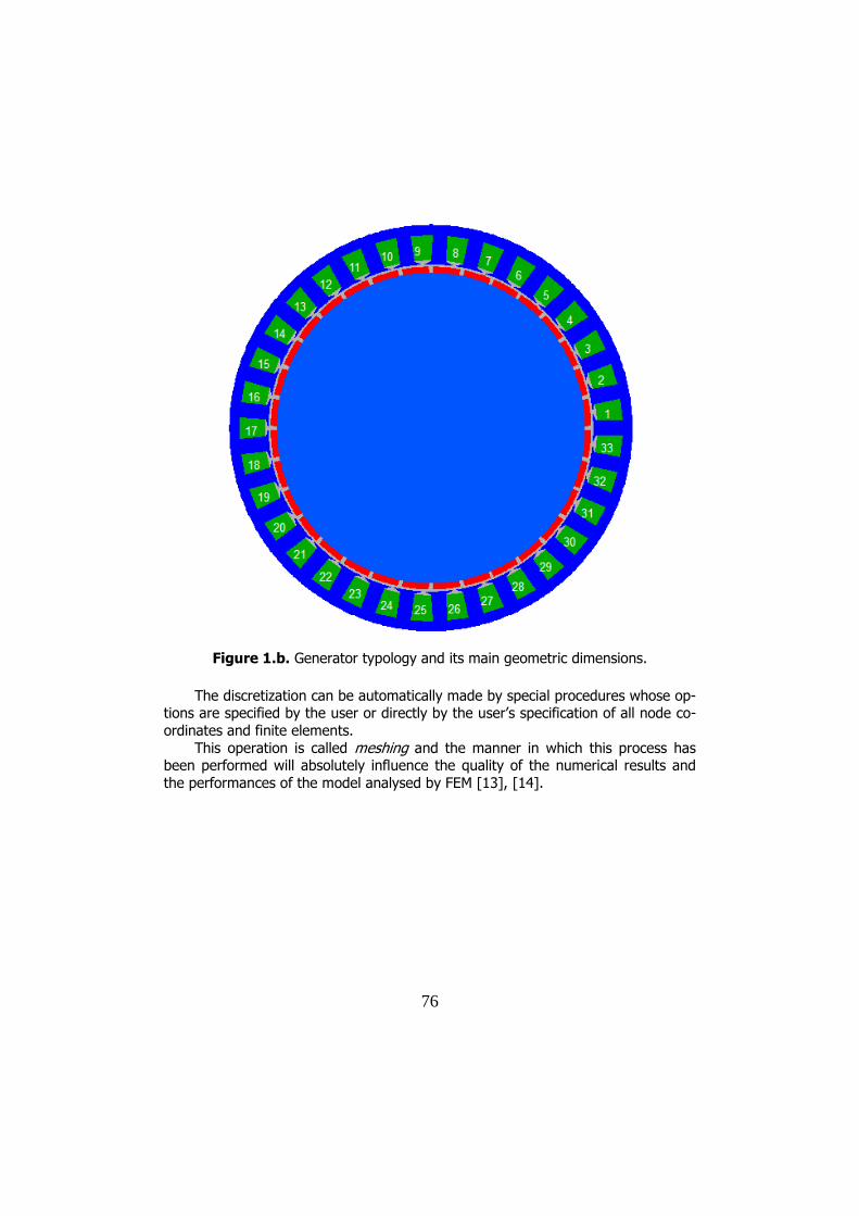
creation of a model of the actual structure to be analysed, in a pre-processor, after which the computations whose processed results can be viewed in the post-processor shall be performed [10]. Figures 1.a) and 1.b) show the synchronous genenarator model built in the pre-processor stage of the Opera program. As stated before, as regards its typology, the generator contains 33 stator slots where there are the three-phase coils and 32 NdFeB permanent magnets located on the rotor.
Figure 1.a. Generator typology and its main geometric dimensions.
For the pre-processing stage the software makes a CAD-type graphic interface
available to the user; there a draft can be created based on which the model to be analysed by the user is designed. Within that stage the following are also speci-fied: input data, material definitions, analysis type (static, dynamic, caloric, stability analysis, etc.), shape, number, type and dimensions of the finite elements used, node number, boundary conditions, including the mesh generation, namely discre-tization, the most laborious and difficult pre-process operation [11], [12].
76
Figure 1.b. Generator typology and its main geometric dimensions.
The discretization can be automatically made by special procedures whose op-
tions are specified by the user or directly by the user’s specification of all node co-ordinates and finite elements.
This operation is called meshing and the manner in which this process has been performed will absolutely influence the quality of the numerical results and the performances of the model analysed by FEM [13], [14].

77
Figure 2.a. Discretization mesh.
Figure 2.b. Discretization mesh.
78
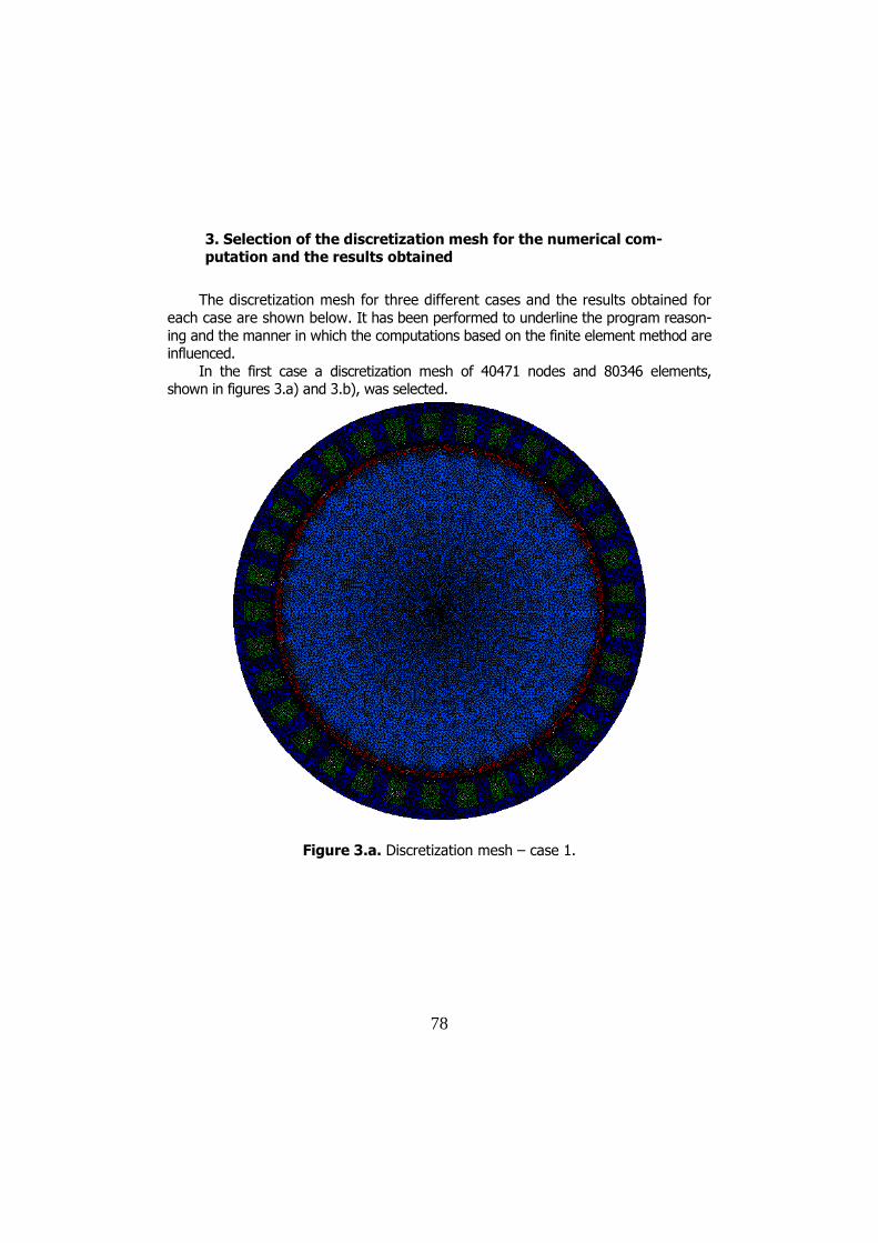
3. Selection of the discretization mesh for the numerical com-putation and the results obtained
The discretization mesh for three different cases and the results obtained for each case are shown below. It has been performed to underline the program reason-ing and the manner in which the computations based on the finite element method are influenced.
In the first case a discretization mesh of 40471 nodes and 80346 elements, shown in figures 3.a) and 3.b), was selected.
Figure 3.a. Discretization mesh – case 1.
79
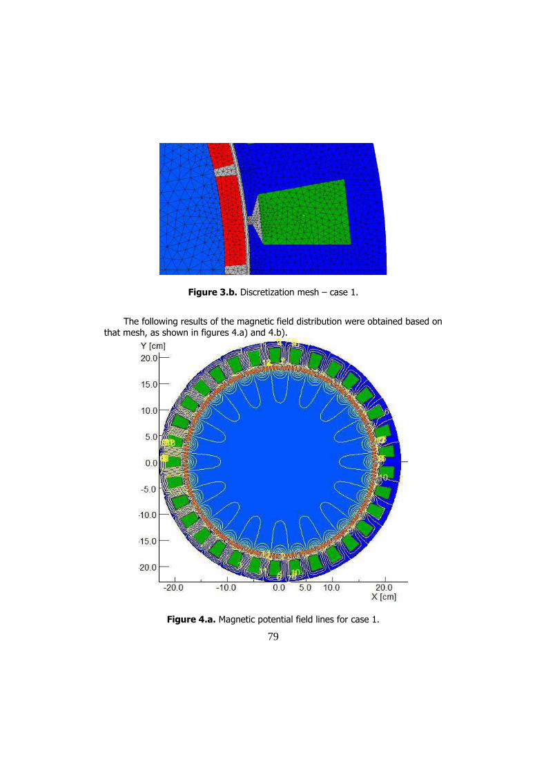
Figure 3.b. Discretization mesh – case 1.
The following results of the magnetic field distribution were obtained based on that mesh, as shown in figures 4.a) and 4.b).
Figure 4.a. Magnetic potential field lines for case 1.

80
Figure 4.b. Magnetic potential field lines for case 1.
In the second case, the selected discretization mesh is slightly more rarefied
than the first case one. In this case the mesh is formed of 28253 nodes and 56042 elements.
Figure 5. Discretization mesh for the second case.
81
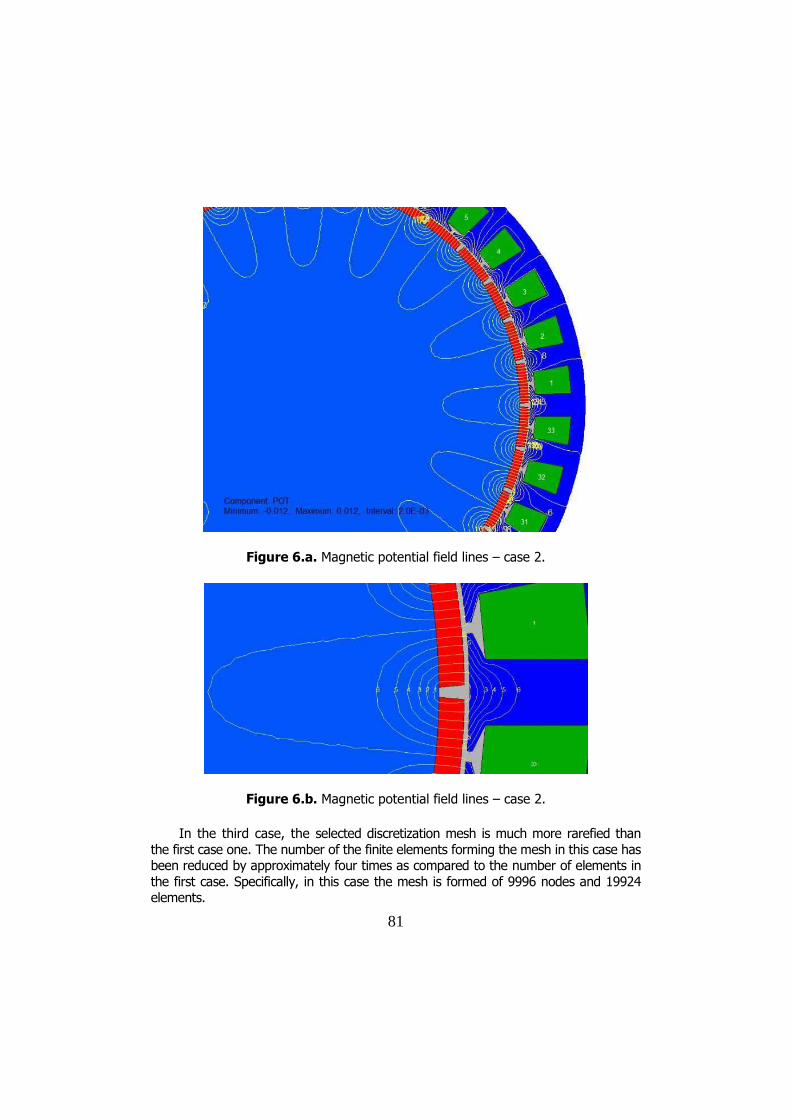
Figure 6.a. Magnetic potential field lines – case 2.
Figure 6.b. Magnetic potential field lines – case 2.
In the third case, the selected discretization mesh is much more rarefied than
the first case one. The number of the finite elements forming the mesh in this case has been reduced by approximately four times as compared to the number of elements in the first case. Specifically, in this case the mesh is formed of 9996 nodes and 19924 elements.

82
Figure 7.a. Discretization mesh for the third case.
Figure 7.b. Discretization mesh for the third case.
83
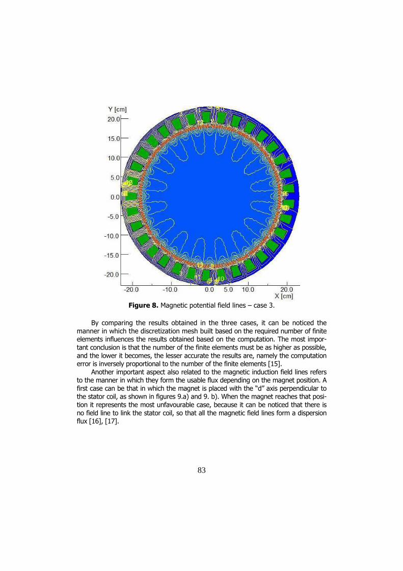
Figure 8. Magnetic potential field lines – case 3.
By comparing the results obtained in the three cases, it can be noticed the
manner in which the discretization mesh built based on the required number of finite elements influences the results obtained based on the computation. The most impor-tant conclusion is that the number of the finite elements must be as higher as possible, and the lower it becomes, the lesser accurate the results are, namely the computation error is inversely proportional to the number of the finite elements [15].
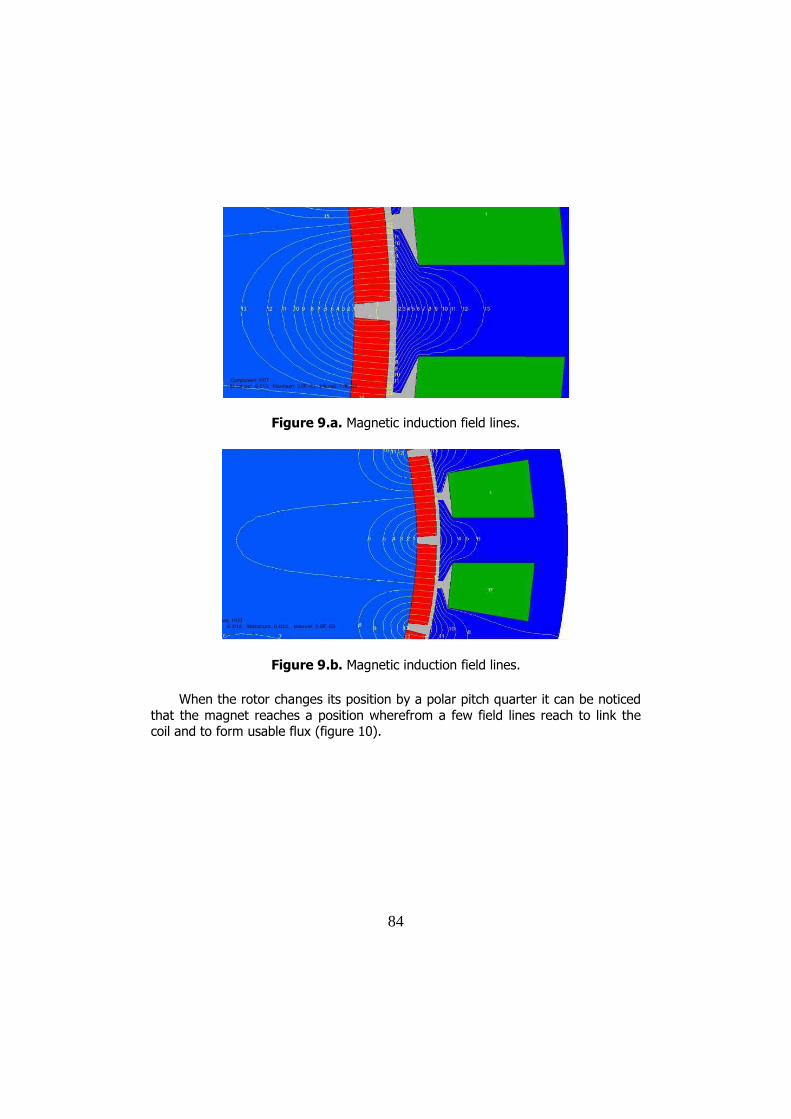
Another important aspect also related to the magnetic induction field lines refers to the manner in which they form the usable flux depending on the magnet position. A first case can be that in which the magnet is placed with the “d” axis perpendicular to the stator coil, as shown in figures 9.a) and 9. b). When the magnet reaches that posi-tion it represents the most unfavourable case, because it can be noticed that there is no field line to link the stator coil, so that all the magnetic field lines form a dispersion flux [16], [17].
84
Figure 9.a. Magnetic induction field lines.
Figure 9.b. Magnetic induction field lines.
When the rotor changes its position by a polar pitch quarter it can be noticed
that the magnet reaches a position wherefrom a few field lines reach to link the coil and to form usable flux (figure 10).
85
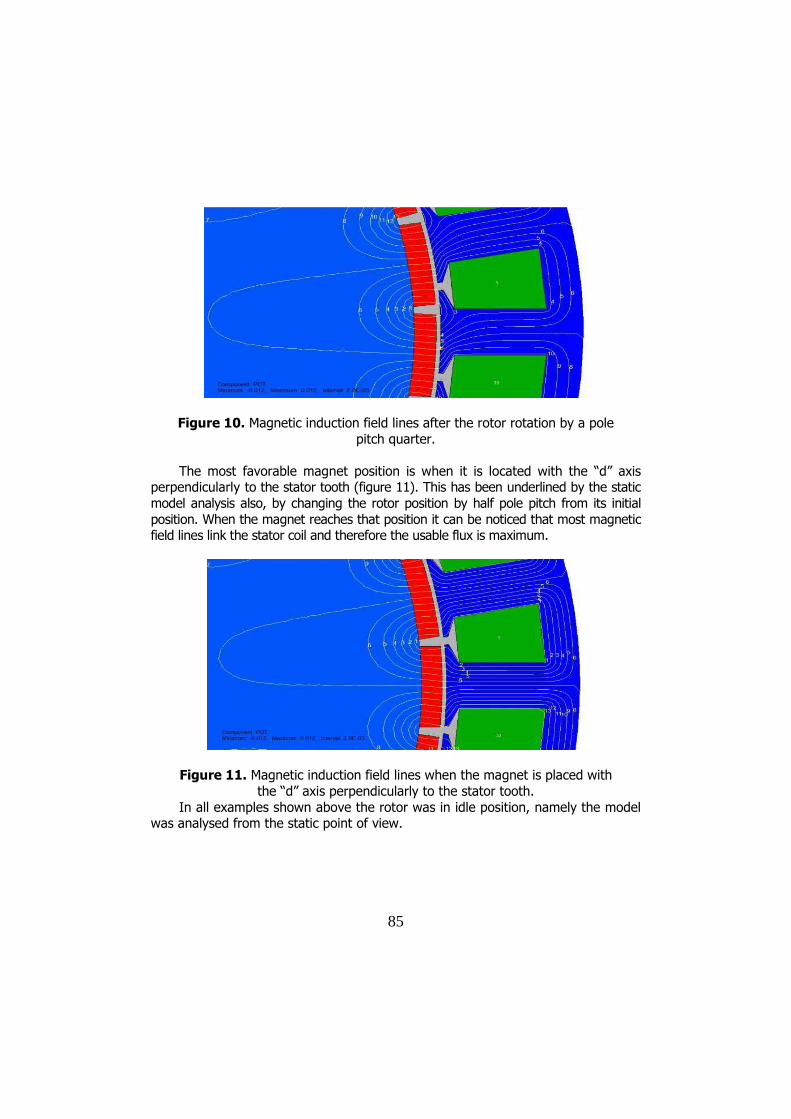
Figure 10. Magnetic induction field lines after the rotor rotation by a pole pitch quarter.
The most favorable magnet position is when it is located with the “d” axis
perpendicularly to the stator tooth (figure 11). This has been underlined by the static model analysis also, by changing the rotor position by half pole pitch from its initial position. When the magnet reaches that position it can be noticed that most magnetic field lines link the stator coil and therefore the usable flux is maximum.
Figure 11. Magnetic induction field lines when the magnet is placed with the “d” axis perpendicularly to the stator tooth.
In all examples shown above the rotor was in idle position, namely the model was analysed from the static point of view.

86
4. Conclusion
The main purpose of this study was the numerical analysis of the magnetic field of a permanent magnet synchronous generator by using the finite element method.
Another purpose was the inurement to use CAD-type tools and the assimila-tion of stages to be met when a program based on the finite element method is used: question stating, symmetry selection (parallel plane or median plane), type of the nu-merical model for the most accurate simulation of the actual structure analysed, equalization of the numerical model non-route domains to the proper material proper-ties, setting of sources and of the boundary conditions, boundary selection of the do-main to be analysed so as not to significantly change the field in the interest points, setting of the finite element shape and of the discretization mesh density, selection of the proper “solver” to obtain solutions, use of the facilities offered by the post-processor depending on the purpose of the numerical simulation.
After the generator simulation was performed, a static type analysis has been carried out. The field line shape of the magnetic induction generated by the generator permanent magnets has been obtained after the static analysis. The following were monitored: magnetic field line shape, magnetic field intensity depending on the rotor position and manner in which the number of the discretization mesh elements influ-ence the problem solution accuracy. Three cases for various discretization meshes were analysed, and by comparing the results obtained, it could be noticed the manner in which the discretization mesh built based on the required number of finite elements influenced the results. The conclusion of this analysis is that the number of the finite elements must be as higher as possible, and the lower it becomes, the lesser accurate the results are, namely the computation error is inversely proportional to the number of the finite elements.
Another important aspect also related to the magnetic induction field lines re-fers to the manner in which they form the usable flux depending on the magnet posi-tion. It has been noticed that the most favourable moment is when the permanent magnet is placed with the “d” axis perpendicularly to the stator coil, the usable flux being maximum in this case. When the rotor is rotated by half pole pitch, the “d” axis of the magnet reaches the position between the stator slots, and this is the most unfa-vourable case, because it has been noticed that no field line links the stator coil and therefore all magnetic field lines form dispersion flux only [18][19].
References
[1] Sobor I., Kobîleațkii N., Tendințe moderne în tehnologia de conversie a energiei eoliene și a energiei cinetice a curenților de apa, Universitatea Tehnica a Moldovei.
[2] Boldea I., Synchronous Generators, CRC Taylor & Francis, 2005.

87
[3] Madescu G., Biriescu M., Greconici M., Moț M., Low Speed PM Generator for Wind Turbines Applications, “Politehnica” University of Timișoara and Romanian Academy – Timișoara Branch, Timișoara, Romania.
[4] Mușuroi S., Șorândaru C., Șurianu D.F., The modeling and simulation of an adjusting system for the position of the induction machine supplied by a PWM inverter with the identification of the rotor flux, EPE Iași 12-14, Oct. 2006.
[5] Biriescu M., Transformatoare și mașini electrice, Timișoara, Editura “Ori-zonturi universitare”, 2009.
[6] Madescu G., Biriescu M., Proștean O., Mihuț T., Greconici M., Moț M., Augustinov L., Low Speed Synchronous Generator with PM Excitation.
[7] Steele C.W., Numerical computation of electric and magnetic fields, New York, Van Nostrand Reinhold Company, 1987.
[8] “Opera – Manager user guide”, Version 12.025, Vector Fields, Oxford, 2008.
[9] “Opera 2D – Reference Manual”, Version 12.025, Vector Fields, Oxford, 2008.
[10] “Opera 2d – User Guide”, Version 12, Kidlington - Oxford, 2008. [11] Lowther D.A., Silvester P.P., Computer- Aided Design in Magnetics, New
York, Springer-Verlag, 1986. [12] Comșa D.S., Metoda elementelor finite- Curs introductiv, Cluj-Napoca,
Editura U.T. PRES, 2007. [13] Sorohan Şt., Constantinescu I.N., Practica modelarii și analizei cu
elemente finite, București, 2003. [14] Sorohan Şt., Petre C.C., Programe și aplicații cu elemente finite,
București, Editura PRINTECH, 2004 (revizuita Sept. 2007). [15] Madescu G., Biriescu M., Greconici M., Moț M., Performances comparison
of two surface-mounted Permanent Magnet Generators with fractional - slot windings, International Review of Electrical Engineering (I.R.E.E.), Vol. xx, n.x.
[16] Fitzgerald A.E., Electric machinery (sixth edition), New York, The McGraw – Hill Companies, 1989.
[17] Madescu G., Biriescu M., Moț M., Greconici M., Koch C., Low Speed PM Generator for Direct-Drive Wind Applications, “Politehnica” University of Timișoara and Romanian Academy – Timișoara Branch, Timişoara.
[18] Biriescu M., Mașini Electrice Rotative, Timișoara, Editura de Vest, 1997. [19] Boldea I., Transformatoare și mașini electrice, Timișoara, Editura
“Politehnica”, 2010.

88
Addresses:
• Phd. student Eng. Constantin Gabriel Dobrean, “Politehnica” University of Timisoara, Vasile Parvan Bd., no. 2, RO-300223, Timisoara, [email protected]
• Prof. Dr. Eng. Marius Biriescu, “Politehnica” University of Timisoara, Vasile Parvan Bd., no. 2, 300223, Timisoara, [email protected]
• Dr. Eng. Martian Mot, “Politehnica” University of Timisoara, Vasile Par-van Bd., no. 2, 300223, Timisoara, [email protected]
• Dr. Eng. Gheorghe Madescu, Romanian Academy - Timisoara Branch, Timisoara, Romania, [email protected]
• Conf. Dr. Eng. Marian Greconici, “Politehnica” University of Timisoara, Vasile Parvan Bd., no. 2, 300223, Timisoara, [email protected]