
Study of sol-gel derived di-ureasils doped with zinc triflate
22
Solid State Sciences 1 S. C. Nunes et al. Study of sol-gel derived di-ureasils doped with zinc triflate S. C. Nunes a , V. de Zea Bermudez a * , M. M. Silva b , M. J. Smith b , E. Morales c , R. A. Sá Ferreira d , L. D. Carlos d , J. Rocha e a Departamento de Química and CQ-VR, Universidade de Trás-os-Montes e Alto Douro 5000-911 Vila Real, Portugal b Departamento de Química, Universidade do Minho, Gualtar, 4710-057 Braga, Portugal c Instituto de Ciencia y Tecnología de Polímeros (CSIC), Calle Juan de la Cierva 3, 28006 Madrid, Spain d Departamento de Física and CICECO, Universidade de Aveiro, 3810-193 Aveiro, Portugal e Departamento de Química and CICECO, Universidade de Aveiro, 3810-193 Aveiro, Portugal Abstract Zinc triflate (Zn(CF 3 SO 3 ) 2 )-doped sol-gel derived di-urea cross-linked POE/siloxane ormolytes (designated as di-ureasils) with ∞ > n ≥ 1 (where the salt content is expressed as n, the molar ratio of oxyethylene moieties to Zn 2+ ions) were investigated. The hybrids with n ≥ 5 are entirely amorphous; those with n > 10 are thermally stable up to approximately 305 ºC. The siliceous network of representative samples (n = 200 and 10) is essentially composed of (SiO) 3 Si(CH 2 )- environments and is thus highly branched. The distance between the structural units in samples with 200 ≥ n ≥ 10 and n ≤ 7 is 4.2 and 4.3 Å, respectively. The estimated interdomain distance is 11 and 13 Å for xerogels with 200 ≥ n ≥ 20 and n ≤ 10, respectively. At n = 1 a crystalline POE/Zn(CF 3 SO 3 ) 2 complex of unknown stoichiometry is formed. The conductivity maxima are located at n = 60 (3x10 -6 S cm -1 ) and n = 20 (7x10 -5 S cm -1 ) at 30 and 100 ºC, respectively. Keywords: POE/siloxane, di-ureasils, zinc triflate, ionic conductivity * Corresponding author. Tel: +351-259-350253; Fax: +351-259-350480; E-mail address: [email protected]
Transcript of Study of sol-gel derived di-ureasils doped with zinc triflate

Solid State Sciences 1 S. C. Nunes et al.
Study of sol-gel derived di-ureasils doped with zinc triflate
S. C. Nunesa, V. de Zea Bermudeza*, M. M. Silvab, M. J. Smithb, E. Moralesc, R. A. Sá
Ferreirad, L. D. Carlosd, J. Rochae
aDepartamento de Química and CQ-VR, Universidade de Trás-os-Montes e Alto Douro
5000-911 Vila Real, Portugal
bDepartamento de Química, Universidade do Minho, Gualtar, 4710-057 Braga, Portugal
cInstituto de Ciencia y Tecnología de Polímeros (CSIC), Calle Juan de la Cierva 3, 28006 Madrid, Spain
dDepartamento de Física and CICECO, Universidade de Aveiro, 3810-193 Aveiro, Portugal
eDepartamento de Química and CICECO, Universidade de Aveiro, 3810-193 Aveiro, Portugal
Abstract Zinc triflate (Zn(CF3SO3)2)-doped sol-gel derived di-urea cross-linked POE/siloxane
ormolytes (designated as di-ureasils) with ∞ > n ≥ 1 (where the salt content is expressed as n,
the molar ratio of oxyethylene moieties to Zn2+ ions) were investigated. The hybrids with n ≥
5 are entirely amorphous; those with n > 10 are thermally stable up to approximately 305 ºC.
The siliceous network of representative samples (n = 200 and 10) is essentially composed of
(SiO)3Si(CH2)- environments and is thus highly branched. The distance between the structural
units in samples with 200 ≥ n ≥ 10 and n ≤ 7 is 4.2 and 4.3 Å, respectively. The estimated
interdomain distance is 11 and 13 Å for xerogels with 200 ≥ n ≥ 20 and n ≤ 10, respectively.
At n = 1 a crystalline POE/Zn(CF3SO3)2 complex of unknown stoichiometry is formed. The
conductivity maxima are located at n = 60 (3x10⁻⁶ S cm-1) and n = 20 (7x10⁻⁵ S cm-1) at 30
and 100 ºC, respectively.
Keywords: POE/siloxane, di-ureasils, zinc triflate, ionic conductivity
* Corresponding author. Tel: +351-259-350253; Fax: +351-259-350480; E-mail address: [email protected]

Solid State Sciences 2 S. C. Nunes et al.
1. Introduction
In the field of solid polymer electrolytes (SPEs) the hybrid concept [1], which is
intimately associated with the sol-gel process [2-5], is one of the most attractive strategies that
may be adopted to modify the architecture of poly(oxyethylene) (henceforth abbreviated as
POE). In this domain the synthesis of POE/siloxane hybrid structures is achieved through the
sol-gel strategy, with the objective of reducing the drawbacks of poor processability, a
marked tendency to form crystalline regions and the occurrence of “salting out” at high guest
salt concentrations [6]. These are some of the most important disadvantages of the classical
POE/salt electrolytes that have severely hindered their practical application in solid-state
electrochemical devices.
The sol-gel method is a versatile chemical synthetic route that permits the production,
under mild reaction conditions, of ormolytes (organically modified silicate electrolytes).
Relevant properties of novel electrolytes which may be “tailored” include specific density,
thermal stability and mechanical properties. Ormolytes based on these materials are readily
shaped into thin films and have an essentially amorphous character. Owing to their potential
application in primary and secondary advanced batteries, the Li+-doped POE/siloxane
ormolytes have been very extensively investigated [7-16]. Alkaline [17-18], alkaline-earth
[19-21] and lanthanide [22-26] metal ions have also been introduced into this class of sol-gel
derived host matrices.
In spite of its low electrode potential (-0.76 V versus NHE), zinc is considered to be a
good candidate for the fabrication of rechargeable solid-state batteries. This element is
abundant in nature, non-toxic, very stable and can be handled safely in oxygen and humid
atmospheres and thus hazards in open air are minimized. Zinc-based devices have also
relatively high specific and volumetric energy densities. Over the last few years, the
technology of rechargeable alkaline manganese oxide/zinc batteries has progressed rapidly
[27, 28]. The number of reports referring to electrolytes formed with POE and zinc salts is,

Solid State Sciences 3 S. C. Nunes et al.
however, relatively low [29-33]. Although zinc perchlorate has been incorporated into POE
[29], the most widely studied POE-based systems include those formed by the dissolution of
halogen zinc salts (ZnX2, where X= Cl [30-32], Br [31,32], I [30,31]) in the polymer host. Gel
polymer electrolytes (GPEs) composed of poly(vinylidenefluoride) (PVDF) [34] or
poly(methylmethacrylate) (PMMA) [35], plasticized with propylene carbonate and ethylene
carbonate and doped with Zn(CF3SO3)2 have also been characterized.
In the present study we have examined a new family of sol-gel derived di-urea cross-
linked POE/siloxane ormolytes (designated as di-ureasils [36,37]) incorporating Zn(CF3SO3)2.
To the best of our knowledge this is the first time that Zn2+-doped hybrid electrolytes have
been synthesized and their structure, morphology, thermal properties and ionic conductivity
have been reported. In the di-ureasil host matrix employed, designated as d-U(2000) (where d
stands for di, U denotes the urea group and 2000 is the average molecular weight of the
starting organic precursor, which corresponds to about 40.5 oxyethylene repeat units), the
extraordinary ability of the POE segments to dissolve guest salt species is combined with the
chemical, mechanical and thermal stability of the siliceous network. In addition, the d-
U(2000) framework is only slightly hygroscopic and remains amorphous even at extremely
high salt contents [16,20]. Since Berthier et al. [38] demonstrated that ion conduction
occurred exclusively in the amorphous regions of electrolytes, research in this domain has
been directed almost exclusively towards SPE systems devoid of crystalline domains.
Although very recent data obtained by Gadjourova et al. [39] suggest that ionic conductivity
in the crystalline fraction of the polymer phase can be significantly higher than in the
amorphous regions, most of the research currently performed in this field continues to be
directed toward the characterization of entirely amorphous materials.

Solid State Sciences 4 S. C. Nunes et al.
2. Experimental
2.1. Synthesis
Zn(CF3SO3)2 (Aldrich) and O,O'-Bis(2-aminopropyl) polypropylene glycol-block-
polyethylene glycol-block-polypropylene glycol (commercially designated as Jeffamine ED-
2001®, Fluka, average molecular weight 2001 g/mol) were dried under vacuum at 25 ºC for
several days prior to being used. 3-isocyanatepropyltriethoxysilane (ICPTES, Fluka) was used
as received. Ethanol (CH3CH2OH, Merck) and tetrahydrofuran (THF, Merck) were stored
over molecular sieves. High purity distilled water was used in all experiments.
The Zn(CF3SO3)2-based di-ureasils were prepared according to the method described in
detail elsewhere for the Li+ - based analogues [16]. In agreement with the terminology
adopted previously [16,20,21,23], the xerogels have been identified by the notation d-
U(2000)nZn(CF3SO3)2. The Zn(CF3SO3)2 content of samples and other relevant information
are collected in Table 1.
2.2. Characterization
29Si magic-angle spinning (MAS) and 13C cross-polarization (CP) MAS NMR spectra were
recorded on a Bruker Avance 400 (9.4 T) spectrometer at 79.49 and 100.62 MHz,
respectively. 29Si MAS NMR spectra were recorded with 2 µs (θ ≈30 º) rf pulses, and recycle
delay of 60 s and at a 5.0 kHz spinning rate. 13C CP/MAS NMR spectra were recorded with 4
µs 1H 90º pulse, 2 ms contact time, a recycle delay of 4 s and at a spinning rate of 8 kHz.
Chemical shifts (δ) are quoted in ppm from tetramethylsilane (TMS). To analyse
quantitatively the peaks observed in the 29Si MAS NMR spectra, the iterative least-squares
curve-fitting procedure in the PeakFit software (Jandel Corporation, 2591 Rerner Boulevard,
San Rafael, CA 94901, USA) was used. The best fit of the experimental data was sought by
varying the frequency, bandwidth and intensity of the peaks and by employing Voigt band

Solid State Sciences 5 S. C. Nunes et al.
shapes (a mixture of Lorentzian and Gaussian contributions). The standard errors of the
curve-fitting procedure were less than 0.01.
Differential Scanning Calorimetric (DSC) measurements were obtained in a DSC131
Setaram DSC. Disk sections with masses of approximately 20 mg were removed from the
ormolyte, placed in 40 µl aluminium cans and stored in a dessicator over phosphorous
pentoxide (P2O5) for one week at room temperature under vacuum. After this drying treatment
the cans were hermetically sealed and the thermograms were recorded. Each sample was
heated from 25 to 300 ºC at 10 C min-1. The purge gas used in all experiments was high purity
nitrogen (N2) supplied at a constant 35 cm3 min-1 flow rate.
The X-ray diffraction (XRD) patterns were recorded at room temperature with a Rigaku
Geigerflex D/max-c diffractometer system using monochromated CuKα radiation (λ = 1.541
Å) over the 2θ range of between 10 and 80 º and at a resolution of 0.05 º. The samples were
analyzed as powders and were not submitted to any thermal pre-treatment.
Samples for thermogravimetric studies (materials with n = 200, 60, 40, 20, 10, 5 and 1)
were transferred to open platinum crucibles and analyzed using a Rheometric Scientific TG
1000 thermobalance at a heating rate of 10ºC min-1 using dry N2 as purging gas (20 cm3min-1).
Prior to measurement, the xerogels were vacuum-dried at 80 ºC for about 48 h and stored in
an argon-filled glove box.
The total ionic conductivity of materials was determined by locating an ormolyte disk
between two 10 mm diameter ion-blocking gold electrodes (Goodfellow, > 99.9%). Prior to
characterization, the di-ureasil ormolytes were vacuum-dried at 80 ºC for about 48 h and
stored in an argon-filled glove box. The electrode/ormolyte/electrode assembly was secured in
a suitable constant-volume support [40] which was installed in a Buchi TO 51 tube oven. A
calibrated type K thermocouple, placed close to the ormolyte disk, was used to measure the
sample temperature with a precision of about 0.2 ºC and samples were characterized over a
temperature range of between 25 and 100 ºC. Bulk conductivities of the samples were

Solid State Sciences 6 S. C. Nunes et al.
obtained during heating cycles using the complex plane impedance technique (Schlumberger
Solartron 1250 frequency response analyser and 1286 electrochemical interface) over a
frequency range of 65 kHz to 0.5 Hz. The electrolyte behaviour was found to be almost ideal
and bulk conductivities were extracted in the conventional manner from impedance data.
Reproducibility of measurements was better than 5%.
3. Results and Discussion
3.1. Structure and Morphology
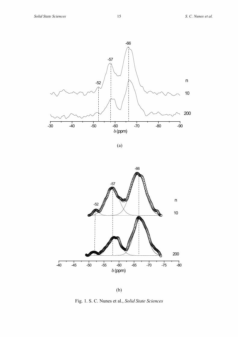
The 29Si MAS NMR spectra of Zn2+-based di-ureasils with n = 200 and 10 exhibit three
signals at -52, -58 and -66 ppm (Fig. 1). On the basis of the conventional Tm silicon (Si)
notation (where m* = 1, 2 and 3 represents the number of Si atoms bonded to O-Si units)
these resonances are ascribed to T1, T2 and T3 sites, respectively (Table 2). The relative
population of the three Si environments demonstrates that in both samples the dominating
environment is T3 (Table 2), meaning that under the experimental conditions applied the
condensation reactions favoured the growth of branched structures. The degrees of
polycondensation c reported in Table 2 are significantly higher than those observed in the
non-doped framework (75%) [41]. On the basis of the empirical formula deduced for the two
xerogels (Table 2), which suggest that a few terminal OCH2CH3 or OH groups persist bonded
to the Si atoms, we propose that these composites have the idealized structure (Scheme 1).
The diffractograms of the Zn(CF3SO3)2-based di-ureasils with 200 ≥ n ≥ 5 illustrated in Fig.
2 lead us to conclude that these samples are entirely amorphous. The characteristic amorphous
broad peak, Gaussian in shape and centered at approximately 21.61º in these patterns, is
attributed to the coherent diffracting regions of the siliceous network [42]. The second-order
* The conventional notation Tn has been changed to Tm, to avoid any confusion with the notation n used for salt composition throughout the text.

Solid State Sciences 7 S. C. Nunes et al.
of this peak is observed as a broad, low-intensity hump located around 40º in the XRD
patterns of the samples with 20 ≥ n ≥ 10 (Fig. 2). A structural unit distance of 4.2 and 4.3 Å
was obtained for the hybrids with 200 ≥ n ≥ 10 and n ≤ 7, respectively, using the Bragg law.
The coherent length L over which the structural unit survives in the Zn2+-doped di-ureasils
was estimated using the modified Scherrer equation L = I λ / (A cosθ), where A, in radians, is
the integrated area of the peaks and I their intensity. Coherent lengths of 11 and 13 Å were
derived for hybrids with 200 ≥ n ≥ 20 and n ≤ 10, respectively. These values of L are similar
to those reported for the non-doped di-ureasils [43]. In the XRD pattern of the hybrid with n =
1, a series of intense and sharp Bragg reflections are evident (Fig. 2). As these peaks do not
coincide with those of the pure salt, they have been attributed to a crystalline
POE/Zn(CF3SO3)2 complex of unknown stoichiometry [6].
3.2. Thermal properties
The DSC curves of the d-U(2000)nZn(CF3SO3)2 ormolytes with 200 > n > 5 (Fig. 3)
demonstrate that these materials are amorphous, a result that corroborates the XRD data. The
weak, broad endotherms centered around 150 ºC (with onset temperatures of about 75ºC) seen
in the thermograms of the concentrated samples with n = 7 and 5 (Fig. 3) are ascribed to the
evaporation of occluded solvents (water, ethanol or THF). As the d-U(2000) matrix is only
slightly hygroscopic, the presence of minor traces of water must be associated with the zinc
salt. Water from the salt-containing xerogels could be readily removed by drying the samples
under vacuum at room temperature in the presence of a P2O5. The efficiency of the drying
procedure was monitored by means of infrared spectroscopy. The profile of the OH stretching
envelope in the high-frequency region of the FT-IR spectra of the d-U(2000)nZn(CF3SO3)2
composites confirms that the amount of residual water in the samples is negligible (see Fig. 1
of Ref. 44). The origin of the set of endotherms centred around 84, 106, 160 and 177 ºC in the
DSC curve of the salt-rich xerogel with n = 1 (Fig. 3) is not clear.

Solid State Sciences 8 S. C. Nunes et al.
The TGA curves of representative Zn(CF3SO3)2-doped ormolytes with 200 ≥ n ≥ 20 and
n ≤ 10 are reproduced in Figs.4(a) and 4(b), respectively . The d-U(2000)nZn(CF3SO3)2 di-
ureasils with n ≥ 20 are thermally stable up to about 300 ºC (Fig. 4(a)), a value very close to
that reported for the non-doped matrix [16]. At about 420 ºC a mass loss was observed that
decreased with increasing salt concentration (Fig. 4(a)). In the case of the di-ureasils with n =
40 and 20 a slight mass loss was observed at around 32 ºC, probably due to solvent and water
loss. Thermal degradation in the samples with n = 10 and 5 takes places in three stages: a
slight gradual mass loss takes place around 50 ºC, followed by two abrupt changes, one at 280
and the other at 410 ºC (Fig. 4(b)). In contrast, the most concentrated compound analyzed (n =
1) suffers a marked weight loss at only 32 ºC, followed by a further event at about 300 ºC and
by an abrupt decomposition that is initiated at 500 ºC (Fig. 4(b)). The major degradation of
this d-U(2000)1Zn(CF3SO3)2 di-ureasil sample occurs in the latter stage (Fig. 4(b)). These
data allow us to assign the endotherms evident in the DSC thermograms of the salt-rich di-
ureasil (n = 1) to the coupled effect of fusion of the crystalline POE/Zn(CF3SO3)2 complex
identified by XRD (Fig. 2) and degradation reactions.
3.3 Ionic conductivity
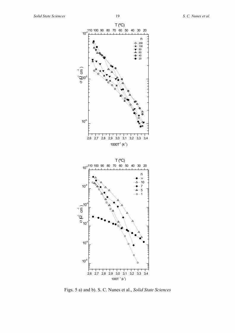
The Arrhenius conductivity plots and the graph of the conductivity isotherms of the d-
U(2000)nZn(CF3SO3)2 ormolytes with ! > n ≥ 1 are depicted in Figs. 5 and 6, respectively.
The Zn2+-doped di-ureasils with n ≥ 20 display moderate levels of ionic conductivity over the
whole range of temperatures considered (Fig. 5(a)). At 30 and 100 ºC the ormolytes with the
highest conductivity are d-U(2000)60Zn(CF3SO3)2 (2.7x10⁻⁶ S cm-1) and d-
U(2000)20Zn(CF3SO3)2 (7x10⁻⁵ S cm-1), respectively (Figs. 5(a) and 6). At higher salt
concentration (n ≤ 10) the ionic conductivity suffers a marked decrease ((Figs. 5(b) and 6).
The surprisingly low ionic conductivity exhibited by the salt-rich hybrid with n = 1 (below 60
ºC it is even lower than that of the non-doped hybrid (Fig. 5(b)), which was attributed to

Solid State Sciences 9 S. C. Nunes et al.
proton hopping between the urea groups [36,37]) correlates well with the existence of a
crystalline POE/Zn(CF3SO3)2 complex, which globally reduces the proportion of amorphous
material in the sample and consequently restricts polymer segment mobility and ion transport
[6].
At ambient temperature electrolytes produced by the sol-gel process show an
improvement over the poor conductivity typically exhibited by POE-based electrolytes. This
is a consequence of the high proportion of crystalline material present in the latter material. In
the Zn(CF3SO3)2-based di-ureasil compounds with 100 ≥ n ≥ 10 the ionic conductivity varies
from 10-6 to 10-5 S cm-1 at room temperature, whereas the conventional PEO-based solid
electrolytes yield conductivities of the order of 10-8 S cm-1 [45].
The ionic conductivity displayed by the d-U(2000)nZn(CF3SO3)2 xerogels is significantly
lower than the conductivity maxima exhibited by the Zn(CF3SO3)2-doped SPE reported by
Ikeda et al [33] (2.1x10⁻⁴ S cm-1 at room temperature for a sample containing 4 mol%
Zn(CF3SO3)2) and by the PVDF- and PMMA-based GPEs of Kumar et al. (3.94x10⁻³ S cm-1 at
25 ºC [34] and 1.3x10⁻³ S cm-1 at 27 ºC [35], respectively). GPEs are however expected to
have a greater propensity for interfacial problems than ormolytes [46]. Thus, in this sense,
sol-gel derived materials such as the ones proposed here may be a viable alternative.
4. Conclusions
Novel Zn(CF3SO3)2-doped di-ureasil ormolytes with ∞ > n ≥ 1 were synthesized by the
sol-gel process. Materials with n ≥ 5 were obtained as completely amorphous, transparent and
flexible thin monolithic films. In the compound with n = 1, produced as a white powder, a
crystalline POE/Zn(CF3SO3)2 complex of unknown stoichiometry is formed. The xerogels
with 200 > n ≥ 20 are thermally stable up to 305 ºC. At 30 and 100 ºC, the most conducting
di-ureasils are d-U(2000)60Zn(CF3SO3)2 (3x10⁻⁶ S cm-1) and d-U(2000)20Zn(CF3SO3)2 (7x10⁻⁵
S cm-1), respectively.

Solid State Sciences 10 S. C. Nunes et al.
The encouraging results obtained in the present work suggest that further studies on the
zinc-doped d-U(2000)-based di-ureasil ormolytes are worth pursuing. In particular, the
replacement of the triflate ion by a more suitable anion is expected to result in a significant
increase of the ionic conductivity values.
Acknowledgements
Financial support from the Fundação para a Ciência e Tecnologia (POCTI/P/CTM/46780/03
and SFRH/BD/13559/03) is gratefully acknowledged.
References
[1] P. Gomez-Romero, C. Sanchez (Eds), Functional Hybrid Materials, Wiley Interscience,
New York, 2003
[2] C. J. Brinker, G. W. Scherer, Sol-Gel Science: The Physics and Chemistry of Sol-Gel
Processing, Academic Press, San Diego, CA, 1990.
[3] J. D. Mackenzie, J. Sol-Gel Sci. & Technol. 26 (2003) 23.
[4] S. Sakka, J. Sol-Gel Sci. & Technol. 26 (2003) 29.
[5] U. Schubert, J. Sol-Gel Sci. & Technol. 26 (2003) 47.
[6] F. M. Gray, Polymer Electrolytes, RSC Materials Monographs, The Royal Society of
Chemistry, London, 1997.
[7] D. Ravaine, A. Seminel, Y. Charbouillot, M. Vincens, J. Non-Cryst. Solids 82 (1986) 210
[8] M. Popall, M. Andrei, J. Kappel, J. Kron, K. Olma, B. Olsowski, Electrochim. Acta, 43
(10-11) (1998) 1155.
[9] P. Judeinstein, J. Titman, M. Stamm, H. Schmidt, Chem. Mater. 6 (1994) 127.
[10] K. Dahmouche, M. Atik, N. C. Mello, T. J. Bonagamba, H. Panepucci, M. A. Aegerter,
P. Judeinstein, J. Sol-Gel Sci. Technol. 8 (1997) 711.

Solid State Sciences 11 S. C. Nunes et al.
[11] V. de Zea Bermudez, L. Alcácer, J. L. Acosta, E. Morales, Solid State Ionics 116 (1999)
197
[12] C. Wang, Y. Wei, G. R. Ferment, W. Li, T. Li, Mater. Lett. 39 (1999) 206
[13] J. R. MacCallum, S. Seth, Eur. Polym. J. 36 (2000) 2337
[14] K. Nishio, T. Tsuchiya, Sol. Energy Mater. Sol. Cells 68 (2001) 295
[15] S. M. Gomes, V. de Zea Bermudez, M. M. Silva, S. Barros, R. A. Sá Ferreira, L. D.
Carlos, A. P. Passos de Almeida, M. J. Smith, Electrochim. Acta 47(15) (2002) 2421.
[16] S. C. Nunes, V. de Zea Bermudez, M. M. Silva, S. Barros, M. J. Smith, L. D. Carlos, J.
Rocha, E. Morales, J. Electrochem. Soc. 152(2) (2005) A429.
[17] V. de Zea Bermudez, S. M. Gomes Correia, M. M. Silva, S. Barros, M. J. Smith, R. A.
Sá Ferreira, L. D. Carlos, C. Molina, K. Dahmouche, S. J. L. Ribeiro, J. Sol-Gel. Sci.
Tech. 26 (2003) 1
[18] S. M. Gomes Correia, V. de Zea Bermudez, M. M. Silva, S. Barros, R. A. Sá Ferreira, L.
D. Carlos, A. P. Passos de Almeida, M. J. Smith, Solid State Ionics 156(1-2) (2003) 85
[19] S. Mitra, S. Sampath, J. Mater. Chem. 12 (2002) 2531
[20] S. C. Nunes, V. de Zea Bermudez, M. M. Silva, S. Barros, M. J. Smith, E. Morales, L. D.
Carlos, J. Rocha, Solid State Ionics, 176 (2005) 1591.
[21] S. C. Nunes, V. de Zea Bermudez, D. Ostrovskii, L. D. Carlos, Solid State Ionics, 176
(2005), 1601.
[22] S. M. Gomes Correia, V. de Zea Bermudez, , R. A. Sá Ferreira, L. D. Carlos, M. M.
Silva, S. Barros, M. J. Smith, Ionics 8(1-2) (2002) 73.
[23] S. C. Nunes, V. de Zea Bermudez, R. A. Sá Ferreira, L. D. Carlos, E. Morales, P.V.S.
Marques, Mater. Res. Soc. Symp. Proc., Vol. 847, EE.13.31.1
[24] S. M. Gomes Correia, V. de Zea Bermudez, M. M. Silva, S. Barros, R. A. Sá Ferreira, L.
D. Carlos, M. J. Smith, Electrochim. Acta 47(15) (2002) 2551.

Solid State Sciences 12 S. C. Nunes et al.
[25] M. M. Silva, V. de Zea Bermudez, L. D. Carlos, A. P. Passos de Almeida, M. J. Smith, J.
Mater. Chem.9 (1999) 1735.
[26] M. M. Silva, V. de Zea Bermudez, L. D. Carlos, M. J. Smith, Electrochim. Acta 45
(2000) 1467.
[27] F. R. McLarnon, E. J. Cairns, J. Electrochem. Soc. 138 (1991) 645
[28] J.-Y. Huot, in: O. Sovadogo, P. R. Roberge (Eds.), Advances in Zinc Battery, Proc.
Second International Symposium on New Materials for Fuel Cells and Modern Battery
System, 1997, p. 137
[29] A. Patrick, M. Glasse, R. Latham, R. Linford, Solid State Ionics 18/19 (1986) 1063
[30] T. M A. Abrantes, L. J. Alcácer, C. A. C. Sequeira, Solid State Ionics 18/19 (1986) 315
[31] G. C. Farrington, in: J. R. MacCallum, C. A. Vincent (Eds), Polymer Electrolyte
Reviews 2, Elsevier Science Publishers, 1989, p. 255
[32] V. C. Z. Bermudez, J. Morgado, T. M. A. Abrantes, L. Alcácer, in: B. Scrosati. (Ed.),
Second International Symposium on Polymer Electrolytes, Elsevier Applied Science:
London, 1990, p. 251
[33] S. Ikeda, Y. Mori, Y. Furuhashi, H. Masuda, Solid State Ionics 121 (1999) 329.
[34] G. Girish Kumar, S. Sampath, Solid State Ionics 160 (2003) 289.
[35] G. Girish Kumar, S. Sampath, Solid State Ionics 176(7-8) (2005) 773.
[36] M. Armand, C. Poinsignon, J.-Y. Sanchez, V. de Zea Bermudez, U.S. Patent 5, 283, 310,
1993.
[37] V. de Zea Bermudez, C. Poinsignon, M. B. Armand, J. Mater. Chem. 7(9) (1997) 1677.
[38] C. Berthier, W. Gorecki, M. Minier, M. B. Armand, J. M. Chabagno, P. Rigaud, Solid
State Ionics 11 (1983) 91
[39] Z. Gadjourova, Y. G. Andreev, D. P. Tunstall, P. G. Bruce, Nature, 412 (2001) 520

Solid State Sciences 13 S. C. Nunes et al.
[40] C. J. R. Silva, M. J. Smith, Electrochim. Acta 40 (1995) 2389.
[41] L. D. Carlos, R. A. Sá Ferreira, I. Orion, V. de Zea Bermudez, J. Rocha, J. Lumin. 87-89
(2000) 702
[42] L. D. Carlos, V. de Zea Bermudez, R. A. Sá Ferreira, L. Marques, M. Assunção, Chem.
Mater. 11(3) (1999) 581
[43] L. Fu, R. A. Sá Ferreira, N. J. O. Silva, L. D. Carlos, V. de Zea Bermudez, J. Rocha,
Chem. Mater. 16 (2004) 1507.
[44] S. C. Nunes, V. de Zea Bermudez, D. Ostrovskii, L. D. Carlos, Vib. Spectrosc., 40(2)
(2006) 278
[45] J. R. MacCallum, C. A. Vincent (Eds.), Polymer Electrolyte Reviews-1, Elsevier,
London, 1987
[46] Pag. 44 of Chapter 2 of Reference 6.

Solid State Sciences 14 S. C. Nunes et al.
List of figure captions
Fig. 1. 29Si MAS NMR spectra of selected d-U(2000)nZn(CF3SO3)2 di-ureasils (a) and
curve-fitting results (b)
Fig. 2. XRD curves of selected d-U(2000)nZn(CF3SO3)2 di-ureasils.
Fig. 3. DSC patterns of the d-U(2000)nZn(CF3SO3)2 di-ureasils.
Fig. 4. TGA curves of selected d-U(2000)nZn(CF3SO3)2 di-ureasils: (a) 200 ≥ n ≥ 20;
(b) n = 10, 5 and 1
Fig. 5. Arrhenius conductivity plot of the d-U(2000)nZn(CF3SO3)2 di-ureasils: (a) 200 ≥
n ≥ 20; (b) n = ∞. 10, 7, 5 and 1
Fig. 6. Composition dependence of the ionic conductivity of the d-
U(2000)nZn(CF3SO3)2 di-ureasils.
Tables
Table 1 Details of the synthetic procedure of the d-U(2000)nZn(CF3SO3)2 di-ureasils.
.
Table 2 29Si MAS/NMR data of selected d-U(2000)nZn(CF3SO3)2 di-ureasils.
Scheme
Scheme 1 - Structure of d-U(2000)nZn(CF3SO3)2 di-ureasils.
Solid State Sciences 15 S. C. Nunes et al.
-30 -40 -50 -60 -70 -80 -90
10
200
n-52
-57
! (ppm)
-66
(a)
-40 -45 -50 -55 -60 -65 -70 -75 -80
10
200
n
-52
-57
! (ppm)
-66
(b)
Fig. 1. S. C. Nunes et al., Solid State Sciences

Solid State Sciences 16 S. C. Nunes et al.
10 20 30 40 50 60 70 802 theta (º)
Inte
nsity (
a.u
)
80
200
60
40
20
0
1
5
10
n
Fig. 2. S. C. Nunes et al., Solid State Sciences

Solid State Sciences 17 S. C. Nunes et al.
0 50 100 150 200 250 300
40
60
100
200
20
50
0
7
10
exo
en
do
He
at
flu
x (
mW
g-1
)
T (ºC)
1
5
n
0
Fig. 3. S. C. Nunes et al., Solid State Sciences

Solid State Sciences 18 S. C. Nunes et al.
0 100 200 300 400 500 600 7000
20
40
60
80
100 n
10
5
1
weig
ht (%
)
T (ºC)
(a)
0 100 200 300 400 500 600 7000
20
40
60
80
100 n
200
60
40
20
weig
ht (%
)
T (ºC)
(b)
Fig. 4. S. C. Nunes et al., Solid State Sciences
Solid State Sciences 19 S. C. Nunes et al.
Figs. 5 a) and b). S. C. Nunes et al., Solid State Sciences
2,6 2,7 2,8 2,9 3,0 3,1 3,2 3,3 3,4
1000T-1 (k
-1)
! ("
-1
cm-1
)
200
100
80
60
40
20
110 100 90 80 70 60 50 40 30 20
n
10-4
10-5
10-6
T (ºC)
2,6 2,7 2,8 2,9 3,0 3,1 3,2 3,3 3,4
1000T -1 (k
-1)
!
10
7
5
1
110 100 90 80 70 60 50 40 30 20
" (#
-1
cm-1
)
10-4
n
10-5
10-6
10-7
10-8
10-9
T (ºC)

Solid State Sciences 20 S. C. Nunes et al.
020406080100200!
10-9
10-8
10-7
10-6
10-5
10-4
T (ºC)
25
30
40
50
60
70
80
90
100
" (#
-1
cm-1
)
n
Fig. 6. S. C. Nunes et al., Solid State Sciences
Table 1. S. C. Nunes et al., Solid State Sciences
n = O/Zn2+ m(Zn(CF3SO3)2) Si/Zn2+ Si/Zn2+ physical
(molmol-1) (g) (molmol-1) (gg-1) appearance
∞ - - - transparent film
yellowish hue
200 0.0920 9.8765 6.7206 idem
100 0.1840 4.9383 3.3603 idem
80 0.2300 3.9506 2.6883 idem
60 0.3067 2.9630 2.0162 idem
40 0.4601 1.9753 1.3441 idem
20 0.9202 0.9876 0.6721 idem
10 1.8404 0.4938 0.3360 idem
7 2.6291 0.3457 0.2352 idem
5 3.6807 0.2469 0.1680 idem
1 18.4037 0.0494 0.0336 white powder

Solid State Sciences 21 S. C. Nunes et al.
Table 2. S. C. Nunes et al., Solid State Sciences
Tm (population in %)
n T1 T2 T3 c (%) Empirical
formula
200 -52 (1) -58 (27) -67 (72) 90 R’0.5Si
(OR)0.30(O)1.4
10 -52 (1) -58 (33) -66 (66) 88 R’0.5Si
(OR)0.36(O)1.3
Notes:
c = 1/3 (%T1 + 2%T2 + 3%T3)
T1 = CH2Si(OSi)(OR)2; T2 = CH2Si(OSi)2(OR), T3 = CH2Si(OSi)3
R = H or CH2CH3
Scheme 1. S. C. Nunes et al., Solid State Sciences
OR
OSi
O
OSi
CH2
CH2
O
O
O
O
O
O
O
O
O
OSi
O
Si
O
O
OSi
CH2
CH2
O
CH2
OR
OSi
O
O
OSi CH
2
OR
CH2
OSi
O
OSiCH
2
CH2
O
OR
O
OSi CH
2
OR
OR
O
Si(CH2)3-N C N-CHCH 2-(OCHCH2)a-(OCH2CH2)b-(OCH2CH)c-N C N-(CH 2)3Si
O O
HCH3CH3CH3
HH H
Si(CH2)3-N C N-CHCH 2-(OCHCH2)a-(OCH2CH2)b-(OCH2CH)c-N C N-(CH 2)3Si
O O
HCH3 CH3CH3 HH H
Si(CH2)3-N C N-CHCH 2-(OCHCH2)a-(OCH2CH2)b-(OCH2CH)c-N C N-(CH 2)3Si
O O
HCH3 CH3CH3 HH H
Si(CH2)3-N C N-CHCH 2-(OCHCH2)a-(OCH2CH2)b-(OCH2CH)c-N C N-(CH 2)3Si
O O
HCH3 CH3CH3 HH H
Si(CH2)3-N C N-CHCH 2-(OCHCH2)a-(OCH2CH2)b-(OCH2CH)c-N C N-(CH 2)3Si
O O
HCH3 CH3CH3 HH H
H2N-CHCH2-(OCHCH2)a-(OCH2CH2)40.5-(OCH2CH)c-NH2
Si
OCH2CH3
(CH2)3
N
C
O
OCH2CH3CH3CH2O
3-isocyanatepropyltriethoxysilane
++
!,"-diaminepoly(oxyethylene-co-oxypropylene) Jeffamine ED-2001
THF
T = 50 ºC
Si(CH2)3-N C N-CHCH2-(OCHCH2)a-(OCH2CH2)40.5-(OCH2CH)c-N C N-(CH2)3Si
CH3CH3 CH3
H HOEtO
OEt
OEt
OEt
H HO
ureapropyltriethoxysilane
EtOEtO
EtOCH3CH2OH/H2O
a+c = 2.5
b=40.5
CH3CH3 CH3
d-U(2000)nZnCF3SO3)3
ZnCF3SO3)3

Solid State Sciences 22 S. C. Nunes et al.


