Study of Pipelines That Ruptured
18
Study of pipelines that ruptured while operating at a hoop stress below 30% SMYS by Michael Rosenfeld 1 and Robert Fassett 2 1 Kiefner & Assoc./Applus RTD, Worthington, OH, USA 2 Kleinfelder, Santa Rosa, CA, USA Pipeline Pigging and Integrity Management Conference Marriott Westchase Hotel, Houston, USA 13-14 February, 2013 Organized by Clarion Technical Conferences and Tiratsoo Technical and supported by The Professional Institute of Pipeline Engineers
-
Upload
prakhar-deep-kulshreshtha -
Category
Documents
-
view
34 -
download
1
description
Research Paper
Transcript of Study of Pipelines That Ruptured
Study of pipelines that ruptured while operating at a hoop stress
below 30% SMYS
by Michael Rosenfeld1 and Robert Fassett2 1 Kiefner & Assoc./Applus RTD, Worthington, OH, USA
2 Kleinfelder, Santa Rosa, CA, USA
Pipeline Pigging and Integrity Management Conference
Marriott Westchase Hotel, Houston, USA 13-14 February, 2013
Organized by Clarion Technical Conferences
and Tiratsoo Technical and supported by
The Professional Institute of Pipeline Engineers

Pipeline pigging and integrity management conference, Houston, February 2013
2
Proceedings of the 2013 Pipeline Pigging and Integrity Management conference. Copyright ©2013 by Clarion Technical Conferences, Tiratsoo Technical (a division of Great Southern Press) and the author(s).
All rights reserved. This document may not be reproduced in any form without permission from the copyright owners.
Pipeline pigging and integrity management conference, Houston, February 2013
3
Study of pipelines that ruptured while operating at a hoop stress below 30 % SMYS
HIS PAPER WILL provide data of pressure related ruptures due to interacting threats on pipelines that were operating below 30% SMYS. Specifically the paper will focus on
pipelines that ruptured while operating less than 20% SMYS and the broader discussion will consider areas of technology that the integrity assessment industry may want to focus on to address issues that may affect local distribution companies more than interstate natural gas operators. The paper will also discuss the types of interaction that caused the ruptures and provide a high level decision tree that will allow an operator to begin to address how to model their system to determine if they may have these same threat combinations.
HE AUTHORS WERE aware of several ruptures that occurred at low to moderate stress levels within the previous 5 years. This awareness prompted a review of the Pipeline and Hazardous
Material Safety Administration (PHMSA) database for gas transmission, gas distribution, and hazardous liquid transmission pipeline reportable incidents, and also of a database of over 750 examinations of pipeline service failures, hydrostatic test failures, burst tests, and other material investigations conducted by Kiefner & Associates, Inc. (Kiefner) since 1990. Each case identified in the Kiefner database was checked against the PHMSA reportable incident database1
for hazardous liquids, gas transmission, and gas distribution going back to 1986. Many are not listed in the PHMSA incident data, in some cases for appropriate reasons. Many incidents occurred in gathering lines and might not have been reportable at the time. Hydrotests or lab burst tests are not reportable incidents. One service failure occurred in Mexico, also not reportable. In some cases it is not clear why they are not listed in the PHMSA incident data. In general the data shows that:
The rate of occurrence of ruptures at low stress is under-represented in the PHMSA reportable incident database
The reportable incident database does not provide data and incident investigation material that is accessible or visible enough to be used to see paradigm breaking trends that could identify new threats or interacting threats.
Ruptures at low stress, except perhaps for burnt metal conditions in lap welded pipe, usually have contributing factors
Specifically, the analysis of the Kiefner data showed there were 7 pipeline ruptures that occurred in service while operating at a pressure below 20% Specified Minimum Yield Stress (SMYS), of which 5 were associated with select seam weld corrosion of electric resistance welded pipe (ERW) and, of those, 4 were low frequency ERW and 1 was a high frequency ERW. These incidents will be discussed in greater detail in this paper. It is not the intent of the authors to suggest that a low-stress rupture is a highly likely event, however it appears that the likelihood is not so low where certain conditions could be present that they do not need to be considered in an operator’s distribution integrity management program (DIMP) or transmission integrity management plan (TIMP). This paper will provide a high level decision tree that will allow an operator to contemplate how to model their system to determine if they may have applicable integrity threat conditions. 1 http://www.phmsa.dot.gov/pipeline/library/data-stats
T
T
Pipeline pigging and integrity management conference, Houston, February 2013
4
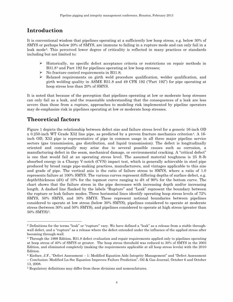
Introduction It is conventional wisdom that pipelines operating at a sufficiently low hoop stress, e.g. below 30% of SMYS or perhaps below 20% of SMYS, are immune to failing in a rupture mode and can only fail in a leak mode2
. This perceived lower degree of criticality is reflected in many practices or standards including but not limited to:
Historically, no specific defect acceptance criteria or restrictions on repair methods in B31.83
No fracture control requirements in B31.8; and Part 192 for pipelines operating at low hoop stresses;
Relaxed requirements on girth weld procedure qualification, welder qualification, and girth welding quality in ASME B31.8 and 49 CFR 192 (“Part 192”) for pipe operating at hoop stress less than 20% of SMYS.
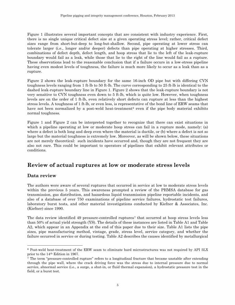
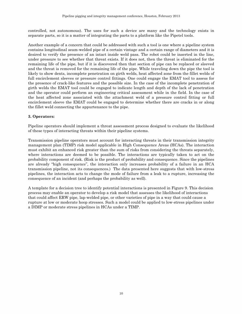
It is noted that because of the perception that pipelines operating at low or moderate hoop stresses can only fail as a leak, and the reasonable understanding that the consequences of a leak are less severe than those from a rupture, approaches to modeling risk implemented by pipeline operators may de-emphasize risk in pipelines operating at low or moderate hoop stresses. Theoretical factors Figure 1 depicts the relationship between defect size and failure stress level for a generic 16-inch OD x 0.250-inch WT Grade X52 line pipe, as predicted by a proven fracture mechanics criterion4. A 16-inch OD, X52 pipe is representative of pipe in common usage in all three major pipeline service sectors (gas transmission, gas distribution, and liquid transmission). The defect is longitudinally oriented and conceptually may arise due to several possible causes such as corrosion, a manufacturing defect in the seam, mechanical damage, or environmental cracking. A “critical defect” is one that would fail at an operating stress level. The assumed material toughness is 25 ft-lb absorbed energy in a Charpy V-notch (CVN) impact test, which is generally achievable in steel pipe produced by broad range pipe-making practices, manufacturers, and vintages applicable to this size and grade of pipe. The vertical axis is the ratio of failure stress to SMYS, where a ratio of 1.0 represents failure at 100% SMYS. The various curves represent differing depths of surface defect, e.g. depth/thickness (d/t) of 10% for the topmost curve ranging to d/t of 90% for the bottom curve. The chart shows that the failure stress in the pipe decreases with increasing depth and/or increasing length. A dashed line flanked by the labels “Rupture” and “Leak” represent the boundary between the rupture or leak failure modes. Three horizontal lines identify operating hoop stress levels of 72% SMYS, 50% SMYS, and 30% SMYS. These represent notional boundaries between pipelines considered to operate at low stress (below 30% SMYS), pipelines considered to operate at moderate stress (between 30% and 50% SMYS), and pipelines considered to operate at high stress (greater than 50% SMYS)5
2 Definitions for the terms “leak” or “rupture” vary. We have defined a “leak” as a release from a stable through-wall defect, and a “rupture” as a release where the defect extended under the influence of the applied stress after becoming through-wall.
.
3 Through the 1999 Edition, B31.8 defect evaluation and repair requirements applied only to pipelines operating at hoop stress of 40% of SMYS or greater. The hoop stress threshold was reduced to 30% of SMYS in the 2003 Edition, and eliminated completely (making the requirements applicable at all hoop stress levels) with the 2010 Edition. 4 Kiefner, J.F., “Defect Assessment – 1: Modified Equation Aids Integrity Management” and “Defect Assessment – Conclusion: Modified Ln-Sec Equation Improves Failure Prediction”, Oil & Gas Journal, October 6 and October 13, 2008. 5 Regulatory definitions may differ from these divisions and nomenclatures.
Pipeline pigging and integrity management conference, Houston, February 2013
5
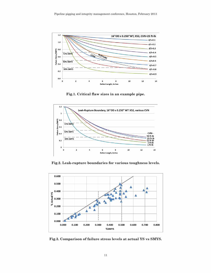
Figure 1 illustrates several important concepts that are consistent with industry experience. First, there is no single unique critical defect size at a given operating stress level; rather, critical defect sizes range from short-but-deep to long-but-shallow. Second, pipe operating at lower stress can tolerate larger (i.e., longer and/or deeper) defects than pipe operating at higher stresses. Third, combinations of defect depth, defect length, and hoop stress that lie to the left of the leak-rupture boundary would fail as a leak, while those that lie to the right of the line would fail as a rupture. These observations lead to the reasonable conclusion that if a failure occurs in a low-stress pipeline having even modest levels of toughness, the failure is much more likely to occur as a leak than as a rupture. Figure 2 shows the leak-rupture boundary for the same 16-inch OD pipe but with differing CVN toughness levels ranging from 1 ft-lb to 50 ft-lb. The curve corresponding to 25 ft-lb is identical to the dashed leak-rupture boundary line in Figure 1. Figure 2 shows that the leak-rupture boundary is not very sensitive to CVN toughness even down to 5 ft-lb, which is quite low. However, when toughness levels are on the order of 1 ft-lb, even relatively short defects can rupture at less than the highest stress levels. A toughness of 1 ft-lb, or even less, is representative of the bond line of ERW seams that have not been normalized by a post-weld heat-treatment6
even if the pipe body material exhibits normal toughness.
Figure 1 and Figure 2 can be interpreted together to recognize that there can exist situations in which a pipeline operating at low or moderate hoop stress can fail in a rupture mode, namely: (a) where a defect is both long and deep even where the material is ductile, or (b) where a defect is not so large but the material toughness is extremely low. Moreover, as will be shown below, these situations are not merely theoretical: such incidents have occurred and, though they are not frequent they are also not rare. This could be important to operators of pipelines that exhibit relevant attributes or conditions. Review of actual ruptures at low or moderate stress levels Data review The authors were aware of several ruptures that occurred in service at low to moderate stress levels within the previous 5 years. This awareness prompted a review of the PHMSA database for gas transmission, gas distribution, and hazardous liquid transmission pipeline reportable incidents, and also of a database of over 750 examinations of pipeline service failures, hydrostatic test failures, laboratory burst tests, and other material investigations conducted by Kiefner & Associates, Inc. (Kiefner) since 1990. The data review identified 49 pressure-controlled ruptures7
6 Post-weld heat-treatment of the ERW seam to eliminate hard microstructures was not required by API 5LX prior to the 14th Edition in 1967.
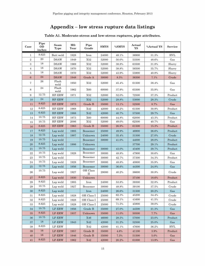
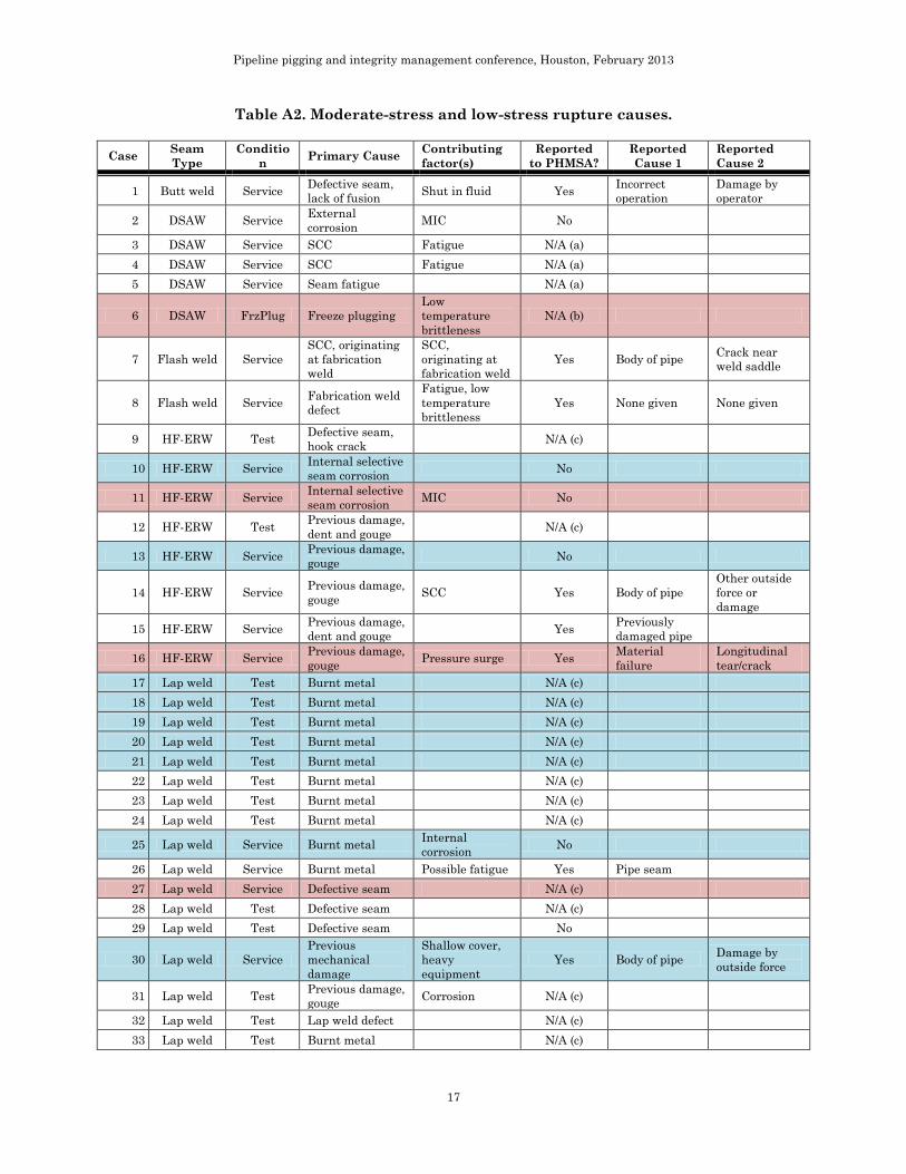
that occurred at hoop stress levels less than 50% of actual yield strength (YS). The details of these instances are listed in Table A1 and Table A2, which appear in an Appendix at the end of this paper due to their size. Table A1 lists the pipe sizes, pipe manufacturing method, vintage, grade, stress level, service category, and whether the failure occurred in service or during testing. Table A2 describes the causes identified by metallurgical
7 The term “pressure-controlled rupture” refers to a longitudinal fracture that became unstable after extending through the pipe wall, where the crack driving force was the stress due to internal pressure due to normal service, abnormal service (i.e., a surge, a shut-in, or fluid thermal expansion), a hydrostatic pressure test in the field, or a burst test.
Pipeline pigging and integrity management conference, Houston, February 2013
6
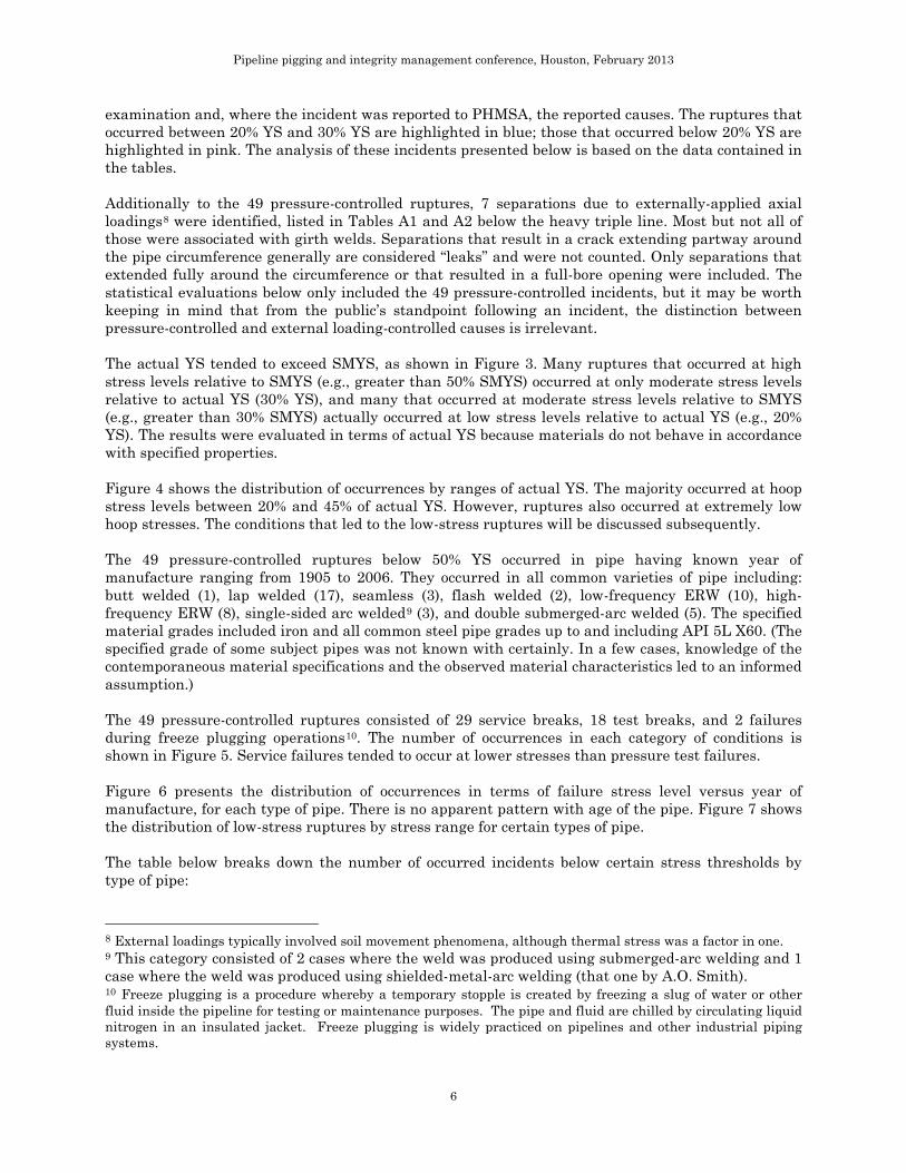
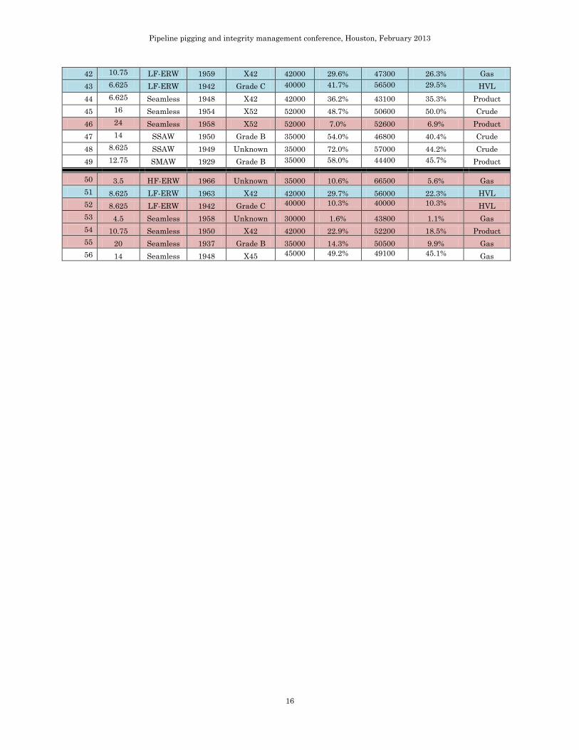
examination and, where the incident was reported to PHMSA, the reported causes. The ruptures that occurred between 20% YS and 30% YS are highlighted in blue; those that occurred below 20% YS are highlighted in pink. The analysis of these incidents presented below is based on the data contained in the tables. Additionally to the 49 pressure-controlled ruptures, 7 separations due to externally-applied axial loadings8
were identified, listed in Tables A1 and A2 below the heavy triple line. Most but not all of those were associated with girth welds. Separations that result in a crack extending partway around the pipe circumference generally are considered “leaks” and were not counted. Only separations that extended fully around the circumference or that resulted in a full-bore opening were included. The statistical evaluations below only included the 49 pressure-controlled incidents, but it may be worth keeping in mind that from the public’s standpoint following an incident, the distinction between pressure-controlled and external loading-controlled causes is irrelevant.
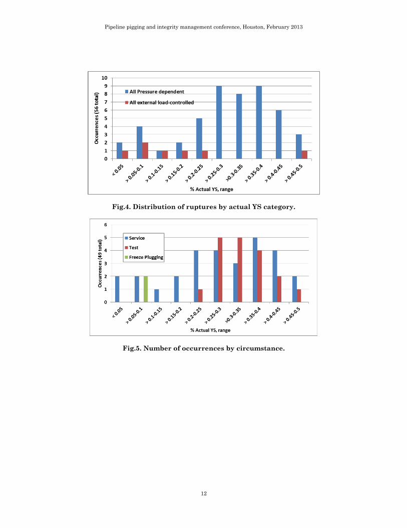
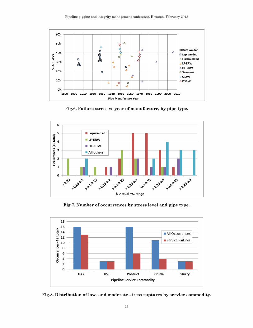
The actual YS tended to exceed SMYS, as shown in Figure 3. Many ruptures that occurred at high stress levels relative to SMYS (e.g., greater than 50% SMYS) occurred at only moderate stress levels relative to actual YS (30% YS), and many that occurred at moderate stress levels relative to SMYS (e.g., greater than 30% SMYS) actually occurred at low stress levels relative to actual YS (e.g., 20% YS). The results were evaluated in terms of actual YS because materials do not behave in accordance with specified properties. Figure 4 shows the distribution of occurrences by ranges of actual YS. The majority occurred at hoop stress levels between 20% and 45% of actual YS. However, ruptures also occurred at extremely low hoop stresses. The conditions that led to the low-stress ruptures will be discussed subsequently. The 49 pressure-controlled ruptures below 50% YS occurred in pipe having known year of manufacture ranging from 1905 to 2006. They occurred in all common varieties of pipe including: butt welded (1), lap welded (17), seamless (3), flash welded (2), low-frequency ERW (10), high-frequency ERW (8), single-sided arc welded9
(3), and double submerged-arc welded (5). The specified material grades included iron and all common steel pipe grades up to and including API 5L X60. (The specified grade of some subject pipes was not known with certainly. In a few cases, knowledge of the contemporaneous material specifications and the observed material characteristics led to an informed assumption.)
The 49 pressure-controlled ruptures consisted of 29 service breaks, 18 test breaks, and 2 failures during freeze plugging operations10
. The number of occurrences in each category of conditions is shown in Figure 5. Service failures tended to occur at lower stresses than pressure test failures.
Figure 6 presents the distribution of occurrences in terms of failure stress level versus year of manufacture, for each type of pipe. There is no apparent pattern with age of the pipe. Figure 7 shows the distribution of low-stress ruptures by stress range for certain types of pipe. The table below breaks down the number of occurred incidents below certain stress thresholds by type of pipe:
8 External loadings typically involved soil movement phenomena, although thermal stress was a factor in one. 9 This category consisted of 2 cases where the weld was produced using submerged-arc welding and 1 case where the weld was produced using shielded-metal-arc welding (that one by A.O. Smith). 10 Freeze plugging is a procedure whereby a temporary stopple is created by freezing a slug of water or other fluid inside the pipeline for testing or maintenance purposes. The pipe and fluid are chilled by circulating liquid nitrogen in an insulated jacket. Freeze plugging is widely practiced on pipelines and other industrial piping systems.
Pipeline pigging and integrity management conference, Houston, February 2013
7
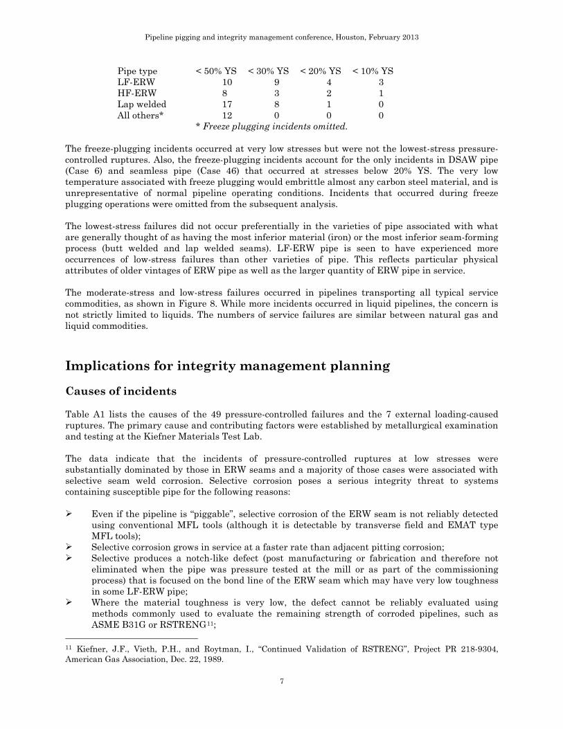
Pipe type < 50% YS < 30% YS < 20% YS < 10% YS LF-ERW 10 9 4 3 HF-ERW 8 3 2 1 Lap welded 17 8 1 0 All others* 12 0 0 0
* Freeze plugging incidents omitted. The freeze-plugging incidents occurred at very low stresses but were not the lowest-stress pressure-controlled ruptures. Also, the freeze-plugging incidents account for the only incidents in DSAW pipe (Case 6) and seamless pipe (Case 46) that occurred at stresses below 20% YS. The very low temperature associated with freeze plugging would embrittle almost any carbon steel material, and is unrepresentative of normal pipeline operating conditions. Incidents that occurred during freeze plugging operations were omitted from the subsequent analysis. The lowest-stress failures did not occur preferentially in the varieties of pipe associated with what are generally thought of as having the most inferior material (iron) or the most inferior seam-forming process (butt welded and lap welded seams). LF-ERW pipe is seen to have experienced more occurrences of low-stress failures than other varieties of pipe. This reflects particular physical attributes of older vintages of ERW pipe as well as the larger quantity of ERW pipe in service. The moderate-stress and low-stress failures occurred in pipelines transporting all typical service commodities, as shown in Figure 8. While more incidents occurred in liquid pipelines, the concern is not strictly limited to liquids. The numbers of service failures are similar between natural gas and liquid commodities. Implications for integrity management planning Causes of incidents Table A1 lists the causes of the 49 pressure-controlled failures and the 7 external loading-caused ruptures. The primary cause and contributing factors were established by metallurgical examination and testing at the Kiefner Materials Test Lab. The data indicate that the incidents of pressure-controlled ruptures at low stresses were substantially dominated by those in ERW seams and a majority of those cases were associated with selective seam weld corrosion. Selective corrosion poses a serious integrity threat to systems containing susceptible pipe for the following reasons:
Even if the pipeline is “piggable”, selective corrosion of the ERW seam is not reliably detected
using conventional MFL tools (although it is detectable by transverse field and EMAT type MFL tools);
Selective corrosion grows in service at a faster rate than adjacent pitting corrosion; Selective produces a notch-like defect (post manufacturing or fabrication and therefore not
eliminated when the pipe was pressure tested at the mill or as part of the commissioning process) that is focused on the bond line of the ERW seam which may have very low toughness in some LF-ERW pipe;
Where the material toughness is very low, the defect cannot be reliably evaluated using methods commonly used to evaluate the remaining strength of corroded pipelines, such as ASME B31G or RSTRENG11
11 Kiefner, J.F., Vieth, P.H., and Roytman, I., “Continued Validation of RSTRENG”, Project PR 218-9304, American Gas Association, Dec. 22, 1989.
;
Pipeline pigging and integrity management conference, Houston, February 2013
8
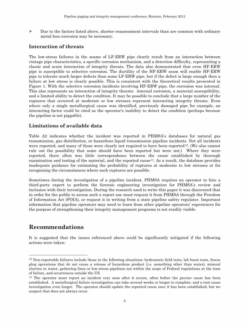
Due to the factors listed above, shorter reassessment intervals than are common with ordinary metal-loss corrosion may be necessary.
Interaction of threats The low-stress failures in the seams of LF-ERW pipe clearly result from an interaction between vintage pipe characteristics, a specific corrosion mechanism, and a detection difficulty, representing a classic and acute interaction of integrity threats. The data also demonstrated that even HF-ERW pipe is susceptible to selective corrosion. The ductility of the HF-ERW seam will enable HF-ERW pipe to tolerate much larger defects than some LF-ERW pipe, but if the defect is large enough then a failure at low stress is clearly possible. This is consistent with the theoretical results presented in Figure 1. With the selective corrosion incidents involving HF-ERW pipe, the corrosion was internal. This also represents an interaction of integrity threats: internal corrosion, a material susceptibility, and a limited ability to detect the condition. It may be possible to conclude that a large number of the ruptures that occurred at moderate or low stresses represent interacting integrity threats. Even where only a single metallurgical cause was identified, previously damaged pipe for example, an interacting factor could be cited as the operator’s inability to detect the condition (perhaps because the pipeline is not piggable). Limitations of available data Table A2 indicates whether the incident was reported in PHMSA’s databases for natural gas transmission, gas distribution, or hazardous liquid transmission pipeline incidents. Not all incidents were reported, and many of those were clearly not required to have been reported12. (We also cannot rule out the possibility that some should have been reported but were not.) Where they were reported, there often was little correspondence between the cause established by thorough examination and testing of the material, and the reported cause13
. As a result, the database provides inadequate guidance for estimating the probability of ruptures at moderate to low stresses or for recognizing the circumstances where such ruptures are possible.
Sometimes during the investigation of a pipeline incident, PHMSA requires an operator to hire a third-party expert to perform the forensic engineering investigation for PHMSA’s review and inclusion with their investigation. During the research used to write this paper it was discovered that in order for the public to access such a report one must request it from PHMSA through the Freedom of Information Act (FOIA), or request it in writing from a state pipeline safety regulator. Important information that pipeline operators may need to learn from other pipeline operators’ experiences for the purpose of strengthening their integrity management programs is not readily visible. Recommendations It is suggested that the issues referenced above could be significantly mitigated if the following actions were taken: 12 Non-reportable failures include those in the following situations: hydrostatic field tests, lab burst tests, freeze plug operations that do not cause a release of hazardous product (i.e. something other than water), mineral slurries in water, gathering lines or low-stress pipelines not within the scope of Federal regulations at the time of failure, and occurrences outside the US. 13 The operator must report an incident very soon after it occurs, often before the precise cause has been established. A metallurgical failure investigation can take several weeks or longer to complete, and a root cause investigation even longer. The operator should update the reported cause once it has been established, but we suspect that does not always occur.

Pipeline pigging and integrity management conference, Houston, February 2013
9
1. PHMSA: Incidents requiring third party forensics engineering reports by PHMSA should be “closed out” in a different way than they currently are, and the incident database needs improved quality control. Information from the forensic reports prepared by Kiefner enabled the authors to compare the conclusion regarding cause of the incident from these reports compared to the information regarding the same incidents in the PHMSA’s incident database. As mentioned above, in some cases the information either was not represented or the causes were not accurately represented. Pipeline operators would have to make a FOIA request to PHMSA or their state regulator to obtain similar information, in many instances. There are hundreds if not thousands of incident-related documents filed on a regular basis. We recognize that PHMSA has begun efforts to improve the quality control process for the data they receive from operators, and we commend them for this leadership. However, it will take some time to get the solutions in place. We note that PHMSA plans to hire new inspectors. As an interim solution we recommend that PHMSA consider utilizing some of the new resources to review and compare those required third party forensic engineering reports to the information filed by the operator to ensure that the conclusions from those reports are accurately represented in the incident database. This effort would improve the likelihood that incident information could be used to identify paradigm-breaking trend information such as the one discussed in this paper. 2. In-line tool manufacturers and service providers: In-line inspection tools having improved capability to be used as general inspection tools as well as “surgical” investigation devices are needed. There aren’t many in-line inspection (ILI) tools available for inspecting lower-stress lines especially those that operate at a hoop stress below 20% SMYS. The pressure often is insufficient to propel the vehicle at a steady speed, and such lines were often constructed with physical features that obstruct or interfere with the tools. There are self-propelled ILI devices such as those developed through NYSEARCH and the operators that have funded their research. These types of tools are effective and work using MFL and Eddy currents but may benefit from being able to use EMAT. The advantages they offer over traditional free swimming pigs are: a) They are not propelled by the product stream and therefore are independent of throughput,
which also controls speed excursions that could degrade data; b) They can adjust in place to fit around mitered bends and squeeze though plug valves. Rather
than spending 3 years to modify 5% of an operator’s pipeline before 95% of the line can be pigged, the operator can pig the 95% and then cut out the plug valves and other obstructions. This way the operator attains critical risk related information about the operations of their pipeline sooner than with a free swimming pig.
c) They have cameras on board which (at least in the case of natural gas in the line) can provide visual information along with the pig data which can improve an analyst’s interpretation of the data the pig provides.
Relative to the specific problem of the interaction of LF-ERW pipe and selective seam weld corrosion, self-propelled pigs such as the Pipetel Explorer combined with an EMAT tool could be the solution to finding the threat in the system. Most importantly though, the combination of video information, the ability to remotely pilot the device, and the ability to engage an EMAT tool on command means one could perform real time direct examination of a line from the inside of the pipe while gas is flowing. For the lack of a better description this could be considered an in-line robot (although they are remote
Pipeline pigging and integrity management conference, Houston, February 2013
10
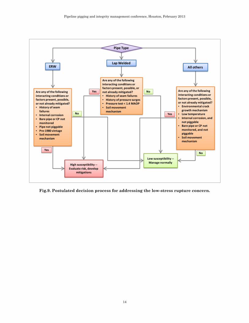
controlled, not autonomous). The uses for such a device are many and the technology exists in separate parts, so it is a matter of integrating the parts to a platform like the Pipetel tools. Another example of a concern that could be addressed with such a tool is one where a pipeline system contains longitudinal seam-welded pipe of a certain vintage and a certain range of diameters and it is desired to verify the presence of an intact inside weld pass. The robot could be inserted in the line, under pressure to see whether that threat exists. If it does not, then the threat is eliminated for the remaining life of the pipe, but if it is discovered then that section of pipe can be replaced or sleeved and the threat is removed for the remaining life of the pipe. While traveling down the pipe the tool is likely to show dents, incomplete penetration on girth welds, heat affected zone from the fillet welds of full encirclement sleeves or pressure control fittings. One could engage the EMAT tool to assess for the presence of crack-like features and the possible size. In the case of the incomplete penetration of girth welds the EMAT tool could be engaged to indicate length and depth of the lack of penetration and the operator could perform an engineering critical assessment while in the field. In the case of the heat affected zone associated with the attachment weld of a pressure control fitting or full encirclement sleeve the EMAT could be engaged to determine whether there are cracks in or along the fillet weld connecting the appurtenance to the pipe. 3. Operators: Pipeline operators should implement a threat assessment process designed to evaluate the likelihood of these types of interacting threats within their pipeline systems. Transmission pipeline operators must account for interacting threats in their transmission integrity management plan (TIMP) risk model applicable in High Consequence Areas (HCAs). The interaction must exhibit an enhanced risk greater than the sum of risks from considering the threats separately, where interactions are deemed to be possible. The interactions are typically taken to act on the probability component of risk. (Risk is the product of probability and consequence. Since the pipelines are already “high consequence”, the interaction only increases probability of a failure in an HCA transmission pipeline, not its consequences.) The data presented here suggests that with low-stress pipelines, the interaction acts to change the mode of failure from a leak to a rupture, increasing the consequence of an incident (and perhaps the probability as well). A template for a decision tree to identify potential interactions is presented in Figure 9. This decision process may enable an operator to develop a risk model that assesses the likelihood of interactions that could affect ERW pipe, lap-welded pipe, or other varieties of pipe in a way that could cause a rupture at low or moderate hoop stresses. Such a model could be applied to low-stress pipelines under a DIMP or moderate stress pipelines in HCAs under a TIMP.
Pipeline pigging and integrity management conference, Houston, February 2013
11
Fig.1. Critical flaw sizes in an example pipe.
Fig.2. Leak-rupture boundaries for various toughness levels.
Fig.3. Comparison of failure stress levels at actual YS vs SMYS.
Pipeline pigging and integrity management conference, Houston, February 2013
12
Fig.4. Distribution of ruptures by actual YS category.
Fig.5. Number of occurrences by circumstance.
Pipeline pigging and integrity management conference, Houston, February 2013
13
Fig.6. Failure stress vs year of manufacture, by pipe type.
Fig.7. Number of occurrences by stress level and pipe type.
Fig.8. Distribution of low- and moderate-stress ruptures by service commodity.
Pipeline pigging and integrity management conference, Houston, February 2013
14
Fig.9. Postulated decision process for addressing the low-stress rupture concern.
Pipe Type
ERWLap Welded
All others
Are any of the following interacting conditions or factors present, possible, or not already mitigated?• Environmental crack
growth mechanism• Low temperature• Internal corrosion, and
not piggable• Bare pipe or CP not
monitored, and not piggable
• Soil movement mechanism
Low susceptibility --Manage normally
Are any of the following interacting conditions or factors present, possible, or not already mitigated?• History of seam failures• History of pressure surges• Pressure test < 1.4 MAOP• Soil movement
mechanism
Are any of the following interacting conditions or factors present, possible, or not already mitigated?• History of seam
failures• Internal corrosion• Bare pipe or CP not
monitored• Pipe not piggable• Pre-1980 vintage• Soil movement
mechanism
High susceptibility --Evaluate risk, develop
mitigations
No
No
No
Yes
Yes
Yes
Pipeline pigging and integrity management conference, Houston, February 2013
15
Appendix – low stress rupture data listings
Table A1. Moderate-stress and low-stress ruptures, pipe attributes.
Case Pipe OD
inches Seam Type
Mfr Year
Pipe Grade SMYS %SMYS Actual
YS %Actual YS Service
1 8.625 Butt weld 1928 Iron 24000 48.1% 36900 31.3% HVL 2 20 DSAW 1949 X52 52000 50.0% 53500 48.6% Gas 3 18 DSAW 1969 X52 52000 38.8% 63500 31.8% Slurry 4 18 DSAW 1970 X52 52000 38.8% 56500 35.7% Slurry 5 18 DSAW 1970 X52 52000 43.9% 55900 40.8% Slurry 6 24 DSAW 1948 Grade A 30000 8.5% 36300 7.1% Crude
7 26 Flash weld 1950 X52 52000 45.4% 61500 38.4% Gas
8 24 Flash weld 1962 X60 60000 37.9% 63300 35.9% Gas
9 12.75 HF-ERW 1971 X52 52000 52.0% 72500 37.3% Product 10 24 HF-ERW X52 52000 28.8% 53000 28.3% Crude 11 8.625 HF-ERW 1973 Grade B 35000 13.1% 52500 8.7% Gas 12 8.625 HF-ERW 1968 X42 42000 45.2% 61500 30.9% Product 13 6.625 HF-ERW 1988 X42 42000 40.7% 57500 29.7% Gas 14 10.75 HF-ERW 1973 X60 60000 44.8% 62000 43.3% Product 15 10.75 HF-ERW 2006 X52 52000 49.0% 62500 40.7% Gas
16 8.625 HF-ERW 1963 Grade B 35000 26.9% 61500 15.3% Product
17 8.625 Lap weld 1905 Bessemer 25000 49.9% 46900 26.6% Product 18 12.75 Lap weld 1907 Unknown 24000 35.4% 31500 27.0% Crude 19 10.75 Lap weld Bessemer 30000 41.0% 44000 28.0% Product 20 8.625 Lap weld 1906 Unknown 37700 29.1% Product 21 10.75 Lap weld Bessemer 30000 43.0% 43400 29.7% Product 22 10.75 Lap weld 1928 Bessemer 30000 48.8% 47900 30.6% Gas 23 10.75 Lap weld
Bessemer 30000 42.7% 37300 34.3% Product 24 10.75 Lap weld 1928 Bessemer 30000 48.8% 40800 35.9% Gas 25 12.75 Lap weld 1956 Bessemer 30000 36.6% 44300 24.8% Gas
26 10.75 Lap weld 1927 OH Class II 28000 40.2% 36600 30.8% Crude
27 8.625 Lap weld 1930 Unknown 37100 18.6% Product 28 8.625 Lap weld 1905 Iron 24000 53.8% 39300 32.8% Product 29 10.75 Lap weld 1927 Bessemer 30000 48.8% 39100 37.5% Crude 30 8.625 Lap weld Iron 24000 26.6% 31500 20.2% Gas 31 8.625 Lap weld 1928 OH Class I 25000 62.3% 45200 34.4% Crude 32 8.625 Lap weld 1928 OH Class I 25000 69.1% 41600 41.5% Crude 33 8.625 Lap weld 1928 OH Class I 25000 71.5% 45900 39.0% Crude 34 10.75 LF-ERW 1956 Grade B 35000 27.0% 44500 21.3% Gas 35 8.625 LF-ERW 1937 Unknown 35000 11.0% 50500 7.7% Gas 36 10.75 LF-ERW X46 46000 28.5% 57000 23.0% Product 37 18 LF-ERW 1943 X42 42000 31.2% 52500 25.0% Gas 38 8.625 LF-ERW X42 42000 41.1% 47600 36.2% HVL 39 16 LF-ERW 1957 Grade B 35000 4.6% 41100 3.9% Product 40 16 LF-ERW 1946 Grade B 35000 7.3% 51500 5.0% Gas 41 8.625 LF-ERW 1962 X42 42000 20.2% 61000 13.9% Gas
Pipeline pigging and integrity management conference, Houston, February 2013
16
42 10.75 LF-ERW 1959 X42 42000 29.6% 47300 26.3% Gas 43 6.625 LF-ERW 1942 Grade C 40000 41.7% 56500 29.5% HVL 44 6.625 Seamless 1948 X42 42000 36.2% 43100 35.3% Product 45 16 Seamless 1954 X52 52000 48.7% 50600 50.0% Crude 46 24 Seamless 1958 X52 52000 7.0% 52600 6.9% Product 47 14 SSAW 1950 Grade B 35000 54.0% 46800 40.4% Crude 48 8.625 SSAW 1949 Unknown 35000 72.0% 57000 44.2% Crude 49 12.75 SMAW 1929 Grade B 35000 58.0% 44400 45.7% Product
50 3.5 HF-ERW 1966 Unknown 35000 10.6% 66500 5.6% Gas 51 8.625 LF-ERW 1963 X42 42000 29.7% 56000 22.3% HVL 52 8.625 LF-ERW 1942 Grade C 40000 10.3% 40000 10.3% HVL 53 4.5 Seamless 1958 Unknown 30000 1.6% 43800 1.1% Gas 54 10.75 Seamless 1950 X42 42000 22.9% 52200 18.5% Product 55 20 Seamless 1937 Grade B 35000 14.3% 50500 9.9% Gas 56 14 Seamless 1948 X45 45000 49.2% 49100 45.1% Gas
Pipeline pigging and integrity management conference, Houston, February 2013
17
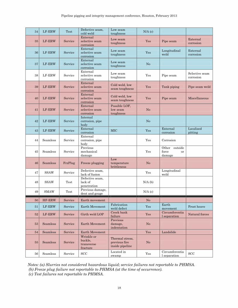
Table A2. Moderate-stress and low-stress rupture causes.
Case Seam Type
Condition Primary Cause Contributing
factor(s) Reported
to PHMSA? Reported Cause 1
Reported Cause 2
1 Butt weld Service Defective seam, lack of fusion Shut in fluid Yes Incorrect
operation Damage by operator
2 DSAW Service External corrosion MIC No
3 DSAW Service SCC Fatigue N/A (a) 4 DSAW Service SCC Fatigue N/A (a) 5 DSAW Service Seam fatigue N/A (a)
6 DSAW FrzPlug Freeze plugging Low temperature brittleness
N/A (b)
7 Flash weld Service SCC, originating at fabrication weld
SCC, originating at fabrication weld
Yes Body of pipe Crack near weld saddle
8 Flash weld Service Fabrication weld defect
Fatigue, low temperature brittleness
Yes None given None given
9 HF-ERW Test Defective seam, hook crack N/A (c)
10 HF-ERW Service Internal selective seam corrosion No
11 HF-ERW Service Internal selective seam corrosion MIC No
12 HF-ERW Test Previous damage, dent and gouge N/A (c)
13 HF-ERW Service Previous damage, gouge No
14 HF-ERW Service Previous damage, gouge SCC Yes Body of pipe
Other outside force or damage
15 HF-ERW Service Previous damage, dent and gouge Yes Previously
damaged pipe
16 HF-ERW Service Previous damage, gouge Pressure surge Yes Material
failure Longitudinal tear/crack
17 Lap weld Test Burnt metal N/A (c) 18 Lap weld Test Burnt metal N/A (c) 19 Lap weld Test Burnt metal N/A (c) 20 Lap weld Test Burnt metal N/A (c) 21 Lap weld Test Burnt metal N/A (c) 22 Lap weld Test Burnt metal N/A (c) 23 Lap weld Test Burnt metal N/A (c) 24 Lap weld Test Burnt metal N/A (c)
25 Lap weld Service Burnt metal Internal corrosion No
26 Lap weld Service Burnt metal Possible fatigue Yes Pipe seam 27 Lap weld Service Defective seam N/A (c) 28 Lap weld Test Defective seam N/A (c) 29 Lap weld Test Defective seam No
30 Lap weld Service Previous mechanical damage
Shallow cover, heavy equipment
Yes Body of pipe Damage by outside force
31 Lap weld Test Previous damage, gouge Corrosion N/A (c)
32 Lap weld Test Lap weld defect N/A (c) 33 Lap weld Test Burnt metal N/A (c)
Pipeline pigging and integrity management conference, Houston, February 2013
18
34 LF-ERW Test Defective seam, cold weld
Low seam toughness N/A (c)
35 LF-ERW Service External selective seam corrosion
Low seam toughness Yes Pipe seam External
corrosion
36 LF-ERW Service External selective seam corrosion
Low seam toughness Yes Longitudinal
weld External corrosion
37 LF-ERW Service External selective seam corrosion
Low seam toughness No
38 LF-ERW Service External selective seam corrosion
Low seam toughness Yes Pipe seam Selective seam
corrosion
39 LF-ERW Service External selective seam corrosion
Cold weld, low seam toughness Yes Tank piping Pipe seam weld
40 LF-ERW Service External selective seam corrosion
Cold weld, low seam toughness Yes Pipe seam Miscellaneous
41 LF-ERW Service External selective seam corrosion
Possible LOF, low seam toughness
No
42 LF-ERW Service Internal corrosion, pipe body
No
43 LF-ERW Service External corrosion MIC Yes External
corrosion Localized pitting
44 Seamless Service External corrosion, pipe body
Yes Corrosion
45 Seamless Service Previous mechanical damage
Yes Other outside force or damage
46 Seamless FrzPlug Freeze plugging Low temperature brittleness
No
47 SSAW Service Defective seam, lack of fusion Yes Longitudinal
weld
48 SSAW Test Defective seam, lack of penetration
N/A (b)
49 SMAW Test Previous damage, dent and gouge N/A (c)
50 HF-ERW Service Earth movement No
51 LF-ERW Service Earth Movement Fabrication weld defect Yes Earth
movement Frost heave
52 LF-ERW Service Girth weld LOP Creek bank failure Yes Circumferentia
l separation Natural forces
53 Seamless Service Earth Movement Previous damage, indentation
No
54 Seamless Service Earth Movement Yes Landslide
55 Seamless Service Wrinkle or buckle, transverse fracture
Thermal stress, previous fire inside pipeline
No
56 Seamless Service SCC Located in swamp Yes Circumferentia
l separation SCC
Notes: (a) Slurries not considered hazardous liquid; service failures not reportable to PHMSA. (b) Freeze plug failure not reportable to PHMSA (at the time of occurrence). (c) Test failures not reportable to PHMSA.