Study of oxygen evolution reaction on amorphous Au13 ...
12
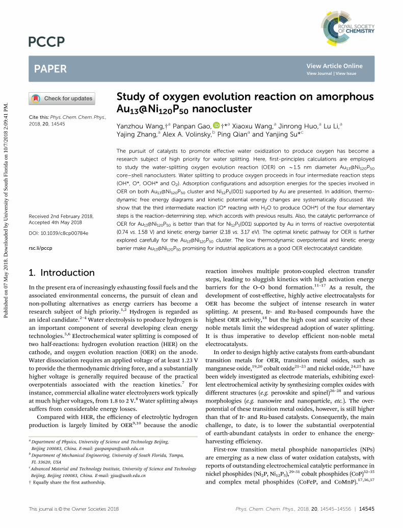
This journal is © the Owner Societies 2018 Phys. Chem. Chem. Phys., 2018, 20, 14545--14556 | 14545 Cite this: Phys. Chem. Chem. Phys., 2018, 20, 14545 Study of oxygen evolution reaction on amorphous Au 13 @Ni 120 P 50 nanocluster Yanzhou Wang,† a Panpan Gao, †* a Xiaoxu Wang, a Jinrong Huo, a Lu Li, a Yajing Zhang, a Alex A. Volinsky, b Ping Qian a and Yanjing Su* c The pursuit of catalysts to promote effective water oxidization to produce oxygen has become a research subject of high priority for water splitting. Here, first-principles calculations are employed to study the water-splitting oxygen evolution reaction (OER) on B1.5 nm diameter Au 13 @Ni 120 P 50 core–shell nanoclusters. Water splitting to produce oxygen proceeds in four intermediate reaction steps (OH*, O*, OOH* and O 2 ). Adsorption configurations and adsorption energies for the species involved in OER on both Au 13 @Ni 120 P 50 cluster and Ni 12 P 5 (001) supported by Au are presented. In addition, thermo- dynamic free energy diagrams and kinetic potential energy changes are systematically discussed. We show that the third intermediate reaction (O* reacting with H 2 O to produce OOH*) of the four elementary steps is the reaction-determining step, which accords with previous results. Also, the catalytic performance of OER for Au 13 @Ni 120 P 50 is better than that for Ni 12 P 5 (001) supported by Au in terms of reactive overpotential (0.74 vs. 1.58 V) and kinetic energy barrier (2.18 vs. 3.17 eV). The optimal kinetic pathway for OER is further explored carefully for the Au 13 @Ni 120 P 50 cluster. The low thermodynamic overpotential and kinetic energy barrier make Au 13 @Ni 120 P 50 promising for industrial applications as a good OER electrocatalyst candidate. 1. Introduction In the present era of increasingly exhausting fossil fuels and the associated environmental concerns, the pursuit of clean and non-polluting alternatives as energy carriers has become a research subject of high priority. 1,2 Hydrogen is regarded as an ideal candidate. 2–4 Water electrolysis to produce hydrogen is an important component of several developing clean energy technologies. 5,6 Electrochemical water splitting is composed of two half-reactions: hydrogen evolution reaction (HER) on the cathode, and oxygen evolution reaction (OER) on the anode. Water dissociation requires an applied voltage of at least 1.23 V to provide the thermodynamic driving force, and a substantially higher voltage is generally required because of the practical overpotentials associated with the reaction kinetics. 7 For instance, commercial alkaline water electrolyzers work typically at much higher voltages, from 1.8 to 2 V. 8 Water splitting always suffers from considerable energy losses. Compared with HER, the efficiency of electrolytic hydrogen production is largely limited by OER 9,10 because the anodic reaction involves multiple proton-coupled electron transfer steps, leading to sluggish kinetics with high activation energy barriers for the O–O bond formation. 11–17 As a result, the development of cost-effective, highly active electrocatalysts for OER has become the subject of intense research in water splitting. At present, Ir- and Ru-based compounds have the highest OER activity, 18 but the high cost and scarcity of these noble metals limit the widespread adoption of water splitting. It is thus imperative to develop efficient non-noble metal electrocatalysts. In order to design highly active catalysts from earth-abundant transition metals for OER, transition metal oxides, such as manganese oxide, 19,20 cobalt oxide 21–23 and nickel oxide, 24,25 have been widely investigated as electrode materials, exhibiting excel- lent electrochemical activity by synthesizing complex oxides with different structures (e.g. perovskite and spinel) 26–28 and various morphologies (e.g. nanowire and nanoparticle, etc.). The over- potential of these transition metal oxides, however, is still higher than that of Ir- and Ru-based catalysts. Consequently, the main challenge, to date, is to lower the substantial overpotential of earth-abundant catalysts in order to enhance the energy- harvesting efficiency. First-row transition metal phosphide nanoparticles (NPs) are emerging as a new class of water oxidation catalysts, with reports of outstanding electrochemical catalytic performance in nickel phosphides (Ni 2 P, Ni 12 P 5 ), 29–31 cobalt phosphides (CoP) 32–35 and complex metal phosphides (CoFeP, and CoMnP). 17,36,37 a Department of Physics, University of Science and Technology Beijing, Beijing 100083, China. E-mail: [email protected] b Department of Mechanical Engineering, University of South Florida, Tampa, FL 33620, USA c Advanced Material and Technology Institute, University of Science and Technology Beijing, Beijing 100083, China. E-mail: [email protected] † Equally share the first authorship. Received 2nd February 2018, Accepted 4th May 2018 DOI: 10.1039/c8cp00784e rsc.li/pccp PCCP PAPER Published on 07 May 2018. Downloaded by University of South Florida on 10/7/2018 2:09:41 PM. View Article Online View Journal | View Issue
Transcript of Study of oxygen evolution reaction on amorphous Au13 ...
This journal is© the Owner Societies 2018 Phys. Chem. Chem. Phys., 2018, 20, 14545--14556 | 14545
Cite this:Phys.Chem.Chem.Phys.,
2018, 20, 14545
Study of oxygen evolution reaction on amorphousAu13@Ni120P50 nanocluster
Yanzhou Wang,†a Panpan Gao, †*a Xiaoxu Wang,a Jinrong Huo,a Lu Li,a
Yajing Zhang,a Alex A. Volinsky,b Ping Qiana and Yanjing Su*c
The pursuit of catalysts to promote effective water oxidization to produce oxygen has become a
research subject of high priority for water splitting. Here, first-principles calculations are employed
to study the water-splitting oxygen evolution reaction (OER) on B1.5 nm diameter Au13@Ni120P50
core–shell nanoclusters. Water splitting to produce oxygen proceeds in four intermediate reaction steps
(OH*, O*, OOH* and O2). Adsorption configurations and adsorption energies for the species involved in
OER on both Au13@Ni120P50 cluster and Ni12P5(001) supported by Au are presented. In addition, thermo-
dynamic free energy diagrams and kinetic potential energy changes are systematically discussed. We
show that the third intermediate reaction (O* reacting with H2O to produce OOH*) of the four elementary
steps is the reaction-determining step, which accords with previous results. Also, the catalytic performance of
OER for Au13@Ni120P50 is better than that for Ni12P5(001) supported by Au in terms of reactive overpotential
(0.74 vs. 1.58 V) and kinetic energy barrier (2.18 vs. 3.17 eV). The optimal kinetic pathway for OER is further
explored carefully for the Au13@Ni120P50 cluster. The low thermodynamic overpotential and kinetic energy
barrier make Au13@Ni120P50 promising for industrial applications as a good OER electrocatalyst candidate.
1. Introduction
In the present era of increasingly exhausting fossil fuels and theassociated environmental concerns, the pursuit of clean andnon-polluting alternatives as energy carriers has become aresearch subject of high priority.1,2 Hydrogen is regarded asan ideal candidate.2–4 Water electrolysis to produce hydrogen isan important component of several developing clean energytechnologies.5,6 Electrochemical water splitting is composed oftwo half-reactions: hydrogen evolution reaction (HER) on thecathode, and oxygen evolution reaction (OER) on the anode.Water dissociation requires an applied voltage of at least 1.23 Vto provide the thermodynamic driving force, and a substantiallyhigher voltage is generally required because of the practicaloverpotentials associated with the reaction kinetics.7 Forinstance, commercial alkaline water electrolyzers work typicallyat much higher voltages, from 1.8 to 2 V.8 Water splitting alwayssuffers from considerable energy losses.
Compared with HER, the efficiency of electrolytic hydrogenproduction is largely limited by OER9,10 because the anodic
reaction involves multiple proton-coupled electron transfersteps, leading to sluggish kinetics with high activation energybarriers for the O–O bond formation.11–17 As a result, thedevelopment of cost-effective, highly active electrocatalysts forOER has become the subject of intense research in watersplitting. At present, Ir- and Ru-based compounds have thehighest OER activity,18 but the high cost and scarcity of thesenoble metals limit the widespread adoption of water splitting.It is thus imperative to develop efficient non-noble metalelectrocatalysts.
In order to design highly active catalysts from earth-abundanttransition metals for OER, transition metal oxides, such asmanganese oxide,19,20 cobalt oxide21–23 and nickel oxide,24,25 havebeen widely investigated as electrode materials, exhibiting excel-lent electrochemical activity by synthesizing complex oxides withdifferent structures (e.g. perovskite and spinel)26–28 and variousmorphologies (e.g. nanowire and nanoparticle, etc.). The over-potential of these transition metal oxides, however, is still higherthan that of Ir- and Ru-based catalysts. Consequently, the mainchallenge, to date, is to lower the substantial overpotentialof earth-abundant catalysts in order to enhance the energy-harvesting efficiency.
First-row transition metal phosphide nanoparticles (NPs)are emerging as a new class of water oxidation catalysts, withreports of outstanding electrochemical catalytic performance innickel phosphides (Ni2P, Ni12P5),29–31 cobalt phosphides (CoP)32–35
and complex metal phosphides (CoFeP, and CoMnP).17,36,37
a Department of Physics, University of Science and Technology Beijing,
Beijing 100083, China. E-mail: [email protected] Department of Mechanical Engineering, University of South Florida, Tampa,
FL 33620, USAc Advanced Material and Technology Institute, University of Science and Technology
Beijing, Beijing 100083, China. E-mail: [email protected]
† Equally share the first authorship.
Received 2nd February 2018,Accepted 4th May 2018
DOI: 10.1039/c8cp00784e
rsc.li/pccp
PCCP
PAPER
Publ
ishe
d on
07
May
201
8. D
ownl
oade
d by
Uni
vers
ity o
f So
uth
Flor
ida
on 1
0/7/
2018
2:0
9:41
PM
.
View Article OnlineView Journal | View Issue

14546 | Phys. Chem. Chem. Phys., 2018, 20, 14545--14556 This journal is© the Owner Societies 2018
Nickel phosphides, especially, have been shown to possessnaturally promising high activity, not only in HER but also inOER. Moreover, the good physical properties of nickel phosphidesare also desirable for electrochemical catalytic electrodes. It isreported that nickel-rich phosphides are not only good conductorsof both heat and electricity; their hardness and strength are alsocomparable to some ceramics.38
Increasing specific surface area is a favorable way to improvethe efficiency of water splitting, and many efforts have beendevoted to synthesizing a wide variety of nanostructures, suchas NPs, nanowires, nanorods, nanotubes, and nanoplatelets. Core–shell heterogeneous nanoparticles with tunable compositionand morphology exhibit multiple functionalities in catalysis.Compared with homogenous NPs, core–shell heterogeneousNPs have the following advantages. First, catalysts such ascore–shell NPs allow greater tunability in reactivity and moreflexibility in the nanostructure design. Second, core–shell bimetallicNPs could induce distinct strain effects to tailor catalytic reactivityand selectivity.
Density functional theory (DFT) investigations have beensuccessfully applied to reveal the precise catalytic mechanism,involving adsorption structures, decomposition modes, reactionpathways, reaction kinetics and thermodynamics. Recently,Au@Ni12P5 core–shell single-crystal NPs have been experimentallyshown to exhibit efficient OER catalytic ability and to be the mosteffective in water splitting among Au@Ni12P5 core–shell, Au–Ni12P5
oligomer-like and pure Ni12P5 NPs.29 However, to the best of ourknowledge, the detailed reaction of Au@Ni12P5 NPs in catalyzingwater to generate oxygen is not convincingly accounted forat the atomic level. Herein, we modeled and developed theAu13@Ni120P50 NP catalyst. Periodic DFT was performed toinvestigate the adsorption configurations, elementary reactionprocesses, potential energy surfaces and energy barrier analysisto illustrate the important role the Au13@Ni120P50 nanoclusterplays in OER at the anode, highlighting the crucial effect of thereaction intermediate (OOH*) on the catalytic activity. Ourresults indicate that oxygen formation undergoes a distinctlylower activation energy barrier with the Au13@Ni120P50 NPcatalyst than with the clean Ni12P5(001) facet.
2. Computational details and methods
All calculations in the present paper were performed by employingthe Vienna ab initio simulation package (VASP)39 based on thedensity functional theory (DFT) within the general gradientapproximation parameterized by Perdew, Burke and Ernzerhof(PBE).40 The electron–ion potential was described by the projectoraugmented wave (PAW) method41 with 3d4s, 3s3p, and 5d6s forNi, P and Au atoms, respectively. The plane wave expansion withkinetic cutoff of 450 eV [520 eV for the Ni12P5(001) slab] was usedafter careful convergence tests. The vacuum spaces for clusterswere not less than 12 Å to avoid any artificial interactions. Energyconvergence was reached when forces on the relaxed atoms wereless than 0.01 eV Å�1 in all calculations involving Au13@Ni120P50
and Ni12P5(001) supported by bulk Au, except for the transition
state locations less than 0.05 eV Å�1 because of the highcomputational cost. Only the gamma point was adopted tosample the Brillouin zone for the nanocluster and adsorbedmolecule, but the 3 � 3 � 1 Monkhorst–Pack grid was adoptedfor Ni12P5(001) supported by bulk Au. Smearing of 0.2 eV [0.1 eVfor Ni12P5(001)] for the orbital occupancy was applied to achieveaccurate electronic convergence in calculations involving theAu13@Ni120P50 nanocluster. The ion positions were allowed torelax in order to find the minimum energy configuration usingthe conjugate gradient algorithm.
Simulated annealing ab initio molecular dynamics (AIMD)runs were carried out to obtain the ground-state core–shellstructure. The Au13@Ni120P50 system was initialized at 0 K andheated to 300 K over 30 ps, then cooled back down to 0 K over90 ps. Temperature was controlled using the Nose–Hooverthermostat, and the ionic trajectories were propagated with atime step of 3 fs. Along the simulated annealing, snapshotswere selected as candidates after every 2000 time steps,which were then relaxed to the nearest local minimum usingthe conjugate gradient algorithm. Finally, the lowest energyconfiguration among them was selected as the most stablecore–shell structure.
For the molecule adsorption process, an empirical van derWaals (vdW) correction proposed by Grime (DFT+D3),42 whichplays an important role in weakly adsorbed systems,43,44 wasperformed to describe interactions between the cluster andthe adsorbates. Furthermore, the climbing image nudgedelastic band (CINEB) method,45 a tool in the VASP code, isan effective way to locate the minimum energy path from adesignated initial state to a designated final state for the OER.Thus, we presented an optimized overall reactive path with thesmallest potential barrier on the Au13@Ni120P50 core–shellstructure.
The adsorption energy (Eads), which measures the strengthof the interaction of the adsorbate with the cluster surface, iscalculated as:
Eads = Egas/cluster � Egas � Ecluster, (1)
where Egas/cluster is the total energy of an adsorbate at thecluster, Egas is the energy of the free gas-phase species andEcluster is the energy of the cluster. The reaction energy (DE) andenergy barrier (Ea) of each step in the cluster were calculatedaccording to the following formulas:
DE = EFS � EIS (2)
and
Ea = ETS � EIS, (3)
where, EIS, ETS and EFS are total energies of the initial state (IS),transition state (TS) and the final state (FS), respectively.
3. Results and discussion
For clarity, this section is arranged as follows. First, thestructure and thermal stability of the Au13@Ni120P50 nanocluster
Paper PCCP
Publ
ishe
d on
07
May
201
8. D
ownl
oade
d by
Uni
vers
ity o
f So
uth
Flor
ida
on 1
0/7/
2018
2:0
9:41
PM
. View Article Online

This journal is© the Owner Societies 2018 Phys. Chem. Chem. Phys., 2018, 20, 14545--14556 | 14547
are presented. Then, the adsorption configurations of involvedmolecules and intermediates are discussed. Moreover, free energydiagrams, potential energy surfaces, the energy barrier and theoptimal kinetic pathway are explored and analyzed.
To check the accuracy of our theoretical methods, basedon the DFT combined with the GGA exchange–correlationfunctional, we first predicted the lattice constant, cohesiveenergy and the bulk modulus of Ni12P5 and Au at the ground-state bulk structures, respectively. Our calculated results for theground-state structures are summarized in Table 1. Comparedwith the PBE, bulk properties of both Ni12P5 and Au basedon the PBE+D3 are generally in better agreement with experi-ments. This is because the PBE+D3 includes both two- andthree-dimensional body terms. Specifically, the PBE over-estimates the lattice constants, while the equilibrium latticeconstants with the PBE+D3 correction are smaller than the PBEresults. Furthermore, the cohesive energy and bulk moduluscomputed by the PBE are generally underestimated. The resultscomputed with the van der Waals correction (D3) are in betteragreement with experiments.
3.1 Structures of Au13@Ni120P50 and Ni12P5(001) supported bybulk Au
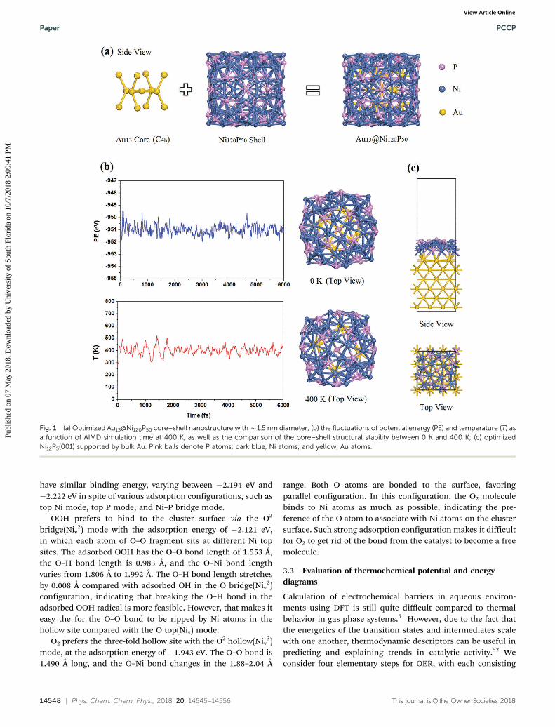
Considering the practical difficulty of exploring the lowestenergy configuration of the Au13@Ni120P50 core–shell due tothe complexity and multiple possibilities in combining theAu-core and the Ni12P5-shell cluster by the first-principlescalculations and simulations, AIMD was employed to performannealing-based searches for the ground-state structure inFig. 1. Gold cluster consisting of 13 atoms was selected as acore to contribute to the core shell structure with C4h due to thefirst magic number, according to the geometric model, to formvarious high symmetries. As seen in Fig. 1(a), the central atomin the Au13-core cluster binds to four nearest neighboringatoms with the bond length of 2.767 Å, and a plane is formedby the five atoms, exhibiting four-fold symmetry. Each atomnext to the central atom is bound to its nearest neighboring twoatoms with the bond length of 2.849 Å and an angle of about1201. Cage cylinder-like (Ni12P5)10-cluster was constructed as ashell based on bulk Ni12P5 to act as the initial configuration.Stable core–shell simulated annealing nanocluster with B1.5 nmdiameter tends to have amorphous structure, possibly attributed tomultiplicity and tough tunability of the core–shell heterostructureas well as the complexity of Ni12P5. Considering the temperatureenvironment in practical application, AIMD runs at 400 K were
carried out to investigate thermodynamic stability using theNose–Hoover thermostat in the canonical NVT ensemble.The trajectories were detected within the whole range of 6 pssimulation with step of 2 fs. The Fig. 1(b) presents the fluctuationsin temperature and potential energy as a function of the simulationtime. After 6 ps, structural destruction of the Au13@Ni120P50 core–shell phase did not occur, except for some thermal fluctuations. Thechanges of bond length are small with respect to the temperaturevariation. It is thus reasonable to infer the thermal stability of thecore–shell structure.
3.2 Adsorption configurations
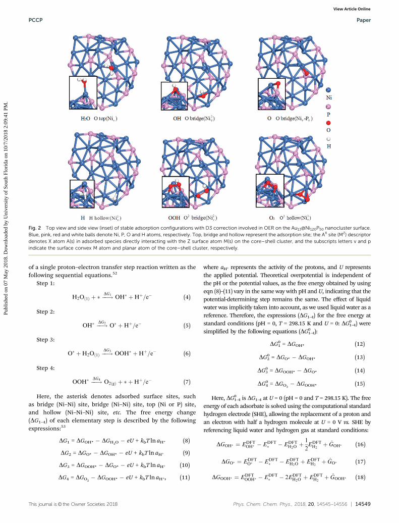
Stable and metastable structures of species involved in OER forthe Au13@Ni120P50 are presented in Fig. 2 and 3, respectively.For comparison, we also studied flat and clean surfaces ofNi12P5(001) due to its more stable facet compared to otherfacets.48 Adsorption energy and structural parameters of adsorptionconfigurations are listed in Table 2 for the nanocluster and inTable 3 for the Ni12P5(001) supported by bulk Au. As shown in Fig. 2,the most stable adsorption configuration of H2O was at the top siteof one convex Ni atom on the Au13@Ni120P50 NP surface, withthe O–Ni bond length obtained with D3 being 2.023 Å and theadsorption energy of �0.831 eV. The straight line made bythe oxygen atom of water molecule bonded to one nickel atomis almost perpendicular to the plane formed by the watermolecule, which is in accord with the evidence49 that O atombinds preferentially near the top site of the transition metalatoms, and the plane formed by the water molecule is nearlyparallel to the surface. For isolated gas-phase water molecule,optimized O–H bond length and HOH angle are 0.972 Å and104.51, respectively, in excellent agreement with experimental50
values (O–H bond lengths of 0.96 Å and HOH angle of 104.51)obtained by spectroscopic techniques. O–H bond length of0.975 Å and HOH angle of 106.61 were found for the watermolecule adsorbed on the cluster. This indicates that the molecularstructure of H2O is slightly perturbed upon adsorption, which iscrucial for the OER on the cluster.
The strongest adsorption among all possible modes foradsorbed OH is due to the oxygen atom in the OH radicallocated at the Ni–Ni bridge site, whose binding energy is�3.803 eV, with the O–Ni bond lengths of 1.907 Å and 1.943 Å,respectively. Compared with the free radical (0.988 Å), the bondlength of OH adsorbed on the cluster (0.975 Å) is reduced by0.013 Å, indicating that the new O–Ni bond has weakened theOH bond strength.
The most energetically favorable configuration among allpossible modes of atomic oxygen binding is the oxygen at theconvex Ni–P bridge site, with O–Ni binding length of 1.918 Åand O–P binding length of 1.577 Å. The corresponding optimizedbinding energy is �5.814 eV, which seems to indicate a strongerinteraction somewhat between atomic oxygen and atomic nickeland phosphorus, which is unfavorable for the subsequent atomicoxygen reaction with adjacent molecular water to produce OOH.
H atom shows the highest preference for the Ni three-foldhollow site, with an adsorption of �2.990 eV. The H–Ni bondlength ranges from 1.677 Å to 1.781 Å. The metastable structures
Table 1 Bulk properties, including lattice constants (a, c), cohesive energy(Eb) and bulk modulus (B) for both tetragonal Ni12P5 and cubic Au,calculated using PBE and PBE+D3, compared with experiments (Exp.)
Ni12P5 Au
PBE PBE+D3 Expt.46 PBE PBE+D3 Exp.47
a 8.634 8.55 8.645 4.172 4.117 4.079c (Å) 5.078 4.993 5.069 — — —Eb (eV per atom) 4.93 5.44 — 2.99 3.62 3.81B (GPa) 101.3 153.8 — 133.5 156.5 163–175
PCCP Paper
Publ
ishe
d on
07
May
201
8. D
ownl
oade
d by
Uni
vers
ity o
f So
uth
Flor
ida
on 1
0/7/
2018
2:0
9:41
PM
. View Article Online
14548 | Phys. Chem. Chem. Phys., 2018, 20, 14545--14556 This journal is© the Owner Societies 2018
have similar binding energy, varying between �2.194 eV and�2.222 eV in spite of various adsorption configurations, such astop Ni mode, top P mode, and Ni–P bridge mode.
OOH prefers to bind to the cluster surface via the O2
bridge(Niv2) mode with the adsorption energy of �2.121 eV,
in which each atom of O–O fragment sits at different Ni topsites. The adsorbed OOH has the O–O bond length of 1.553 Å,the O–H bond length is 0.983 Å, and the O–Ni bond lengthvaries from 1.806 Å to 1.992 Å. The O–H bond length stretchesby 0.008 Å compared with adsorbed OH in the O bridge(Niv
2)configuration, indicating that breaking the O–H bond in theadsorbed OOH radical is more feasible. However, that makes iteasy the for the O–O bond to be ripped by Ni atoms in thehollow site compared with the O top(Niv) mode.
O2 prefers the three-fold hollow site with the O2 hollow(Niv3)
mode, at the adsorption energy of �1.943 eV. The O–O bond is1.490 Å long, and the O–Ni bond changes in the 1.88–2.04 Å
range. Both O atoms are bonded to the surface, favoringparallel configuration. In this configuration, the O2 moleculebinds to Ni atoms as much as possible, indicating the pre-ference of the O atom to associate with Ni atoms on the clustersurface. Such strong adsorption configuration makes it difficultfor O2 to get rid of the bond from the catalyst to become a freemolecule.
3.3 Evaluation of thermochemical potential and energydiagrams
Calculation of electrochemical barriers in aqueous environ-ments using DFT is still quite difficult compared to thermalbehavior in gas phase systems.51 However, due to the fact thatthe energetics of the transition states and intermediates scalewith one another, thermodynamic descriptors can be useful inpredicting and explaining trends in catalytic activity.52 Weconsider four elementary steps for OER, with each consisting
Fig. 1 (a) Optimized Au13@Ni120P50 core–shell nanostructure with B1.5 nm diameter; (b) the fluctuations of potential energy (PE) and temperature (T) asa function of AIMD simulation time at 400 K, as well as the comparison of the core–shell structural stability between 0 K and 400 K; (c) optimizedNi12P5(001) supported by bulk Au. Pink balls denote P atoms; dark blue, Ni atoms; and yellow, Au atoms.
Paper PCCP
Publ
ishe
d on
07
May
201
8. D
ownl
oade
d by
Uni
vers
ity o
f So
uth
Flor
ida
on 1
0/7/
2018
2:0
9:41
PM
. View Article Online
This journal is© the Owner Societies 2018 Phys. Chem. Chem. Phys., 2018, 20, 14545--14556 | 14549
of a single proton–electron transfer step reaction written as thefollowing sequential equations.52
Step 1:
H2Oð1Þ þ � ��!DG1
OH� þHþ=e� (4)
Step 2:
OH� ��!DG2O� þHþ=e� (5)
Step 3:
O� þH2Oð1Þ ��!DG3
OOH� þHþ=e� (6)
Step 4:
OOH� ��!DG4O2ðgÞ þ � þHþ=e� (7)
Here, the asterisk denotes adsorbed surface sites, suchas bridge (Ni–Ni) site, bridge (Ni–Ni) site, top (Ni or P) site,and hollow (Ni–Ni–Ni) site, etc. The free energy change(DG1–4) of each elementary step is described by the followingexpressions:53
DG1 = DGOH* � DGH2O � eU + kbT ln aH+ (8)
DG2 = DGO* � DGOH* � eU + kbT ln aH+ (9)
DG3 = DGOOH* � DGO* � eU + kbT ln aH+ (10)
DG4 = DGO2� DGOOH* � eU + kbT ln aH+, (11)
where aH+ represents the activity of the protons, and U representsthe applied potential. Theoretical overpotential is independent ofthe pH or the potential values, as the free energy obtained by usingeqn (8)–(11) vary in the same way with pH and U, indicating that thepotential-determining step remains the same. The effect of liquidwater was implicitly taken into account, as we used liquid water as areference. Therefore, the expressions (DG1–4) for the free energy atstandard conditions (pH = 0, T = 298.15 K and U = 0: DG0
1–4) weresimplified by the following equations (DG0
1–4):
DG01 = DGOH* (12)
DG02 = DGO* � DGOH* (13)
DG03 = DGOOH* � DGO* (14)
DG04 = DGO2
� DGOOH* (15)
Here, DG01–4 is DG1–4 at U = 0 (pH = 0 and T = 298.15 K). The free
energy of each adsorbate is solved using the computational standardhydrogen electrode (SHE), allowing the replacement of a proton andan electron with half a hydrogen molecule at U = 0 V vs. SHE byreferencing liquid water and hydrogen gas at standard conditions:
Fig. 2 Top view and side view (inset) of stable adsorption configurations with D3 correction involved in OER on the Au13@Ni120P50 nanocluster surface.Blue, pink, red and white balls denote Ni, P, O and H atoms, respectively. Top, bridge and hollow represent the adsorption site; the AX site (MZ) descriptordenotes X atom A(s) in adsorbed species directly interacting with the Z surface atom M(s) on the core–shell cluster, and the subscripts letters v and pindicate the surface convex M atom and planar atom of the core–shell cluster, respectively.
DGOH� ¼ EDFTOH� � EDFT
� � EDFTH2Oþ 1
2EDFTH2þ GOH� (16)
DGO� ¼ EDFTO� � EDFT
� � EDFTH2Oþ EDFT
H2þ GO� (17)
DGOOH� ¼ EDFTOOH� � EDFT
� � 2EDFTH2Oþ EDFT
H2þ GOOH� (18)
PCCP Paper
Publ
ishe
d on
07
May
201
8. D
ownl
oade
d by
Uni
vers
ity o
f So
uth
Flor
ida
on 1
0/7/
2018
2:0
9:41
PM
. View Article Online

14550 | Phys. Chem. Chem. Phys., 2018, 20, 14545--14556 This journal is© the Owner Societies 2018
for which EDFT� , EDFT
OH� , EDFTO� and EDFT
OOH� are the ground stateenergy of the clean surface and the surfaces with OH*, O*,
and OOH* adsorbed, respectively. EDFTH2O
and EDFTH2
are the
calculated energy of H2O and H2 molecules, respectively,in the gas phase. Here, Gi includes contributions from
vibration energy and entropy of the adsorbate at 298.15 K.This correction was calculated using the harmonic approxi-mation for every adsorbate and surface studied, with typicalvalues of 0.35, 0.05, and 0.40 for OH*, O*, and OOH*,respectively.52
Fig. 3 Top view and side view (inset) of the metastable adsorption configurations with D3 correction involved in the OER on the Au13@Ni120P50 NP surface.
Paper PCCP
Publ
ishe
d on
07
May
201
8. D
ownl
oade
d by
Uni
vers
ity o
f So
uth
Flor
ida
on 1
0/7/
2018
2:0
9:41
PM
. View Article Online

This journal is© the Owner Societies 2018 Phys. Chem. Chem. Phys., 2018, 20, 14545--14556 | 14551
In order to avoid the calculation of the O2 bond energy,which is hard to obtain accurately with DFT, we insteadsubstituted the experimental formation energy of H2O whencalculating the final step:
2H2 + O2 - 2H2O, DG0 = �4.92 eV (19)
Therefore,
DGO2(g) = 4.92 eV (20)
A very important method has been proven to be feasible,where the catalytic performance is estimated by the magnitudeof the potential-determining step for the OER. More precisely, itis the calculation of theoretical overpotential, which is the over-potential required to make all four elementary steps exergonic.Thus, the theoretical overpotential is given as:53
Z = max(DG01,DG0
2,DG03,DG0
4)/e � 1.23, (21)
where e is the fundamental unit of charge.In order to evaluate the theoretical potential thermochemically
for all four proton–electron transfer steps on the surfaces of theAu13@Ni120P50 and the Ni12P5(001) supported by bulk Au, freeenergy diagrams were obtained as the first start towards an overallperspective of the reaction path. The free energy diagram for theideal (i.e. virtually nonexistent) Au13@Ni120P50 and Ni12P5(001)
catalysts supported by bulk Au are shown in Fig. 4. The idealcatalyst can promote the oxidation of water just above theequilibrium potential in Fig. 4(a). This requires all four proton–electron transfer steps to have the same magnitude (1.23 eV) ofreaction free energy at zero potential, which is equal to all thereaction free energy increments being zero at the equilibriumpotential of 1.23 V. The nonexistent catalyst that completes thisrequirement is thermochemically ideal.53 However, real catalystsdo not approach this perfect performance. The calculated freeenergy diagrams at standard conditions of OER on the surfaces ofthe Au13@Ni120P50 nanocluster and Ni12P5(001) supported bybulk Au are shown in Fig. 4(b) and (c). It is natural to see thatall four elementary steps are uphill at U = 0 V. At standardequilibrium potential (U = 1.23 V), reaction step 1 (DG0
1) andstep 4 (DG0
4) go downhill, but others (DG02 and DG0
3) still go uphillfor Au13@Ni120P50, while for the Ni12P5(001) catalysts supported bybulk Au, reactions step 1 (DG0
1), step 2 (DG02) and step 4 (DG0
4) godownhill, but step 3 (DG0
3) remains uphill. The largest free energyshift occurred in step 3 (DG0
3) for both catalysts. Free energychanges (DG1–4) of all four elementary reaction steps at standardconditions are summarized in Table 4. We concluded that step 3(DG0
3) is the potential-determining step for both catalysts because ofthe largest free energy increment among all four elementary steps.As shown in Table 4, the theoretical overpotential calculated(corresponding to DG0
3) was 0.74 V for the Au13@Ni120P50 catalyst,
Table 2 Adsorption configurations, adsorption energy and structural parameters for species involved in OER on the Au13@Ni120P50 NPs surface. Meaningof configuration descriptors are the same as in Fig. 2
Species
Configuration PBE PBE+D3
AXsite(MZv/p) Eads, eV dO/H–Ni/P, Å dO–O/H, Å Eads, eV dO/H–Ni/P, Å dO–O/H, Å
H2O O top(Niv) �0.769 2.027 0.974, 0.974 �0.831 2.023 0.975, 0.975O2 O2 hollow(Niv
3) �1.783 1.88–2.047 1.489 �1.943 1.88–2.04 1.49O2 bridge(Niv–Pv) �1.522 1.819, 1.656 1.511 �1.63 1.818, 1.655 1.512O2 top(Niv) �1.164 1.843, 1.869 1.371 �1.221 1.869, 1.842 1.372
OOH O2 bridge(Niv2) �1.935 1.807, 1.991 1.556, 0.982 �2.121 1.806, 1.992 1.553, 0.983
O top(Niv) �1.924 1.79 1.458, 0.981 �1.972 1.794 1.464, 0.981OH O bridge(Niv
2) �3.665 1.911, 1.942 0.975 �3.803 1.907, 1.943 0.975O top(Niv) �3.349 1.786 0.974 �3.392 1.784 0.974O top(Pp) �3.236 1.662 0.978 �3.308 1.662 0.978O bridge(Niv–Pv) �3.150 2.16, 1.753 0.979 �3.241 2.160, 1.748 0.979
O O bridge(Niv–Pv) �5.771 1.918, 1.577 — �5.814 1.918, 1.577 —O hollow(Niv
3) �5.457 1.826–1.945 — �5.519 1.825–1.951 —O bridge(Niv
2) �5.313 1.775, 1.762 — �5.392 1.774, 1.76 —O top(Pp) �5.146 1.514 — �5.174 1.514 —O top(Niv) �4.061 1.641 — �4.084 1.641 —
H H hollow(Niv3) �2.929 1.679–1.774 — �2.99 1.677–1.781 —
H top(Pp) �2.206 1.435 — �2.198 1.434 —H bridge(Niv–Pv) �2.198 1.754, 1.55 — �2.222 1.749, 1.548 —H top(Niv) �2.194 1.498 — �2.194 1.496 —
Table 3 Most stable configurations, adsorption energy and structural parameters for species involved in OER on the Ni12P5(001) supported by bulk Au
Species
Configuration PBE PBE+D3
AXsite(M) Eads, eV dO/H–Ni/P, Å dO–O/H, Å Eads, eV dO/H–Ni/P, Å dO–O/H, Å
H2O O top(Ni) �0.581 2.199 0.976, 0.983 �0.802 2.186 0.978, 0.984O2 O2 bridge(Ni–P) �1.404 1.939, 1.640 1.48 �1.671 1.937–1.639 1.478OOH O top(Ni) �1.199 1.886 1.436, 0.982 �1.394 1.88 1.432, 0.986OH O top(P) �3.606 1.639 0.977 �3.749 1.637 0.977O O top(P) �5.87 1.499 — �5.996 1.499 —H O top(P) �2.593 1.421 — �2.636 1.42 —
PCCP Paper
Publ
ishe
d on
07
May
201
8. D
ownl
oade
d by
Uni
vers
ity o
f So
uth
Flor
ida
on 1
0/7/
2018
2:0
9:41
PM
. View Article Online

14552 | Phys. Chem. Chem. Phys., 2018, 20, 14545--14556 This journal is© the Owner Societies 2018
which is actually 0.836 V smaller than that of the Ni12P5(001)catalysts supported by bulk Au, indicating that the catalyticperformance of Au13@Ni120P50 is far superior to that of Ni12P5(001).
3.5 Reaction potential energy surfaces
The thermodynamic discussion presented in the previous sectionneglected the barriers between the intermediates. In order tocomprehensively understand the OER process on the anode inthe electrolyzer, detailed potential energy changes along all fourconsecutive elementary steps are presented in Fig. 5 for both thebumpy Au13@Ni120P50 cluster and clean Ni12P5(001) supported bybulk Au. As shown in Fig. 5, at first, gas water moleculesinteracted with the bumpy cluster surface and flat Ni12P5(001)surface, with the adsorption energy of �0.831 eV and �0.802 eV,respectively. Strong adsorption strength on the catalytic surface formolecular H2O is an important prerequisite for the water-splittingcatalytic reaction. For the cluster catalyst, the reactive energybarrier of TS1 is 0.821 eV, 0.1 eV smaller compared to the two
free H2O molecules; for the Ni12P5(001) supported by bulk Au, thereactive energy barrier of TS1 is 1.346 eV, 0.544 eV larger comparedto the two free H2O molecules (step 1 in Fig. 5), suggesting thatH2O* would rather experience a desorption away from the catalystsurface than decompose into radicals OH* and H*, which is
Fig. 4 Free energy diagrams for the OER at zero potential (U = 0 V), equilibrium potential for oxygen evolution (U = 1.23 V), and the potential at which allfour elementary steps go just downhill at standard conditions. (a) The ideal catalyst; (b) the Au13@Ni120P50 catalyst; (c) the Ni12P5(001) catalysts supportedby bulk Au.
Table 4 Standard free energy change (DG1–4) of each proton–electrontransfer step at standard conditions (U = 0, pH = 0 and T = 298.15 K) forOER on both Au13@Ni120P50 nanocluster and Ni12P5(001) supported bybulk Au, respectively. Unit of energy is eV
System DG01 DG0
2 DG03 DG0
5
Au13@Ni120P50 0.979 1.641 1.97 0.33Ni12P5(001)/bulk Au 1.196 0.61 2.806 0.309
Fig. 5 Potential energy changes of the four consecutive elementary reactionsteps for OER on the surfaces of both bumpy Au13@Ni120P50 nanocluster (bluebar) and clean Ni12P5(001) supported by bulk Au (black bar), respectively. Theenergy reference corresponds to the stable H2O molecule, core–shell cluster,or clean Ni12P5(001) slab. The asterisk denotes adsorbed surface sites. Step 1denotes reaction eqn (4), step 2 eqn (5), step 3 eqn (6), and step 4 eqn (7).
Paper PCCP
Publ
ishe
d on
07
May
201
8. D
ownl
oade
d by
Uni
vers
ity o
f So
uth
Flor
ida
on 1
0/7/
2018
2:0
9:41
PM
. View Article Online

This journal is© the Owner Societies 2018 Phys. Chem. Chem. Phys., 2018, 20, 14545--14556 | 14553
unfavorable for subsequent water-splitting reaction. Analogously,the barrier of O2* hydrogenation (reverse reaction of Step 4 inFig. 5) for cluster is 0.68 eV (0.804 eV for Ni12P5(001); see Table 5)lower than the absolute adsorption energy of O2 in the O2 top(Niv)configuration, which means that the adsorbed O2 prefers tohydrogenate than desorb.
For step 1, reactively, the splitting reaction of H2O* into OH*and H* adsorbates is more competitive on the Au13@Ni120P50
nanocluster surface than on Ni12P5(001) surface according tothe energy barrier of 0.821 eV vs. 1.346 eV. The elementaryreactive step consumes the energy of 0.719 eV for Au13@Ni120P50
[1.11 eV for Ni12P5(001)]. Energy barrier (Ea1) is less by 0.525 eVfor Au13@Ni120P50 than Ni12P5(001), see Table 5.
The previous reaction step is taken as the initial state instep 2. For the final state in step 2, O* adatom is located selectivelyat the normal site where radical OH* lies in the former step 1, andH atom is adsorbed near the top P atom site. Unlike step 1, thereaction energy and energy barrier for Au13@Ni120P50 are largerthan for Ni12P5(001). For the second elementary step reaction onAu13@Ni120P50, the energy barrier is 1.96 eV, and the reaction isendothermic by 1.547 eV, while the energy barrier of 0.897 eV andreaction energy of 0.442 eV are found for Ni12P5(001).
For the third elementary reaction (step 3 in Fig. 5), anotherH2O molecule that approaches the catalyst surface moves to anadsorbed O* atom, and finally the configuration has beenformed as the current initial state, in which H2O preferentiallystays at the top of the adsorbed oxygen atom. For the final state,we consider that the OH fragment cut from H2O* binds with O*adatom to form OOH* radical, and new atomic H* is locatednearby at the Ni hollow site. This reaction step is the mostdifficult to proceed because of its highest energy barrier andreaction energy. The reaction step for Au13@Ni120P50 needs toovercome the energy barrier of 2.18 eV [3.168 eV for Ni12P5(001)]to get over TS3; comparatively, it proceeds more smoothly forthe reaction on the Au13@Ni120P50 core–shell cluster thanNi12P5(001) supported by bulk Au.
For the last step 4 in Fig. 5, the two catalysts have similarperformance. It seems to be easier to form O2* by stripping Hfrom OOH*, whose reaction energy and energy barrier are botheasily overcome with applied potential to form O2 molecule andeventually release off the aqueous solution on the anode side.
The distinct OER performance originates from the differencesin adsorption strengths (in Tables 2 and 3) between species andsurfaces of the two catalysts. Moderate adsorption in all fourconsecutive elementary steps is critical for effective OER. Inorder to illustrate the catalytic performance as the function ofadsorption strength, the third elementary reaction (step 3in Fig. 5) was considered as a representative due to the
reaction-determining step in OER. For the initial state of TS3 onNi12P5(001) supported by bulk Au, we have calculated and con-cluded that O* failed to form the stable or metastable configurationwith O top(Ni), but preferentially located at the neighboring atomicP top site with the larger adsorption strength of 5.996 eV (absolutevalue of adsorption energy in Table 3). For Au13@Ni120P50, themetastable O top(Niv) adsorption configuration was obtained atthe smaller binding strength of 4.084 eV (absolute value of adsorp-tion energy in Table 2). Larger interaction (5.996 eV) for radical O* atNi12P5(001) supported by bulk Au has given rise to an obstacle tointeracting with another free H2O in aqueous solution to theOOH* radical, while the smaller adsorption strength of 4.084 eVwith O top(Niv) configuration is favorable for the next reaction(O* + H2O - OOH* + H*).
The diversity of adsorption strengths may be mostly attributedto differences of the respective specific surfaces exposed inthe two model structures. For Au13@Ni120P50, the size effect ofnanoparticles when binding reaction intermediates (especiallyfor O, OOH species) to active atoms at the surface plays a role incatalytic activity.54,55 Nanosize-induced contraction increaseswith decreasing nanoparticle size. The increase of specific surfaceof active atoms and the reduction of the average bond lengthsfor exposed facets due to contraction of the core–shell jointlypromote catalytic performance compared to that of Ni12P5(001)supported by bulk Au. Besides, compared with the even surface ofNi12P5(001), the bumpy core–shell structure allows protrudingactive Ni atoms to be exposed to a lower surface coordinationnumber56–58 which strengthens the activity of active atoms.
Moreover, because of structural difference of the amorphousand bumpy Au13@Ni120P50 core–shell versus the ordered andeven Ni12P5(001) supported by bulk Au, the Au entity hasdifferent contributions to the two types of catalysts. Plots of2D charge density difference are presented for both models.
Table 5 Reaction energy (DE1–4) and energy barrier (Ea1–a4) of all four elementary steps for OER on both Au13@Ni120P50 nanocluster and cleanNi12P5(001) supported by bulk Au. Unit of energy is eV
System
Step 1 Step 2 Step 3 Step 4
DE1 Ea1 DE2 Ea2 DE3 Ea3 DE4 Ea4
Au13@Ni120P50 0.719 0.821 1.547 1.96 2.001 2.18 0.478 0.996Ni12P5(001)/bulk Au 1.11 1.346 0.442 0.897 2.856 3.168 0.466 0.853
Fig. 6 Plots of the 2D electron density difference. (a) Au13@Ni120P50,(b) Ni12P5(001) supported by bulk Au.
PCCP Paper
Publ
ishe
d on
07
May
201
8. D
ownl
oade
d by
Uni
vers
ity o
f So
uth
Flor
ida
on 1
0/7/
2018
2:0
9:41
PM
. View Article Online

14554 | Phys. Chem. Chem. Phys., 2018, 20, 14545--14556 This journal is© the Owner Societies 2018
As shown in Fig. 6, the charge density distribution of the Au13
core is more diffuse in Au13@Ni120P50 than that of bulk Ausubstrate in Ni12P5(001) supported by bulk Au, which tunes andappropriately modifies the electronic structure of the exposedsurface of Au13@Ni120P50 and thus moderates adsorptionstrength between adsorbed species and catalysts.
For all four consecutive proton–electron transfer steps,we concluded that the third elementary reaction is the rate-limiting step, and as a whole, the performance of Au13@Ni120P50
hetero-nanocluster catalyst for OER is far superior than that ofNi12P5(001) supported by bulk Au (energy barrier of 2.18 eV vs.3.168 eV). Therefore, the study of minimum kinetic reaction energy
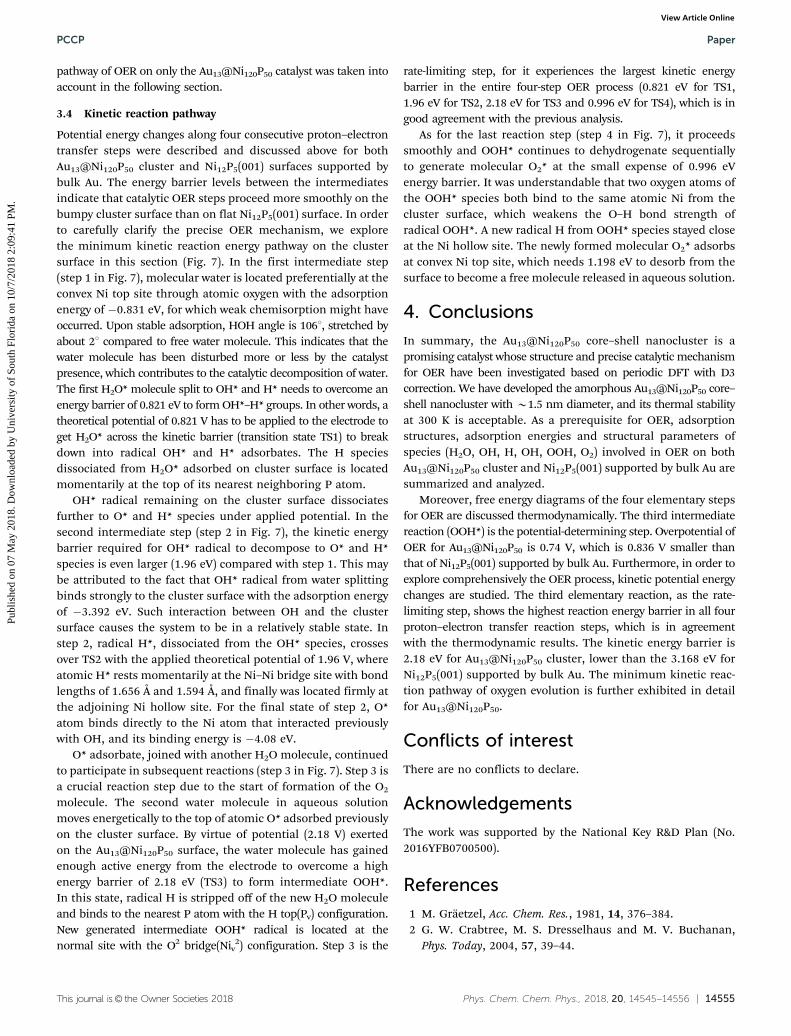
Fig. 7 Minimum kinetic reaction energy pathway along the four consecutive proton–electron transfer steps on the core–shell cluster surface for OER.The number above the arrows is the total energy difference between the former and latter configurations; a positive value denotes an uphill process. Theunit of energy is eV.
Paper PCCP
Publ
ishe
d on
07
May
201
8. D
ownl
oade
d by
Uni
vers
ity o
f So
uth
Flor
ida
on 1
0/7/
2018
2:0
9:41
PM
. View Article Online
This journal is© the Owner Societies 2018 Phys. Chem. Chem. Phys., 2018, 20, 14545--14556 | 14555
pathway of OER on only the Au13@Ni120P50 catalyst was taken intoaccount in the following section.
3.4 Kinetic reaction pathway
Potential energy changes along four consecutive proton–electrontransfer steps were described and discussed above for bothAu13@Ni120P50 cluster and Ni12P5(001) surfaces supported bybulk Au. The energy barrier levels between the intermediatesindicate that catalytic OER steps proceed more smoothly on thebumpy cluster surface than on flat Ni12P5(001) surface. In orderto carefully clarify the precise OER mechanism, we explorethe minimum kinetic reaction energy pathway on the clustersurface in this section (Fig. 7). In the first intermediate step(step 1 in Fig. 7), molecular water is located preferentially at theconvex Ni top site through atomic oxygen with the adsorptionenergy of �0.831 eV, for which weak chemisorption might haveoccurred. Upon stable adsorption, HOH angle is 1061, stretched byabout 21 compared to free water molecule. This indicates that thewater molecule has been disturbed more or less by the catalystpresence, which contributes to the catalytic decomposition of water.The first H2O* molecule split to OH* and H* needs to overcome anenergy barrier of 0.821 eV to form OH*–H* groups. In other words, atheoretical potential of 0.821 V has to be applied to the electrode toget H2O* across the kinetic barrier (transition state TS1) to breakdown into radical OH* and H* adsorbates. The H speciesdissociated from H2O* adsorbed on cluster surface is locatedmomentarily at the top of its nearest neighboring P atom.
OH* radical remaining on the cluster surface dissociatesfurther to O* and H* species under applied potential. In thesecond intermediate step (step 2 in Fig. 7), the kinetic energybarrier required for OH* radical to decompose to O* and H*species is even larger (1.96 eV) compared with step 1. This maybe attributed to the fact that OH* radical from water splittingbinds strongly to the cluster surface with the adsorption energyof �3.392 eV. Such interaction between OH and the clustersurface causes the system to be in a relatively stable state. Instep 2, radical H*, dissociated from the OH* species, crossesover TS2 with the applied theoretical potential of 1.96 V, whereatomic H* rests momentarily at the Ni–Ni bridge site with bondlengths of 1.656 Å and 1.594 Å, and finally was located firmly atthe adjoining Ni hollow site. For the final state of step 2, O*atom binds directly to the Ni atom that interacted previouslywith OH, and its binding energy is �4.08 eV.
O* adsorbate, joined with another H2O molecule, continuedto participate in subsequent reactions (step 3 in Fig. 7). Step 3 isa crucial reaction step due to the start of formation of the O2
molecule. The second water molecule in aqueous solutionmoves energetically to the top of atomic O* adsorbed previouslyon the cluster surface. By virtue of potential (2.18 V) exertedon the Au13@Ni120P50 surface, the water molecule has gainedenough active energy from the electrode to overcome a highenergy barrier of 2.18 eV (TS3) to form intermediate OOH*.In this state, radical H is stripped off of the new H2O moleculeand binds to the nearest P atom with the H top(Pv) configuration.New generated intermediate OOH* radical is located at thenormal site with the O2 bridge(Niv
2) configuration. Step 3 is the
rate-limiting step, for it experiences the largest kinetic energybarrier in the entire four-step OER process (0.821 eV for TS1,1.96 eV for TS2, 2.18 eV for TS3 and 0.996 eV for TS4), which is ingood agreement with the previous analysis.
As for the last reaction step (step 4 in Fig. 7), it proceedssmoothly and OOH* continues to dehydrogenate sequentiallyto generate molecular O2* at the small expense of 0.996 eVenergy barrier. It was understandable that two oxygen atoms ofthe OOH* species both bind to the same atomic Ni from thecluster surface, which weakens the O–H bond strength ofradical OOH*. A new radical H from OOH* species stayed closeat the Ni hollow site. The newly formed molecular O2* adsorbsat convex Ni top site, which needs 1.198 eV to desorb from thesurface to become a free molecule released in aqueous solution.
4. Conclusions
In summary, the Au13@Ni120P50 core–shell nanocluster is apromising catalyst whose structure and precise catalytic mechanismfor OER have been investigated based on periodic DFT with D3correction. We have developed the amorphous Au13@Ni120P50 core–shell nanocluster with B1.5 nm diameter, and its thermal stabilityat 300 K is acceptable. As a prerequisite for OER, adsorptionstructures, adsorption energies and structural parameters ofspecies (H2O, OH, H, OH, OOH, O2) involved in OER on bothAu13@Ni120P50 cluster and Ni12P5(001) supported by bulk Au aresummarized and analyzed.
Moreover, free energy diagrams of the four elementary stepsfor OER are discussed thermodynamically. The third intermediatereaction (OOH*) is the potential-determining step. Overpotential ofOER for Au13@Ni120P50 is 0.74 V, which is 0.836 V smaller thanthat of Ni12P5(001) supported by bulk Au. Furthermore, in order toexplore comprehensively the OER process, kinetic potential energychanges are studied. The third elementary reaction, as the rate-limiting step, shows the highest reaction energy barrier in all fourproton–electron transfer reaction steps, which is in agreementwith the thermodynamic results. The kinetic energy barrier is2.18 eV for Au13@Ni120P50 cluster, lower than the 3.168 eV forNi12P5(001) supported by bulk Au. The minimum kinetic reac-tion pathway of oxygen evolution is further exhibited in detailfor Au13@Ni120P50.
Conflicts of interest
There are no conflicts to declare.
Acknowledgements
The work was supported by the National Key R&D Plan (No.2016YFB0700500).
References
1 M. Graetzel, Acc. Chem. Res., 1981, 14, 376–384.2 G. W. Crabtree, M. S. Dresselhaus and M. V. Buchanan,
Phys. Today, 2004, 57, 39–44.
PCCP Paper
Publ
ishe
d on
07
May
201
8. D
ownl
oade
d by
Uni
vers
ity o
f So
uth
Flor
ida
on 1
0/7/
2018
2:0
9:41
PM
. View Article Online
14556 | Phys. Chem. Chem. Phys., 2018, 20, 14545--14556 This journal is© the Owner Societies 2018
3 D. G. Nocera, Acc. Chem. Res., 2012, 45, 767–776.4 J. A. Turner, Science, 1999, 285, 687–689.5 M. G. Walter, E. L. Warren, J. R. McKone, S. W. Boettcher,
Q. Mi, E. A. Santori and N. S. Lewis, Chem. Rev., 2010, 110,6446–6473.
6 S. Lewis and D. G. Nocera, Proc. Natl. Acad. Sci. U. S. A., 2006,103, 15729–15735.
7 J. Luo, J. Im, M. T. Mayer, M. Schreier, M. K. Nazeeruddin,N. G. Park, S. D. Tilley, H. Fan and M. Gratzel, Science, 2014,345, 1593–1596.
8 K. Zeng and D. Zhang, Prog. Energy Combust. Sci., 2010, 36,307–326.
9 W. T. Hong, M. Risch, K. A. Stoerzinger, A. Grimaud, J. Suntivichand S. Yang, Energy Environ. Sci., 2015, 8, 1404–1427.
10 Y. Wang, K. Jiang, H. Zhang, T. Zhou, J. Wang, W. Wei, Z. Yang,X. Sun, W. B. Cai and G. Zheng, Adv. Sci., 2015, 2, 1500003.
11 M. W. Kanan and D. G. Nocera, Science, 2008, 321, 1072–1075.12 W. J. Youngblood, S. A. Lee, Y. Kobayashi, E. A. Hernandez-
Pagan, P. G. Hoertz, T. A. Moore, A. L. Moore, D. Gust andT. E. Mallouk, J. Am. Chem. Soc., 2009, 131, 926–927.
13 T. Y. Ma, S. Dai, M. Jaroniec and S. Z. Qiao, J. Am. Chem.Soc., 2014, 136, 13925–13931.
14 J. Yano, J. Kern, K. Sauer, M. J. Latimer, Y. Pushkar,J. Biesiadka, B. Loll, W. Saenger, J. Messinger, A. Zouniand V. K. Yachandra, Science, 2006, 314, 821–825.
15 S. Chen, J. Duan, M. Jaroniec and S. Z. Qiao, Angew. Chem.,Int. Ed., 2013, 52, 13567–13570.
16 L. Duan, F. Bozoglian, S. Mandal, B. Stewart, T. Privalov,A. Llobet and L. Sun, Nat. Chem., 2012, 4, 418–423.
17 D. Li, H. Baydoun, C. N. Verani and S. L. Brock, J. Am. Chem.Soc., 2016, 138, 4006–4009.
18 Y. Lee, J. Suntivich, K. J. May, E. E. Perry and S. Yang, J. Am.Chem. Soc., 2012, 3, 399–404.
19 T. Takashima, K. Hashimoto and R. Nakamura, J. Am. Chem.Soc., 2012, 134, 1519–1527.
20 K. L. Pickrahn, S. W. Park, Y. Gorlin, H. Lee, T. F. Jaramilloand S. F. Bent, Adv. Energy Mater., 2012, 2, 1269–1277.
21 T. L. Wee, B. D. Sherman, D. Gust, A. L. Moore, T. A. Moore,Y. Liu and J. C. Scaiano, J. Am. Chem. Soc., 2011, 133,16742–16745.
22 F. Jiao and H. Frei, Energy Environ. Sci., 2010, 3, 1018–1027.23 A. J. Esswein, Y. Surendranath, S. Y. Reece and D. G. Nocera,
Energy Environ. Sci., 2011, 4, 499–504.24 Y. Li, P. Hasin and Y. Wu, Adv. Mater., 2010, 22, 1926–1929.25 H. C. Chien, W. Y. Cheng, Y. H. Wang, T. Y. Wei and
S. Y. Lu, J. Mater. Chem., 2011, 21, 18180.26 J. Suntivich, K. J. May, H. A. Gasteiger, J. B. Goodenough
and S. Yang, Science, 2011, 334, 1383–1385.27 B. B. Cui, H. Lin, J. Li, X. Li, J. Yang and J. Tao, Adv. Funct.
Mater., 2008, 18, 1440–1447.28 R. N. Singh, D. Mishra, Anindita, A. S. K. Sinha and A. Singh,
Electrochem. Commun., 2007, 9, 1369–1373.29 Y. Xu, S. Duan, H. Li, M. Yang, S. Wang, X. Wang and
R. Wang, Nano Res., 2017, 10, 3103–3112.30 L. A. Stern, L. Feng, F. Song and X. Hu, Energy Environ. Sci.,
2015, 8, 2347–2351.
31 A. Han, H. Chen, Z. Sun, J. Xu and P. Du, Chem. Commun.,2015, 51, 11626–11629.
32 P. Wang, F. Song, R. Amal, Y. H. Ng and X. Hu, Chem-SusChem, 2016, 9, 472–477.
33 M. Liu and J. Li, ACS Appl. Mater. Interfaces, 2016, 8, 2158–2165.34 C. C. Hou, S. Cao, W. F. Fu and Y. Chen, ACS Appl. Mater.
Interfaces, 2015, 7, 28412–28419.35 J. Chang, Y. Xiao, M. Xiao, J. Ge, C. Liu and W. Xing, ACS
Catal., 2015, 5, 6874–6878.36 M. Adriana, H. Zhu, Y. Yu, Q. Li, L. Zhou, D. Su, M. J. Kramer
and S. Sun, Angew. Chem., Int. Ed., 2015, 54, 9642–9645.37 M. Adriana, D. Su and S. Sun, Nanoscale, 2016, 8, 3244–3247.38 S. T. Oyama, J. Catal., 2003, 216, 343–352.39 G. Kresse and J. Furthmuller, Phys. Rev. B: Condens. Matter
Mater. Phys., 1996, 54, 11169–11186.40 J. P. Perdew, K. Burke and M. Ernzerhof, Phys. Rev. Lett.,
1996, 77, 3865–3868.41 P. E. Blochl, Phys. Rev. B: Condens. Matter Mater. Phys., 1994,
50, 17953–17979.42 S. Grimme, J. Antony, S. Ehrlich and H. Krieg, J. Chem. Phys.,
2010, 132, 154104.43 J. L. F. Da Silva, C. Stampfl and M. Scheffler, Phys. Rev. Lett.,
2003, 90, 066104.44 J. L. F. Da Silva, C. Stampfl and M. Scheffler, Phys. Rev. B:
Condens. Matter Mater. Phys., 2005, 72, 075424.45 G. Henkelman, B. P. Uberuaga and H. Jonsson, J. Chem.
Phys., 2000, 113, 9901–9904.46 Y. Ni, K. Liao and J. Li, CrystEngComm, 2010, 12, 1568.47 T. Tsuchiya and K. Kawamura, J. Chem. Phys., 2002, 116,
2121–2124.48 D. Fuks, M. V. Landau and M. Herskowitz, J. Phys. Chem. C,
2010, 114, 13313–13321.49 P. Tereshchuk and J. L. F. Da Silva, J. Phys. Chem. C, 2012,
116, 24695–24705.50 W. S. Benedict, N. Gailar and E. K. Plyler, J. Chem. Phys.,
1956, 24, 1139–1165.51 E. Skulason, V. Tripkovic, M. E. Bjorketun, S. Gudmundsdottir,
G. Karlberg, J. Rossmeisl, T. Bligaard, H. Jonsson andJ. K. Nørskov, J. Phys. Chem. C, 2010, 114, 18182–18197.
52 L. C. Seitz, C. F. Dickens, K. Nishio, Y. Hikita, J. Montoya,A. Doyle, C. Kirk, A. Vojvodic, H. Y. Hwang, J. K. Norskovand T. F. Jaramillo, Science, 2016, 353, 1011–1014.
53 I. C. Man, H. Y. Su, C. Federico, H. A. Hansen, J. I. Martınez,N. G. Inoglu, J. Kitchin, T. F. Jaramillo, J. K. Nørskov andJ. Rossmeisl, ChemCatChem, 2011, 3, 1159–1165.
54 X. Wang, H. Inada, L. Wu, Y. Zhu, Y. Choi, P. Liu, W. Zhouand R. R. Aszic, J. Am. Chem. Soc., 2009, 131, 17298–17302.
55 J. Wu, P. Li, Y. T. Pan, S. Warren, X. Yin and H. Yang, Chem.Soc. Rev., 2012, 41, 8066–8074.
56 G. Mills, M. S. Gordon and H. Metiu, J. Chem. Phys., 2003,118, 4198–4205.
57 A. Ruban, B. Hammer, P. Stoltze, H. L. Skriver andJ. K. Nørskov, J. Mol. Catal. A: Chem., 1997, 115, 421–429.
58 S. N. Rashkeev, A. R. Lupini, S. H. Overbury, S. J. Pennycookand S. T. Pantelides, Phys. Rev. B: Condens. Matter Mater.Phys., 2007, 76, 035438.
Paper PCCP
Publ
ishe
d on
07
May
201
8. D
ownl
oade
d by
Uni
vers
ity o
f So
uth
Flor
ida
on 1
0/7/
2018
2:0
9:41
PM
. View Article Online