Study of MDS Matrix used in Twofish AES (Advanced ...aarti/pubs/MDS.pdf · Study of MDS Matrix used...
23
Study of MDS Matrix used in Twofish AES (Advanced Encryption Standard) Algorithm and its VHDL Implementation Aarti Singh 1/EC/97
Transcript of Study of MDS Matrix used in Twofish AES (Advanced ...aarti/pubs/MDS.pdf · Study of MDS Matrix used...

Study of MDS Matrix used in Twofish AES (Advanced Encryption Standard) Algorithm
and its VHDL Implementation
Aarti Singh 1/EC/97

ACKNOWLEDGEMENT
I carried out this Project at CEERI (Central Electronic Engineering
Research Institute), Delhi. I am thankful to my advisor and guide Dr. Amrik Singh,
without whose support, this project would not have been possible. He introduced me
to this challenging and exciting topic and guided me throughout. I am also thankful
to Dr. S.P.S. Saini and Mr. Brijesh Joshi for their useful assistance and comments.
Also I take this opportunity to express my regards and sincere thanks to Dr. H.R.
Singh who assigned me to this project. I am also indebted to Dr. S.S. Aggarwal,
Head CEERI (D) for providing me the opportunity to work in their reputed institute
and extend some contribution to it. Last but not the least, I thank all CEERI staff for
helping me out with whatever I needed.
Aarti Singh
INTRODUCTION
Data Encryption has assumed a significant role in today’s world. With the
ever-increasing need to ensure security of data during communication, the
Encryption Algorithms need to be strengthened. The advances in crypt-analysis
further underscore the importance of having secure Algorithms. With this aim in
mind, the National Institute of Standards and Technology (NIST), responsible for
maintaining encryption standards in the U.S., gave a call for AES or the Advanced
Encryption Standard. Till date there are 5 contenders that have emerged successful
in the 3 round-conferences.
The five finalists:
1. Mars
2. RC6
3. Rjndael
4. Serpent 5. Twofish
This Project is an introduction to the AES candidate – Twofish. Twofish is named
such since it has two main diffusion elements, they are the MDS (Maximum
Distance Separable) matrix and the PHT (Pseudo Hadamard Transform). (Moreover
it is customary to name ciphers after sea-creatures and Twofish is the successor of
Blowfish.) This Project undertakes a deeper analysis of its most significant diffusion
element, the MDS matrix. A VHDL model for the hardware implementation of the
matrix is also proposed.
AES (Advanced Encryption Standard):
AES is the next-generation of Encryption Standard. It is basically an
improvement over the DES (Data Encryption Standard). One of its prerequisite is a
128-bit block cipher to replace the current 64-bit ciphers.
#eed for AES/a 128-bit block cipher: 1. The key used in various prevalent 64-bit ciphers like DES is too short for
acceptable commercial security requirements of today.
2. Recent advances in distributed key-search technique have made the earlier
ciphers prone to cryptanalytic attacks.
3. Ciphers like Triple-DES, which despite being 64-bit offer greater number of
rounds to meet the required security, are too slow.
4. Another disadvantage of 64-bit ciphers is that the 64-bit block length is open
to attacks when large amount of data are encrypted under the same key.
Twofish Characteristics:
• A 128-bit block cipher.
• Key lengths of 128 bits, 192 bits and 256 bits.
• No weak keys.
• Efficiency and speed on both, software ( PIII pro etc.) and
hardware ( smartcard etc.) platforms.
• Flexible design e.g.
o Accepts additional key lengths (all key lengths
up to 256 bits with leading zeros filled in).
o Implementable on variety of platforms.
o Suitable for stream-ciphering also.
o Also usable for hash function and MAC (Message
Authentication Codes)

Twofish Algorithm Block Structure:
P (128-bit plaintext)
Little-endian conversion
P0 P1 P2 P3
K0 K1 K2 K3 ] i/p whitening
R r, 2 Rr, 3
Fr, 0 << 1
Rr, 0
Fr, 1
Rr, 1 1 round
>> 1
15 more
rounds
K4 K5 K6 K 7 ] o/p whitening
C0 C1 C2 C3
Little-endian conversion
C (128-bit cipher text)
F
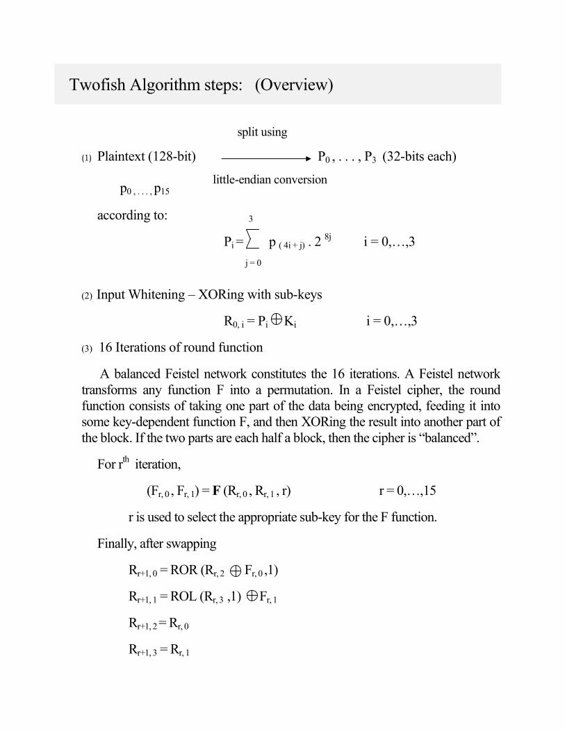
Twofish Algorithm steps: (Overview)
split using
(1) Plaintext (128-bit) P0 , . . . , P3 (32-bits each)
p0 , . . . , p15
little-endian conversion
according to: 3
Pi = p ( 4i + j) . 2 8j i = 0,…,3
j = 0
(2) Input Whitening – XORing with sub-keys
R0, i = Pi Ki i = 0,…,3
(3) 16 Iterations of round function
A balanced Feistel network constitutes the 16 iterations. A Feistel network
transforms any function F into a permutation. In a Feistel cipher, the round
function consists of taking one part of the data being encrypted, feeding it into
some key-dependent function F, and then XORing the result into another part of
the block. If the two parts are each half a block, then the cipher is “balanced”.
For rth iteration,
(Fr, 0 , Fr, 1) = F (Rr, 0 , Rr, 1 , r) r = 0,…,15
r is used to select the appropriate sub-key for the F function.
Finally, after swapping
Rr+1, 0 = ROR (Rr, 2 Fr, 0 ,1)
Rr+1, 1 = ROL (Rr, 3 ,1) Fr, 1
Rr+1, 2 = Rr, 0
Rr+1, 3 = Rr, 1

(4) Output Whitening – XORing with sub-key
Ci = R16, (i +2) mod 4 Ki +4 i = 0,…,3
(5) C0,…,C3 of ciphertext 128-bit ciphertext, ci
little-endian conversion
The reverse little-endian proceeds as:
ci = C [ i /4] mod 28
i = 0,…15
28(i mod 4)
Function F – is a key-dependent permutation on 64-bit values. It takes three
arguments: two input words R0 and R1, and the round number r used to select the
appropriate subkeys and produces F0 and F1 as the result.
F PHT
g
R0 T 0 F 0
K2r + 8
g
<< 8
R1 T1 F1
K2r + 9
T0 = g (R 0)
T1 = g (ROL (R1, 8))
F0 = (T0+T1+K2r + 8) mod 232
F1 = (T0+2T1+K2r + 9) mod 232
PHT (Pseudo-Hadamard Transform) is a simple mixing operation. This is the
second main diffusion element. Twofish uses a 32-bit PHT defined as:
a’ = (a+b) mod 232
b’ = (a+2b) mod 232
where a and b are inputs.
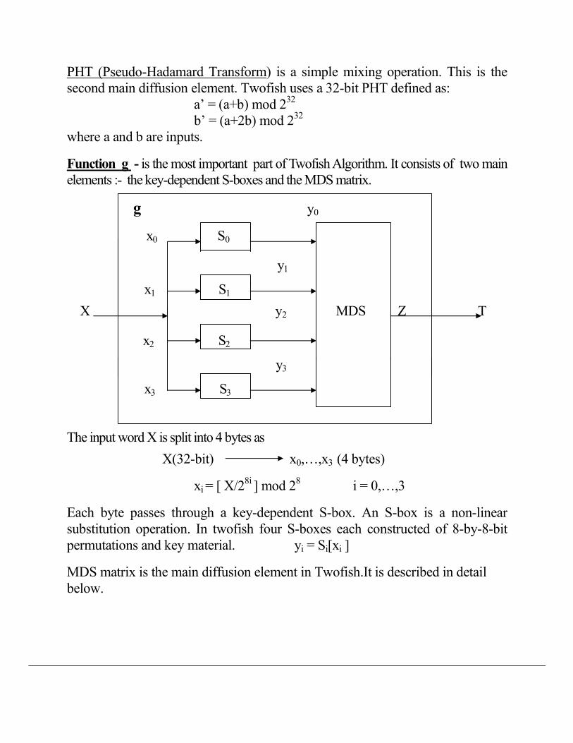
Function g - is the most important part of Twofish Algorithm. It consists of two main
elements :- the key-dependent S-boxes and the MDS matrix.
g y0
x0 S0
y1
x1 S1
X y2 MDS Z T
x2 S2
y3
x3 S3
The input word X is split into 4 bytes as
X(32-bit) x0,…,x3 (4 bytes)
xi = [ X/28i ] mod 2
8 i = 0,…,3
Each byte passes through a key-dependent S-box. An S-box is a non-linear
substitution operation. In twofish four S-boxes each constructed of 8-by-8-bit
permutations and key material. yi = Si[xi ]
MDS matrix is the main diffusion element in Twofish.It is described in detail
below.
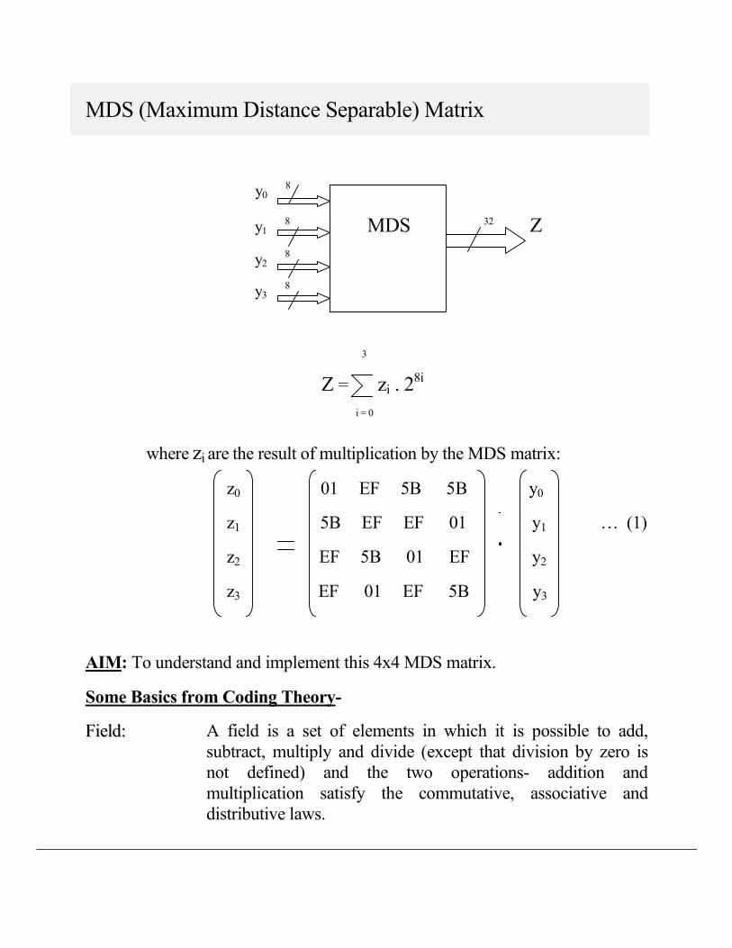
MDS (Maximum Distance Separable) Matrix
y0 8
y1 8 MDS
32 Z
y2 8
y3 8
3
Z = zi . 28i
i = 0
where zi are the result of multiplication by the MDS matrix:
z0 01 EF 5B 5B y0
z1 5B EF EF 01 y1 … (1)
z2 EF 5B 01 EF y2
z3 EF 01 EF 5B y3
AIM: To understand and implement this 4x4 MDS matrix.
Some Basics from Coding Theory-
FFiieelldd:: A field is a set of elements in which it is possible to add,
subtract, multiply and divide (except that division by zero is
not defined) and the two operations- addition and
multiplication satisfy the commutative, associative and
distributive laws.

GGaallooiiss FFiieelldd:: A field with q elements is called a finite field or Galois field,
and is denoted by GF(q). The field with minimum number of
elements i.e. two, 0 and 1, is called the binary field, GF(2).
EExxtteennddeedd
FFiieelldd::
An extended field of degree m over a finite field F has qm
elements if the base field has q elements.
Base field: GF(q) Extended field: GF(qm)
IIrrrreedduucciibbllee
PPoollyynnoommiiaall::
A polynomial p(x) that is not divisible by any other polynomial
except itself and 1.
MMoonniicc
PPoollyynnoommiiaall::
A polynomial that has the coefficient of the highest power of x
as1.
PPrriimmiittiivvee
PPoollyynnoommiiaall::
A monic irreducible polynomial.
The field formed by taking polynomials over a finite field F modulo p(x), where
p(x) is an irreducible polynomial of degree m, is also an extension field E of
degree m over F.
Twofish MDS uses the binary extended field GF(28)[x]/p(x) for computations
where p(x)=x8+x
6+x
5+x
3+1. ( GF(2
8)[x] represents a field where a field element
a = aixi , ai GF(2) and i=0…7, is identified with the byte value ai2
i .
Constructing the Galois field GF(28) requires a primitive polynomial p(x) of
degree 8 and a primitive element β which is a root of p(x). All elements of a
field can be expressed in terms of the primitive element.
CCooddee:: A block of k message symbols u = u1u2…un is encoded into a
codeword x = x1x2…xn (ui, xi _ GF(2
m)) where n > k; these
codewords form a code.
LLiinneeaarr CCooddee:: A code C is called a linear code if (v + w) is a word in C
whenever v and w are in C i.e. it is closed under addition.
LLeennggtthh ooff aa
ccooddee,, nn::
is the length of all its codewords i.e. the number of elements in
each codeword where each element may belong to any field qm.
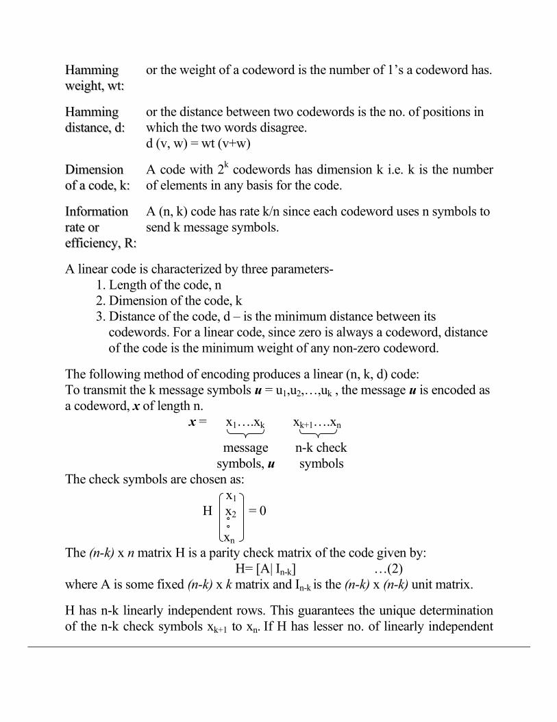
HHaammmmiinngg
wweeiigghhtt,, wwtt::
or the weight of a codeword is the number of 1’s a codeword has.
HHaammmmiinngg
ddiissttaannccee,, dd::
or the distance between two codewords is the no. of positions in
which the two words disagree.
d (v, w) = wt (v+w)
DDiimmeennssiioonn
ooff aa ccooddee,, kk::
A code with 2k codewords has dimension k i.e. k is the number
of elements in any basis for the code.
IInnffoorrmmaattiioonn
rraattee oorr
eeffffiicciieennccyy,, RR::
A (n, k) code has rate k/n since each codeword uses n symbols to
send k message symbols.
A linear code is characterized by three parameters-
1. Length of the code, n
2. Dimension of the code, k
3. Distance of the code, d – is the minimum distance between its
codewords. For a linear code, since zero is always a codeword, distance
of the code is the minimum weight of any non-zero codeword.
The following method of encoding produces a linear (n, k, d) code:
To transmit the k message symbols u = u1,u2,…,uk , the message u is encoded as
a codeword, x of length n.
x = x1….xk xk+1….xn
message n-k check
symbols, u symbols
The check symbols are chosen as:
x1
H x2 = 0
xn
The (n-k) x n matrix H is a parity check matrix of the code given by:
H= [A| In-k] …(2)
where A is some fixed (n-k) x k matrix and In-k is the (n-k) x (n-k) unit matrix.
H has n-k linearly independent rows. This guarantees the unique determination
of the n-k check symbols xk+1 to xn. If H has lesser no. of linearly independent
rows, then many such check symbols can be found. So, no. of linearly
independent rows is less than or equal to n-k.
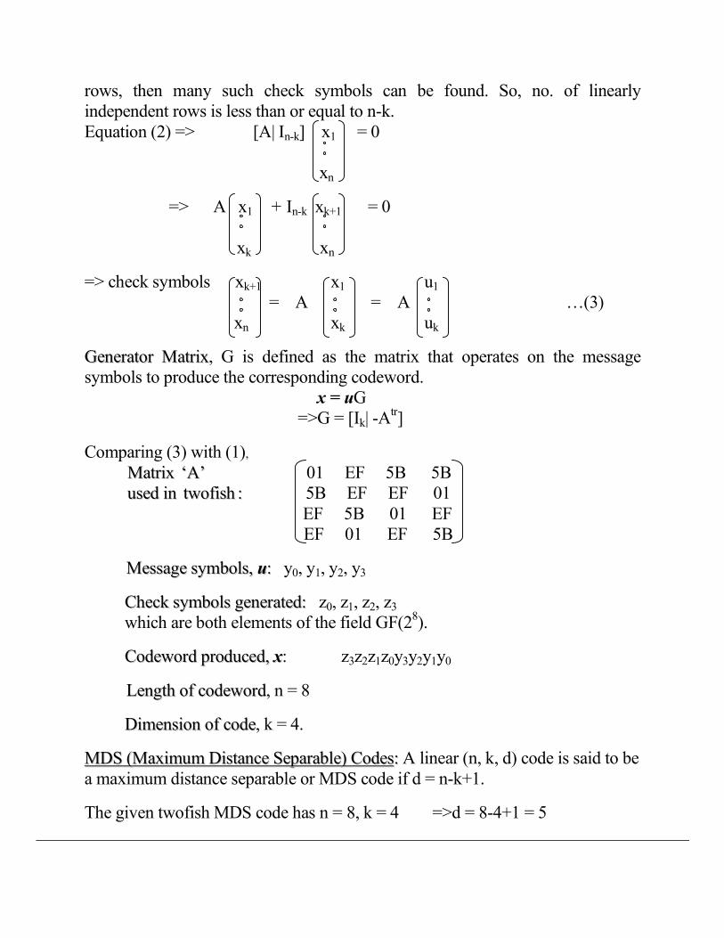
Equation (2) => [A| In-k] x1 = 0
xn
=> A x1 + In-k xk+1 = 0
xk xn
=> check symbols xk+1 x1 u1
= A = A …(3)
xn xk uk
GGeenneerraattoorr MMaattrriixx, G is defined as the matrix that operates on the message
symbols to produce the corresponding codeword.
x = uG
=>G = [Ik| -Atr]
Comparing (3) with (1),
MMaattrriixx ‘‘AA’’ 01 EF 5B 5B
uusseedd iinn ttwwooffiisshh :: 5B EF EF 01
EF 5B 01 EF
EF 01 EF 5B
MMeessssaaggee ssyymmbboollss,, uu:: y0, y1, y2, y3
CChheecckk ssyymmbboollss ggeenneerraatteedd:: z0, z1, z2, z3
which are both elements of the field GF(28).
CCooddeewwoorrdd pprroodduucceedd,, xx: z3z2z1z0y3y2y1y0
LLeennggtthh ooff ccooddeewwoorrdd, n = 8
DDiimmeennssiioonn ooff ccooddee, k = 4.
MMDDSS ((MMaaxxiimmuumm DDiissttaannccee SSeeppaarraabbllee)) CCooddeess:: A linear (n, k, d) code is said to be
a maximum distance separable or MDS code if d = n-k+1.
The given twofish MDS code has n = 8, k = 4 =>d = 8-4+1 = 5
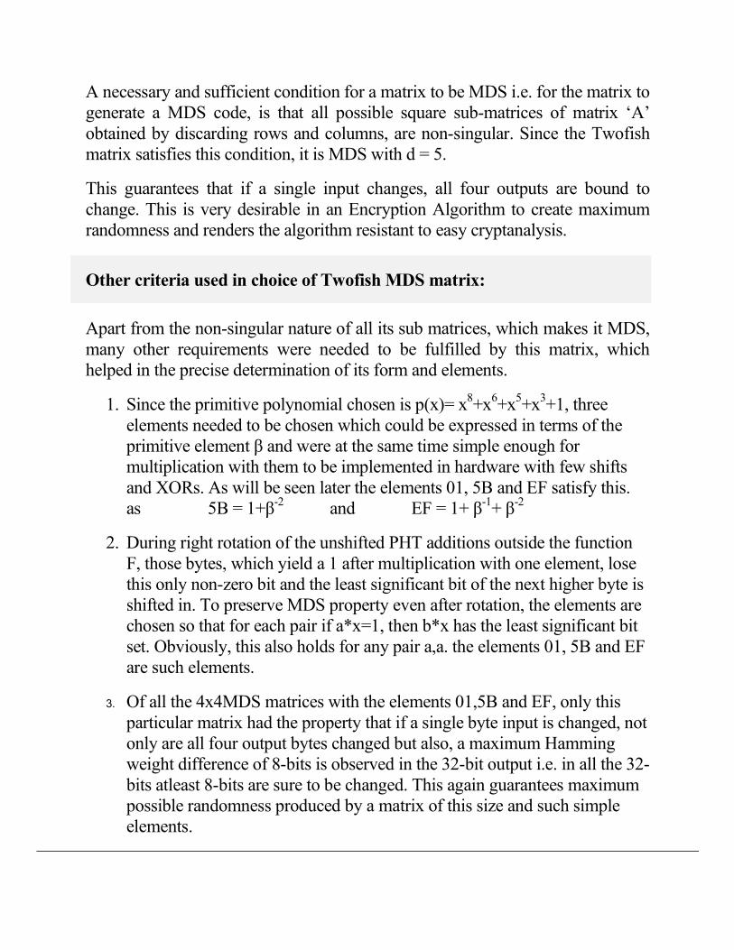
A necessary and sufficient condition for a matrix to be MDS i.e. for the matrix to
generate a MDS code, is that all possible square sub-matrices of matrix ‘A’
obtained by discarding rows and columns, are non-singular. Since the Twofish
matrix satisfies this condition, it is MDS with d = 5.
This guarantees that if a single input changes, all four outputs are bound to
change. This is very desirable in an Encryption Algorithm to create maximum
randomness and renders the algorithm resistant to easy cryptanalysis.
Other criteria used in choice of Twofish MDS matrix:
Apart from the non-singular nature of all its sub matrices, which makes it MDS,
many other requirements were needed to be fulfilled by this matrix, which
helped in the precise determination of its form and elements.
1. Since the primitive polynomial chosen is p(x)= x8+x
6+x
5+x
3+1, three
elements needed to be chosen which could be expressed in terms of the
primitive element β and were at the same time simple enough for
multiplication with them to be implemented in hardware with few shifts
and XORs. As will be seen later the elements 01, 5B and EF satisfy this.
as 5B = 1+β-2
and EF = 1+ β-1+ β
-2
2. During right rotation of the unshifted PHT additions outside the function
F, those bytes, which yield a 1 after multiplication with one element, lose
this only non-zero bit and the least significant bit of the next higher byte is
shifted in. To preserve MDS property even after rotation, the elements are
chosen so that for each pair if a*x=1, then b*x has the least significant bit
set. Obviously, this also holds for any pair a,a. the elements 01, 5B and EF
are such elements.
3. Of all the 4x4MDS matrices with the elements 01,5B and EF, only this
particular matrix had the property that if a single byte input is changed, not
only are all four output bytes changed but also, a maximum Hamming
weight difference of 8-bits is observed in the 32-bit output i.e. in all the 32-
bits atleast 8-bits are sure to be changed. This again guarantees maximum
possible randomness produced by a matrix of this size and such simple
elements.

Hardware Implementation of MDS matrix
In software, the MDS matrix can be implemented easily by a table look-up
procedure. However for hardware implementation, simple elements have been
chosen which can be implemented using a few shifts and XORs.
The twofish MDS matrix requires just 2 basic blocks - multiplication by
5B and by EF since multiplication by 01 is nothing but the number itself.
x 8 5B 8 5B.x x 8 EF 8 EF.x
The multiplication is carried out mod p(x), where p(x) = x8+x
6+x
5+x
3+1 is the
primitive element chosen. Now our aim is to simplify these multiplications so
that they can be implemented using a using a few shifts and XORs.
With the earlier defined correspondence, p(x) maps to 28+2
6+2
5+2
3+2
0
= 1 0110 1001
= 169 (H)
Here + represents addition modulo 2 i.e. XOR.
Also,
5B (H) = 0101 1011 = 26+2
4+2
3+2
1+2
0
EF (H) = 1110 1111 = 27+2
6+2
5+2
3+2
2+2
1+2
0
Therefore,
5B.x = ( 26+2
4+2
3+2
1+2
0 ).x
= 20.x + ( 2
6+2
4+2
3+2
1).x
= x + 2-2.x
+ ( 2
6+2
4+2
3+2
1+2
-2).x
= x + (x>>2) + 169(H).x
4
= x + (x>>2) +169(H).x0.20 +169(H).x1.2
1 +169(H).x2.2
2 +...+ 169(H).x7.2
7
4 4 4 4
Now, 169(H) is a 9-bit number and 169(H) is a 7-bit number. All multiplications
4
with 22 or more
make that term greater than 8-bits. Since multiplication is carried
out mod p(x) i.e. mod 169(H), all such terms come out to be zero.
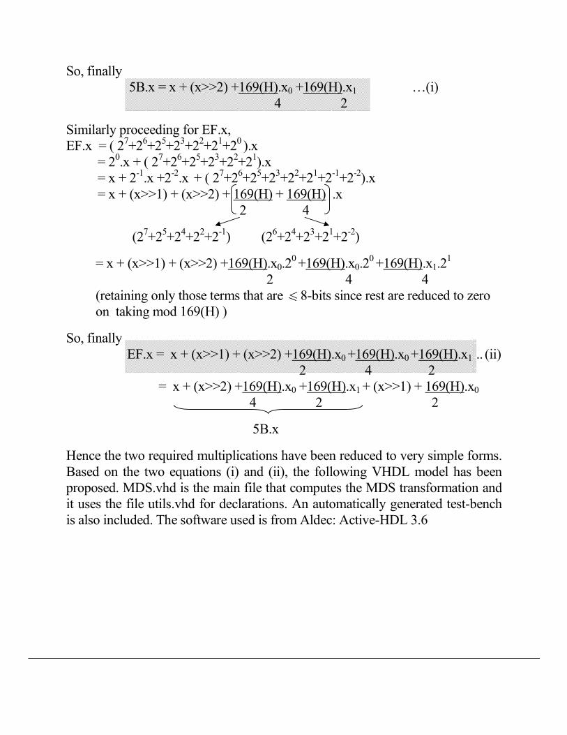
So, finally
5B.x = x + (x>>2) +169(H).x0 +169(H).x1 …(i)
4 2
Similarly proceeding for EF.x,
EF.x = ( 27+2
6+2
5+2
3+2
2+2
1+2
0 ).x
= 20.x + ( 2
7+2
6+2
5+2
3+2
2+2
1).x
= x + 2-1.x +2
-2.x
+ ( 2
7+2
6+2
5+2
3+2
2+2
1+2
-1+2
-2).x
= x + (x>>1) + (x>>2) + 169(H) + 169(H) .x
2 4
(27+2
5+2
4+2
2+2
-1) (2
6+2
4+2
3+2
1+2
-2)
= x + (x>>1) + (x>>2) +169(H).x0.20 +169(H).x0.2
0 +169(H).x1.2
1
2 4 4
(retaining only those terms that are < 8-bits since rest are reduced to zero
on taking mod 169(H) )
So, finally
EF.x = x + (x>>1) + (x>>2) +169(H).x0 +169(H).x0
+169(H).x1
.. (ii)
2 4 2
= x + (x>>2) +169(H).x0 +169(H).x1 + (x>>1) + 169(H).x0
4 2 2
5B.x
Hence the two required multiplications have been reduced to very simple forms.
Based on the two equations (i) and (ii), the following VHDL model has been
proposed. MDS.vhd is the main file that computes the MDS transformation and
it uses the file utils.vhd for declarations. An automatically generated test-bench
is also included. The software used is from Aldec: Active-HDL 3.6

1:library MDS; use MDS.utils.all; 2:--declaration to include utility package 3:entity MDS is 4: port(y:in input_data; 5: Z:out bit_vector(((input_data'length*byte'length) 6: -1)downto 0)); 7:end entity MDS;
8: 9:architecture behav of MDS is 10: constant set_up_time:time:=2ns; 11:begin
12: process is 13: variable z_temp:input_data; --stores z(0)..z(3) 14: variable temp:bit_vector(((input_data'length*
15: byte'length)-1)downto 0);
16: variable op:byte; 17: variable p,m:integer; 18: begin
19: wait for set_up_time; 20: for i in z_temp'range loop
21: z_temp(i):=x"00"; 22: for j in y'range loop
23: case MDS_matrix(i,j) is
24: when x"01"=> 25: op:=y(j);
26: when x"5B"=> 27: op:=op1(MDS_matrix(i,j),y(j)); 28: when x"EF"=>
29: op:=op2(MDS_matrix(i,j),y(j));
30: when others=>
31: report"inconsistency in MDS-matrix" 32: severity failure;
33: end case;
34: z_temp(i):=op xor z_temp(i); 35: end loop;
36: end loop;
37: p:=Z'high; 38: for k in z_temp'reverse_range loop
39: m:=p-(byte'length-1);
40: temp(p downto m):=z_temp(k); 41: p:=m-1;
42: end loop; 43: Z<=temp; --Z=z(3)z(2)z(1)z(0) 44: wait on y; 45: end process; 46:end architecture behav;
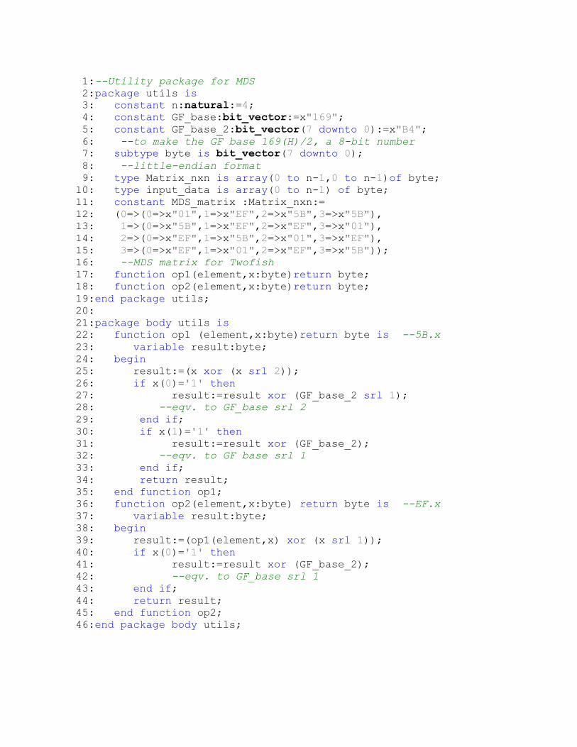
1:--Utility package for MDS 2:package utils is 3: constant n:natural:=4; 4: constant GF_base:bit_vector:=x"169"; 5: constant GF_base_2:bit_vector(7 downto 0):=x"B4"; 6: --to make the GF base 169(H)/2, a 8-bit number 7: subtype byte is bit_vector(7 downto 0);
8: --little-endian format 9: type Matrix_nxn is array(0 to n-1,0 to n-1)of byte; 10: type input_data is array(0 to n-1) of byte;
11: constant MDS_matrix :Matrix_nxn:=
12: (0=>(0=>x"01",1=>x"EF",2=>x"5B",3=>x"5B"), 13: 1=>(0=>x"5B",1=>x"EF",2=>x"EF",3=>x"01"),
14: 2=>(0=>x"EF",1=>x"5B",2=>x"01",3=>x"EF"),
15: 3=>(0=>x"EF",1=>x"01",2=>x"EF",3=>x"5B")); 16: --MDS matrix for Twofish 17: function op1(element,x:byte)return byte; 18: function op2(element,x:byte)return byte;
19:end package utils; 20:
21:package body utils is 22: function op1 (element,x:byte)return byte is --5B.x 23: variable result:byte;
24: begin 25: result:=(x xor (x srl 2));
26: if x(0)='1' then 27: result:=result xor (GF_base_2 srl 1); 28: --eqv. to GF_base srl 2 29: end if;
30: if x(1)='1' then
31: result:=result xor (GF_base_2); 32: --eqv. to GF base srl 1 33: end if;
34: return result; 35: end function op1; 36: function op2(element,x:byte) return byte is --EF.x 37: variable result:byte; 38: begin
39: result:=(op1(element,x) xor (x srl 1));
40: if x(0)='1' then 41: result:=result xor (GF_base_2); 42: --eqv. to GF_base srl 1 43: end if;
44: return result; 45: end function op2; 46:end package body utils;
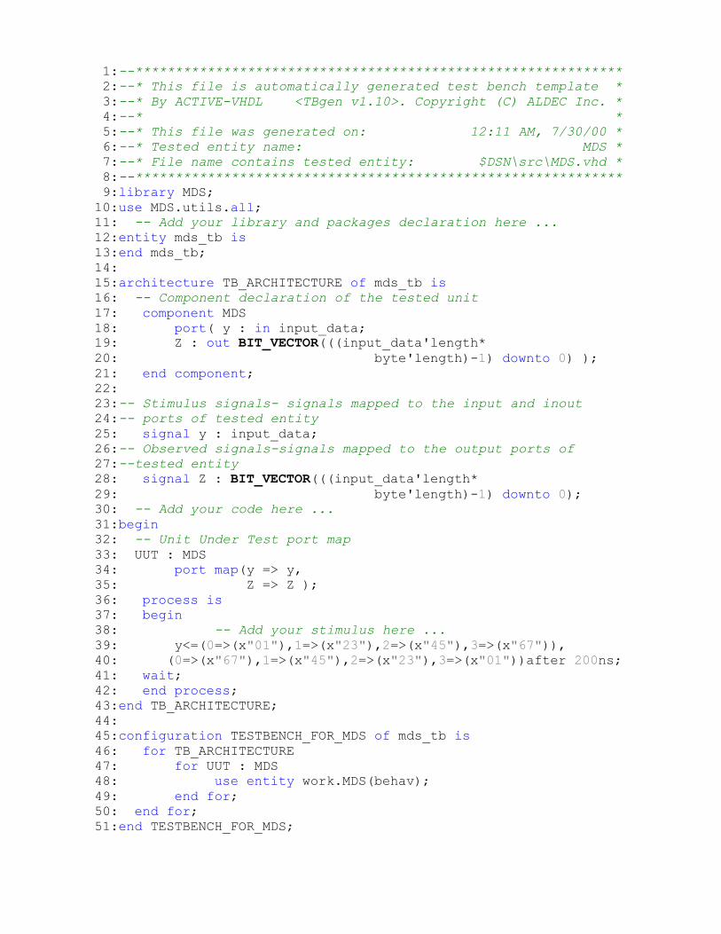
1:--************************************************************* 2:--* This file is automatically generated test bench template * 3:--* By ACTIVE-VHDL <TBgen v1.10>. Copyright (C) ALDEC Inc. * 4:--* * 5:--* This file was generated on: 12:11 AM, 7/30/00 * 6:--* Tested entity name: MDS * 7:--* File name contains tested entity: $DSN\src\MDS.vhd * 8:--************************************************************* 9:library MDS;
10:use MDS.utils.all; 11: -- Add your library and packages declaration here ... 12:entity mds_tb is
13:end mds_tb;
14: 15:architecture TB_ARCHITECTURE of mds_tb is 16: -- Component declaration of the tested unit 17: component MDS
18: port( y : in input_data; 19: Z : out BIT_VECTOR(((input_data'length* 20: byte'length)-1) downto 0) );
21: end component; 22: 23:-- Stimulus signals- signals mapped to the input and inout 24:-- ports of tested entity 25: signal y : input_data; 26:-- Observed signals-signals mapped to the output ports of 27:--tested entity 28: signal Z : BIT_VECTOR(((input_data'length* 29: byte'length)-1) downto 0); 30: -- Add your code here ... 31:begin 32: -- Unit Under Test port map 33: UUT : MDS 34: port map(y => y,
35: Z => Z );
36: process is 37: begin 38: -- Add your stimulus here ... 39: y<=(0=>(x"01"),1=>(x"23"),2=>(x"45"),3=>(x"67")), 40: (0=>(x"67"),1=>(x"45"),2=>(x"23"),3=>(x"01"))after 200ns;
41: wait;
42: end process; 43:end TB_ARCHITECTURE;
44: 45:configuration TESTBENCH_FOR_MDS of mds_tb is
46: for TB_ARCHITECTURE 47: for UUT : MDS 48: use entity work.MDS(behav);
49: end for; 50: end for;
51:end TESTBENCH_FOR_MDS;

An Alternative Circuit Design Approach to Hardware Implementation
From equation (1),
z0 = 01.y0 + EF.y1 + 5B.y2 + 5B.y3
z1 = 5B.y0 + EF.y1 + EF.y2 + 01.y3
z2 = EF.y0 + 5B.y1 + 01.y2 + EF.y3
z3 = EF.y0 + 01.y1 + EF.y2 + 5B.y3
Assuming data-bus to be of 8 bits, we’ll generate zi sequentially and
enable 8 bits of the 32-bit final register in turn.
Now, for each zi four multiplication blocks are required i.e. 01, EF, EF(5B for
z0) and 5B. This can be represented as:-
8 �
8 5B
Disabled for z0 8 zi
8 5B EF
8
EF
since as shown by eq.(ii),EF.x includes the terms for 5B.x.
To generate zi for i=0..3, the inputs required for the 4 blocks are as
follows:
Inputs for zi 01 5B 5B/EF EF
z0 y0 y2 y3 y1
z1 y3 y0 y2 y1
z2 y2 y1 y3 y0
z3 y1 y3 y2 y0
This can be achieved using multiplexers to choose the inputs to each block.
Let T0 be the control signal used to load data into the blocks. The overall
circuit diagram can now be drawn. (Note the use of the above � block). T7 is
the control signal that outputs each zi and clocks it into an output 32-bit latch.
Thus after all four zi are latched, the final output Z is available.
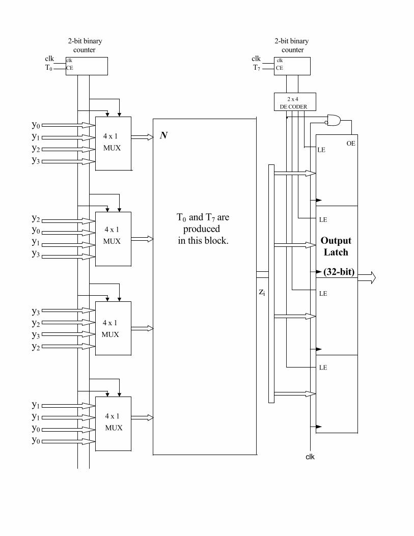
2-bit binary 2-bit binary
counter counter
clk clk clk clk
T0 CE T7 CE
2 x 4
DE CODER
y0
y1 4 x 1 �
y2 MUX LE OE
y3
y2 T0 and T7 are LE
y0 4 x 1 produced
y1 MUX in this block. Output
y3 Latch
(32-bit)
zi LE
y3
y2 4 x 1
y3 MUX
y2
LE
y1
y1 4 x 1
y0 MUX
y0
clk
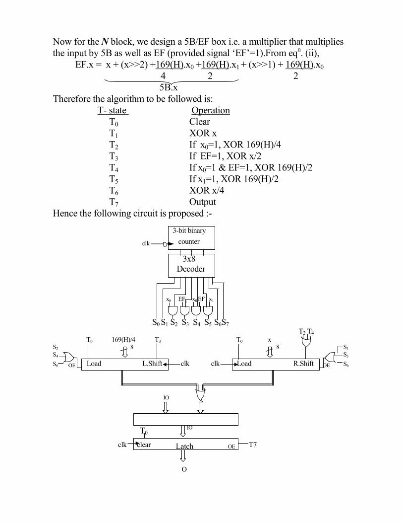
Now for the � block, we design a 5B/EF box i.e. a multiplier that multiplies
the input by 5B as well as EF (provided signal ‘EF’=1).From eqn. (ii),
EF.x = x + (x>>2) +169(H).x0 +169(H).x1 + (x>>1) + 169(H).x0
4 2 2
5B.x
Therefore the algorithm to be followed is:
T- state Operation
T0 Clear
T1 XOR x
T2 If x0=1, XOR 169(H)/4
T3 If EF=1, XOR x/2
T4 If x0=1 & EF=1, XOR 169(H)/2
T5 If x1=1, XOR 169(H)/2
T6 XOR x/4
T7 Output
Hence the following circuit is proposed :-
3-bit binary
clk counter
3x8
Decoder
x0 EF x0 EF x1
S0 S1 S2 S3 S4 S5 S6S7 T2 T4 T0 169(H)/4 T3 T0 x
S2 8 8 S1
S4 S3
S6 OE Load L.Shift clk clk Load R.Shift OE
S6
IO
T0
IO
clk clear Latch OE T7
O

CONCLUSION
The study of the AES candidate - Twofish, helped to gain some insight
into the present-day requirements of commercial security. With special
emphasis on the MDS (Maximum Distance Separable) matrix, the
application of coding theory elements in Encryption Algorithm was seen. The
importance of MDS codes in producing diffusion was analysed and this
revealed the significance of maximum diffusion in preventing crypt-analytic
attacks.
Finally, a hardware implementable VHDL model was proposed which
could be used to observe outputs that conformed the expected results from
theory.
References:
1. Twofish Encryption Algorithm - A 128-bit Block Cipher
By Bruce Schneier, John Kelsey, Doug Whiting, David Wagner,
Chris Hall, Niels Ferguson
2. The Theory of Error-Correcting Codes
By N.J.A. Sloane and F.J. Mac Williams
3. Coding Theory-The Essentials
By D.G.Hoffman, D.A.Leonard, C.C.Lindner, K.T.Phelps,
C.A.Rodger, J.R.Wall
4. The Designer’s Guide to VHDL
By Peter J. Ashenden
5. www.nist.gov/aes
6. www.counterpane.com/twofish
![Organiza - aec.es · AES Blowfish DES (internal mechanics, Diffie–Hellman – DSS – ElGamal - RSA Triple DES) Serpent Twofish [S/MIME – PGP -TLP-SSL (web) – SSH] (usan internamente](https://static.fdocuments.in/doc/165x107/603dad1e1683ab358b17b777/organiza-aeces-aes-blowfish-des-internal-mechanics-diffieahellman-a-dss.jpg)