Study of Lithium Battery Thermal Effect on Battery and ... · The results show battery sizing...
15
Journal of Engineering Technology Volume 6, Special Issue on Technology Innovations and Applications Oct. 2017, PP. 85-99 85 Study of Lithium Battery Thermal Effect on Battery and Hybrid Battery/Ultra-Capacitor Sizing for an Electric Vehicle Masoud Masih-Tehrani and Rambod Yahyaei Vehicle Dynamical Systems Research Laboratory, School of Automotive Engineering, Iran University of Science and Technology, Tehran, Iran Abstract: A thermal-based cost function is proposed to optimize the lithium battery size of an electric vehicle (conventional battery-based energy storage system or hybrid battery/ultra-capacitor energy storage system) in this paper. The proposed cost function is determined the battery lifetime with considering both the battery current and battery temperature, besides the overall cost of energy storage system. The studied energy storage systems are a conventional battery-based energy storage system and a hybrid energy storage system (HESS) (battery/ultra-capacitor). In HESS case, the effect of ultra-capacitor (UC) adding is moderating the battery current directly and battery temperature indirectly. The constraints of the optimum energy storage system sizing problem are the vehicle performance (e.g., driving cycle tracking and vehicle range). In this paper As a case study, an electric motorcycle modeled. The results show battery sizing should be redesign when the battery thermal model consider. Also, battery life decreases, and a battery temperature rise and when the ambient temperature growth, vehicle range increases. On the other hand, a lighter and cheaper cooling system could use in HESS in comparison with the ESS. Finally, the battery life improvement for a HESS is more noticeable when the battery thermal model used as compared with the case that the battery thermal model is disabled. Keywords: Lithium battery thermal model, Hybrid Energy Storage System, Battery sizing, Electric motorcycle 1. Introduction Energy wasting is an important issue in the vehicle [1]. Electric and hybrid vehicles [2] are an attractive research subject in the last decades [3], because of efficiency and the regenerative braking ability. The battery, as the energy storage system (ESS) of an electric vehicle, is a significant component of the EV [4]. A high portion of the EV cost is related to the battery cost [5]. Also, the battery life is finite, and it should be replaced after degradation [6]. Therefore, proper battery sizing and systematic design can improve the cost advantages of the EV [7]. For a cell sizing process, the vehicle powertrain model and a precise battery model are used. There are some EV powertrain models are developed recently, such as ADVISOR [8] and AVL/CRUISE [9]. In this paper, the package of Esfahanian et al. [10] is utilized for powertrain modeling. A famous and efficient approach to dynamical battery modeling is equivalent circuit [11]. On the other hand, many of the proposed battery models do not have a thermal model [12] (they are temperature independent); while the thermal model has a significant effect on the battery behavior [13] and maybe cause to explosion hazards (because of the thermal runaway phenomenon) [14]. Battery heat produced during the vehicle driving cycles should be handled to keep battery cell performance and good lifetime [15]. On the other hand, the effect of temperature on the fulfillment of a system is also proofed in many applications, such as the catalyst of a four-stroke engine [16]. Nelson et al. studied on the battery sizing for a plug-in hybrid electric vehicle [17]. They to look at the price for the thermal management system and increase battery lifetime investigate the effect of the designed system. However, the thermal model was not at the core of the battery sizing process [17]. Correa et al. developed a sizing method for the battery in a fuel cell vehicle. They did not concentrate on the battery temperature in their sizing process [18]. Colzi et al. proposed three items for battery sizing for a range
Transcript of Study of Lithium Battery Thermal Effect on Battery and ... · The results show battery sizing...

Journal of Engineering Technology Volume 6, Special Issue on Technology Innovations and Applications Oct. 2017, PP. 85-99
85
Study of Lithium Battery Thermal Effect on Battery and Hybrid
Battery/Ultra-Capacitor Sizing for an Electric Vehicle
Masoud Masih-Tehrani and Rambod Yahyaei
Vehicle Dynamical Systems Research Laboratory, School of Automotive Engineering, Iran University of
Science and Technology, Tehran, Iran
Abstract: A thermal-based cost function is proposed to optimize the lithium battery size of an electric vehicle
(conventional battery-based energy storage system or hybrid battery/ultra-capacitor energy storage system) in
this paper. The proposed cost function is determined the battery lifetime with considering both the battery
current and battery temperature, besides the overall cost of energy storage system. The studied energy storage
systems are a conventional battery-based energy storage system and a hybrid energy storage system (HESS)
(battery/ultra-capacitor). In HESS case, the effect of ultra-capacitor (UC) adding is moderating the battery
current directly and battery temperature indirectly. The constraints of the optimum energy storage system
sizing problem are the vehicle performance (e.g., driving cycle tracking and vehicle range). In this paper As a
case study, an electric motorcycle modeled. The results show battery sizing should be redesign when the
battery thermal model consider. Also, battery life decreases, and a battery temperature rise and when the
ambient temperature growth, vehicle range increases. On the other hand, a lighter and cheaper cooling system
could use in HESS in comparison with the ESS. Finally, the battery life improvement for a HESS is more
noticeable when the battery thermal model used as compared with the case that the battery thermal model is
disabled.
Keywords: Lithium battery thermal model, Hybrid Energy Storage System, Battery sizing, Electric
motorcycle
1. Introduction
Energy wasting is an important issue in the vehicle [1]. Electric and hybrid vehicles [2] are an attractive
research subject in the last decades [3], because of efficiency and the regenerative braking ability. The battery,
as the energy storage system (ESS) of an electric vehicle, is a significant component of the EV [4]. A high
portion of the EV cost is related to the battery cost [5]. Also, the battery life is finite, and it should be replaced
after degradation [6]. Therefore, proper battery sizing and systematic design can improve the cost advantages
of the EV [7].
For a cell sizing process, the vehicle powertrain model and a precise battery model are used. There are
some EV powertrain models are developed recently, such as ADVISOR [8] and AVL/CRUISE [9]. In this
paper, the package of Esfahanian et al. [10] is utilized for powertrain modeling. A famous and efficient
approach to dynamical battery modeling is equivalent circuit [11]. On the other hand, many of the proposed
battery models do not have a thermal model [12] (they are temperature independent); while the thermal model
has a significant effect on the battery behavior [13] and maybe cause to explosion hazards (because of the
thermal runaway phenomenon) [14]. Battery heat produced during the vehicle driving cycles should be
handled to keep battery cell performance and good lifetime [15]. On the other hand, the effect of temperature
on the fulfillment of a system is also proofed in many applications, such as the catalyst of a four-stroke engine
[16].
Nelson et al. studied on the battery sizing for a plug-in hybrid electric vehicle [17]. They to look at the
price for the thermal management system and increase battery lifetime investigate the effect of the designed
system. However, the thermal model was not at the core of the battery sizing process [17]. Correa et al.
developed a sizing method for the battery in a fuel cell vehicle. They did not concentrate on the battery
temperature in their sizing process [18]. Colzi et al. proposed three items for battery sizing for a range

Journal of Engineering Technology Volume 6, Special Issue on Technology Innovations and Applications Oct. 2017, PP. 85-99
86
extender electric vehicle: “mean daily traveled distance,” “total-life battery range,” and “the satisfaction of the
worst-case”. They did not mention the battery thermal behavior [19].
Hybrid energy storage systems (HESS) are introduced from 1989 [20] and they attracted considerable
attention. Fig1 shows the paper trends about the HESS (with these keywords: “Hybrid Energy Storage,”
“Hybrid Power Systems,” “Hybrid Energy System,” “Hybrid Energy Storage Systems”), which is indexed
from 1987 until now, in “scopus.com.” This figure presents the high attention to this subject in the last decade.
Wu et al. worked on a hybrid solar-battery design and management [21]. Ruiz-Cortes et al. studied on the
HESS for residential application [22]. Bartholomäus et al. proposed a Model predictive control for power-
sharing between battery and supercapacitor in a HESS [23]. In these works and much same as them, the
battery temperature and thermal behavior are not determined in the HESS sizing and control design process.
In this paper, the combination of battery and UC is assumed as the HESS [24]. The primary target of this
arrangement is to moderate the battery current to improve the battery lifetime [25]. An unaware point about
HESS is that the battery current reduction can reduce the battery temperature and improve the battery thermal
(cooling) system. Therefore, the battery lifetime maybe increases due to the lower battery temperature, in
addition to the effect of the lower battery current.
Fig1. HESS paper trends (in scopus.com)
The next section is about lithium battery modeling, especially about battery thermal model. In section 3,
the case study of this paper will be introduced In this article; an electric motorcycle is investigated in the FTP
driving cycle. After that, the HESS modeling and sizing will be discussed.
2. Lithium battery modeling
The lithium battery model consists of an equivalent electrical circuit, which has a dynamic model of this
energy storage system. The lithium battery model is implemented in MATLAB/Simulink software (Fig2).
Fig2. Lithium battery dynamic model in MATLAB/Simulink [26]
The equations of Fig2 are as follows [27]:
o Discharge model ( ):

Journal of Engineering Technology Volume 6, Special Issue on Technology Innovations and Applications Oct. 2017, PP. 85-99
87
(1)
o Charge model ( ):
(2)
where:
is nonlinear voltage (V).
is constant voltage (V).
is polarization resistance ( ).
is low-frequency current dynamics (A).
is battery current (A).
is extracted capacity (Ah).
is maximum battery capacity (Ah).
is exponential voltage (V).
is exponential capacity (Ah−1
).
The battery model information is listed in Table 1. As seen in this Table, the model parameters of the
LiFePO4 cell are determined by Omar et al. [28] (3rd
column) and are scaled for the case study battery pack in
the 4th column.
Table 1: Lithium battery (LiFePO4) parameters
Items Units Values for one
LiFePO4 cell [28]
Values for battery
pack
(case study)
Nominal voltage V 3.3 72.6
Rated capacity Ah 2.3 33.8
Battery response time s 30 30
Maximum capacity Ah 2.3 33.8
Cut-off voltage V 2.475 54.45
Fully charged voltage V 3.748 82.456
Nominal discharge current A 2.3 130.13
Internal resistance 0.014 0.0152
Capacity at nominal voltage Ah 2.25 33.0652
The effect of temperature on the model parameters is represented by these equations [26].
o Discharge model ( ):
(3)
(4)
o Charge model ( ):
(5)
(6)
(7)
(8)
(9)
(10)
where:
is nominal ambient temperature (K).
is the cell or internal temperature (K).
is ambient temperature (K).

Journal of Engineering Technology Volume 6, Special Issue on Technology Innovations and Applications Oct. 2017, PP. 85-99
88
is reversible voltage temperature coefficient (V/K).
is Arrhenius rate constant for the polarization resistance.
is Arrhenius rate constant for the internal resistance.
is maximum capacity temperature coefficient (Ah/K).
The cell or internal temperature, , at any given time, , is expressed as:
(11)
where:
is thermal resistance, cell to ambient (°C/W).
is the thermal time constant, cell to ambient (s).
is the overall heat generated (W) during charge/discharge process and is given by
(12)
The generalized life model as a function of the C-rate (ratio of the battery current to its capacity) is
proposed by Wang et al. [29] as follows:
(13)
where is the capacity loss in percent, is the pre-exponential factor and is a function of
(Table 2), is the gas constant, is the absolute temperature, and is the Ah-throughout which is
expressed as . Table 2: Values of with respect to the C-rate [29]
C-rate C/2 2C 6C 10C
Values 31630 21681 12934 15512
The life capacity (Ah) of the 2.6 Ah LiFePO4 battery cell for different battery currents are calculated using
Equation (13). The life capacity is defined as the amount of capacity that the battery can provide at a
particular current before its capacity reaches 20% [30].
The driving cycle capacity loss ( ) is given by Equation (4) [30].
(14)
where is the battery current at th time step and varies from zero to the driving cycle duration ( ). is
the time step for the calculations and is the life capacity and is a function of .
3. Case study (electric motorcycle)
As a case study, an electric motorcycle is examined in FTP driving cycle [31] (Fig3).
Fig3. FTP driving cycle (speed vs. time curve)
Main specifications and characteristics of the electric motorcycle and its powertrain are presented in tables
3 and 4, respectively.

Journal of Engineering Technology Volume 6, Special Issue on Technology Innovations and Applications Oct. 2017, PP. 85-99
89
Table 3: Electric motorcycle specifications
Items Units Values
Total mass (with driver) kg 250
Rolling resistance coefficient - 0.003
Drag coefficient - 0.4
Frontal area m2 0.6
Tire radius m 0.24
Table 4: Powertrain specifications of the electric motorcycle
System Item Units Values
High voltage
bus Voltage V 70
Traction
motors
Power kW 6
(peak 12)
Torque Nm 70
(peak 140)
Battery pack
Type -
286
LiFePO4
cells
(22 series
13 parallel)
Voltage V 72.6
Capacit
y Ah 33.8
Cycle
life
cycle
s 2000
The powertrain model is similar to the proposed models of Esfahanian et al. [10]. The performance of the
designed battery pack is listed in Table 5. In this calculation, the thermal model of battery is neglected, and
the battery temperature is assumed 25oC (for battery life determination). As seen in this table, the driving
cycle tracking error is very low, and the vehicle range is about 100 km (acceptable). The number of the
parallel battery (capacity) can be resized to adopt the vehicle range and battery life. It is evident that if the
battery capacity is rising, the vehicle (motorcycle) range would be increased. However, the added weight of
the bigger battery maybe hurt the vehicle range. On the other hand, the larger battery has a lower
with a specific battery current; therefore, the battery life would be increased. Because of the battery life is
lower than 10 years, the battery should be replaced one time and the overall cost of the battery is twice of the
initial battery cost.
Table 5: The performance of the designed battery pack without thermal model in 25oC
Tracking error
(km/h)
Vehicle range
(km) Initial cost (USD) Battery life (year)
10-year overall
cost (USD)
0.18 99.23 1250 6.08 2500
If the performance of Table 5 is recalculated in other ambient temperature, three first columns of that table
are not varied (the thermal model is not activated). Fig4 shows the battery life and overall cost vs. ambient
temperature for the designed battery pack without a thermal model. As shown in this figure, in a warm
environment (more than 25oC), the 10-year overall battery cost would be greater than 2500 USD, because the
battery life is lower than five years and the battery replacement exceeds one time during ten years.

Journal of Engineering Technology Volume 6, Special Issue on Technology Innovations and Applications Oct. 2017, PP. 85-99
90
Fig4. Battery life and overall cost vs. ambient temperature for the designed battery pack without thermal
model
Battery current, battery temperature and battery life loss for 13 parallel battery pack, with and without
battery thermal models are shown in Fig5. As presented here, the battery current for both models is very
similar. However, the battery temperature of the battery thermal model is higher than of the battery model
without thermal modeling. Therefore, the battery life loss (down figure) of the battery with the thermal model
is greater than another model.
Fig5. Battery current (up left figure), battery temperature (upright figure) and battery life loss (down figure)
for 13 parallel battery pack, with and without battery thermal models
Considering the battery thermal model maybe affect the battery sizing. The performance of the designed
battery pack with a thermal model in 25oC is listed in Table 6. As seen in this table, the battery pack with 13
parallel branches have about 95 km vehicle (motorcycle) range, which is lower than previous case (100 km).
Therefore, the number of parallel battery branches should be resized to 14. In this case, the vehicle range
would be about 101 km. The bigger battery pack (14 parallel) is more expensive in comparison with the initial
design (initial and overall costs). However, both of the designed battery packs have good thermal performance
(6th column of Table 6).

Journal of Engineering Technology Volume 6, Special Issue on Technology Innovations and Applications Oct. 2017, PP. 85-99
91
Table 6: The performance of the battery pack with thermal model in 25oC
Number of battery
parallel
Vehicle range
(km)
Initial cost
(USD) Battery life (year)
10-year overall
cost (USD)
Maximum
battery
temperature
(oC)
13 94.81 1250 5.50 2500 26.00
14 101.21 1346 5.93 2692 25.39
Fig6 shows the battery temperature rise (oC) (solid line) and tracking error (km/h) (dashed line) vs. ambient
temperature for the resized pack (14 parallel branches). As seen in this figure, both of the performance is good
and acceptable.
Fig6. Battery temperature rise (
oC) and tracking error (km/h) vs. ambient temperature for resized pack (14
parallel branches)
Fig7 shows the vehicle (motorcycle) range (km) in different ambient temperature. As seen in this figure,
the vehicle range improved with an ambient temperature rising and are higher than 100 km, except in 15oC
ambient temperature. It is a reason that some of the battery thermal management systems have a warm-up sub-
system for working in cold environment.
Fig7. Vehicle range (km) vs. ambient temperature for resized pack (14 parallel branches)

Journal of Engineering Technology Volume 6, Special Issue on Technology Innovations and Applications Oct. 2017, PP. 85-99
92
Fig8 shows the battery life and overall cost vs. ambient temperature for the resized battery pack (14
parallel) with a thermal model. As shown in this figure, in a warm environment (more than 25oC), the 10-year
overall battery cost would be greater than 2500 USD, because the battery life is lower than five years and the
battery replacement exceeds one time during ten years. This figure’s trends are similar to the Fig4.
Fig8. Battery life and overall cost vs. ambient temperature for the resized battery pack (14 parallel)
4. Hybrid energy storage system
The proposed HESS in this paper is combined with a battery pack and a UC pack. The battery dynamics
model is discussed in Section 2. Here, the UC model and the HESS control system is introduced.
4.1 Ultra-capacitor model
Fig9 shows the equivalent circuit model of the UC [32] in MATLAB/Simulink.
Fig9. UC dynamic model in MATLAB/Simulink [33]
The UC output voltage is calculated using a Stern equation [34] Equation (15).
(15)
where
(16)
To model the self-discharge phenomenon, the UC electric charge is corrected as equations (17) and (18)
(when ):
(17)

Journal of Engineering Technology Volume 6, Special Issue on Technology Innovations and Applications Oct. 2017, PP. 85-99
93
(18)
The parameters , , and are the rates of change of the UC voltage during time intervals ( , ),
( , ), and ( , ) respectively (Fig10).
Fig10. An overview of some parameters of UC model [33]
4.2 HESS control system
The HESS configuration is “UC-battery active topology” (Fig11).
Fig11. UC-battery active topology [35]
A straightforward and powerful HESS control system, power distribution control strategy (PDCS), is used
for this case study. The role of PDCS is distributing the demanded electric power between battery and UC. In
the UC-based PDCS [36], the prior energy storage system is the UC, and the battery provides extra power
(when the UC cannot generate all the demanded power) (Fig12).
Fig12. Flowchart of the UC-based PDCS [37]

Journal of Engineering Technology Volume 6, Special Issue on Technology Innovations and Applications Oct. 2017, PP. 85-99
94
5. HESS sizing
In Table 7, the performance of HESSs with different UC capacities are listed. These results are determined
without battery thermal model, and it is assumed that ambient temperature is 25oC and the battery pack has 13
parallel branches.
Table 7: The performance of different HESSs without thermal model in 25oC and 13 parallel batteries
UC
capacity
(F)
Tracking error
(km/h)
Vehicle range
(km)
Initial cost
(USD)
Battery life
(year)
10-year overall
cost (USD)
0 0.18 99.23 1250 6.08 2500
20 0.16 94.71 1951 6.48 3201
40 0.17 96.65 2053 6.65 3303
60 0.17 97.87 2154 6.69 3404
80 0.18 98.92 2255 6.72 3505
100 0.18 94.71 2356 6.67 3606
120 0.19 95.35 2458 6.68 3708
As shown in Table 7, tracking errors (second column) are small and acceptable in all rows (every UCS),
and it does not change noticeably. About vehicle range (third column), the UC adding causes to loss some
fields, except in 80 F case (fifth row) which the vehicle range is near to conventional ESS. This phenomenon
is related to heavier HESS pack in comparison with the standard ESS. The initial HESS costs (fourth column)
are rising with UC capacity growing, same as battery life values (fifth column).
Fig13. Battery life and HESS overall cost vs. UC capacity for testing without thermal model in 15
oC
ambient temperature and with 13 parallel battery
Same as Table 7, the HESS performance is studied in different ambient temperature and without battery
thermal model. In some environmental conditions, show that HESS overall cost is better than conventional
ESS overall cost. As a sample, Fig13 shows the battery life (solid line) and HESS overall cost (dashed line)
versus different UC capacities. As seen in this figure, adding UC (higher than 40 F) can reduce the HESS
overall cost (because of the battery life would be over than ten years).
At a glance, suitable UC capacity for converting conventional ESS to the hybrid ESS is about 80 F,
reference to the results of HESS without battery thermal model in different ambient temperature. The main
UC capacity criteria are the vehicle range (e.g., Table 7 column three) and the HESS overall cost (Fig13
dashed line).
The performance of different HESSs with the thermal model are listed in Table 8. The ambient
temperature is 25oC and the number of batteries in parallel is 14. The tracking errors (second column) are low
and acceptable in all rows (every UCS), and it does not change noticeably, same as Table 7. In the same
manner, 80 F case (fifth row) has the best solutions in sight of the vehicle range, battery life, and maximum
Journal of Engineering Technology Volume 6, Special Issue on Technology Innovations and Applications Oct. 2017, PP. 85-99
95
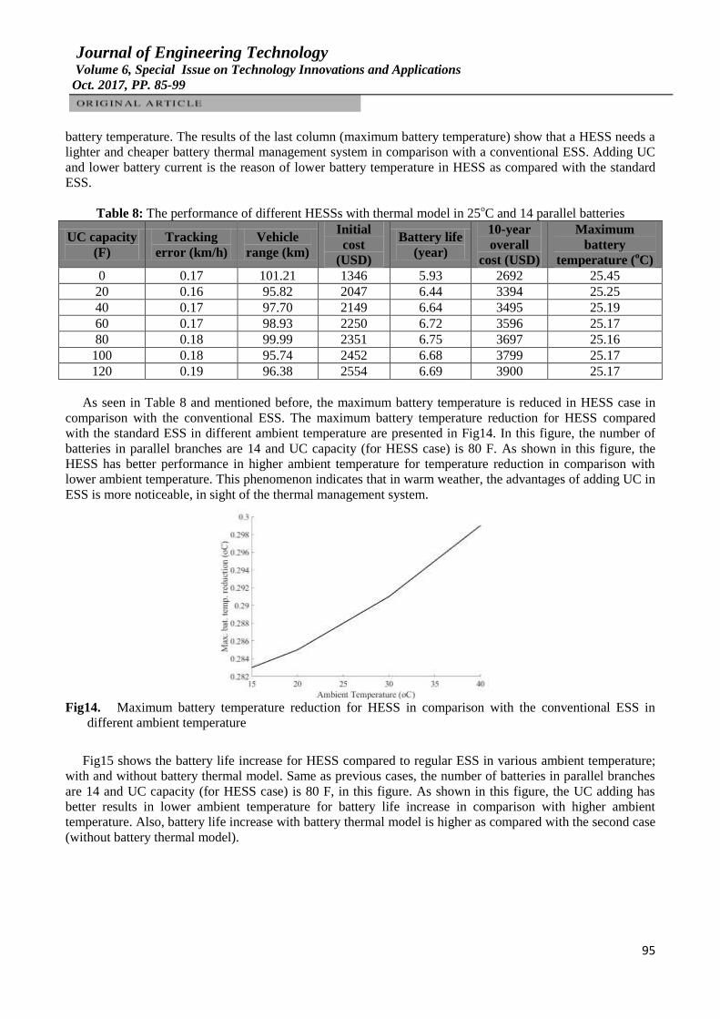
battery temperature. The results of the last column (maximum battery temperature) show that a HESS needs a
lighter and cheaper battery thermal management system in comparison with a conventional ESS. Adding UC
and lower battery current is the reason of lower battery temperature in HESS as compared with the standard
ESS.
Table 8: The performance of different HESSs with thermal model in 25oC and 14 parallel batteries
UC capacity
(F)
Tracking
error (km/h)
Vehicle
range (km)
Initial
cost
(USD)
Battery life
(year)
10-year
overall
cost (USD)
Maximum
battery
temperature (oC)
0 0.17 101.21 1346 5.93 2692 25.45
20 0.16 95.82 2047 6.44 3394 25.25
40 0.17 97.70 2149 6.64 3495 25.19
60 0.17 98.93 2250 6.72 3596 25.17
80 0.18 99.99 2351 6.75 3697 25.16
100 0.18 95.74 2452 6.68 3799 25.17
120 0.19 96.38 2554 6.69 3900 25.17
As seen in Table 8 and mentioned before, the maximum battery temperature is reduced in HESS case in
comparison with the conventional ESS. The maximum battery temperature reduction for HESS compared
with the standard ESS in different ambient temperature are presented in Fig14. In this figure, the number of
batteries in parallel branches are 14 and UC capacity (for HESS case) is 80 F. As shown in this figure, the
HESS has better performance in higher ambient temperature for temperature reduction in comparison with
lower ambient temperature. This phenomenon indicates that in warm weather, the advantages of adding UC in
ESS is more noticeable, in sight of the thermal management system.
Fig14. Maximum battery temperature reduction for HESS in comparison with the conventional ESS in
different ambient temperature
Fig15 shows the battery life increase for HESS compared to regular ESS in various ambient temperature;
with and without battery thermal model. Same as previous cases, the number of batteries in parallel branches
are 14 and UC capacity (for HESS case) is 80 F, in this figure. As shown in this figure, the UC adding has
better results in lower ambient temperature for battery life increase in comparison with higher ambient
temperature. Also, battery life increase with battery thermal model is higher as compared with the second case
(without battery thermal model).

Journal of Engineering Technology Volume 6, Special Issue on Technology Innovations and Applications Oct. 2017, PP. 85-99
96
Fig15. Battery life increase for HESS in comparison with the conventional ESS in different ambient
temperature; with and without battery thermal model
Fig16 shows the Battery SoC for HESS with and without battery thermal model. As seen in this figure, in
thermal modeling case (more actual case) the battery SoC is lower than of the battery model without a thermal
model. Therefore the effect of the thermal model should be considered for electric vehicle range calculation.
Fig16. Battery SoC for HESS with and without battery thermal model
6. Conclusion
The thermal modeling of the lithium battery is considered in this paper for studying its effect on battery
and hybrid battery/ultra-capacitor sizing process for an electric vehicle. As a case study, an electric
motorcycle is investigated in this research work.
The results of the conventional Energy Storage System (ESS) (battery) show that without battery thermal
modeling, 13 parallel batteries are suitable for the electric motorcycle. On the other hand, with battery thermal
modeling, at least 14 parallel batteries are needed to satisfy the vehicle range criterion (about 100 km) in 25oC
ambient temperature. Some other outcomes, in this case, are listed below:
Battery life is decreased when the ambient temperature growth.
Battery temperature rise is increased when the ambient temperature growth.
Vehicle range is increased when the ambient temperature growth.
In the Hybrid Energy Storage System (HESS) (battery/ultracapacitor) case, 80 F UC is a good sizing
solution in both with and without battery thermal model. Some conclusions, in this instance, are listed below:
As seen with battery thermal model, in HESS the maximum battery temperature is lower than a
conventional ESS. Therefore, a lighter and cheaper cooling system can be used in HESS in comparison
with the ESS.
Battery life improvement for a HESS is more noticeable when the battery thermal model is used as
compared with the case that the battery thermal model is disabled.
Journal of Engineering Technology Volume 6, Special Issue on Technology Innovations and Applications Oct. 2017, PP. 85-99
97
Acknowledgement
This work was support by Automotive Engineering Research Center (AERC) of Iran University of Science
and Technology (IUST).
References
[1] R. Saneifard, R. Dana, and A. Sianati, "Design and implementation of an electromechanical system
utilizing speed bumps to generate electric power," Journal of Engineering Technology, vol. 26, no. 2, pp. 16-
23, 2009.
[2] A. Safaei, M. R. Ha’iri-Yazdi, V. Esfahanian, M. Esfahanian, M. Masih-Tehrani and H. Nehzati,
"Designing an intelligent control strategy for hybrid powertrains utilizing a fuzzy driving cycle identification
agent," Proceedings of the Institution of Mechanical Engineers, Part D: Journal of Automobile Engineering,
vol. 229, no. 9, pp. 1169-1188, 2015.
[3] P. Ahmadizadeh and B. Mashadi, "Power flow and efficiency analysis of the EM power split
mechanism," Journal of the Brazilian Society of Mechanical Sciences and Engineering, vol. 39, no. 6, pp.
1947-1955, 2017.
[4] A. Mahmoudzadeh Andwari, A. Pesiridis, S. Rajoo, R. Martinez-Botas and V. Esfahanian, "A review of
Battery Electric Vehicle technology and readiness levels," Renewable and Sustainable Energy Reviews, vol.
78, pp. 414-430, 2017.
[5] A. Sharma and V. Strezov, "Life cycle environmental and economic impact assessment of alternative
transport fuels and power-train technologies," Energy, vol. 133, pp. 1132-1141, 2017.
[6] Y. Gao, J. Jiang, C. Zhang, W. Zhang, Z. Ma and Y. Jiang, "Lithium-ion battery aging mechanisms and
life model under different charging stresses," Journal of Power Sources, vol. 356, pp. 103-114, 2017.
[7] T. Xian, C. Soon, S. Rajoo and A. Romagnoli, "A parametric study: The impact of components sizing
on range extended electric vehicle's driving range," in 2016 Asian Conference on Energy, Power and
Transportation Electrification (ACEPT 2016), Singapore, Singapore, 2017.
[8] T. Markel, A. Brooker, T. Hendricks, V. Johnson, K. Kelly, B. Kramer, M. O'Keefe, S. Sprik and K.
Wipke, "ADVISOR: A systems analysis tool for advanced vehicle modeling," Journal of Power Sources, vol.
110, no. 1, pp. 255-266, 2002.
[9] F. Sangtarash, V. Esfahanian, H. Nehzati, S. Haddadi, M. Bavanpour and B. Haghpanah, "Effect of
different regenerative braking strategies on braking performance and fuel economy in a hybrid electric bus
employing cruise vehicle simulation," SAE International Journal of Fuels and Lubricants, vol. 1, no. 1, pp.
828-837, 2009.
[10] M. Esfahanian, A. Safaei, H. Nehzati, V. Esfahanian and M. Masih-Tehrani, "Matlab-based modeling,
simulation and design package for Eletric, Hydraulic and Flywheel hybrid powertrains of a city bus,"
International Journal of Automotive Technology, vol. 15, no. 6, pp. 1001-1013, 2014.
[11] H. He, R. Xiong and J. Fan, "Evaluation of lithium-ion battery equivalent circuit models for state of
charge estimation by an experimental approach," Energies, vol. 4, no. 4, pp. 582-598, 2011.
[12] O. Tremblay and L. Dessaint, "Experimental validation of a battery dynamic model for EV
applications," World Electric Vehicle Journal, vol. 3, no. 1, pp. 1-10, 2009.
[13] K. Smith and C.-Y. Wang, "Power and thermal characterization of a lithium-ion battery pack for
hybrid-electric vehicles," Journal of Power Sources, vol. 160, no. 1, pp. 662-673, 2006.
[14] K. Marr, V. Somandepalli and Q. Horn, "Explosion hazards due to failures of lithium-ion batteries," in
2013 AIChE Spring Meeting and 9th Global Congress on Process Safety (AIChE 2013), San Antonio (USA),
2013.
[15] S. Janarthanam, N. Burrows and B. Boddakayala, "Factors Influencing Liquid over Air Cooling of High
Voltage Battery Packs in an Electrified Vehicle," in SAE World Congress Experience (WCX 2017), Detroit
(USA), 2017.
[16] C. Arapatsakos, K. Galanopoulos and T. Koutroumanidis, "Catalyst temperature difference in relation
to carbon monoxide emissions in a four-stroke engine," Journal of Engineering Technology, vol. 21, no. 2, pp.
52-55, 2004.
Journal of Engineering Technology Volume 6, Special Issue on Technology Innovations and Applications Oct. 2017, PP. 85-99
98
[17] P. Nelson, R. Vijayagopal, K. Gallagher and A. Rousseau, "Sizing the battery power for PHEVs based
on battery efficiency, cost and operational cost savings," World Electric Vehicle Journal, vol. 6, no. 3, pp.
514-522, 2013.
[18] P. Correa, D. Fernandez, M. Gaudiano, L. Mathe, E. Moschen and P. Munoz, "Sizing and optimal
energy management in an electric vehicle with fuel cell using dynamic vehicle models," in 2nd IEEE Biennial
Congress of Argentina (ARGENCON 2014), San Carlos de Bariloche (Argentina), 2014.
[19] F. Colzi, M. De Nigris, A. Corti and S. Savaresi, "Extended range electric vehicles components
preliminary sizing based on real mission profiles," in 27th World Electric Vehicle Symposium and Exhibition
(EVS 2014), Barcelona (Spain), 2013.
[20] L. Malesani, L. Rossetto and P. Tenti, "Active power filter with hybrid energy storage," in 20th Annual
IEEE Power Electronics Specialists Conference (PESC'89), Milwaukee, WI, USA, 1989.
[21] X. Wu, X. Hu, Y. Teng, S. Qian and R. Cheng, "Optimal integration of a hybrid solar-battery power
source into smart home nanogrid with plug-in electric vehicle," Journal of Power Sources, vol. 363, no. 30
September 2017, pp. 277-283, 2017.
[22] M. Ruiz-Cortes, E. Romero-Cadaval, C. Roncero-Clemente, F. Barrero-Gonzalez and E. Gonzalez-
Romera, "Energy management strategy to coordinate batteries and ultracapacitors of a hybrid energy storage
system in a residential prosumer installation," in 2017 International Young Engineers Forum (YEF-ECE
2017), Tryp Lisboa Caparica Mar HotelCaparica (Portugal), 2017.
[23] R. Bartholomäus, T. Lehmann and U. Schneider, "Model predictive control of highly efficient dual
mode energy storage systems including DC/DC converter," in SpringerBriefs in Applied Sciences and
Technology, Berlin (Germany), Springer Verlag, 2018, pp. 33-46.
[24] S. M. Lukic, J. Cao, R. C. Bansal, F. Rodriguez and A. Emadi, "Energy storage systems for automotive
applications," IEEE Transactions on industrial electronics, vol. 55, no. 6, pp. 2258-2267, 2008.
[25] M. Masih-Tehrani, M.-R. Ha’iri-Yazdi, V. Esfahanian and H. Sagha, "Development of a hybrid energy
storage sizing algorithm associated with the evaluation of power management in different driving cycles,"
Journal of Mechanical Science and Technology, vol. 26, no. 12, pp. 4149-4159, 2012.
[26] Mathworks, "Implement generic battery model," 2017. [Online]. Available:
https://www.mathworks.com/help/physmod/sps/powersys/ref/battery.html.
[27] L. S. K. Saw, Y. Ye and A. Tay, "Electro-thermal analysis of Lithium Iron Phosphate battery for
electric vehicles," Journal of Power Sources, vol. 249, pp. 231-238, 2014.
[28] N. Omar, M. Monem, Y. Firouz, J. Salminen, J. Smekens, O. Hegazy, H. Gaulous, G. Mulder, P. Van
den Bossche, T. Coosemans and J. Van Mierlo, "Lithium iron phosphate based battery — Assessment of the
aging parameters and development of cycle life model," Applied Energy, vol. 113, no. January 2014, p. 1575–
1585, 2014.
[29] J. Wang, P. Liu, J. Hicks-Garner, E. Sherman, S. Soukiazian, M. Verbrugge and P. Finamore, "Cycle-
life model for graphite-LiFePO 4 cells," Journal of Power Sources, vol. 196, no. 8, pp. 3942-3948, 2011.
[30] M. Masih-Tehrani, M. R. Ha'iri-Yazdi, V. Esfahanian and A. Safaei, "Optimum sizing and optimum
energy management of a hybrid energy storage system for lithium battery life improvement," Journal of
Power Sources, vol. 244, pp. 2-10, 2013.
[31] M. Montazeri-Gh and M. Naghizadeh, "Development of car drive cycle for simulation of emissions and
fuel economy," in Proceedings of 15th European simulation symposium, Delft, The Netherlands, 2003.
[32] N. Xu and J. Riley, "Nonlinear analysis of a classical system: The double‐ layer capacitor,"
Electrochemistry Communications, vol. 13, no. 10, pp. 1077-1081, 2011.
[33] Mathworks, "Implement generic supercapacitor model," 2017. [Online]. Available:
https://www.mathworks.com/help/physmod/powersys/ref/supercapacitor.html.
[34] K. B. Oldham, "A Gouy–Chapman–Stern model of the double layer at a (metal)/(ionic liquid)
interface," Journal of Electroanalytical Chemistry, vol. 613, no. 2, pp. 131-138, 2008.
[35] E. Chemali, M. Preindl, P. Malysz and A. Emadi, "Electrochemical and electrostatic energy storage and
management systems for electric drive vehicles: State-of-the-art review and future trends."," IEEE Journal of
Emerging and Selected Topics in Power Electronics, vol. 4, no. 3, pp. 1117-1134, 2016.

Journal of Engineering Technology Volume 6, Special Issue on Technology Innovations and Applications Oct. 2017, PP. 85-99
99
[36] Z. Amjadi and S. S. Williamson, "Power-electronics-based solutions for plug-in hybrid electric vehicle
energy storage and management systems," IEEE Transactions on Industrial Electronics, vol. 57, no. 2, pp.
608-616, 2010.
[37] M. Masih-Tehrani, M. Hairi-Yazdi and V. Esfahanian, "Power Distribution Development and
Optimization of Hybrid Energy Storage System," International Journal of Automotive Engineering, vol. 4, no.
2, pp. 675-684, 2014.
[38] C. Zhu, X. Li, L. Song and L. Xiang, "Development of a theoretically based thermal model for lithium
ion battery pack," Journal of Power Sources, vol. 223, p. 155–164, 2013.
[39] O. Tremblay and L.-A. Dessaint, "Experimental validation of a battery dynamic model for EV
applications," World Electric Vehicle Journal, vol. 3, no. 1, 2009.