Study of inter-cell interference and its impact on the ...832429/FULLTEXT01.pdf · iii ABSTRACT...
105
Master Thesis Electrical Engineering September 2013 School of Computing Blekinge Institute of Technology 371 79 Karlskrona Sweden Study of inter-cell interference and its impact on the quality of video conference traffic in LTE Network MD. Jhirul Islam Mohammed Nazmul Haider Chowdhury
Transcript of Study of inter-cell interference and its impact on the ...832429/FULLTEXT01.pdf · iii ABSTRACT...

Master Thesis Electrical Engineering September 2013
School of Computing Blekinge Institute of Technology 371 79 Karlskrona Sweden
Study of inter-cell interference and its impact on the quality of
video conference traffic in LTE Network
MD. Jhirul Islam
Mohammed Nazmul Haider Chowdhury

ii
This thesis is submitted to the School of Computing at Blekinge Institute of Technology in partial fulfillment of the requirements for the degree of Master of Science in Electrical Engineering. The thesis is equivalent to 20 weeks of full time studies.
Contact Information: Author (1):
Md. Jhirul Islam Address: Fogdevagen 6, LGH 1004, 37140 Karlskrona, Sweden Email: [email protected] Author (2):
Mohammed Nazmul Haider Chowdhury Address: Fogdevagen 6, LGH 1004, 37140 Karlskrona, Sweden Email: [email protected]
Advisor:
Professor Adrian Popescu Blekinge Institute of Technology School of Computing SE-371 79 Karlskrona, Sweden Email: [email protected]
Examiner:
Dr. Patrik Arlos Blekinge Institute of Technology School of Computing SE-371 79 Karlskrona, Sweden Email: [email protected]
Internet : www.bth.se/com Phone : +46 455 38 50 00 Fax : +46 455 38 50 57
School of Computing Blekinge Institute of Technology 371 79 Karlskrona Sweden

iii
ABSTRACT
While inter-cell interference coordination (ICIC) for the downlink and uplink
of multi-cell systems (in general) and orthogonal frequency division multiple
access (OFDMA) networks (in particular) have been extensively studied, the study
of the impact caused by inter-cell interference with video conferencing traffic has
received less attention.
The consideration of video conferencing traffic is essential for analyzing
the overall performance analysis of inter-cell interference in LTE networks, and in
particular for the evaluation of the video conferencing traffic. In LTE networks, the
same frequencies can be used in several adjacent cells. This means that in
practice every cell may have other cell nearby whose radio transmissions may
interfere with the own signal.
In this paper, we report a comprehensive analysis on the performance of
video traffic considering the inter-cell interference impact in LTE network. The
interference patterns are configured by using the OPNET simulator for a given
set of parameters, such as cell configuration, user configurations, and traffic
models. The interference pattern is used to study the performance of video
conferencing traffic in LTE network for realistic deployments. We, present a
detailed description of the way to model the network in OPNET platform
considering the inter-cell interference. In order to use the suggested network
model in OPNET platform three network scenarios are configured. They are fully
overlapped, half overlapped and no frequency overlapping. These scenarios are
configured in such a way to show how the video traffic is impacted when the
network load increases.
The thesis shows that the video conferencing traffic experiences more delay
and loss when fully overlapped frequency is used in the adjacent cell on LTE
network.
Keywords: LTE, Inter-cell Interference, Video Conferencing, OPNET.

iv
ACKNOWLEDGEMENTS
This thesis was carried out at the Department of School of Computing under
the programme, Masters of Science in Electrical Engineering, Blekinge Institute of
Technology, Karlskrona, Sweden, under the supervision of Prof. Adrian Popescu.
First of all we would like to express our sincere gratitude to almighty ALLAH
for providing us with the determination, patience and strength to overcome all the
challenges and difficulties in the course of this dissertation and leading us to
successful completion.
We would like to thank our honorable supervisor Prof. Adrian Popescu and
Dr. Patrick Arlos who guided us throughout the thesis and gave us valuable
suggestions and advices and as well as for being a constant source of inspiration.
This project would have not been possible without their consistent advice and
encouragement.
Finally, we also would like to thank our parents, friends and well-wishers who
encouraged us always through their valuable advices, comments, and suggestions.
MD. Jhirul Islam
Mohammed Nazmul Haider Chowdhury
September 2013

v
CONTENTS
Abstract ............................................................................................................................................ III
Acknowledgements ..................................................................................................................... IV
Contents............................................................................................................................................. V
List of Tables ................................................................................................................................ VII
List of Figures .............................................................................................................................. VIII
List of Acronyms ........................................................................................................................... IX
1 Chapter One Introduction ...................................................................................................... 1
1.1 OVERVIEW ......................................................................................................................... 1
1.2 AIMS AND OBJECTIVES ...................................................................................................... 2
1.3 RESEARCH QUESTIONS ...................................................................................................... 2
1.4 RESEARCH METHODOLOGY ............................................................................................... 2
1.5 MOTIVATION AND CONTRIBUTION .................................................................................... 3
1.6 RELATED WORK ................................................................................................................ 3
1.7 THESIS OUTLINE ................................................................................................................ 4
2 Chapter Two Literature Studies ........................................................................................... 5
2.1 LTE BACKGROUND............................................................................................................ 5
2.1.1 Objectives of LTE and LTE-Advanced .......................................................... 5
2.2 LTE AND LTE-A RELEASES TIME AND FEATURES .............................................................. 6
2.3 SOME IMPORTANT FEATURES ............................................................................................. 6
2.3.1 Flexibility of Spectrum .................................................................................... 6
2.3.2 Multi-Antenna Method .................................................................................... 6
2.3.3 Power Control ................................................................................................... 7
2.3.4 Downlink Power Control ................................................................................ 7
2.3.5 Uplink Power Control ...................................................................................... 7
2.4 QUALITY OF SERVICE (QOS) .............................................................................................. 7
2.5 ARCHITECTURE OF LTE ..................................................................................................... 8
2.5.1 Central Part of Network .................................................................................. 9
2.5.2 Entrance Network ............................................................................................. 9
2.6 PROTOCOL STRUCTURAL DESIGN .................................................................................... 10
2.6.1 Non Access Stratum Layer ........................................................................... 10
2.6.2 Radio Resource Control Layer ..................................................................... 10
2.6.3 Radio Link Control Layer .............................................................................. 11
2.6.4 Packet Data Convergence Protocol Layer .................................................. 11
2.7 PHYSICAL LAYER ............................................................................................................. 11
2.7.1 Physical Layer Frame Formation ................................................................. 11
2.7.1.1 Uplink Frame Formation ................................................................. 12
2.7.1.2 Downlink Frame Formation ............................................................ 12
2.8 RESOURCE SLAB .............................................................................................................. 12
2.9 LOGICAL CONTROL ......................................................................................................... 13
2.10 TRANSPORT CONTROL .................................................................................................... 14
2.11 SC-FDMA UPLINK DIFFUSION ........................................................................................ 15
2.11.1 SC-FDMA Spreader ......................................................................................... 16
2.11.2 SC-FDMA Recipient ........................................................................................ 16
2.12 OFDM DOWNLINK DIFFUSION ........................................................................................ 16
2.12.1 OFDM Receiver ................................................................................................ 16

vi
2.13 MOBILITY MANAGEMENT ENTITY (MME) ........................................................................ 16
2.14 INTERFERENCE IN LTE ..................................................................................................... 17
3 Chapter Three Network Model and Implementation ................................................. 18
3.1 NETWORK MODEL CONFIGURATION ................................................................................ 18
3.1.1 Evolution Platforms ....................................................................................... 18
3.1.2 Why OPNET? .................................................................................................... 18
3.2 NETWORK MODEL CONFIGURATION ................................................................................ 18
3.2.1 Baseline Scenario ............................................................................................ 19
3.2.1.1 Baseline Scenario Description ........................................................ 19
3.2.1.1.1 Network Components ..................................................... 20
3.2.1.1.2 LTE Configuration ........................................................... 21
3.2.1.1.3 Interference Configuration ............................................ 22
3.2.1.1.4 Traffic Generation ........................................................... 23
3.2.1.1.5 Video Conferencing Pair Configuration ...................... 25
3.2.1.1.6 Mobility Configuration Using Trajectory Settings .... 26
3.2.2 Network Modeling and Configuration All Nine Scenarios ................ 29
3.2.2.1 Scenario1_FDD10mhz_Lowload_Fullyoverlapped ..................... 29
3.2.2.2 Scenario2_FDD10mhz_Lowload_Halfoverlapped ...................... 31
3.2.2.3 Scenario3_FDD10mhz_Lowload_Nooverlapped ......................... 31
3.2.2.4 Scenario4_FDD10mhz_Mediumload_Fullyoverlapped ............. 32
3.2.2.5 Scenario5_FDD10mhz_Medium Load_Halfoverlapped ............ 33
3.2.2.6 Scenario6_FDD10mhz_Medium Load_No Overlapped ............. 33
3.2.2.7 Scenario7_FDD10mhz_High Load_Fullyoverlapped ................. 33
3.2.2.8 Scenario8_FDD10mhz_Highload_Halfoverlapped ..................... 34
3.2.2.9 Scenario9_FDD10mhz_Highload_Nooverlapped ....................... 34
3.3 SIMULATION RUN ............................................................................................................ 34
3.4 COLLECTING STATISTICS ................................................................................................. 35
4 Chapter Four Results Analysis and Evaluation ........................................................... 36
4.1 PERFORMANCE OF LTE PHY UPLINK SNR (DB) ................................................................ 36
4.1.1 LTE Phy Uplink SNR (db) For Low-Load Network-1,2,3 .......................... 36
4.1.2 LTE Phy Uplink SNR (db) For Mid-Load Network-4,5,6 ........................... 37
4.1.3 LTE Phy Uplink SNR (db) For High-Load Network-7,8,9 ......................... 39
4.2 PERFORMANCE OF LTE HARQ UL RETRANSMISSION RATE ............................................ 40
4.2.1 LTE HARQ UL Retransmission Rate For Low-Load Network-1,2,3 ....... 40
4.2.2 LTE HARQ UL Retransmission Rate For Mid-Load Network-4,5,6 ....... 41
4.2.3 LTE HARQ UL Retransmission Rate For High-Load Network-7,8,9 ..... 42
4.3 PACKET END-TO-END DELAY AND VIDEO CONFERENCE TRAFFIC SENT/RECEIVED .......... 44
4.3.1 Packet E2E Delay and Video Packet for Low-Load Network-1,2,3 ....... 44
4.3.1.1 Video Traffic Packet Sent/Received .............................................. 45
4.3.1.2 Performance of Packet End-to-End (E2E) Delay .......................... 45
4.3.2 Packet E2E Delay and Video Packet for Mid-Load Network-4,5,6 ........ 46
4.3.3 Packet E2E Delay and Video Packet for High-Load Network-7,8,9 ...... 47
5 Chapter Five Conclusion and Future Work ................................................................... 49
5.1 ANSWER TO THE RESEARCH QUESTIONS ......................................................................... 49
5.2 FUTURE WORK ................................................................................................................ 50
Bibliography ................................................................................................................................... 51
Appendix ......................................................................................................................................... 55

vii
LIST OF TABLES
Table 2.1:Technical specifications published by the 3GPP group . ................................ 5
Table 2.2: Performance targets for LTE, Advanced-LTE . .................................................. 6
Table 3.1: Used components in the network ..................................................................... 20
Table 3.2: LTE Configuration Parameters ........................................................................... 21
Table 3.3: LTE FDD Profiles ................................................................................................... 21
Table 3.4: Summary of Interference Configuration ......................................................... 22
Table 3.5: Video Traffic Configuration Parameters (Application Attributes) ............. 23
Table 3.6: Profile Definition .................................................................................................. 24
Table 3.7: Network Configuration ........................................................................................ 25
Table 3.8: LTE Trajectory ....................................................................................................... 28
Table 3.9: Fully overlapped configuration parameters ................................................... 29
Table 3.10: Low Network Load Configuration. .................................................................. 30
Table 3.11: Half overlapped configuration parameters .................................................. 31
Table 3.12: 0% (No Interference) overlapped configuration parameters ..................... 32
Table 3.13: Medium network load parameters. ................................................................. 32
Table 3.14: Detailnetwork load configuration parameters. ............................................ 33
Table A.1: LTE PHY Uplink SNR (dB) for Scenarios (1, 2 and 3) ..................................... 55
Table A.2: LTE PHY Uplink SNR (dB) for Scenarios (4, 5 and 6) ..................................... 57
Table A.3: LTE PHY Uplink SNR (dB) for Scenarios (7, 8 and 9) ..................................... 59
Table A.4: HARQ.UL Retransmission Rate (packets/sec) for Scenarios (1, 2, 3) ........ 61
Table A.5: HARQ.UL Retransmission Rate (packets/sec) for Scenarios (4, 5, 6) ........ 64
Table A.6: HARQ.UL Retransmission Rate (packets/sec) for Scenarios (7, 8, 9) ........ 68
Table A.7: Packet End-to-End Delay (sec) for Scenarios (1, 2, 3) ................................... 72
Table A.8: Packet End-to-End Delay (sec) for Scenarios (4, 5, 6) ................................... 76
Table A.9: Packet End-to-End Delay (sec) for Scenarios (7, 8, 9) ................................... 80
Table A.10: Packet Received (bytes/sec) for Scenarios (1, 2, 3) ..................................... 84
Table A.11: Packet Received (bytes/sec) for Scenarios (4, 5, 6) ..................................... 88
Table A.12: Packet Received (bytes/sec) for Scenarios (7, 8, 9) ..................................... 92
viii
LIST OF FIGURES
Figure 1: Multi-layer transmission ......................................................................................... 7
Figure 2: High level architecture for 3GPP LTE . ................................................................. 8
Figure 3: Architecture of EPS (LTE/SAE) . ............................................................................. 8
Figure 4: Network Architecture ............................................................................................. 9
Figure 5: E-UTRAN Architecture . ........................................................................................... 9
Figure 6: Control plane protocols stack . ........................................................................... 10
Figure 7: User plane protocol stack . ................................................................................... 10
Figure 8: Frame structure . .................................................................................................... 11
Figure 9: Frame formation . ................................................................................................... 12
Figure 10: Resource slab of physical layer . ....................................................................... 12
Figure 11: Logical Channel in LTE . ...................................................................................... 13
Figure 12: Logical channel mapping . .................................................................................. 13
Figure 13: Transport channel in LTE . ................................................................................. 14
Figure 14: Transport control mapping . ............................................................................. 14
Figure 15: SC-FDMA Transmission . .................................................................................... 15
Figure 16: Mobility states of the UE in LTE . ...................................................................... 17
Figure 17: Methods for interference coordination in LTE networks. ........................... 17
Figure 18: Baseline Network Model Topology (Scenarios 1 to 9) .................................. 19
Figure 19: Mobility and Application deployment (Referred to Scenarios 1 to 9) ...... 25
Figure 20: Variable-Interval Trajectory File Format ......................................................... 26
Figure 21: Define Trajectory Dialog Box ............................................................................. 27
Figure 22: Trajectory Settings ............................................................................................... 28
Figure 23: Scenario_1_FDD10MHzFullyOverlapped ......................................................... 30
Figure 24: Scenario1_ FDD10MHz_LowLoad_FullyOverLapped ..................................... 30
Figure 25: Scenario_2_FDD10MHz_Low Load_Half Overlapped .................................... 31
Figure 26: Scenario_3_FDD10MHz_LowLoad_NoOverlapped ......................................... 32
Figure 27: Scenario4_FDD10MHz_MediumLoad_FullyOverlapped ............................... 33
Figure 28 : Scenario4_FDD10MHz_HighLoad_FullyOverlapped .................................... 34
Figure 29: LTE PHY Uplink SNR (dB) for Scenarios-1, 2, 3 .............................................. 36
Figure 30: LTE PHY Uplink SNR (dB) for Scenarios-4, 5, 6 .............................................. 38
Figure 31: LTE PHY Uplink SNR (dB) for Scenarios-7, 8, 9 .............................................. 39
Figure 32: LTE HARQ Rate (packets/Sec) for Scenarios-1, 2, 3 ...................................... 40
Figure 33: LTE HARQ UL Retransmission Rate (packets/Sec) for Scenarios-4,5,6 ..... 42
Figure 34: LTE HARQ UL Retransmission Rate (packets/Sec) for Scenarios-7,8,9 ..... 43
Figure 35: (a) Packet End-to-End Delay Packet Received and (b) Video Conference
Packet Sent for Scenarios-1, 2, 3 .................................................................................. 44
Figure 36: (a) Packet End-to-End Delay Packet Received and (b) Video Conference
Packet Sent for Scenarios-4, 5, and 6 .......................................................................... 46
Figure 37: (a) Packet End-to-End Delay Packet Received (b) Video ConfeSecce Packet
Sent (bytes/sec) for Scenarios-7, 8, 9 .......................................................................... 47

ix
LIST OF ACRONYMS
3GPP Third Generation Partnership Project
ARP Allocation and Retention Priority
AMBR Aggregate MBR
CDMA Code Division Multiple Access
DwPTS Downlink Pilot Timeslot
DES Discrete Event System
DFT Discrete Fourier Transform
EPS Evolved Packet System
eNB/eNodeB Evolved Node B
EPC Evolved Packet Core
E2E Delay End- to-End Delay
E-UTRAN Evolved Universal Teresstrial Radio Access network
FDMA Frequency Division Multiple Access
FDD Frequency Division Duplex
GP Guard period
GERAN GSM Edge Radio Access Network
HSPA High Speed packet Access
IDFT Inverse Discrete Fourier Transform
ITU International Telecommunication Union
LTE Long Term Evolution
LTE-A Long Term Evolution-Advanced
MAC Medium Access Control
MIMO Multiple Input Multiple Output
MBR Maximum Bit Rate
MME Mobility Management Entity
Non GBR Non-Guaranteed Bit Rate
OPNET Optimized Network Engineering Tool
OFDMA Orthogonal Frequency Division Multiple Access
OFDM Orthogonal Frequency Division Multiplexing
PAPR Peak–to-Average power Ratio
PCRF Policy and Charging Rules Function
PDCP Packet Data Control Protocol
PCM Pulse Code Modulation
PDN-GW Packet Data Network Gateway
PSTN Public Switched Telephone Network

x
QoS Quality of Service
QCI QoS Class Identifier
RB Resource Block
RLC Radio Link Control
ROHC Robust Header Compression
RTP Real -Time Transport Protocol
RRC Radio Resource Control
RAN Radio Access Network
SM Spatial Multiplexing
S-GW Serving Gateway
SDFs Service Data Flows
SC-FDMA Single Carrier FDMA
TCP Transmission Control protocol
TDD Time Division Duplex
TDMA Time Division Multiple Access
UE User Terminal
UL Uplink
UDP User Datagram Protocol
UTRAN Universal Terrestrial Radio Access Network
UTRA Universal Terrestrial Radio Access
UPTS Uplink Pilot Timeslot
UMTS Universal Mobile Telecommunication Systems
VoIP Voice over Internet Protocol
WiMAX Worldwide Interoperability For Microwave Access

1
1 CHAPTER ONE INTRODUCTION
In this chapter, the overview of LTE, aims and objectives, research
methodology, contributions and related work for this thesis and its outline are
discussed.
1.1 Overview
Ever increasing multimedia services make telecom operator to use the
spectrum more aggressively. By doing aggressive utilization of the spectrum turns
out an enhancement of inter-cell interference (ICI) in the network which creates
traffic jam in telecommunication network infrastructure. Allocation of the same
frequency in neighboring cells deteriorates the performance of ICI. When this is
the case, network designers are required to analyze the behavior of ICI so that they
can better quantify the network performance for real-time applications such as
video conferencing traffic and proper resource optimization.
Orthogonal frequency division multiple access (OFDMA) has been recently adopted
as the multiple access scheme for the state-of-the-art LTE. The orthogonality among
the subcarriers per cell makes the intra-cell interference almost negligible.
However, with universal frequency reuse among cells (i.e., all cells use the same set
of subcarriers), the ICI at each subcarrier may cause severe degradation in the
network performance.
In OFDMA networks, the subcarriers are allocated adaptively among users per cell
based on a predefined scheduling scheme. Moreover, each subcarrier is allocated to
only one user per cell assuming BSs are equipped with a single antenna and, thus,
the number of interfering users on each subcarrier is rather limited [1]. In
comparison to downlink, the nature of uplink ICI is different in various aspects
that include: (i) Due to the implicit symmetry and fixed locations of the BSs in the
typical grid-based downlink network models, the number of significantly
contributing interferers typically remains the same irrespective of the position of
the mobile receiver. Also, it has been shown in [3] that the strongest interference is
generated by two closer interfering BSs irrespective of the mobile receiver location.
However, the number of significantly contributing interference the uplink cannot
be quantified at a given instant due to the highly varying locations of the
interfering mobile transmitters; (ii) Conditioned on the location of the desired
mobile receiver within a cell, the exact distance of the interfering BSs can be
calculated in the typical grid-based downlink network models. However, knowing
the location of the BS receiver in the uplink does not help in determining the exact
location of the interfering mobile users; (iii) In the uplink, cell edge and cell center
mobile users are subject to the same amount of interference on a given subcarrier,
which is the interference received at the BS whereas the same is not true for the
downlink in which cell edge users experience higher interference coming from the
nearby BSs [2] [4], [5], [6], [7]. Based on the above mentioned studies, there are
limited studies, in particular, on how ICI impacts on the performance video traffic.
Therefore, in this thesis paper, a comparative study has been done on the
performance evaluation of ICI impact on the video conference traffic.

2
1.2 Aims and Objectives
This thesis studies and analyzes the effects of inter-cell interference based
on how the frequency should be allocated to different LTE cells for the
particular purpose. The main goal is to determine the extent of the impact on
the quality of video traffic caused by the inter-cell interference, when the node is
moving around the adjacent cell. Other aims include providing appropriate
methodologies and guidelines that can be followed in future research:
Construct a LTE network in OPNET for performing video conferencing.
Develop, test and evaluate scenario-driven simulation in OPNET.
Employ preconfigured interference during the implementation of
the suggested network model in a LTE simulation environment.
Discuss different constraints that affect performance metrics (e.g., end-
to-end delay, packet loss, LTE HARQ uplink retransmission rate and
uplink SNR) and critically examine various approaches suggested in the
literature.
Analyze the simulation results of different network scenarios with
different network loads.
1.3 Research Questions
Question 1. What is the impact of inter-cell interference on the uplink SNR?
Question 2. What is the impact of the cell on the uplink retransmission
performance?
Question 3. What is the impact on the packet end-to-end delay and packet
loss for the video conferencing traffic under different network
loads?
1.4 Research Methodology
In order to assess the impact of inter-cell interference on video quality in
terms of packet end- to-end delay and packet loss in a LTE generating, after
thoughtful consideration, computer simulation has been considered for producing
and analyzing the data. In our case, the results of computer simulation can be
analyzed with regard to the performance of video conferencing in LTE network, to
represent a real system. As most practitioners and engineers advocate, this
methodology has been widely used as an effective method to tune, debug and
optimize the network infrastructures. With the wide variety of existing simulation
software, flexibility is highly influenced in the course of model development while
hardware cost is minimized. Another approach could be mathematical modeling of
the environment in a suitable programming language, but it has its own advantages
and disadvantages. Advantage is flexibility and precision but main disadvantage is
the reliability. Enormous knowledge and experience required to build the model

3
can be a limitation and validating the result through comparison with real network
data can be time consuming and costly. At the outset, the key factors influencing
video quality in terms of end- to-end delay and packet loss in a LTE environment
are identified by taking help from existing research and knowledge based on well-
known scholars, related articles and journals like IEEE Xplore, ACM, SCOPUS,
Inspec, Google and Google Scholar. Following this, a detailed survey of the existing
literature related to the current area of research is conducted. The required data
will be collected for the assessment. For the purpose of the present study, the
LTE network models are designed on the workspace of the OPNET simulator
with the help of different network entities. Multiple experiments are deployed with
different network loads to investigate the effect of inter-cell interference on the
video quality in terms of packet end-to-end delay and packet loss. The simulation
results are reported in different statistical plots and tables. Post-processing of the
data provide information about the impact of inter-cell interference on the uplink
SNR and the impact of the cell on the uplink retransmission performance.
1.5 Motivation and Contribution
Emergence of video traffic has been evident over the last years and LTE is
believed to deliver and satisfy the growing demands. In the LTE network, inter-cell
interference is one of the important fields of studies, which has not been explored
in a greater extent move. It is important to study how quality of video traffic is
impacted if UEs (User Equipment) moves towards the adjacent cell and if uplink
and downlink frequencies are overlapped (that causes inter-cell interference). Our
suggested approach has two fold contributions. First it allows to gain a better
understanding of the LTE network technologies along with the concepts of inter-
cell interference (ICI). Second, the proposed simulation based study enables us to
learn how an LTE network is deployed thereby resulting in a significant knowledge
gain in this particular field.
1.6 Related Work
In study [1], a novel framework for modeling the uplink inter-cell interference
(ICI) in a multiuser cellular network is presented. The proposed framework assists
in quantifying the impact of various fading channel models and state-of-the-art
scheduling schemes on the uplink ICI. Some worth mentioning research works for
the uplink appear in [6], [8], [9]. In paper [6], the authors developed an analytical
model for subcarrier collisions as a function of the cell load and frequency reuse
pattern. They derived an expression for the SINR in the uplink and downlink,
ignoring the effect of shadowing and fading. In another study [8], the authors
developed an analytical expression for the subcarrier collision probability
considering non-coordinated schedulers. In [10], the authors modeled uplink ICI in
an OFDMA network as a function of the reuse partitioning radius and traffic load
assuming arbitrary scheduling. Viering et al. [9], the authors presented a semi-
analytical method to approximate the distribution of the uplink ICI through
numerical simulations without considering the impact of scheduling schemes. As
we have not found any literature related work to ICI impact on video conferencing
traffic, we choose this topic as our thesis.

4
1.7 Thesis Outline
The outline of this thesis paper is organized as follows:
Chapter 1
In this chapter, the introduction, motivation and contribution, aims and objectives,
research methodology, and related work are discussed. It also discusses about the
research question and scope of this thesis paper.
Chapter 2
Discusses about the literature studies of Long Term Evolution (LTE), Different layer
architecture, Mobility Management and Inter-cell Interference (ICI).
Chapter 3
Discuss about the network modeling and simulation.
Chapter 4
This chapter is dedicated to illustrate the simulation results.
Chapter 5
Concludes the research works with possible future work.

5
2 CHAPTER TWO LITERATURE STUDIES
2.1 LTE Background
Long–Term Evolution (LTE) and Long-Term Evolution Advanced (LTE-A) [11],
[14] is a promising radio access network technology, standardized in 3GPP
[15]. LTE is a step, towards the 4G technology for mobile voice, video and data
networks that provides increased data rates and developed performance. The top
telecom operators have chosen LTE and LTE-A for their 4G network operation [15].
Future wireless networks will need to be optimized for the delivery of a range of
video contents and video-based applications [12]. The Evolved UMTS Terrestrial
Radio Access (E-UTRA) system of LTE uses orthogonal frequency-division multiple
access (OFDMA) for the downlink and Single-Carrier FDMA (SC-FDMA) for the
uplink [13]. In the LTE networks, QoS implies traffic differentiation and using
multiple bearers with configuration and priorities optimized to ensure satisfactory
service quality for each user.
2.1.1 Objectives of LTE and LTE-Advanced
The overall objective for LTE is to offer an extremely high performance radio
access technology which offers complete vehicular speed mobility and that can
readily coexist with HSPA and earlier networks. LTE is referred as Universal
Terrestrial Radio Access Network (E-UTRAN). LTE supports Downlink peak data
rates up to 326 Mbps with 20 MHz bandwidth and Uplink peak data rates up to
86.4 Mbps with 20 MHz bandwidth. LTE also supports scalable bandwidth such as
1.4 MHz, 3 MHz, 5 MHz, 10 MHz, 15 MHz, and 20 MHz .Besides, LTE supports
reduced latency up to 10 milliseconds (ms) round-trip times between user
equipment and the base station, and to less than 100 ms transition time from
inactive to active [16].
Table 2.1:Technical specifications published by the 3GPP group [17].
Release Specification Date Downlink Data Rate
Uplink Data Rate
Round Trip Time
Release 99 WCDMA March, 2000
384 kbps 128 kbps 150 ms
Release 4 TD-
SCDMA March, 2001
384 kbps 128 kbps 150 ms
Release 5 HSDPA March to
June, 2002 14 Mbps 5.7 Mbps <100ms
Release 6 HSUPA December,
2004 to March, 2005
14 Mbps 5.7 Mbps <100ms
Release 7 HSPA December,
2007 28 Mbps 11 Mbps <50 ms
Release 8 LTE December,
2008 100 Mbps 50 Mbps 10 ms
Release 10 LTE-
Advanced Published
2012 1 Gbps in
a low mobility 375 Mbps 5ms

6
2.2 LTE and LTE-A Releases Time and Features
In this section we discuss LTE release time and some important features. We
shown the previous page table 2.1 which is the technical specifications published
by the 3GPP group [17].
Table 2.2: Performance targets for LTE, Advanced-LTE [17].
Item Subcategory LTE (3.9G) Target [9]
LTEAdvanced (4G) target [10]
Peak spectral efficiency (b/s/Hz)
Downlink 16.3
(4x4 MIMO) 30 (up to 8x8
MIMO)
Uplink 4.32
(64QAM SISO) 15 (up to 4x4
MIMO)
Downlink cell Spectral efficiency (b/s/Hz), 3 m/h,
500m ISD
2x2 MIMO 1.69 2.4
4.2 MIMO 1.87 2.6
4x4 MIMO 2.67 3.7
Downlink cell Edge user spectral efficiency (b/s/Hz)
5percntile, 10 users, 500 m ISD
2x2 MIMO 0.05 0.07
4x2 MIMO 0.06 0.09
4x4 MIMO 0.08 0.12
2.3 Some Important Features
In this part we discuss some key features of LTE and LTE-Advanced which is
important to perform for the LTE.
2.3.1 Flexibility of Spectrum
Radio spectrum is offered for various frequency bands and sizes
for mobile communication that shows as both paired and unpaired bands. Paired
contains both uplink and downlink transmission which supports various frequency
bands. LTE´s bandwidth capacity is 1.4 MHz to 20 MHz. It also supports second
duplex in full and half duplex modes.
2.3.2 Multi-Antenna Method
One of the important parts of the LTE is Multi-antenna. LTE contains Multi-antenna
method by the transmit diversity and multi-flexing like as Multiple Input
Multiple Output (MIMO). Some antennas and beam constructing multiple antennas
method which is based on scenarios. Transmit diversity of LTE depends on Space
Frequency Block Schemes (SBFC) complemented along with Frequency Switched
Transmit Diversity (FSTD), which can be used to VOIP. Multiple antennas can apply
the transmitter and receiver, which need simultaneous transmission which are
depicted in the following figure. Some transmit antennas and receiver antennas
that can be transmitted up to four data streams parallel over the same radio link
[18].

7
Improved diversity performance Beam forming improved
Spatial-division multiple access improved Multi-layer transmission improved
Figure 1: Multi-layer transmission
2.3.3 Power Control
The power which is gathered through the control unit is essentially
increased while ensuring minimum interference in the process [18].
2.3.4 Downlink power control
Inter-cell coordination entails limitations of the transmission power in a few
parts of the transmission bandwidth in the downlink. The downlink
synchronization provides the comparative narrow band diffusion power indicator
where a cell can pass on the information to the neighboring cells. The neighboring
cells deploy to the overall dimension of the output of the spectrum. A crucial
element of the carried inter-cell-interference coordination system in LTE is that full-
frequency reuse in neighboring cells is possible [18].
2.3.5 Uplink Power Control
One of the techniques in LTE is Uplink Power Control which is used to control
for both the received signal strength in the intended cell and the amount of
interference in neighboring cells. Besides, Fractional path loose compensation is
provided by the Uplink Power Control for less interference [18].
2.4 Quality of Service (QoS)
It is necessary to continue the Quality of Service (QoS) for increasing multimedia
application over the internet, which can make sure the assured service through the

8
internet. Voice, video services needless delay for maintaining the Quality of service.
IETF (Internet Engineering Task Force) suggested various techniques, models and
policies for maintaining the QoS demand. Quality of Service Class Identifier (QCI)
can separate packets in classes depending on priority. Traffic Forwarding Policy
(TFP) is also connected with QCI which assign required bandwidth. QoS contains
MBR and GBR values, which may be set as required.
2.5 Architecture of LTE
Long Term Evolution (LTE) has been considered to maintain only packet-
switched service for providing seamless Internet Protocol (IP) connectivity between
the packet data network (PDN) and the user equipment (UE), without any
interruption to the end users‟ applications during the period of mobility.
The term “LTE” covers the advancement of the Universal Mobile
Telecommunications System (UMTS) radio access through the Evolved UTRAN (E-
UTRAN). LTE is accompanied through the non-radio aspects under the term
“System Architecture Evolution” (SAE), which includes the Evolved Packet Core
(EPC) network. SAE and LTE consist of the Evolved Packet System (EPS). The LTE and
SAE architecture decreases operating expenses (OPEX) and capital expenditures
(CAPEX).
Figure 2: High level architecture for 3GPP LTE [16].
Figure 3: Architecture of EPS (LTE/SAE) [21].

9
EPS is the combination of CN and E-UTRAN radio access network. Core Network
(CN) delivers access to external packet IP networks assures privacy, security, QoS,
and terminal context management.
Figure 4: Network Architecture [20].
2.5.1 Central part of network
The central network or core network is referred as Evolved Packet Core (EPC).
The significance of the EPC is to store operating node numbers at as minimum
levels as possible. Some core logical nodes are Serving Gateway (S-GW), Mobility
Management Entity (MME), PDN Gateway (P-GW), Policy and Charging Rules
Functions (PCRF), Home Subscriber Server (HSS) etc [21].
2.5.2 Entrance Network
Access network, E-UTRAN creates the eNodes that are linked by an interface
which is referred as “X2”, eNodes are linked with the “S1” interface to the EPC. S1-
MME and S1-U interfaces are responsible for connecting to the MME and S-GW
respectively. The E-UTRAN is accountable for all radio related functions like Radio
Resource Management (RRM), Header Compression, Security and Connectivity to
the EPC.
Figure 5: E-UTRAN Architecture [21].

10
2.6 Protocol Structural Design
In this section we present various protocol layers and their functions in LTE.
Figure 6: Control plane protocols stack [16].
Figure 7: User plane protocol stack [16].
2.6.1 Non Access Stratum Layer
The NAS executes between the User Equipment and Mobility Management
Entity (MME). It is used for authentication, mobility management bearers setting up
in respect to the control plane [16].
2.6.2 Radio Resource Control Layer
The RRC executes between the UE and eNodeB. It is linked to the control
plane. It is accountable for the radio bearer maintenance and setting up [16].

11
2.6.3 Radio Link Control Layer
The RLC layer is performed for the vehicle traffic configuration from UE to
eNodeB. Three different reliability modes that RLC delivers for data transport are –
Acknowledge Mode (AM), Unacknowledged Mode (UM) and Transparent Mode (TM)
[16].
2.6.4 Packet Data Convergence Protocol Layer
PDCP layer performs for both the user plane and control plane. It is
accountable in balancing both uplink and downlink [16].
2.7 Physical Layer
The physical layer is one of the important functions of LTE to relocate reliable
signal over a radio interface between UE and eNodeB. The air interface of LTE is
designed to use unpaired TDD and each paired FDD mode spectrum bands. It
delivers top layer move data service through the MAC sub layer. It is used for SC-
FDMA in support of UL and FDMA designed for DL, protecting multipath fading
and maintaining MIMO for top data rates. The physical layer activities are [22],
[23] EFC encoding and decoding of transport channel, Modulation and
Demodulation, time synchronization and frequency, RF processing, MIMO antenna
processing and Radio characteristics capability [23].
2.7.1 Physical Layer Frame Formation
Signals of the transmission are converted into a frame where 10 sub frames
are consisted of each frame. Each sub frame consists of 2 slots. Each slot contains
7 SC-FDMA symbols.
Figure 8: Frame structure [23].

12
2.7.1.1 Uplink Frame Formation
Uplink frame formation is same like as downlink frame. It contains 20 slots
and every sub- frame contains 2 slots. The time duration of every slot is 0.5ms [23].
2.7.1.2 Downlink Frame Formation
It contains various sub-carrier symbols for multi users where every user
selects sub-carrier with the time slot. In LTE, it is known as Physical Resource
Blocks and identified by the same factors likes eNodeB, frequency and time [24].
Figure 9: Frame formation [23].
2.8 Resource Slab
Resource slab is the time frequency component for downlink transmission in
LTE. It is represented as base station scheduler.
Figure 10: Resource slab of physical layer [28].

13
Standard CP (cyclic prefix) is used by the resource slab of the physical layer. One
slot of Resource slab contains 12 contagious sub-carriers. Each slot for time
duration is 0.5ms for 7 consecutive symbols. Each slot of resource slab contains 84
resource elements and 180 KHz in the time domain and frequency domain
respectively. Each Resource slab´s bandwidth is same. Eventually resource slab of
the physical layer is always dependent on the transmission bandwidth [23], [28].
2.9 Logical Control
Logical channel is the connection between the RLC and MAC over various
logical channels, which facilitates data transfer service and identifies various data
information that contains logical channel which includes both traffic channel and
control channel.
Figure 11: Logical Channel in LTE [16].
Figure 12: Logical channel mapping [16].

14
Paging Control Channel (PCCH): It is implemented when the network does
not know the location cell of the UE.
Broadcast Control Channel (BCCH): Down link channel is implemented in
broadcasting control information.
Common Control Channel (CCCH): It is performed for control sending
information the network and UE.
Dedicated Control Channel (DCCH): It is a bidirectional channel and used
for broadcasting control information between the network and UE.
Dedicated Traffic Channel (DTCH): It is a point to point channel that is
identified to one UE to transfer user information.
Multicast Control Channel (MCCH): Downlink point to point channel
which relay Multimedia Broadcast and Multicast Service (MBMS) control
information to the UE from the network.
Multicast Traffic Channel (MTCH): Downlink point to point channel which
relay traffic data from the network to the UE [26].
2.10 Transport Control
Transport control executes data transfer service and identifies the procedure
of the information is accepted for particular physical modulation which is
unchanged [34].
Figure 13: Transport channel in LTE [16].
Figure 14: Transport control mapping [16].

15
Multicast Channel (MCH): It is known as a downlink channel which
performs MBMS transmission on different cell and relay the whole area of
the cell.
Paging Channel (PCH): It is a downlink channel which relays the whole area
of the cell. It provides UE discontinuous reception for enabling UE power
saving.
Random Access Channel (RACH): It´s known as an uplink channel that
contains minimum information.
Downlink Shared Channel (DL-SCH): It is a downlink channel which
performs Hybrid ARQ and detects by the coding, transmitting power and
modulation.
Broadcast Channel (BCH): It is a pre-defined downlink channel which relays
the whole area of the cell.
UL-SCH (Up link shared channel): The channel which performs potential
variation and detects by coding, modulation and transmit power is known as
Uplink Shared Channel. It performs semi-static resource allocation [26].
2.11 SC-FDMA Uplink Diffusion
SC-FDMA (single carrier frequency division multiple access) is the latest
creation for achieving high data rates uplink diffusion rate which is recognized by
the 3GPP (3rd generation project partnership) for now and LTE which is
referred as a cellular system for the future generation. It contains 1.25-
20MHz bandwidth and up to 20 Mbps transmission rate. SC-FDMA which is
modified by the OFDM that in the outcome similar of throughput motion and
complexity. PAPR (Peak to Average Power Ratio) is the main benefit of the SC-FDMA
than the OFDMA that is inferior power consumption for uplink channel which
occurs longer battery lifetime of mobile stations and reduce manufacturing
cost [29], [30], [31].
Figure 15: SC-FDMA Transmission [29].

16
2.11.1 SC-FDMA Spreader
In SC-FDMA, QPSK, 16QAM transmits the signal. After using N point DFT
(Discrete Fourier Transform) QPSK input and separated into N- symbol wedges. It
switches to the frequency domain which is characterized by Xk of the input
symbol. Subcarriers result mapping creates the X l set (l =0, 1, 2…… M-1). Later X1
switched to a complex time domain signal Xm with M point Inverse DFT. Every Xm
symbols adding CP (Cyclic Prefix) to pass on frequently to avoid IBI (Inner Block
Interface) because of multipath propagation [29].
2.11.2 SC-FDMA Recipient
The receiver of SC-FDMA accepts the signal after converting it into the
frequency domain with DFT, after that de-maps the subscribers and later executes
the frequency domain equalization for avoiding ISI. Inter Symbol Interference (ISI)
may be happened in the particular carrier modulation with SC-FDMA, MMSE
(Minimum Mean Square Error) is chosen for practical consideration. Then
equalization symbols are converted back to time domain with IDFT. Symbols
decoding and detection happens in the time domain [29].
2.12 OFDM Downlink Diffusion
Initially OFDM spreader separates input high data streams into various low
rate data streams. The entire parallel streams are formed by a forwarding error
correction scheme which is IFFT input measure the time part relation to the
sub channel [33]. At last the transmission channel filters the time signal and
transfer into high frequency and transmission over the channel.
2.12.1 OFDM Receiver
The receiver of OFDM accepted initially the modified signal into various signals
that are stored by the reception filter. After removing the guard interval, the FFT is
changed into the samples from time into the frequency domain. The receiver,
complex symbols which are more decoded and mapped. Finally the data flow of the
unique serial is received [27].
2.13 Mobility Management Entity (MME)
The chief control-node of the LTE access network is Mobility Management Entity
(MME). Based on the radio technologies of the source, the mobility-state of the User
Equipment ( UE) and the target cells, MME can be classified. Mobility management is
liable for both the paging procedure and the idle mode UE tracking together with
retransmissions. The bearer activation/deactivation technique and the Serving
Gateway (SGW) for a UE at the preliminary attach and at time of intra-LTE handover
involving Core Network (CN) node relocation is linked with the mobility
management. Besides, Mobility management is accountable to authenticate the user
and verifies the authorization of the UE for camping on the service provider´s
public Land Mobile Network (PLMN) [16].

17
Figure 16: Mobility states of the UE in LTE [16].
2.14 Interference in LTE
The major issue in LTE network is Interference. Interference consists of data
transmitted in either the similar transmit mode as the valuable data from the
serving eNodeB, or using a different transmit mode. Intra cell- interference, Self-
noise interference, Inter cell-interference and Crossed timeslot interference are the
four categories of the Interferences. For the receiver design, interference
mitigation is required in LTE systems. The helpful implementation of interference
mitigation theory in LTE requires OFDMA architecture intimate knowledge [35].
Figure 17: Methods for interference coordination in LTE networks [36].

18
3 CHAPTER THREE NETWORK MODEL AND IMPLEMENTATION
3.1 Network Model Configuration
The following subsequent sections discuss about the network components
used in the network models and video traffic generation in OPNET.
3.1.1 Evolution Platforms
In a well-designed network model, accessing performance of different
parameters such as E2E delay, packet loss etc. is important. But in the practical
world, the performance evaluation of a network model is challenging. OPNET
Technologies [19] has introduced a tool named Optimized Network Engineering
Tool (OPNET), which is used to evaluate the performance of a network model.
OPNET is a proprietary simulation software based on Discrete Event System (DES)
and it is object oriented. It has comprehensive build-in features. In this thesis
paper, OPNET modeler 17.1 is used for designing and developing simulation
models. In the following section, it is discussed in details about OPNET modeler
and the reason why OPNET is chosen as a modeler.
3.1.2 Why OPNET?
Because of the following features OPNET modeler has been selected instead of
other different simulators:
For both the communication network and distributed systems, dynamic
development environment and support are provided.
Comprehensive documentation is offered to the users.
Intuitive graphical interface is offered that allows the user to work and
view the results easily.
OPNET provides flexible results with comprehensive tools to exhibit, plot
and scrutinize time series, histograms, probability, parametric curve and
confidential intervals.
It allows accessing the wide range of available standards and the venders
communication network which permit modelers to enhance models in
simulation. In addition, it lessens model development.
3.2 Network Model Configuration
This section explains the network model used in this study. Followed by the
baseline scenario outlined in section 1.1.1, nine network scenarios will be modeled,
which will be elaborately demonstrated in the up-coming sections. Scenarios one,
two and three are modeled to demonstrate the imposition of low network load and
experienced with 100%, 50% and 0% frequency interference, respectively. Scenarios
four, five and six experiencing medium network load is configured with 100%, 50%

19
and 0% frequency interference, correspondingly. Scenarios seven, eight and nine
are modeled to demonstrate the high network load. Scenarios seven, eight and nine
are configured with 100%, 50% and 0% frequency interference, in that order.
3.2.1 Baseline Scenario
The following scenario is modeled in a way that related configuration for all nine
scenarios can be replicated from the baseline scenario considering three different
network load and interferences.
3.2.1.1 Baseline Scenario Description
Baseline LTE network topology shown in Figure 18 consists of two eNodeBs, one
trajectory configured on UE_mobile representing its mobility, two UEs (User
Equipments, UE_mobile and UE_fix), one EPC (Evolved Packet Core), one IP_Cloud,
one router (Gateway) and two workstations (VConf_Destination_mobile and
VConf_Destination_fix). eNodeB_1 corresponds to one single cell while eNodeB_2
belongs to another cell. eNodeB_1 connects EPC (Evolved Core Packet) by using the
PPP_DS3 duplex link operated at the data rate of 44 Mbps. EPC, IP_Cloud and
Router ( gateway) are connected each other by using the PPP_ DS3 link operated at
the data rate of 44Mbps. Two destination workstations are connected to the router
(gateway) using 10BaseT Ethernet link. SONET/OC3 link operating at the rate of
148.61 Mbps is used to establish the connection between eNodeBs and EPC
(Evolved Packet Core). Application Configuration, Profile Configuration and LTE
Configuration objects have been used and illustrated in the following sections.
Figure 18: Baseline Network Model Topology (Scenarios 1 to 9)

20
The ip32_cloud node model represents an IP cloud supporting up to 32 serial line
interfaces at a selectable data rate. IP_Cloud is connected between EPC and gateway
using PPP_DS3 which is operating at the data rate of 44.736 Mbps. The router,
gateway, represents an IP-based gateway connecting two workstations
(VConf_Destination_mobile and VConf_Destination_fix) using a 10BaseT Ethernet
cable. The 100BaseT duplex link is used between gateway and both workstations
(VConf_Destination_Mobile and VConf_Destination_Fix). UE_fix operating as source
node is destined at VConf_Destination_fix node connected with a gateway while
UE_mode operating as source node is destined at VConf_Destination_mobile
connected with a gateway. In order to identify which UE belongs to which eNodeB,
ID for eNode_1 and eNodeB_2 is set at 1 and 2, receptively. In this network,
UE_mobile and UE_fix representing LTE user equipment have been considered as
source nodes for video conferencing traffic. UE_mobile communicates using
eNodeB_2 while UE_fix communicates through eNodeB_1. Video conferencing
traffic generation, frequency interference and mobility are illustrated in following
subsections.
3.2.1.1.1 Network Components
Table 3.1 demonstrates the objects related to various network configuration
devices.
Table 3.1: Used components in the network
Object Name Network
Components Objects’ name referred to the Network
Topology
lte_configuration node
LTE_Configuration
Application Config
AppDefinition
Profile Config
ProfileDefinition
LTE Workstation
UE_mobile and UE_fix
lte_e_node_b_slip4_adv
eNodeB_1 and eNodeB_2
EPC (Evolved Packet Core)
EPC
ip32_cloud
IP_Cloud
ethernet_wkstn
VConf_Destination_Mobile and VConf_Destination_Fix
ethernet4_slip8_gtwy
Gateway (Router)

21
3.2.1.1.2 LTE Configuration
We have configured LTE physical profile 10MB FDD using LTE configuration
object. LTE_Configuration node is used to store LTE PHY configurations and EPS
Bearer definitions, which is referenced by all LTE nodes in the network. The
parameters of LTE PHY profile are configured followed by Table 3.2 and 3.3.
Table 3.2: LTE Configuration Parameters
Name LTE_Configuration
EPS Bearer Definitions Platinum/Gold/Silver/Bronze
Efficiency Attributes Physical Layer Enabled
MBSFN Area Profiles Default
TDD Profiles Default TDD
eNodeB Failure/Recovery Modeling Disabled
eNodeB Failure/Recovery Specification No Failure/Recovery
Table 3.3: LTE FDD Profiles
Index Name UL SC-FDMA Channel
Configuration
DL OFDMA Channel
Configuration
Default UL 10 MHz Default DL 10 MHz
0 LTE10MHz
FDD
Base
Frequency 1.92 GHz
Base
Frequency 2.11 GHz
Bandwidth 10 MHz Bandwidth 15 MHz
Cyclic Prefix
Type
Normal
(7Symbols
per Slot)
Cyclic Prefix
Type
Normal
(7Symbols
per Slot)
1 LTE10MHz
FDD 2
Base
Frequency 1.925 GHz
Base
Frequency 2.115 GHz
Bandwidth 10 MHz Bandwidth 15 MHz
Cyclic Prefix
Type
Normal
(7Symbols
per Slot)
Cyclic Prefix
Type
Normal
(7Symbols
per Slot)
2 LTE10MHz
FDD 3
Base
Frequency 1.93 GHz
Base
Frequency 2.12 GHz
Bandwidth 10 MHz Bandwidth 15 MHz
Cyclic Prefix
Type
Normal
(7Symbols
per Slot)
Cyclic Prefix
Type
Normal
(7Symbols
per Slot)
22
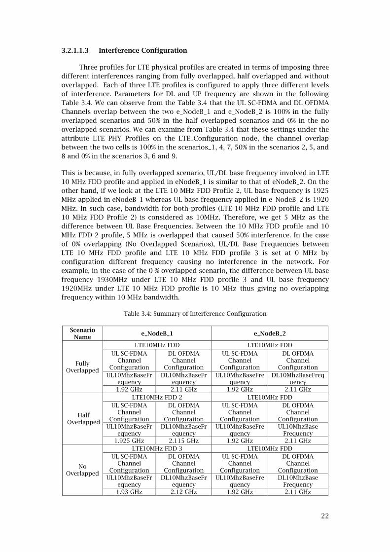
3.2.1.1.3 Interference Configuration
Three profiles for LTE physical profiles are created in terms of imposing three
different interferences ranging from fully overlapped, half overlapped and without
overlapped. Each of three LTE profiles is configured to apply three different levels
of interference. Parameters for DL and UP frequency are shown in the following
Table 3.4. We can observe from the Table 3.4 that the UL SC-FDMA and DL OFDMA
Channels overlap between the two e_NodeB_1 and e_NodeB_2 is 100% in the fully
overlapped scenarios and 50% in the half overlapped scenarios and 0% in the no
overlapped scenarios. We can examine from Table 3.4 that these settings under the
attribute LTE PHY Profiles on the LTE_Configuration node, the channel overlap
between the two cells is 100% in the scenarios_1, 4, 7, 50% in the scenarios 2, 5, and
8 and 0% in the scenarios 3, 6 and 9.
This is because, in fully overlapped scenario, UL/DL base frequency involved in LTE
10 MHz FDD profile and applied in eNodeB_1 is similar to that of eNodeB_2. On the
other hand, if we look at the LTE 10 MHz FDD Profile 2, UL base frequency is 1925
MHz applied in eNodeB_1 whereas UL base frequency applied in e_NodeB_2 is 1920
MHz. In such case, bandwidth for both profiles (LTE 10 MHz FDD profile and LTE
10 MHz FDD Profile 2) is considered as 10MHz. Therefore, we get 5 MHz as the
difference between UL Base Frequencies. Between the 10 MHz FDD profile and 10
MHz FDD 2 profile, 5 MHz is overlapped that caused 50% interference. In the case
of 0% overlapping (No Overlapped Scenarios), UL/DL Base Frequencies between
LTE 10 MHz FDD profile and LTE 10 MHz FDD profile 3 is set at 0 MHz by
configuration different frequency causing no interference in the network. For
example, in the case of the 0 % overlapped scenario, the difference between UL base
frequency 1930MHz under LTE 10 MHz FDD profile 3 and UL base frequency
1920MHz under LTE 10 MHz FDD profile is 10 MHz thus giving no overlapping
frequency within 10 MHz bandwidth.
Table 3.4: Summary of Interference Configuration
Scenario Name
e_NodeB_1 e_NodeB_2
Fully Overlapped
LTE10MHz FDD LTE10MHz FDD
UL SC-FDMA Channel
Configuration
DL OFDMA Channel
Configuration
UL SC-FDMA Channel
Configuration
DL OFDMA Channel
Configuration
UL10MhzBaseFrequency
DL10MhzBaseFrequency
UL10MhzBaseFrequency
DL10MhzBaseFrequency
1.92 GHz 2.11 GHz 1.92 GHz 2.11 GHz
Half Overlapped
LTE10MHz FDD 2 LTE10MHz FDD
UL SC-FDMA Channel
Configuration
DL OFDMA Channel
Configuration
UL SC-FDMA Channel
Configuration
DL OFDMA Channel
Configuration
UL10MhzBaseFrequency
DL10MhzBaseFrequency
UL10MhzBaseFrequency
UL10MhzBase Frequency
1.925 GHz 2.115 GHz 1.92 GHz 2.11 GHz
No Overlapped
LTE10MHz FDD 3 LTE10MHz FDD
UL SC-FDMA Channel
Configuration
DL OFDMA Channel
Configuration
UL SC-FDMA Channel
Configuration
DL OFDMA Channel
Configuration
UL10MhzBaseFrequency
DL10MhzBaseFrequency
UL10MhzBaseFrequency
DL10MhzBase Frequency
1.93 GHz 2.12 GHz 1.92 GHz 2.11 GHz

23
3.2.1.1.4 Traffic Generation
In our case, the "Application Config" node is used for generating video
conferencing traffic. For example, "video conferencing traffic (VideoConference1)"
indicates a video application performing conference using UDP protocol.
VideoConference1 will be used while creating user profiles on the "Profile Config"
object.
3.2.1.1.4.1 Application Attributes
In order to generate video traffic application definition, object has been used.
Under application definition, video conference profile is created and named as
“video conference1”. This application profile consists of various parameters
associated with frame size and frame inter-arrival time which are set according to
Table 3.5. For instance, in the low load network scenarios (1,2 and 3), source
workstations, eNodeB_mobile and eNodeB_fix both are individually generating
video conferencing traffic at the Constant Bit Rate (CBR) of 691 Kbps as of payload
at the application layer where incoming/outgoing frame size is set at 8640 bytes
with 10 frame/s while source workstations, eNodeB_mobile and eNodeB_fix, in the
medium load network scenarios ( 4, 5 and 6) are generating the video traffic at CBR
of 1036 Kbps as of payload at the application layer where incoming/outgoing
frame size is set at 12960 bytes with 10 frame/s. Thirdly, source workstations,
eNodeB_mobile and eNodeB_fix, in the high load network scenarios ( 7, 8 and 9) are
generating the video traffic at the CBR of 1382 Kbps as of payload at the
application layer where incoming/outgoing frame size is set at 17280 bytes with 10
frame/s.
Table 3.5: Video Traffic Configuration Parameters (Application Attributes)
Scenarios Profile Name Frame Size Information Payload
Scenarios (1,2 & 3)
VideoConference1
Frame Inter-arrival Time Info
10 frames/sec
691Kbps Frame Size Information
Incoming Stream
Frame Size (Bytes)
constant (8640)
Outgoing Stream
Frame Size (Bytes)
constant (8640)
Scenarios (4,5 & 6)
VideoConference1
Frame Inter-arrival Time Info
Incoming Stream
Frame Size (Bytes)
constant (12960)
1036 Kbps
Frame Size Info
Outgoing Stream
Frame Size (Bytes)
constant (12960)
Scenarios (7,8 & 9)
VideoConference1
Frame Inter-arrival Time Info
Incoming Stream
Frame Size (Bytes)
constant (17280)
1382 Kbps
Frame Size Info
Outgoing Stream
Frame Size (Bytes)
constant (17280)

24
3.2.1.1.4.2 Profile Attributes
Once application profile configuration is done, we need to configure profile
definition that deals with when traffic generating starts and ends that involved
with couple of factors. Profile Config: The "Profile Config" node is used to create
user profiles. These user profiles is then specified on LTE workstations (UE_fix,
UE_mobile, VConf_Destination_Mobile and VConf_Destination_Fix) nodes in the
network to generate video traffic. The video application (VideoConference1)
defined in the “Application Config” nobjects has been used by this object to
configure profiles (VideoConferenceProfile1) as indicated in Table 3.6. Under
profile definition, video conference has been mapped with its application profile
(videoconference1). Based on profile configuration, video conference starts at 120
seconds after simulation starts and ends at the end of simulation.
Table 3.6: Profile Definition
Name Profile Definition
Profile
Configuration
Profile Name VideoConferenceProfile1
Applications
Name VideoConference1
Start Time Offset uniform (5,10)
Duration End of Profile
Repeatability
Inter-repetition
Time
exponential
(300)
Number of
Repetitions constant (0)
Repetition
Pattern Serial
Operation Mode Serial (Ordered)
Start Time uniform (100,110)
Duration End of Simulation
Repeatability Once at Start Time
3.2.1.1.4.3 Network Load Configuration
One of the key factors of this experiment is that it considers 3 different
network loads corresponded to 9 proposed network scenarios. Varied network
loads (i.e., low, medium and high) have been realized and configured in our
simulation for better understanding of how the performance of Quality of Service
(QoS) metrics is impacted when network load is changed along with varied inter-
frequency interference and nodes mobility. Network load has been configured
followed by the configuration parameters shown in Table 3.7.
In „low‟ load network scenarios (1, 2 and 3), we have not imposed the background
traffic in which only the explicit video traffic, 691 Kbps is generated at the source
workstation (UE_fix that belongs to eNodeB_2) is contributed to the background
load 0% becoming the accumulated network load as about 7% when Uplink/Down
link capacity is considered to be 10 Mbps.
In „medium‟ network load scenarios (4, 5 and 6), 10% explicit traffic generated at
source workstation UE_fix and 40% background traffic have been imposed. In order
to impose background traffic „ip_traffic_flow‟ object is used representing the IP

25
layer traffic flow between the designated source (UE_fix) and the corresponding
eNodeB_2. Combining both explicit and background load contributes to the overall
network load as about 50%.
In „high‟ network load scenarios (7, 8 and 9), 15% explicit traffic generated at the
source workstation UE_fix and 95% background traffic imposed by „ip_traffic_flow
have contributed to the overall network load of 110% and considered as high load
network scenarios.
Table 3.7: Network Configuration
Scenarios
Uplink/Down
Link Load
(Explicit
Network Load)
Uplink/Down
Link Capacity
Background
Traffic
Network
Load
Scenario_1, 2 ,
3
(LowLoad)
691 Kbps 10 Mbps 0% 7%
Scenario_4, 5, 6
(MediumLoad) 1036 Kbps 10 Mbps 40% 50%
Scenario_7, 8, 9
(HighLoad) 1382 Kbps 10Mbps 95% 110%
3.2.1.1.5 Video Conferencing Pair Configuration
The two conference pair has been configured so that each pair can have a
single conference session (UE_mobile<->VConf_Destination_mobile) and (UE_fix<->
VConf_Destination_fix).
Figure 19: Mobility and Application deployment (Referred to Scenarios 1 to 9)

26
3.2.1.1.6 Mobility Configuration by using trajectory settings
3.2.1.1.6.1 Trajectory Control in OPNET Modeler
System performance of wireless technologies is likely to be affected by
various factors such as distance, line-of-sight, and other mobility-related
characteristics. So, modeling an efficient mobile node and its mobility is very
critical while carrying out some simulation work of the wireless communications in
OPNET platform. In order to control node‟s mobility, OPNET Modeler provides
several ways. Mobility can be changed based on predefined trajectories or
randomly selected path. Trajectory refers to the path specification for mobile
nodes‟ movement over the course of the simulation. There are two ways of
assigning the node mobility [37].
Segment-Based Trajectories define movement using a series of pre-defined
points.
Vector-Based Trajectories define movement in terms of a bearing, ground
speed, and ascent Rate.
3.2.1.1.6.1.1 Segment-based trajectory
In our study, we have used the segment-based variable-interval trajectory for
controlling the node‟s movement. There are two types of segment-based
trajectories which include fixed interval and variable-interval trajectories. In a
fixed-interval trajectory, only one value determines the traversal time for all
segments, hence a node takes the same amount to time to traverse every segment,
regardless of the segment‟s length. On the other hand, in the choice of selecting
the segment-based trajectory, the structure of the variable-interval trajectory
shown in figure 20 is realized to be a suitable for this research work. A segment-
based trajectory consists of one or more points that define the mobile node‟s
mobility along with a set of three-dimensional (x, y, altitude) coordinates.
Trajectory with variable-length segments is defined using a set of angles (roll,
pitch, and yaw) that determines the mobile node‟s orientation in space. Segment-
based trajectory is stored in ASCII text file with a .trj extension [37], [38]. The *.trj
file for variable interval trajectory has following structure:
Version: 5
Position_Unit: <position_unit>
Altitude_Unit: <altitude_unit>
Coordinate_Method: <coordinate_method>
locale: <locale>
Calendar_Start: <start_time>
Coordinate_Count: <coordinate_count>
# X Position ,Y Position ,Altitude ,Traverse Time, Wait Time, Pitch, Yaw,Roll
<x_coord_0>,<y_coord_0>,<alt_0>,<trav_time_0>,<wait_time_0>,<pitch_0>,<yaw_0>,
<roll_0)><x_coord_1>,<y_coord_1>,<alt_1>,<trav_time_1>,<wait_time_1>,<pitch_1>,
<yaw_1>,<roll_1)><x_coord_n>,<y_coord_n>,<alt_n>,<trav_time_n>,<wait_time_n>,<
pitch_n>,<yaw_n>,<roll_n)>
Figure 20: Variable-Interval Trajectory File Format

27
3.2.1.1.6.1.1.1 Relative movement
Parent sub-network itself can be mobile while the mobile node, as a child
node under the parent sub-network, can also have mobility. That means the mobile
node and its subnet both can be mobile. In addition to our desired network
scenario, parent sub-network is considered to be stationary whereas only its child
node‟s (UE_mobile) position are changed over the course of simulation time based
on the predefined trajectory [37].
3.2.1.1.6.1.1.2 Defining segment-based trajectories
The segment-based trajectory can be created and assigned manually in OPNET
Modeler. Therefore, for the purpose of our work, we have manually created
trajectory as described in variable-length segment-based trajectory file format
depicted in Figure 20 and Table 3.8.
Figure 21: Define Trajectory Dialog Box
The Trajectory file named „lte_intf‟ is configured followed by Table3.8 and Variable-
Interval Trajectory File Format presented in Figure 20. According to the
predetermined Trajectory configuration parameters shown in Table3.8, four
coordinates are considered and their corresponding position-based locations have
been defined. To form a Trajectory, three segments have been considered. Looking
at the Figure 22 and Table3.8, we can see that UE_mobile node‟s initial x position
and y position specified in its parent sub-network are set to (0.000 km) and (0.000
km), respectively. In terms of using coordinates_method, we have used „relative‟
method in which x and y coordinates are interpreted as offsets from the UE_mobile
node‟s initial position relative to its parent sub-network. That is why its first
position is kept (0.00 km/hr, 0.00 km/hr). „Distance‟, „Traverse Time‟ and „Ground
Speed‟ for the first position (0.00 km/hr, 0.00 km/hr) of UE_mobile is considered to
be not applicable. UE_mobile node‟s altitude is set to 0m specifying its elevation
relative to the sea level, the underlying terrain, or the parent sub-network. The
„Wait Time‟ presented in Table3.8 is responsible to keep UE_mobile on hold for 2
minutes 20 seconds. The “Pitch” value has been set to „Auto computed‟ such that
node orientation matches the motion vector for each trajectory segment. “Roll”
Value is assigned to „unspecified‟ referring to the same as 0 degrees. That means, 0
degrees refer to the parallel to the ground. “Yaw” value is set to „autocomputed‟
which will set such that UE_mobile orientation matches the motion vector for each
trajectory.

28
During the OPNET simulation run, UE_mobile moves based on assigned trajectory
configuration. After the simulation is started, UE_mobile waits 2 minutes 20
seconds at its initial position (0.00 km, 0.00 km). Following the above description
related to the first position of UE_mobile, we can see from trajectory settings
indicated in Figure 22 and Table3.8, UE_mobile moves about 2.44 km towards the
position (-2.162 km, -1.137 km) from its first position (0.0 km, 0.0 km) where
traverse time is 1 minute 31.11 seconds attaining the ground speed of UE_mobile,
96.55 kilometers per hour (km/hr). UE_mobile stays there (for 10 seconds and then
starts travelling at the ground speed of 96.55 km/hr for another about 1minute
0.59 second. At this point, after waiting for another 10 seconds it travels for 40.55
seconds at the ground speed of 96.56 km/hr.
Table 3.8: LTE Trajectory
Version: 5
Position_Unit: Kilometers (Specifies how the x_coord_n and y_coord_n values of positions
are interpreted)
Altitude_Unit: Meters
Coordinate_Method: relative
Altitude_Method: absolute
Locale: C (i.e., Reserved for future use. The only valid value is "C".)
Calendar_Start: unused
Coordinate_Count: 4
X Pos
(km)
Y Pos
(km)
Dista
nce
(km)
Alt
itu
de
(m)
Travers
e Time
(s)
Ground
Speed
(km/hr)
Wait
Time
(s)
Accumu
lated
Time (s)
Pitch
(Degrees)
Yaw
(Degrees)
Roll
(Degre
es)
0.000 0.000 n/a 0 n/a n/a 140 140 Autocompute
d
Autocom
puted
Unspe
cified
2.162 1.137 2.44 0 91.11 96.55 10 241.11 Autocompute
d
Autocom
puted
Unspe
cified
0.550 0.937 1.62 0 60.59 96.55 10 311.70 Autocomp-
uted
Autocom-
puted
Unspe
cified
0.312 0.275 1.08 0 40.55 96.56 10 362.25 Autocomp-
uted
Autocom
puted
Unspe
cified
Figure 22: Trajectory Settings

29
3.2.2 Network Modeling and Configuration all Nine Scenarios
Network topology depicted in Figure 18 represents our proposed baseline
network model in which all of general configuration has been discussed. In this
section, detailed description of each network scenario will be illustrated. Our
proposed network models presented in figure18 corresponds to all of nine network
scenarios except varying interference and network load. Scenarios (1, 2 and 3) have
been implemented to compare with the study results from other scenarios (e.g. 4,
5, 6, 7, 8 and 9). Scenarios are given as follows.
a) Scenario1_FDD10MHz_LowLoad_FullyOverlapped
b) Scenario2_FDD10MHz_LowLoad_HalfOverlapped
c) Scenario3_FDD10MHz_LowLoad_NoOverlapped
d) Scenario4_FDD10MHz_MediumLoad_FullyOverlapped
e) Scenario5_FDD10MHz_MediumLoad_HalfOverlapped
f) Scenario6_FDD10MHz_MediumLoad_NoOverlapped
g) Scenario7_FDD10MHz_HighLoad_FullyOverlapped
h) Scenario8_FDD10MHz_HighLoad_HalfOverlapped
i) Scenario9_FDD10MHz_HighLoad_NoOverlapped
3.2.2.1 Scenario1_FDD10MHz_LowLoad_FullyOverlapped
This scenario is replicated from the baseline scenario. Two important things
have been taken into account while modeling this network. First, network load
depicted in Table 3.10 and Figure 24 is kept low that means, video traffic is
generated at the rate of 10 frames/Sec while frame size of 8640 bytes is
contributed to the generated traffic rate of 691 Kbps by a single UE (UE_mobile)
without additional layer protocol overhead. The same amount of video traffic is
generated by UE_fix. Another major thing is the interference which has been
elaborately discussed under the Interference Configuration (i.e., Section 1.1.1.1.3).
Detail configuration parameters for 100% overlapped scenario can be found in
Table 3.9 and Figure 23.
Table 3.9: Fully overlapped configuration parameters
e_NodeB_1 e_NodeB_2
LTE10MHz FDD LTE10MHz FDD
UL SC-FDMA Channel
Configuration
DL OFDMA Channel
Configuration
UL SC-FDMA Channel
Configuration
DL OFDMA
Channel
Configuration
UL10MhzBase
Frequency
DL10MhzBase
Frequency
UL10MhzBase
Frequency
DL10MhzBase
Frequency
1.92 GHz 2.11 GHz 1.92 GHz 2.11 GHz

30
Figure 23: Scenario_1_FDD10MHzFullyOverlapped (i.e., Similar LTE 10 MHz FDD
Profitoconfiguration applied for scenarios 4 and 7)
Table 3.10: Low Network Load Configuration (Details description related to the network load
referred to the section (3.2.1.1.4.3 Network Load configuration).
Scenario_1, 2 and 3 Uplink/Down
Link Load
Up/DownLink
Capacity
Background
Traffic
Network
Load
Scenario_1, 2,3
(Low Load) 691 Kbps 10 Mbps 0% 7%
Figure 24: Scenario1_ FDD10MHz_LowLoad_FullyOverLapped (similar configuration indicated
by green colored box applicable for scenario_2 and 3)

31
3.2.2.2 Scenario2_FDD10MHz_LowLoad_HalfOverlapped
This scenario_2 (i.e., Scenario2_FDD10MHz_LowLoad_HalfOverlapped) is replicated
from the scenario_1. All the configuration parameters used in scenario_1 are kept
same except the level of interference imposed on it. Please see Section 1.1.1.1.3
(Interference configuration) on how 50% interference has been configured. Table
3.11 and Figure 25 represent settings for interference configuration parameters
and how LTE 10 MHz FDD profiles are assigned to the network.
Table 3.11: Half overlapped configuration parameters
e_NodeB_1 e_NodeB_2
Half Overlap
ped
LTE10MHz FDD 2 LTE10MHz FDD
UL SC-FDMA Channel
Configuration
DL OFDMA Channel
Configuration
UL SC-FDMA Channel
Configuration
DL OFDMA Channel
Configuration
UL10MhzBaseFrequency
DL10MhzBaseFrequency
UL10MhzBaseFrequency
UL10MhzBaseFrequency
1.925 GHz 2.115 GHz 1.92 GHz 1.92 GHz
Figure 25: Scenario_2_FDD10MHz_Low Load_Half Overlapped (i.e., Similar LTE 10 MHz FDD
Profitoconfiguration applied for scenarios 5 and 8)
3.2.2.3 Scenario3_FDD10MHz_LowLoad_NoOverlapped
This scenario_3 (i.e., Scenario3_FDD10MHz_LowLoad_NoOverlapped) is
replicated from the scenario_2. All the configuration parameters used in scenario_2
are kept same except the level of interference imposed on it. Please see Section
1.1.1.1.3 (Interference configuration) on how 0% interference has been configured.
Table 3.12 and Figure 26 represent settings for interference configuration
parameters and how LTE 10 MHz FDD profiles are assigned to the network.

32
Table 3.12: 0% (No Interference) overlapped configuration parameters
NoOverl
apped
e_NodeB_1 e_NodeB_2
LTE10MHz FDD 3 LTE10MHz FDD
UL SC-FDMA
Channel
Configuration
DL OFDMA
Channel
Configuration
UL SC-FDMA
Channel
Configuration
DL OFDMA
Channel
Configuration
UL10MHzBaseFre
quency
DL10MHzBaseFre
quency
UL10MHzBaseFre
quency
DL10MHzBaseFr
equency
1.93 GHz 2.12 GHz 1.92 GHz 2.11 GHz
Figure 26: Scenario_3_FDD10MHz_LowLoad_NoOverlapped (i.e., Similar LTE 10 MHz FDD Profile configuration applied for scenarios 6 and 9)
3.2.2.4 Scenario4_FDD10MHz_MediumLoad_FullyOverlapped
This scenario_4 (i.e., Scenario4_FDD10MHz_MediumLoad_HalfOverlapped) is
replicated from the scenario_1. All the configuration parameters used in
scenario_1 is kept same except the network load changed from low load to
medium load (see detail parameters in Table 3.13 configured for medium network
load.
Table 3.13: Medium network load parameters (Detailed description related to the network
load referred to the section 3.2.1.1.4.3 Network Load configuration).
Scenario_4 Uplink/Down Link
Load
Uplink/Down Link
Capacity
Background
Traffic
Network
Load
Scenario_4,
5,6 (Medium
Load)
1036 Kbps 10 Mbps 40% 50%

33
Figure 27: Scenario4_FDD10MHz_MediumLoad_FullyOverlapped (settings for video
conferencing traffic configuration applied to scenarios 5 and 6)
3.2.2.5 Scenario5_FDD10MHz_Medium Load_HalfOverlapped
Scenario_5 is replicated using scenario_4 and imposing 50% interference
according to the interference configuration parameters described in scenario_2.
3.2.2.6 Scenario6_FDD10MHz_Medium Load_No Overlapped
Scenario_6 is replicated using scenario_5 and imposing 0% interference
according to the interference configuration parameters described in scenario_2.
3.2.2.7 Scenario7_FDD10MHz_High Load_FullyOverlapped
Scenarios 7 have been modeled followed by scenario 1 except the high traffic
load imposed in this case. Detail configured parameters can be found in Table 3.14
and Figure 28.
Table 3.14: Detailnetwork load configuration parameters ((Details description related to the
network load referred to the section (3.2.1.1.4.3 Network Load configuration).
Scenarios_7 Uplink/DownLink
Load
Uplink/DownLink
Capacity
Background
Traffic
Network
load
Scenario_7,
8,9 (High load) 1382 Kbps 10Mbps 95% 110%

34
Figure 28 : Scenario4_FDD10MHz_HighLoad_FullyOverlapped (settings for video
conferencing traffic configuration applied to scenarios (8 and 9)
3.2.2.8 Scenario8_FDD10MHz_HighLoad_HalfOverlapped
Scenario_8 is replicated using scenario_7. Network load for Scenario_8 is kept
same as scenario_7 that means parameters for high network load configuration has
been similar to scenario_7 and 50% interference is imposed in scnenario_8
following the interference configuration outlined in scenario_2.
3.2.2.9 Scenario9_FDD10MHz_HighLoad_NoOverlapped
Scenario_9 is replicated using scenario_8. Network load for Scenario_9 is kept
same as scenario_8 that means parameters for high network load configuration has
been similar to scenario_8 and 0% interference is imposed in scnenario_9 following
the interference configuration outlined in scenario_3.
3.3 Simulation Run
All the simulations run for 480 seconds, and all applications that generate the
traffic (i.e. Video conferencing) starts simultaneously at 120 seconds of the
simulated time, that is, every event has the same probability to occur at every value
at 120 seconds. The simulation is implemented in OPNET Modeler 17.1 running on
an HP laptop with Windows 7, Pentium IV 1.7 GHz with 2GB of RAM. These
information regarding nine different scenarios has been collected from OPNET
after the simulation run is finished.
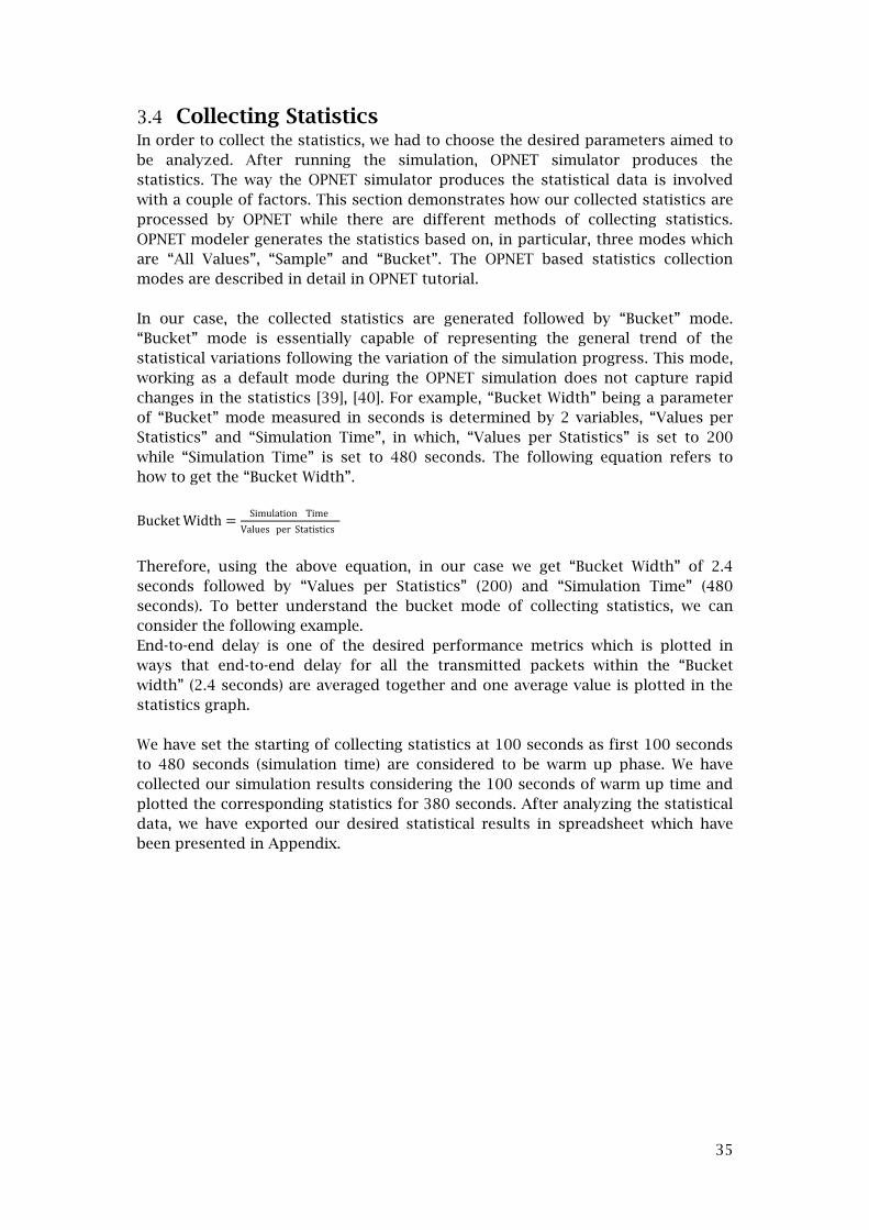
35
3.4 Collecting Statistics In order to collect the statistics, we had to choose the desired parameters aimed to
be analyzed. After running the simulation, OPNET simulator produces the
statistics. The way the OPNET simulator produces the statistical data is involved
with a couple of factors. This section demonstrates how our collected statistics are
processed by OPNET while there are different methods of collecting statistics.
OPNET modeler generates the statistics based on, in particular, three modes which
are “All Values”, “Sample” and “Bucket”. The OPNET based statistics collection
modes are described in detail in OPNET tutorial.
In our case, the collected statistics are generated followed by “Bucket” mode.
“Bucket” mode is essentially capable of representing the general trend of the
statistical variations following the variation of the simulation progress. This mode,
working as a default mode during the OPNET simulation does not capture rapid
changes in the statistics [39], [40]. For example, “Bucket Width” being a parameter
of “Bucket” mode measured in seconds is determined by 2 variables, “Values per
Statistics” and “Simulation Time”, in which, “Values per Statistics” is set to 200
while “Simulation Time” is set to 480 seconds. The following equation refers to
how to get the “Bucket Width”.
Bucket Width =Simulation Time
Values per Statistics
Therefore, using the above equation, in our case we get “Bucket Width” of 2.4
seconds followed by “Values per Statistics” (200) and “Simulation Time” (480
seconds). To better understand the bucket mode of collecting statistics, we can
consider the following example.
End-to-end delay is one of the desired performance metrics which is plotted in
ways that end-to-end delay for all the transmitted packets within the “Bucket
width” (2.4 seconds) are averaged together and one average value is plotted in the
statistics graph.
We have set the starting of collecting statistics at 100 seconds as first 100 seconds
to 480 seconds (simulation time) are considered to be warm up phase. We have
collected our simulation results considering the 100 seconds of warm up time and
plotted the corresponding statistics for 380 seconds. After analyzing the statistical
data, we have exported our desired statistical results in spreadsheet which have
been presented in Appendix.

36
LT
E P
HY
Up
lin
k S
NR
(d
B)
4 CHAPTER FOUR RESULTS ANALYSIS AND EVALUATION
In this chapter, simulation results are discussed for the different network
scenarios. Section 4.1 offers a discussion that regards to the performance of
uplink SNR while section 4.2 covers the evaluation of uplink retransmission
performance. Section 4.3 discusses on the performance of end-to-end delay (i.e.
E2E delay).
4.1 Performance of LTE PHY Uplink SNR (dB)
SNR (Signal-to-noise ratio) is calculated by the power ratio between a
signal and the background noise.
𝑆𝑁𝑅 =𝑃𝑠𝑖𝑔𝑛𝑎𝑙
𝑃𝑛𝑜𝑖𝑠𝑒
Where, P is average power.
It is important to mention that the following sub-sections under section 4.1, we will
discuss about the performance of Uplink SNR in which Uplink SNR attained by
UE_mobile and UE_fix nodes in all 9 different scenarios have been plotted. We have
considered first 110 seconds of simulation time, 480 as a warm up time, therefore
video application starts at around 110 seconds of the simulation time and plotted
accordingly. The statistics collecting method suggested in the OPNET Modeler
environment has been elaborately described in section 3.4 under chapter 3.
4.1.1 Performance of LTE PHY Uplink SNR (dB) for low- load
network scenarios-1, 2, 3
Simulation Time (Sec)
Figure 29: LTE PHY Uplink SNR (dB) for Scenarios-1, 2, 3

37
The Uplink SNR (dB) depicted in Figure 29 shows the comparative performance of
Uplink SNR (dB) for the corresponding user equipments (UE_mobile and UE_fix)
under low load network scenarios. In Scenario1 (100% inter-frequency overlapped),
we can see that both the UE_fixed and the UE_mobile experience worst
performance in terms of attaining high Uplink SNR (dB) as the UL SC-FDMA and DL-
OFDMA channels overlap between the two e_NodeB_1 (connected with UE_mobile)
and e_NodeB_2 (connected with UE_fix). However, UE_mobile for fully overlapped
scenario experiences less Uplink SNR, approximately 10 dB whereas UE_fix
experiences about 20 dB Uplink SNR. In such case, the performance of Uplink SNR
is impacted by two factors such as inter-frequency interference and nodes‟
mobility. That means for the same scenario, it is found that UE_fix always
maintains higher Uplink SNR compared with UE_mobile.
In scenario 2 when 50% interference is imposed, we can observe that Uplink SNR
for UE_mobile (yellow line) experiences about 25 dB until 2 minutes 20 seconds of
the simulation time. Afterwards, the Uplink SNR for UE_mobile (yellow line) is
gradually decreased attaining the lowest 13 dB, then again it starts increasing from
5 minutes 12 seconds of the simulation time. After about 6 minutes Uplink SNR for
UE_mobile is steadily increased attaining about 18 dB. It is noted that during the
mobility period of UE_mobile, from 2 minutes 20 seconds to 6 minutes 2 seconds,
the Uplink SNR for UE_mobile has fallen considerably whereas Uplink SNR for
UE_fix (red line) constantly maintains about 27 dB.
Scenario 3 (i.e., 0% frequency interference), UE_fix (green line) outperforms
UE_mobile‟s Uplink SNR (pink line) by achieving about 36 dB being the highest
Uplink SNR compared with all 3 scenarios. It should be mentioned that Uplink SNR
for UE_mobile (pink line) follows the similar trend in its performance suffering an
extreme drop in attaining strong Uplink SNR, implying that UE_mobile moves away
from its corresponding eNodeB_2. Thus the signal strength becomes weaker
causing the Uplink SNR performances of UEs to be worsened during the mobility
period (2 minutes 20 seconds to 6 minutes 2 seconds).
4.1.2 Performance of LTE PHY Uplink SNR (dB) for medium-load
network scenarios-4, 5, 6 Scenario 4 corresponds to fully overlapped (100% interference imposed)
considering the medium network load while scenario5 refers to half overlapped
(50% interference imposed), and scenario 6 represents the no frequency
overlapping (0% interference imposed).
In the scenario 4 (100% interference imposed), Uplink SNR for UE_mobile
(cyan line) shows a downward trend starting at about 2 minutes 20 seconds of the
simulation time. This downward trend continues until about 5 minutes 10 seconds
of the simulation time reaching the lowest Uplink SNR (about 7dB) as UE_mobile
node moves away from its corresponding eNodeB_2. At this point of simulation
period, a gradual upward trend is noticed from there on attaining the highest
Uplink SNR (12 dB). In contrast, the Uplink SNR for UE_fix (blue line) maintains a
steady trend until the end of the simulation attaining about 17 dB.

38
LT
E P
HY
Up
lin
k S
NR
(d
B)
Simulation Time (Sec)
Figure 30: LTE PHY Uplink SNR (dB) for Scenarios-4, 5, 6
Figure 30 shows a comparative performance of Uplink SNR (dB) attained by user
equipments (UE_mobile and UE_fix nodes) for 3 different scenarios (4, 5 and 6).
In scenario 5 (50% interference imposed), Uplink SNR for UE_mobile (yellow line)
shows a similar trend compared with Uplink SNR of UE_mobile (cyan line) in
scenario4. When comparing between Uplink SNR of UE_fix (red line) and Uplink SNR
of UE_mobile (yellow line), it is found that the Uplink SNR of UE_fix (red line)
remains steady attaining about 25 dB and being higher than that of the Uplink SNR
of UE_mobile.
In scenario 6 (0% interference imposed), Uplink SNR performance of UE_mobile
(pink line) shows the similar trend compared with scenarios 4 and 5 but it achieves
higher SNR than that of those scenarios as it does not experience frequency
overlapping but it is only impacted by its mobility. SNR for UE_fix (green line)
shows the straight line that means it does achieve the highest Uplink SNR
compared with all the other scenarios.
To sum up, in all three scenarios the fluctuations for the UE_fix nodes is less
because they do not suffer from any path loss due to their immobility. On the other
hand, being in motion, the UE_Mobile nodes face greater interference and do not
have constant solid lines. The constant green line demonstrates the UE with the
best performance as there is no frequency overlap and as it is immobile. Worst
possible performance can be expected from the fully overlapped cyan curve which
is in motion thus giving the lowest SNR, 9 dB.

39
LT
E P
HY
Up
lin
k S
NR
(d
B)
4.1.3 Performance of LTE PHY Uplink SNR (dB) for high- load
network scenarios-7, 8, 9
Simulation Time (Sec)
Figure 31: LTE PHY Uplink SNR (dB) for Scenarios-7, 8, 9
The Uplink SNR graphs above show the performances of the Uplink SNRs for UEs
under high load.
Looking at Figure 31, we can observe that in Scenario 7, when there are 100%
frequencies overlap, the UE_mobile (yellow line) faces the worst SNR performance
compared to the UE_fix (blue line). 100% interference and mobility cause
UE_mobile experiencing such SNR. On the other hand, Uplink SNR of UE_fix shows
a sudden drop (about 18dB) stated at the simulation time of 2 minutes 20 seconds,
remains steady for a minute, then starts slowly increasing until the end of
simulation achieving 32 dB. We notice that for low and medium load scenarios
illustrated in the above subsequent sections, the steady and straight line for Uplink
SNR of UE_fix has been experienced, even this trend is found with scenarios of
100% and 50% interference. But when network load is increased as scenario7 with
100% interference, given that it does not maintain a steady performance rather we
believe that the fluctuation in the SNR of UE_fix is caused by bigger incoming and
outgoing frame sizes along with background load, if mobility and interferences are
not taken as the performance impacting factor which is the case in the scenario7
for UE_fix as well as UE_mobile.
In case of Scenario 8 (50% interference imposed), the UE_mobile (cyan line) is found
to experience the lowest SNR (10 dB) at the simulation time of 3 minutes, then it
sharply increases and reaches up to approximately 25 dB at the end of the
simulation. Uplink SNR of UE_fix (red line) steadily maintains about 25 dB which is
not differed from UE_mobile but during the mobility period (from 2 minutes 20
seconds to 6 minutes 11 seconds of the simulation time), UE_mobile has no
consistency as the lowest dB ratio is observed for the high load network scenario.
In scenario 9 (no interference) dB ratio remains constant for high load for UE_fix
(green line) but dB ratio in UE_fix is higher than UE_mobile (pink line).

40
HA
RQ
UL R
etr
an
sm
issio
n R
ate
(
pack
ets
/sec)
4.2 Performance of LTE HARQ UL Retransmission Rate
Retransmission refers to resending the damaged or lost packets in
computer network communication. It is one of the basic mechanisms that operate
over a packet switched computer network used by protocols. The objective of this
mechanism is to establish a reliable communication in computer networks. It is
essentially identical to the Automatic Repeat request (ARQ). ARQ, an error
detection technique consisting of retransmission principles is used to minimize
packet transmission errors that take place in the LTE network. An improved
version of the ARQ is called Hybrid Automatic Repeat request (HARQ). ARQ lacks
error correction if anything goes wrong with the transmitted packets. On the other
hand, HARQ is capable of detecting the errors and eventually correcting if
transmitted packets are lost on the way to its destination [25].
4.2.1 Performance of LTE HARQ UL Retransmission Rate for low-
load network scenarios-1, 2 and 3
Prior to get into the discussion of HARQ UL retransmission performance
analysis, it is required to mention that two HARQ parameters configured in the
proposed-simulated network include uplink and downlink parameters. Uplink and
downlink parameters both are set to the same value as of 3. That means three
attempts of retransmission for an HARQ packet will be taken before the packets
are discarded in our study. In OPNET environment, HARQ uplink retransmission
rate (packet/Sec) is an important performance metric which has been investigated
and discussed in the following section.
Simulation Time (Sec)
Figure 32: LTE HARQ Rate (packets/Sec) for Scenarios-1, 2, 3
Figure 32 shows retransmission rates of UE_mobile and UE_fix nodes under low
network load. Some packets may be lost on the way before reaching the receiver
due to interference or path loss; these packets need to be retransmitted. Higher
packet retransmission resembles worse network performance in terms of delay.
Retransmission does recover the lost packet giving reliability at the expense of
adding additional delay to the missing packets. We will discuss the performance of
end-to-end delay impacted by such retransmission in section 4.3.

41
The graph shows that the UE_mobile (cyan line) of fully overlapped case in
scenario1 has the highest rate of retransmission which is due to the highest packet
loss in comparison to the retransmission rate for UE_fix. It is noticed that during
the period of mobility (from 2 minutes 20 seconds to 6 minutes 10 seconds),
UE_mobile experiences the maximum retransmission rate of 400 packet/Sec while
the UE_fix, in spite of facing 100% interference, does not require to retransmit the
packet as no packet is lost. For this reason there is no retransmission required by
UE_fix, causing the rate to be as low as zero. It can be seen from the above graph
that at the simulation time of 2 minutes 40 seconds packet retransmission starts,
exponentially increases for a minute, stays constant for about 30 seconds, and
again starts slowly decreasing reaching the retransmission rate of 0 packets/sac at
about 5 minutes 30 seconds of the simulation time.
To better understand how such retransmission trend is developed over the
simulation time, we need to analyze the movement of UE_mobile which moves
based on assigned trajectory configuration illustrated in chapter 3. In such a case,
after the simulation is started, UE_mobile waits 2 minutes 20 seconds at its initial
position (0.00 km, 0.00 km) and moves about 2.44 km from there on towards the
position (-2.162 km, -1.137 km) at the ground speed of UE_mobile, 96.55 km/hr.
UE_mobile stays there (for 10 seconds and then starts travelling at the ground
speed of 96.55 km/hr for another about 1minute 0.59 second. At this point, after
waiting for another 10 seconds it travels for 40.55 seconds at the ground speed of
96.56 km/hr. The mobility pattern corresponded to the assigned trajectory and
degree of inter-frequency interference has contributed to the overall trend of the
HARQ uplink retransmission rate (cyan line). The results seem to be for the UL
retransmission rate caused by two factors, of which the one is high speed of node‟s
mobility and as it becomes closer to the adjacent cell (eNodeB_1), the degree of
inter-frequency interference gets increased as a result the more packets get lost
leading the packets to be retransmitted as the case happened with our findings.
During the mobility period, a similar trend of the retransmission rate for
UE_mobile (yellow line) in scenario2 (50% interference) is found attaining a
relatively less retransmission rate of about 330 packets/Sec compared with that of
about 400 packets for UE_mobile (cyan line) in scenario2 (100% interference). The
trend of retransmission is found to be almost similar to that of scenairo1‟s
UE_mobile.
That means UE_fix hardly an experiences packet loss when even 50% interference
imposed on the network. No retransmitted packets are found either for UE_mobile
and UE-fix in scenario3 as this network has 0% interference.
4.2.2 Performance of LTE HARQ UL Retransmission Rate for
medium-load network scenarios-4, 5, 6
Figure 33 shows the rate of uplink retransmissions rates of UE_mobile and
UE_fix for scenarios (4, 5, and 6) under high network load condition.

42
HA
RQ
UL R
etr
an
sm
issio
n R
ate
(pack
ets
/sec)
Simulation Time (Sec)
Figure 33: LTE HARQ UL Retransmission Rate (packets/Sec) for Scenarios-4, 5, 6
We can observe from Figure 33 that during the simulation period ranging from
about 2 minutes 40 seconds to 5 minutes 20 seconds, the UE (cyan line) with the
highest rate of retransmissions turns out to be mobile as it faces 100% interference
and travels at the speed of 96 km/sec, and endures highest packet loss attaining
the average retransmission rate of about 530 packets/sec whereas UE_fix hardly
experiences packet loss, 0.003 packets/sec which is negligible as according to ITU
standard 1% packet loss is tolerable for video traffic when maintaining a good
quality of video call.
The UE_mobile in scenario 5 (50% interference) has the second highest HARQ UL
Retransmission Rate (packets/sec). At the simulation period of around 3 minutes to
4 minutes 40 seconds, the curve is hitting it peak rate of retransmission rate,
which implies that during 2 minutes 20 seconds to 5 minutes 10 seconds after
simulation starts , the UE is being moved quite far away from its respective
eNodeB_2 resulting in stronger interference. Due to its immobility, the packet loss
for UE_fix of scenario5 is closed to null.
In Scenario 6, both UEs (UE_mobile and UE_fix) experience no packet loss resulting
in no uplink retransmission.
4.2.3 Performance of LTE HARQ UL Retransmission Rate for high-
load network scenarios-7, 8, 9
This is high load network scenarios (7, 8 and 9). We should notice that
retransmission rate went closed to zero after the simulation time of 3 minutes for
UE_mobile (scenario7 (100% interference). But at the beginning of simulation time
at about 2 minutes 20 seconds it reaches up to the maximum of 50 retransmission
rate of 600 packets/Sec then it goes to closely zero retransmission rate. This is due
to the fact that during the mobility period, (total of 3 minutes and 50 seconds
accounted to the simulation time 2 minutes 20 seconds after the simulation is
started), there is no packet transmission happened, all the packets dropped on the
way of its destination.

43
HA
RQ
UL R
etr
an
sm
issio
n R
ate
(pack
ets
/sec)
Simulation Time (Sec)
Figure 34: LTE HARQ UL Retransmission Rate (packets/Sec) for Scenarios-7, 8, 9
We believe this is very important findings subjected to the uplink retransmission
rate in high load network. In order to validate our findings, we need to analyze the
retransmission rates previously mentioned in subsections (4.2.1 and 4.2.2)
corresponded to the low and medium network load scenarios, respectively. For
example, in the low and medium load networks, we found that the uplink
retransmission rate develops almost a similar trend particularly during the
mobility period except medium load network contributed to higher retransmission
rate than low load network for UE_mobile. UE_mobile in a medium load network
has a more retransmission rate than that of the low network load.
There are two cases that need to be analyzed. We found that UE_mobile (100%
interference, high load) can tolerate such network condition for one minute (from 2
minutes 20 seconds to about 3 minutes of the simulation time). On the other hand,
tolerance time of the retransmission starting from 2 minutes 20 seconds to about 3
minutes 30 seconds for UE_mobile (50 % interference and high load) is 30 seconds
higher than 100% interfered network. Both about 100% and 50 % interfered
networks have reached the maximum retransmission rate of 600packets/Sec.
Afterward, that means from 3 minutes for 100 % interfered network and about 3
minutes 30 seconds for 50% interfered network to 6 minutes 10 seconds of the
simulation, all the packets are discarded leading all the packets dropped.
We also need to mention that we considered many different incoming and outgoing
frame sizes for generating video conference traffic, it turned out, UE_fix for the
same configuration does not experience packet loss leading no retransmission
experienced but UE_mobile for the same configuration (100 % interference,
mobility, and high network load) contributed in the drop of all the packets during
the mobility period. Again, it is noted that frame size of video traffic for high load
network are considered to be 17280 bytes (10 frame per second) where for low and
medium load network scenarios both incoming and outgoing frame sizes are
considered to be 8640 bytes and 12960 bytes (10 frames/Sec), respectively.
Dropping all the packets can be found from the results for packet sent/received
graphs described in the following subsequent section.

44
4.3 Performance of Packet End-to-End (e2e) Delay and
Video Conference Traffic Sent/Received
It is important to mention that for the sake of better understanding and
analyzing how the packet end-to-end (e2e) delay is impacted by network loads,
intensity of interference and mobility, packet loss (packet sent/received) graphs are
taken in consideration in the following sections.
In the case of e2e delay, the time that takes a packet to travel from User Equipment
(source) to User Equipment (destination) is called e2e delay and it is measured in
seconds. e2e delay is a fundamental criterion to assess network performance, in
addition to measure the quality of service QoS) from end users. There are three
sorts of delay occurred i.e. sender delay, network delay and receiver delay, when
packets are transferred from source to destination. After a packet is sent, it is not
received immediately, rather there is a delay before it can be dispatched. The
difference between the time of sending a packet and the time of receiving it is
called e2e delay.
Packet loss occurs when one or more packets fail to reach their respective
destination. The packet is determined followed by the following equation.
𝑃𝑎𝑐𝑘𝑒𝑡 𝑙𝑜𝑠𝑠 =𝑆𝑒𝑛𝑡 𝑃𝑎𝑐𝑘𝑒𝑡 − 𝑅𝑒𝑐𝑒𝑖𝑣𝑒𝑑 𝑃𝑎𝑐𝑘𝑒𝑡
𝑆𝑒𝑛𝑡 𝑃𝑎𝑐𝑘𝑒𝑡 ∗ 100
4.3.1 Performance of Packet End-to-End Delay (Sec) and Video
Traffic Packet Sent/Received (packet/Sec) for low-load
network scenarios-1, 2, 3
Simulation Time (Min) (a) Simulation Time (Sec) (b)
Figure 35: (a) Packet End-to-End Delay Packet Received and (b) Video Conference Packet Sent
for Scenarios-1, 2, 3
Figure 35 (a) shows packet e2e delays during video conferences while Figure 36 (b)
presents the traffic sent and received during video conferencing under low load.

45
4.3.1.1 Video Traffic Packet Sent/Received
For the load being low, there is no packet loss experienced by UE_fix and
UE_mobile in Scenario1 as the amount traffic received and sent is equal. In
scenario 2 and scenario 3, it is noticed that on an average, the UE_mobile has sent
86400 bytes/Sec and in turn received about 86400 bytes/Sec resulting 0 bytes loss
while the UE_fix has sent 86400 bytes/Sec, in turn received about 86400 bytes/Sec
resulting in no loss. In conclusion, no packet loss is noticed in any case of
interference (0%, 50% and 100%).
4.3.1.2 Performance of Packet End-to-End (e2e) Delay
We can observe from Figure 35 (a) that cyan line corresponded to e2e delay
for UE_mobile in scenario1 (low load and 100% interference). As UE_mobile at
around 2 minutes 20 seconds starts moving away from its initial position, a
gradual increase in e2e delay is found to be experienced reaching the maximum of
70 ms (milliseconds) e2e delay until about 2 minutes 50 seconds of the simulation.
From there on, e2e delay maintains the fairly constant trend except short-term
fluctuation between states. At about 5 minutes 40 seconds of the simulation time,
e2e delay starts slowly decreasing attaining 47 ms. As a whole, this trend (slowly
goes upward, then i.e., following fairly steady line, again gets slowly falling down
and remains steadily constant until the simulation ends), may be influenced by a
couple of factors such as HARQ retransmission mechanism applied to our
simulated network in making the lost packets to be retransmitted, movement of
the node at high ground speed of about 95 km/h, the imposed inter-frequency
interference and other additional matter due to the characteristics of wireless
network. When comparing with e2e delay for UE_fix, does hardly faces under any
condition of interference.
When the degree of interference taken down to 50 % (scenario 2), we found radical
changes in e2e achievement by UE_mobile (yellow line) compared with UE_mobile‟s
e2e delay in the low load network of 100% interference giving it a slight increase
(approximately 49 ms) for the mobility period ( from 2 minutes 40 to about 5
minutes of the simulation time).
Finally, UE_mobile for the low load network of 0% interference does hardly
experience any additional e2e delay.
In conclusion, we can say that UE_fix curves and the UE_mobile curves with no
overlaps have the lowest e2e delay. For the UE_mobile with half overlap, the delay
is slightly higher and that for the UE_mobile with complete overlap is the highest.

46
4.3.2 Performance of Packet End-to-End Delay Packet Received and
Packet sent for medium-load network scenarios-4, 5, 6
Simulation Time (Min) (a) Simulation Time (Sec) (b)
Figure 36: (a) Packet End-to-End Delay Packet Received and (b) Video Conference Packet Sent
for Scenarios-4, 5, and 6
In case of medium load, we can see from Figure 36 (b) that there is no evident
packet loss in either Scenario 5 or Scenario 6 representing half overlap and no
overlap, respectively. But for fully overlapped equipment, the packet loss, a number
of received packets of the UE_mobile start slowly decreasing at 165 seconds,
continuing with a gradual falling downward trend until at about 275 seconds of the
simulation time, transmitting zero number of packets between 240 seconds and
340 seconds due to channel congestion, and then starting increasing from thereon
it attains receiving the maximum number packets until the simulation ends. Since
between 240 seconds and 340 seconds no packet is found to be received, as a
result we observe in Figure 36 (a) that e2e delay (cyan line) for UE_mobile in 100%
interference (scenario4) is not recorded turning out the bank. One of the reasons
may be due to the bursty characteristics of CBR traffic generation used in OPNET.
Another factor may cause those that corrupted packets are rejected when a
wireless channel becomes congested. For example, in the previous section (4.3.1),
we have not noticed any packet loss in the low load network scenario irrespective
the intensity of interference but when network load increases such the
performance of packet loss and e2e delay are affected.
In scenario 5 (50% interference), it can be observed in Figure 36 (a), e2e delay for
UE_mobile (yellow line) is suddenly increased attaining the peak e2e delay of
approximately 10 seconds at about 4 minutes 40 seconds and sharply falls at about
5 minutes 30 seconds. Where no packet is noticed is found in scenario 5.

47
In scenario 4 (0% interference), e2e delay for UE_mobile and UE_fix seems to be
negligible. To sum up, it can be observed from Figure-36 (a) that the UE_mobile,
which faces 100% interference, experiences the highest delay and packet loss
attaining roughly 21 seconds e2e delay and 100%, in that order. On the other hand
the UE_mobile of scenario5 (half overlapped), causes much less delay than the
scenario4 but more than that of UE_fix, which is fully overlapped. Both UE_mobile
and UE_fix in scenario6 experience almost same amount of e2e delay.
4.3.3 Performance of Packet End-to-End Delay for high-load
network scenarios-7, 8, 9
Simulation Time (Min) (a) Simulation Time (Sec) (b)
Figure 37: (a) Packet End-to-End Delay Packet Received (b) Video ConfeSecce Packet Sent
(bytes/sec) for Scenarios-7, 8, 9
Figure 37 (b) shows the received and sent traffic under high load. In Scenario 7,
both of UE_fix (blue line) and UE_mobile (cyan line) have suffered a huge packet
loss which is likely since the 100% interference is occurring under high load
condition. In Scenario8, we see that UE_mobile (yellow) have the faced packet loss
between nearly about 3 minutes 40 seconds and 5 minutes 40 seconds while UE_fix
(red line) does not experience any packet loss. There is no packet loss for either
UE_fix (green line) or UE_mobile (pink line) under Scenario9; the sent and received
packets are equal in value since there are no interferences.
Figure 37 (a) presents the e2e delay in high load. Compared to medium and low
load, the e2e delay is much greater. In Scenario 7, we can see that the UE_mobile
(cyan line) and UE_fix (blue line) both have the highest e2e delay at roughly 3
minutes 40 seconds of the simulation. Afterward, no e2e delay is recorded as all
the packets are dropped until the simulation ends. Which means that after about 3
minutes 40 seconds, no packets are successfully received leading e2e delay blank
line until the simulation ends.

48
In Scenario 8, the e2e delay in case of UE_mobile (yellow line) is fairly similar to
that of UE_fix except the simulation period of 4 minutes to about 6 minutes.
During this period, e2e delay for UE_mobile is recorded giving blank space which
can be confirmed by observing the received packets (yellow line) from Figure 37 (a).
On the other hand, scenario9 experience no additional e2e delay unlike scenario7
due to no interference hand, both UE_mobile (pink line) and UE_fix (green line)
attains roughly the same amount of e2e delay.

49
5 CHAPTER FIVE CONCLUSION AND FUTURE WORK
In this thesis, we have evaluated the performance of inter-cell interference
and its impact on the quality of video conference traffic on LTE network. In order
to evaluate the performance of video conference considering the inter-cell
interference, we have investigated 3 different performance metrics such as Uplink
SNR, Uplink Retransmission Rate and packet e2e delay or packet loss. In our OPNET
simulation based study, nine network scenarios (1-9) have been simulated and
analyzed. Low (1-3), medium (4-6) and high (7-9) loads network scenarios along
with 100%, 50% and 0% interference have been investigated. Through the study of
the graphs it becomes vivid that the performances of the UE_mobile are
substantially worse than those of the UE_fix under all the circumstances. When the
equipment is in motion it is likely to face more collisions and thus a greater path
loss compared to the equipment which is immobile.
5.1 Answer to the Research Questions
The answer to the research questions are listed below.
Question 1. What is the impact of inter-cell interference on the uplink SNR?
Answer 1. Due to path loss caused by mobility, the rate of interference rises and
thus performance degrade. In addition, when the equipment moves
further away from their respective eNodeB, the signal strength (uplink
SNR) is weakening, causing the output to hamper. In order to achieve
the greatest productivity from the available resources, it is essential to
keep the equipment at a minimum distance from the network tower in
order to get the best possible connectivity and keep to the
equipment immobile in order to minimize the interferences.
Question 2. What is the impact of the cell on the uplink retransmission
performance?
Answer 2. Uplink Retransmission rates depend on the loss of packets, which
tends to be highest for the mobile equipment which is completely
overlapped. It is also evident that the retransmission rate is maximum
for mobile equipment, especially under high loads as it is bound to
suffer great packet loss. The sent and received traffic is often unequal
as some packet is lost in the process of being transferred. The lost
packet needs to be retransmitted.

50
Question 3. What is the impact on the packet end-to-end delay and packet
loss for the video conferencing traffic under different network
loads?
Answer 3. The loss in packet can be subdued if the equipment is immobile and
the operation is taking place under a considerable low load. As seen in
some of the cases, the number of received and the number of sent
packets might even turn out to be equal to immobile equipment which
are under a low load as they suffer from a minimum level of
interference. There might be a time lag between the time when the
packet is sent and when the packet reaches the receiving end. This e2e
delay is greatest in the case of high load performances causing lower
quality video calls. The e2e delay tends to rise if the interferences
arise as a result of the mobility of the equipment which should be
minimized in order to achieve a minimal period of delay.
5.2 Future Work
Future work will address impacts on ICI by using multiple based stations. It
will be interesting to include an analysis of interference mitigation techniques by
scheduling systems in LTE.

51
BIBLIOGRAPHY
[1] H. Tabassum, F. Yilmaz, Z. Dawy, and M.-S. Alouini, “A Framework for Uplink
Intercell Interference Modeling with Channel-Based Scheduling,” IEEE
Transactions on Wireless Communications, vol. 12, no. 1, pp. 206–217, 2013.
[2] K. Sung, H. Haas, and S. McLaughlin, “A Semianalytical PDF of Downlink SINR
for Femtocell Networks,” EURASIP Journal on Wireless Communications and
Networking, vol. 2010, no. 1, p. 256370, Apr. 2010.
[3] S. Plass, X.G. Doukopoulos, and R. Legouable, “Investigations on link level
inter-cell interference in OFDMA systems,” IEEE Symposium on
Communications and Vehicular Technology, pp. 49–52, Liege, Nov. 2006.
[4] Z. Xu, G. Y. Li, and C. Yang, “Optimal threshold design for FFR Schemes in
multi-cell OFDMA networks,”IEEE International Conference on
Communications (ICC’11), pp. 1–5, June. 2011.
[5] C. Seol and K. Cheun, “A statistical inter-cell interference model for downlink
cellular OFDMA networks under log-normal shadowing and multipath
Rayleigh fading,” IEEE Transactions on Wireless Communications, vol. 57, no.
10, pp. 3069–3077, Oct. 2009.
[6] S. Elayoubi, B. Haddada, and B. Fourestie, “Performance evaluation of
frequency planning schemes in OFDMA based networks,” IEEE Transactions on
Wireless Communications, vol. 7, no.5, pp. 1623–1633, May.2008.
[7] I. Viering, A. Lobinger, and S. Stefanski, “Efficient uplink modeling for
dynamic system-level simulations of cellular and mobile networks,” EURASIP
Journal on Wireless Communications and Networking ,vol. 2010, pp. 73–88,
2010.
[8] R. Kwan and C. Leung, “On collision probabilities in frequency-domain
scheduling for LTE cellular networks,” IEEE Communication Letters, vol. 15,
no. 9, pp. 965–967, Sep. 2011.
[9] I.Viering, A. Klein, M. Ivrlac, M. Castaneda, and J.A. Nossek, “On uplink Inter-
cell interference in a cellular system,” IEEE International Conference on
Communications, (ICC’06), vol. 5, pp. 2095–2100, Istanbul, Turkey, June 2006.
[10] E.Oh, M.G. Cho, S. Han, C. Woo, and D. Hong, “Performance analysis of reuse-
partitioning-based sub channelized OFDMA uplink systems in multi cell
environments,” IEEE Transactions on Vehicular Technology, vol. 57, no. 4, pp.
2617–2621, July 2008.
[11] K. Salah, “Analytic approach for deploying desktop videoconferencing,”
Communications, EEE Proceedings, vol. 153, no.3, pp. 434-444, 2 Jun 2006.

52
[12] H.Luo, S.Ci,D.Wu, J.Wu, “Quality-Driven Cross-Layer Optimized Video Delivery
over LTE,” Communications Magazine, IEEE, vol. 48, no.2, pp.102-109,
February 2010.
[13] R. Ludwig, H. Ekstrom, P. Willars, and N. Lundin, “An evolved 3GPP QoS
concept, ” Vehicular Technology Conference, 2006.VTC 2006-Spring, IEEE
63rd, Melbourne, Australia. May 2006. pp. 388-392.
[14] B.Clerckx, A.Lozano,S.Sesia, C.Rensburg, C.B.Papadias, “3GPP LTE and LTE-
Advanced, ” EURASIP Journal on wireless communications and networking,
vol.2009, pp.3, 2009.
[15] S.W.Peters, A.Y.Panah, K.T.Truong, R.W.Heath, “Relay architectures for
3GPP LTE-Advanced, ” EURASIP Journal on wireless communications and
networking, vol.2009, pp.14, March 2009.
[16] “Long Term Evolution (LTE) A Technical Overview,” TECHNICAL WHITE
PAPER, 2007.
[17] “Introducing LTE-Advance,” Agilent Technologies, Mar-2011. [Online].
Available: http://cp.literature.agilent.com/litweb/pdf/5990-6706EN.pdf.
[Accessed:25-April-2013].
[18] D. Astely, E. Dahlman, A. Furuskar, Y. Jading, M. Lindstrom, and S. Parkvall,
“LTE: the evolution of mobile broadband,” IEEE Communications Magazine,
vol. 47, no. 4, pp. 44-51, Apr 2009.
[19] “OPNET, Modeler Release, 17th ed.,” [Online]. Available:
http://www.opnet.com. [Accessed:20-April-2013].
[20] R. Nossenson, “Long-term evolution network architecture,” in IEEE
International Conference on Microwaves, Communications, Antennas and
Electronics Systems, 2009. COMCAS 2009, 2009, pp. 1-4.
[21] “The LTE Network Architecture- A Comprehensive Tutorial,” STRATEGIC
WHITE PAPER, Alcatel_Lucent, 2009.
[22] “E-UTRA Physical Layer Procedures,” http://www.3gpp.org, [Accessed: 14-
May-2013].
[23] “HSE Technical wiki- Physical layer in LTE,” Hughes Systique Corporation,
Available: http://wiki.hsc.com, May-2009.[Accessed:12-April-2013].
[24] “LTE in a Nutshell- Protocol Architecture,” WHITE PAPER, Tele-system
Innovations Inc., 2010.
[25] S. Soundararajan, P. Agrawal, and Y. Li, “An efficient HARQ retransmission
algorithm in OFDMA based wireless networks,” in 41st Southeastern
Symposium on System Theory, 2009. SSST 2009, 2009, pp. 88–93

53
[26] “3GPP LTE Channels and MAC Layer,” EventHelix.com inc., Available:
http://eventhelix.com, 2009. [Accessed:10-April-2013].
[27] R. Nogueroles, M. Bossert, A. Donder, and V. Zyablov, “Performance of a
random OFDMA system for mobile communications,” in 1998 International
Zurich Seminar on Broadband Communications, 1998.Accessing, Transmission,
Networking. Proceedings, 1998, pp. 37-43.
[28] J. Zyren and D. W. McCoy, “Overview of the 3GPP Long Term Evolution
Physical Layer,” White Paper, freescale semiconductior, Jul-2007.
[29] H. G. Myung, J. Lim, and D. Goodman, “Single carrier FDMA for uplink wireless
transmission,” IEEE Vehicular Technology Magazine, vol. 1, no. 3, pp. 30–38,
2006.
[30] C. H. Yuen, P. Amini, and B. Farhang-Boroujeny, “Single carrier frequency
division multiple access (SC-FDMA) for filter bank multicarrier
communication systems,” in 2010 Proceedings of the Fifth International
Conference on Cognitive Radio Oriented Wireless Networks Communications
(CROWNCOM), 2010, pp. 1–5.
[31] C. Zhang, Z. Wang, Z. Yang, J. Wang, and J. Song, “Frequency Domain Decision
Feedback Equalization for Uplink SC-FDMA,” IEEE Transactions on
Broadcasting, vol. 56, no. 2, pp. 253–257, 2010.
[32] A. K. Khattab and K. M. Elsayed, “Opportunistic scheduling of delay sensitive
traffic in OFDMA- based wireless networks,” in World of Wireless, Mobile and
Multimedia Networks, 2006. WoWMoM 2006. International Symposium on a, 0-
0 0, p. 10 pp.-288.
[33] J. Jang and K.-B. Lee, “Transmit power adaptation for multiuser OFDM
systems,” IEEE Journal on Selected Areas in Communications, vol. 21, no. 2,
pp. 171–178, 2003.
[34] J. Jang, K.-B. Lee, and Y.-H. Lee, “Frequency-time domain transmit power
adaptation for a multicarrier system in fading channels,” in 2001 12th IEEE
International Symposium on Personal, Indoor and Mobile Radio
Communications, 2001, vol. 1, p. D–100–D–103 vol.1.
[35] P. Chang, Y. Chang, Y. Han, C. Zhang, and D. Yang, “Interference analysis and
performance evaluation for LTE TDD system,” in 2010 2nd International
Conference on Advanced Computer Control (ICACC), 2010, vol. 5, pp. 410–
414.
[36] J. Belschner, Z. Bleicher, “Methods for Interference Coordination in LTE
Networks,” Available: http://www.ikr.uni-stuttgart.de, 2010. [Accesed: 19-May-
2013].
[37] OPNET Technologies. OPNET Modeler Product Documentation. Release 16.0
.2010.

54
[38] P. Vajsar, J. Hosek, K. Molnar, and M. Bartl, “Advanced trajectory management
techniques for mobile nodes in OPNET Modeler environment,” in 2012 35th
International Conference on Telecommunications and Signal Processing (TSP),
2012, pp. 348–353.
[39] P. Farrington, H. Nembhard, D. Sturrock, G. Evans, and X. Chang, “NETWORK
SIMULATIONS WITH OPNET,”2009.
[40] Tutorial for OPNET Modeler 16.0. [Online]. Available: http://www.opnet.com/-
solutions/network_rd/modeler.html. [Accesed: 20-May-2013].

55
AppendixA APPENDIX
Table A.1: LTE PHY Uplink SNR (dB) for Scenarios (1, 2 and 3)
time
(Sec)
Scenario1-
UE_fix
Scenario
2-UE_fix
Scenario3
-UE_fix
Scenario1-
UE_mobile
Scenario2-
UE_mobile
Scenario3-
UE_mobile
102.4 31.05732 34.60593 35.77557 28.35824 32.04874 32.02508
109.8 31.05732 34.60593 35.77557 28.35824 32.04874 32.02508
112.2 31.04773 34.60593 35.77557 25.82831 32.04874 32.02508
114.6 31.04133 34.45039 35.77557 24.12787 30.17906 32.02508
117 29.47368 33.7322 35.77557 23.27387 28.5475 32.02508
119.4 27.32201 33.19314 35.77557 22.59758 27.31989 32.02508
121.8 25.64772 32.7736 35.77557 22.07042 26.36274 32.02508
124.2 24.30779 32.43782 35.77557 21.64796 25.59554 32.02508
126.6 23.21117 32.16298 35.77557 20.30183 24.96685 32.02508
129 22.29709 31.93387 35.77557 19.01306 24.44226 32.02508
131.4 21.52348 31.73996 35.77557 18.76848 23.9979 32.02508
133.8 20.86028 31.57372 35.77557 17.55866 23.61667 32.02508
136.2 20.28541 31.42961 35.77557 16.37669 23.28601 32.02508
138.6 19.78234 31.30349 35.77557 16.21737 22.99648 32.02508
141 19.33861 31.19238 35.77557 16.07421 22.73752 32.02174
143.4 18.94616 31.0955 35.77557 16.92434 22.47834 31.98991
145.8 18.59763 31.01113 35.77557 16.76512 22.21465 31.92973
148.2 18.28678 30.93436 35.77557 16.59869 21.95068 31.8466
150.6 18.00856 30.85503 35.77557 16.42672 21.73691 31.74479
153 17.75882 30.77553 35.77557 16.25058 21.61511 31.62775
155.4 17.53412 30.70524 35.77557 16.07132 21.54223 31.49827
157.8 17.33158 30.6436 35.77557 15.88984 21.47448 31.35862
160.2 17.14877 30.58965 35.77557 15.70684 21.4023 31.21068
162.6 16.98364 30.53872 35.77557 15.52289 21.30497 31.05598
165 16.8344 30.48832 35.77557 15.33848 21.1857 30.8958
167.4 17.69988 30.38653 35.77557 15.15398 20.9484 30.73122
169.8 17.58287 30.28088 35.77557 14.96972 20.71631 30.56313
172.2 17.4864 30.18511 35.77557 14.78595 20.50812 30.39229
174.6 17.4069 30.0987 35.77557 14.59911 20.30134 30.21932
177 18.33255 30.02122 35.77557 14.38215 20.0982 30.04477
179.4 19.26953 29.94202 35.77557 14.15939 19.87471 29.8691
181.8 19.21273 29.84003 35.77557 13.93983 19.63882 29.69269
184.2 19.16305 29.71999 35.77557 13.72262 19.40161 29.51586
186.6 19.11659 29.6008 35.77557 13.50829 19.15984 29.3389
189 19.07066 29.48473 35.77557 13.29808 18.92102 29.16206
191.4 19.02046 29.37601 35.77557 13.08255 18.68939 28.98552
193.8 19.96973 29.27032 35.77557 12.866 18.46239 28.80947
196.2 19.91398 29.16995 35.77557 12.65365 18.243 28.63406

56
198.6 19.85224 29.08081 35.77557 12.4449 18.02309 28.4594
201 19.79931 28.99707 35.77557 12.23916 17.80874 28.28562
203.4 19.75148 28.91714 35.77557 12.03647 17.59649 28.11278
205.8 19.70165 28.84553 35.77557 11.83709 17.38876 27.94099
208.2 19.6602 28.78122 35.77557 11.64057 17.18242 27.77029
210.6 19.61914 28.72243 35.77557 11.44698 16.97875 27.60074
213 19.57939 28.66921 35.77557 11.25615 16.77764 27.43239
215.4 19.5413 28.62098 35.77557 11.06804 16.57911 27.26527
217.8 19.50599 28.5772 35.77557 10.88257 16.38313 27.09941
220.2 19.47484 28.53758 35.77557 10.69972 16.18963 26.93483
222.6 19.44885 28.50185 35.77557 10.51941 15.99856 26.77156
225 19.4271 28.46977 35.77557 10.34158 15.80988 26.6096
227.4 19.4089 28.4411 35.77557 10.16617 15.62354 26.44897
229.8 19.39441 28.41562 35.77557 10.0931 15.43947 26.28967
232.2 19.38317 28.39294 35.77557 10.08227 15.25809 26.13217
234.6 19.37245 28.37137 35.77557 10.06578 15.08253 25.97965
237 19.36244 28.35056 35.77557 10.04987 14.91313 25.83249
239.4 19.35261 28.33047 35.77557 10.34506 14.74956 25.69038
241.8 19.34291 28.31098 35.77557 10.19676 14.59169 25.55326
244.2 19.33101 28.29052 35.77557 10.05589 14.44201 25.42365
246.6 19.31621 28.26855 35.77557 10.09229 14.30113 25.3022
249 19.29849 28.24511 35.77557 9.79755 14.1687 25.18856
251.4 19.27796 28.22021 35.77557 9.679411 14.04437 25.08242
253.8 19.25472 28.19388 35.77557 9.568212 13.92782 24.98349
256.2 19.22883 28.16614 35.77557 9.463692 13.81875 24.89151
258.6 19.20035 28.137 35.77557 9.365601 13.71688 24.8062
261 19.16862 28.10649 35.77557 9.273609 13.62195 24.72735
263.4 19.13409 28.07447 35.77557 9.187658 13.53375 24.65472
265.8 19.09529 28.04069 35.77557 9.107375 13.45191 24.58811
268.2 19.05552 28.00529 35.77557 9.032639 13.37641 24.52732
270.6 19.01247 27.96894 35.77557 9.107375 13.30697 24.47218
273 19.96623 27.93392 35.77557 9.187658 13.24306 24.42251
275.4 19.92408 27.89322 35.77557 9.273609 13.18559 24.37816
277.8 19.89065 27.8567 35.77557 9.365601 13.13277 24.33897
280.2 19.85425 27.82091 35.77557 9.463692 13.08387 24.30482
282.6 19.82068 27.77753 35.77557 9.568212 13.0391 24.27556
285 19.7875 27.73675 35.77557 9.647961 12.99948 24.25109
287.4 19.75538 27.69666 35.77557 9.679411 12.96767 24.23128
289.8 19.7257 27.65381 35.77557 9.79755 12.93667 24.21603
292.2 19.69883 27.61964 35.77557 10.09229 12.91303 24.20525
294.6 19.67166 27.59393 35.77557 10.19676 12.89774 24.19884

57
Table A.2: LTE PHY Uplink SNR (dB) for Scenarios (4, 5 and 6)
time
(sec)
Scenario
4-UE_fix
Scenario5-
UE_fix
Scenario6-
UE_fix
Scenario4-
UE_mobile
Scenario5-
UE_Mobile
Scenario6-
UE_Mobile
109.8 31.05732 35.77557 35.77557 28.35824 32.04874 32.02508
112.2 31.04133 34.83442 35.77557 24.14168 30.91763 32.02508
114.6 31.03065 32.60197 35.77557 21.3076 28.23971 32.02508
117 29.36747 31.00566 35.77557 19.59119 26.31946 32.02508
119.4 27.08498 29.80749 35.77557 18.41144 24.87519 32.02508
121.8 25.3089 28.87503 35.77557 17.49185 23.74943 32.02508
124.2 23.88752 28.12871 35.77557 16.75491 22.84729 32.02508
126.6 22.72422 27.51786 35.77557 16.15111 22.10815 32.02508
129 21.75458 27.00865 35.77557 15.64737 21.4915 32.02508
131.4 20.93394 26.57767 35.77557 15.22071 20.96922 32.02508
133.8 20.23041 26.20818 35.77557 14.85471 20.52119 32.02508
136.2 19.6206 25.88789 35.77557 14.53728 20.13262 32.02508
138.6 19.08695 25.60759 35.77557 14.25935 19.79242 32.02508
141 18.61624 25.36076 35.77557 14.01145 19.48885 32.02185
143.4 18.19994 25.14626 35.77557 13.76841 19.19013 31.99023
145.8 17.83024 24.96034 35.77557 13.52579 18.89104 31.93022
148.2 17.50051 24.79762 35.77557 13.28426 18.59399 31.84722
150.6 17.20539 24.64081 35.77557 13.04434 18.30927 31.74552
153 17.50051 24.48977 35.77557 12.80639 18.03628 31.62857
155.4 17.51051 24.35612 35.77557 12.5707 17.76495 31.49916
157.8 17.52728 24.2393 35.77557 12.33747 17.49525 31.35956
160.2 17.54338 24.13973 35.77557 12.10684 17.23671 31.21166
162.6 17.61821 24.05154 35.77557 11.87893 16.98053 31.05699
165 17.65793 23.95741 35.77557 11.65665 16.71459 30.89684
167.4 17.71064 24.05154 35.77557 11.44373 16.44183 30.73227
169.8 17.75558 24.13973 35.77557 11.23039 16.17225 30.5642
172.2 17.78222 24.2393 35.77557 11.01461 15.90458 30.39336
174.6 17.80399 24.35612 35.77557 11.00801 15.63933 30.2204
177 17.81641 24.48977 35.77557 11.00591 15.37631 30.04585
179.4 17.83852 24.64081 35.77557 11.0083 15.11309 29.87018
181.8 17.85604 24.79762 35.77557 11.07769 14.8466 29.69376
184.2 17.87293 24.96034 35.77557 11.09749 14.5756 29.51693
186.6 17.91774 25.26722 35.77557 11.01775 14.28794 29.33997
189 17.97016 25.2366 35.77557 10.57769 13.99845 29.16311
191.4 17.98713 25.21249 35.77557 10.38319 13.7152 28.98657
193.8 17.99532 25.19437 35.77557 10.01913 13.44218 28.81051
196.2 18.00114 25.18175 35.77557 10.00181 13.1809 28.63508
198.6 18.00526 25.17417 35.77557 10.04916 12.92965 28.46042
201 18.00942 25.17126 35.77557 10.06301 12.68936 28.28662
203.4 18.04693 25.17267 35.77557 10.04477 12.45359 28.11378
205.8 18.05514 25.17808 35.77557 10.02674 12.22172 27.94197

58
208.2 18.06944 25.18719 35.77557 10.08967 11.9936 27.77126
210.6 18.07338 25.19971 35.77557 10.91363 11.76913 27.6017
213 18.08322 25.21538 35.77557 10.73977 11.54819 27.43333
215.4 18.09491 25.23398 35.77557 10.56802 11.33066 27.2662
217.8 18.10423 25.25529 35.77557 10.39834 11.11646 27.10033
220.2 18.10453 25.27911 35.77557 10.23066 10.90546 26.93574
222.6 18.10466 25.30524 35.77557 10.06495 10.69759 26.77246
225 18.10482 25.33352 35.77557 9.577693 10.49275 26.61049
227.4 18.10501 25.3638 35.77557 9.383191 10.29084 26.44984
229.8 18.10521 25.39592 35.77557 9.191302 10.0918 26.29053
232.2 18.10544 25.42945 35.77557 9.001813 9.895984 26.13301
234.6 18.10566 25.46221 35.77557 8.814916 9.706506 25.98045
237 18.10587 25.49381 35.77557 8.630104 9.523669 25.83325
239.4 18.10607 25.52433 35.77557 8.447678 9.347129 25.69111
241.8 18.10627 25.55369 35.77557 8.267412 9.176731 25.55395
244.2 18.10643 25.57984 35.77557 8.08967 9.014933 25.42428
246.6 18.10656 25.60214 35.77557 8.158811 8.862343 25.30277
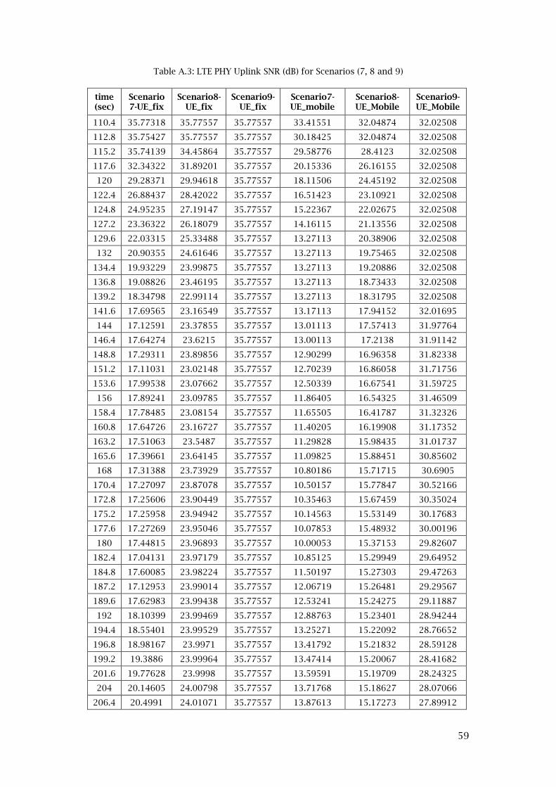
59
Table A.3: LTE PHY Uplink SNR (dB) for Scenarios (7, 8 and 9)
time (sec)
Scenario7-UE_fix
Scenario8-UE_fix
Scenario9-UE_fix
Scenario7-UE_mobile
Scenario8-UE_Mobile
Scenario9-UE_Mobile
110.4 35.77318 35.77557 35.77557 33.41551 32.04874 32.02508
112.8 35.75427 35.77557 35.77557 30.18425 32.04874 32.02508
115.2 35.74139 34.45864 35.77557 29.58776 28.4123 32.02508
117.6 32.34322 31.89201 35.77557 20.15336 26.16155 32.02508
120 29.28371 29.94618 35.77557 18.11506 24.45192 32.02508
122.4 26.88437 28.42022 35.77557 16.51423 23.10921 32.02508
124.8 24.95235 27.19147 35.77557 15.22367 22.02675 32.02508
127.2 23.36322 26.18079 35.77557 14.16115 21.13556 32.02508
129.6 22.03315 25.33488 35.77557 13.27113 20.38906 32.02508
132 20.90355 24.61646 35.77557 13.27113 19.75465 32.02508
134.4 19.93229 23.99875 35.77557 13.27113 19.20886 32.02508
136.8 19.08826 23.46195 35.77557 13.27113 18.73433 32.02508
139.2 18.34798 22.99114 35.77557 13.27113 18.31795 32.02508
141.6 17.69565 23.16549 35.77557 13.17113 17.94152 32.01695
144 17.12591 23.37855 35.77557 13.01113 17.57413 31.97764
146.4 17.64274 23.6215 35.77557 13.00113 17.2138 31.91142
148.8 17.29311 23.89856 35.77557 12.90299 16.96358 31.82338
151.2 17.11031 23.02148 35.77557 12.70239 16.86058 31.71756
153.6 17.99538 23.07662 35.77557 12.50339 16.67541 31.59725
156 17.89241 23.09785 35.77557 11.86405 16.54325 31.46509
158.4 17.78485 23.08154 35.77557 11.65505 16.41787 31.32326
160.8 17.64726 23.16727 35.77557 11.40205 16.19908 31.17352
163.2 17.51063 23.5487 35.77557 11.29828 15.98435 31.01737
165.6 17.39661 23.64145 35.77557 11.09825 15.88451 30.85602
168 17.31388 23.73929 35.77557 10.80186 15.71715 30.6905
170.4 17.27097 23.87078 35.77557 10.50157 15.77847 30.52166
172.8 17.25606 23.90449 35.77557 10.35463 15.67459 30.35024
175.2 17.25958 23.94942 35.77557 10.14563 15.53149 30.17683
177.6 17.27269 23.95046 35.77557 10.07853 15.48932 30.00196
180 17.44815 23.96893 35.77557 10.00053 15.37153 29.82607
182.4 17.04131 23.97179 35.77557 10.85125 15.29949 29.64952
184.8 17.60085 23.98224 35.77557 11.50197 15.27303 29.47263
187.2 17.12953 23.99014 35.77557 12.06719 15.26481 29.29567
189.6 17.62983 23.99438 35.77557 12.53241 15.24275 29.11887
192 18.10399 23.99469 35.77557 12.88763 15.23401 28.94244
194.4 18.55401 23.99529 35.77557 13.25271 15.22092 28.76652
196.8 18.98167 23.9971 35.77557 13.41792 15.21832 28.59128
199.2 19.3886 23.99964 35.77557 13.47414 15.20067 28.41682
201.6 19.77628 23.9998 35.77557 13.59591 15.19709 28.24325
204 20.14605 24.00798 35.77557 13.71768 15.18627 28.07066
206.4 20.4991 24.01071 35.77557 13.87613 15.17273 27.89912

60
208.8 20.83656 24.04393 35.77557 14.03457 15.16897 27.72869
211.2 21.15943 24.0761 35.77557 14.15634 15.15032 27.55943
213.6 21.46864 24.0891 35.77557 14.31478 15.14932 27.39137
216 21.76504 24.09651 35.77557 14.47323 15.13393 27.22455
218.4 22.04941 24.10008 35.77557 14.63168 15.07451 27.05899
220.8 22.32246 24.10022 35.77557 14.79013 15.00651 26.89473
223.2 22.58486 24.10487 35.77557 14.94858 14.91141 26.73177
225.6 22.83722 24.10782 35.77557 15.00002 14.85772 26.57014
228 23.08011 24.10814 35.77557 15.05847 14.70896 26.40983
230.4 23.31405 24.10916 35.77557 15.06695 14.66397 26.25085
232.8 23.53952 24.11282 35.77557 15.1254 14.52531 26.09429
235.2 23.75697 24.13122 35.77557 15.18385 14.4265 25.9431
237.6 23.96683 24.15717 35.77557 15.2423 14.34181 25.79718
240 24.16949 24.15571 35.77557 15.40075 14.25862 25.65627
242.4 24.36531 24.16201 35.77557 15.52251 14.24946 25.52069
244.8 24.55463 24.16243 35.77557 15.64428 14.15438 25.39309
247.2 24.73777 24.34603 35.77557 15.76605 14.36692 25.27357
249.6 24.91503 24.52342 35.77557 15.88781 14.29106 25.16178
252 25.08669 24.69504 35.77557 16.00958 14.12305 25.05742
254.4 25.253 24.86093 35.77557 16.13135 14.06504 24.96021
256.8 25.41422 25.02169 35.77557 16.25312 13.91559 24.86987
259.2 25.57057 25.17714 35.77557 16.37488 13.77472 24.78616
261.6 25.72228 25.32783 35.77557 16.53333 13.64202 24.70884
264 25.86954 25.47377 35.77557 16.69178 13.51679 24.6377
266.4 26.01255 25.61528 35.77557 16.85023 13.41939 24.57252
268.8 26.15148 25.7524 35.77557 17.00868 13.32933 24.51313
271.2 26.28652 25.88547 35.77557 17.16712 13.18586 24.45933
273.6 26.41782 26.01447 35.77557 17.32557 13.08961 24.41097
276 26.54554 26.13963 35.77557 17.48402 13.04118 24.36789
278.4 26.66982 26.26122 35.77557 17.64247 13.03627 24.32995
280.8 26.79079 26.37914 35.77557 17.80092 13.02039 24.297

61
Table A.4: HARQ.UL Retransmission Rate (packets/sec) for Scenarios (1, 2 and 3)
time
(sec)
Scenario
1_UE_fix
Scenario
2-UE_fix
Scenario
3-UE_fix
Scenario1-
UE_mobile
Scenario2-
UE_mobile
Scenario3-
UE_mobile
102.4 0 0 0 0 0 0
104.8 0 0 0 0 0 0
107.2 0 0 0 0 0 0
109.6 0 0 0 0 0 0
112 0 0 0 0 0 0
114.4 0 0 0 0 0 0
116.8 0 0 0 0 0 0
119.2 0 0 0 0 0 0
121.6 0 0 0 0 0 0
124 0 0 0 0 0 0
126.4 0 0 0 0 0 0
128.8 0 0 0 0 0 0
131.2 0 0 0 0 0 0
133.6 0 0 0 0 0 0
136 0 0 0 0 0 0
138.4 0 0 0 0 0 0
140.8 0 0 0 0 0 0
143.2 0 0 0 0 0.3125 0
145.6 0 0 0 0 0.625 0
148 0 0 0 0 6.25 0
150.4 0 0 0 0 11.875 0
152.8 0 0 0 0 16.35416667 0
155.2 0 0 0 0 20.83333333 0
157.6 0 0 0 0 21.66666667 0
160 0 0 0 0 22.5 0
162.4 0 0 0 0.625 41.45833333 0
164.8 0 0 0 1.25 60.41666667 0
167.2 0 0 0 21.66666667 90.20833333 0
169.6 0 0 0 42.08333333 120 0
172 0 0 0 95 122.8125 0
174.4 0 0 0 147.9166667 125.625 0
176.8 0 0 0 159.8958333 145.5208333 0
179.2 0 0 0 171.875 165.4166667 0
181.6 0 0 0 172.0833333 209.5833333 0
184 0 0 0 172.2916667 253.75 0
186.4 0 0 0 181.25 274.375 0
188.8 0 0 0 190.2083333 295 0
191.2 0 0 0 210.4166667 306.0416667 0
193.6 0 0 0 230.625 317.0833333 0
196 0 0 0 256.25 327.7083333 0
198.4 0 0 0 281.875 338.3333333 0
200.8 0 0 0 293.5416667 340.3125 0
203.2 0 0 0 305.2083333 342.2916667 0
205.6 0 0 0 321.4583333 339.1666667 0
208 0 0 0 337.7083333 336.0416667 0
210.4 0 0 0 351.9791667 334.8958333 0
212.8 0 0 0 366.25 333.75 0
215.2 0 0 0 380.3125 333.5416667 0
217.6 0 0 0 394.375 333.3333333 0
220 0 0 0 396.4583333 333.3333333 0

62
222.4 0 0 0 398.5416667 333.3333333 0
224.8 0 0 0 400.9375 333.3333333 0
227.2 0 0 0 403.3333333 333.3333333 0
229.6 0 0 0 404.5833333 333.3333333 0
232 0 0 0 405.8333333 333.3333333 0
234.4 0 0 0 405.3125 333.3333333 0
236.8 0 0 0 404.7916667 333.3333333 0
239.2 0 0 0 405.3125 333.3333333 0
241.6 0 0 0 405.8333333 333.3333333 0
244 0 0 0 404.4791667 333.3333333 0
246.4 0 0 0 403.125 333.3333333 0
248.8 0 0 0 401.3541667 333.3333333 0
251.2 0 0 0 399.5833333 333.3333333 0
253.6 0 0 0 397.2916667 333.3333333 0
256 0 0 0 395 333.3333333 0
258.4 0 0 0 388.3333333 333.5416667 0
260.8 0 0 0 381.6666667 333.75 0
263.2 0 0 0 374.5833333 335 0
265.6 0 0 0 367.5 336.25 0
268 0 0 0 359.1666667 336.1458333 0
270.4 0 0 0 350.8333333 336.0416667 0
272.8 0 0 0 327.6041667 335.3125 0
275.2 0 0 0 304.375 334.5833333 0
277.6 0 0 0 283.75 328.0208333 0
280 0 0 0 263.125 321.4583333 0
282.4 0 0 0 245.8333333 306.4583333 0
284.8 0 0 0 228.5416667 291.4583333 0
287.2 0 0 0 210.2083333 276.0416667 0
289.6 0 0 0 191.875 260.625 0
292 0 0 0 182.5 224.7916667 0
294.4 0 0 0 173.125 188.9583333 0
296.8 0 0 0 172.6041667 160.9375 0
299.2 0 0 0 172.0833333 132.9166667 0
301.6 0 0 0 172.7083333 132.3958333 0
304 0 0 0 173.3333333 131.875 0
306.4 0 0 0 173.6458333 129.5833333 0
308.8 0 0 0 173.9583333 127.2916667 0
311.2 0 0 0 173.9583333 126.5625 0
313.6 0 0 0 173.9583333 125.8333333 0
316 0 0 0 141.1458333 114.6875 0
318.4 0 0 0 108.3333333 103.5416667 0
320.8 0 0 0 60.83333333 66.77083333 0
323.2 0 0 0 13.33333333 30 0
325.6 0 0 0 7.083333333 25.9375 0
328 0 0 0 0.833333333 21.875 0
330.4 0 0 0 0.416666667 20.10416667 0
332.8 0 0 0 0 18.33333333 0
335.2 0 0 0 0 11.04166667 0
337.6 0 0 0 0 3.75 0
340 0 0 0 0 1.875 0
342.4 0 0 0 0 0 0
344.8 0 0 0 0 0 0
347.2 0 0 0 0 0 0
349.6 0 0 0 0 0 0

63
352 0 0 0 0 0 0
354.4 0 0 0 0 0 0
356.8 0 0 0 0 0 0
359.2 0 0 0 0 0 0
361.6 0 0 0 0 0 0
364 0 0 0 0 0 0
366.4 0 0 0 0 0 0
368.8 0 0 0 0 0 0
371.2 0 0 0 0 0 0
373.6 0 0 0 0 0 0
376 0 0 0 0 0 0
378.4 0 0 0 0 0 0
380.8 0 0 0 0 0 0
383.2 0 0 0 0 0 0
385.6 0 0 0 0 0 0
388 0 0 0 0 0 0
390.4 0 0 0 0 0 0
392.8 0 0 0 0 0 0
395.2 0 0 0 0 0 0
397.6 0 0 0 0 0 0
400 0 0 0 0 0 0
402.4 0 0 0 0 0 0
404.8 0 0 0 0 0 0
407.2 0 0 0 0 0 0
409.6 0 0 0 0 0 0
412 0 0 0 0 0 0
414.4 0 0 0 0 0 0
416.8 0 0 0 0 0 0
419.2 0 0 0 0 0 0
421.6 0 0 0 0 0 0
424 0 0 0 0 0 0
426.4 0 0 0 0 0 0
428.8 0 0 0 0 0 0
431.2 0 0 0 0 0 0
433.6 0 0 0 0 0 0
436 0 0 0 0 0 0
438.4 0 0 0 0 0 0
440.8 0 0 0 0 0 0
443.2 0 0 0 0 0 0
445.6 0 0 0 0 0 0
448 0 0 0 0 0 0
450.4 0 0 0 0 0 0
452.8 0 0 0 0 0 0
455.2 0 0 0 0 0 0
457.6 0 0 0 0 0 0
460 0 0 0 0 0 0
462.4 0 0 0 0 0 0
464.8 0 0 0 0 0 0
467.2 0 0 0 0 0 0
469.6 0 0 0 0 0 0
472 0 0 0 0 0 0
474.4 0 0 0 0 0 0
476.8 0 0 0 0 0 0
479.2 0 0 0 0 0 0

64
Table A.5: HARQ.UL Retransmission Rate (packets/sec) for Scenarios (4, 5 and 6)
time
(sec)
Scenario
4-UE_fix
Scenario5-
UE_fix
Scenario6-
UE_fix
Scenario4-
UE_mobile
Scenario5-
UE_Mobile
Scenario6-
UE_Mobile
102.4 0 0 0 0 0 0
104.8 0 0 0 0 0 0
107.2 0 0 0 0 0 0
109.6 0 0 0 0 0 0
112 0 0 0 0 0 0
114.4 0 0 0 0 0 0
116.8 0 0 0 0 0 0
119.2 0 0 0 0 0 0
121.6 0 0 0 0 0 0
124 0 0 0 0 0 0
126.4 0 0 0 0 0 0
128.8 0 0 0 0 0 0
131.2 0 0 0 0 0 0
133.6 0 0 0 0 0 0
136 0 0 0 0 0 0
138.4 0 0 0 0 0 0
140.8 0 0 0 0 0 0
143.2 0 0 0 0 0.104166667 0
145.6 0 0 0 0 0.208333333 0
148 0 0 0 0 4.791666667 0
150.4 0 0 0 0 9.375 0
152.8 0 0 0 0 13.4375 0
155.2 0 0 0 0 17.5 0
157.6 0 0 0 0 20.3125 0
160 0 0 0 0 23.125 0
162.4 0 0 0 1.979166667 90.72916667 0
164.8 0 0 0 3.958333333 158.3333333 0
167.2 0 0 0 35.3125 241.875 0
169.6 0 0 0 66.66666667 325.4166667 0
172 0 0 0 186.9791667 328.8541667 0
174.4 0 0 0 307.2916667 332.2916667 0
176.8 0 0 0 342.5 350.4166667 0
179.2 0 0 0 377.7083333 368.5416667 0
181.6 0 0 0 380.7291667 400.1041667 0
184 0 0 0 383.75 431.6666667 0
186.4 0 0 0 390.625 454.6875 0
188.8 0 0 0 397.5 477.7083333 0
191.2 0 0 0 421.4583333 481.5625 0
193.6 0 0 0 445.4166667 485.4166667 0
196 0 0 0 463.6458333 487.7083333 0
198.4 0 0 0 481.875 490 0

65
200.8 0 0 0 488.6458333 490.1041667 0
203.2 0 0 0 495.4166667 490.2083333 0
205.6 0 0 0 504.4791667 490.1041667 0
208 0 0 0 513.5416667 490 0
210.4 0 0 0 520.5208333 490 0
212.8 0 0 0 527.5 490 0
215.2 0 0 0 530.3125 490 0
217.6 0 0 0 533.125 490 0
220 0 0 0 534.6875 490 0
222.4 0 0 0 536.25 490 0
224.8 0 0 0 537.7083333 490 0
227.2 0 0 0 539.1666667 490 0
229.6 0 0 0 539.1666667 490 0
232 0 0 0 539.1666667 490 0
234.4 0 0 0 539.1666667 490 0
236.8 0 0 0 539.1666667 490 0
239.2 0 0 0 539.1666667 490 0
241.6 0 0 0 539.1666667 490 0
244 0 0 0 538.9583333 490 0
246.4 0 0 0 538.75 490 0
248.8 0 0 0 537.0833333 490 0
251.2 0 0 0 535.4166667 490 0
253.6 0 0 0 533.75 490 0
256 0 0 0 532.0833333 490 0
258.4 0 0 0 529.6875 490 0
260.8 0 0 0 527.2916667 490 0
263.2 0 0 0 523.125 490 0
265.6 0 0 0 518.9583333 490 0
268 0 0 0 509.7916667 489.8958333 0
270.4 0 0 0 500.625 489.7916667 0
272.8 0 0 0 495.5208333 488.8541667 0
275.2 0 0 0 490.4166667 487.9166667 0
277.6 0 0 0 484.5833333 486.875 0
280 0 0 0 478.75 485.8333333 0
282.4 0 0 0 458.9583333 483.3333333 0
284.8 0 0 0 439.1666667 480.8333333 0
287.2 0 0 0 418.6458333 465.9375 0
289.6 0 0 0 398.125 451.0416667 0
292 0 0 0 392.5 419.7916667 0
294.4 0 0 0 386.875 388.5416667 0
296.8 0 0 0 383.8541667 364.2708333 0
299.2 0 0 0 380.8333333 340 0
301.6 0 0 0 380.1041667 335.7291667 0
304 0 0 0 379.375 331.4583333 0

66
306.4 0 0 0 379.6875 330.7291667 0
308.8 0 0 0 380 330 0
311.2 0 0 0 373.4375 329.0625 0
313.6 0 0 0 366.875 328.125 0
316 0 0 0 291.6666667 308.125 0
318.4 0 0 0 216.4583333 288.125 0
320.8 0 0 0 122.5 174.7916667 0
323.2 0 0 0 28.54166667 61.45833333 0
325.6 0 0 0 14.79166667 31.35416667 0
328 0 0 0 1.041666667 1.25 0
330.4 0 0 0 0.520833333 0.625 0
332.8 0 0 0 0 0 0
335.2 0 0 0 0 0 0
337.6 0 0 0 0 0 0
340 0 0 0 0 0 0
342.4 0 0 0 0 0 0
344.8 0 0 0 0 0 0
347.2 0 0 0 0 0 0
349.6 0 0 0 0 0 0
352 0 0 0 0 0 0
354.4 0 0 0 0 0 0
356.8 0 0 0 0 0 0
359.2 0 0 0 0 0 0
361.6 0 0 0 0 0 0
364 0 0 0 0 0 0
366.4 0 0 0 0 0 0
368.8 0 0 0 0 0 0
371.2 0 0 0 0 0 0
373.6 0 0 0 0 0 0
376 0 0 0 0 0 0
378.4 0 0 0 0 0 0
380.8 0 0 0 0 0 0
383.2 0 0 0 0 0 0
385.6 0 0 0 0 0 0
388 0 0 0 0 0 0
390.4 0 0 0 0 0 0
392.8 0 0 0 0 0 0
395.2 0 0 0 0 0 0
397.6 0 0 0 0 0 0
400 0 0 0 0 0 0
402.4 0 0 0 0 0 0
404.8 0 0 0 0 0 0
407.2 0 0 0 0 0 0
409.6 0 0 0 0 0 0

67
412 0 0 0 0 0 0
414.4 0 0 0 0 0 0
416.8 0 0 0 0 0 0
419.2 0 0 0 0 0 0
421.6 0 0 0 0 0 0
424 0 0 0 0 0 0
426.4 0 0 0 0 0 0
428.8 0 0 0 0 0 0
431.2 0 0 0 0 0 0
433.6 0 0 0 0 0 0
436 0 0 0 0 0 0
438.4 0 0 0 0 0 0
440.8 0 0 0 0 0 0
443.2 0 0 0 0 0 0
445.6 0 0 0 0 0 0
448 0 0 0 0 0 0
450.4 0 0 0 0 0 0
452.8 0 0 0 0 0 0
455.2 0 0 0 0 0 0
457.6 0 0 0 0 0 0
460 0 0 0 0 0 0
462.4 0 0 0 0 0 0
464.8 0 0 0 0 0 0
467.2 0 0 0 0 0 0
469.6 0 0 0 0 0 0
472 0 0 0 0 0 0
474.4 0 0 0 0 0 0
476.8 0 0 0 0 0 0
479.2 0 0 0 0 0 0

68
Table A.6: HARQ.UL Retransmission Rate (packets/sec) for Scenarios (7, 8 and 9)
time
(sec)
Scenario
7-UE_fix
Scenario8-
UE_fix
Scenario9-
UE_fix
Scenario7-
UE_mobile
Scenario8-
UE_Mobile
Scenario9-
UE_Mobile
102.4 0 0 0 0 0 0
104.8 0 0 0 0 0 0
107.2 0 0 0 0 0 0
109.6 0 0 0 0 0 0
112 0 0 0 0 0 0
114.4 0 0 0 0 0 0
116.8 0 0 0 0 0 0
119.2 0 0 0 0 0 0
121.6 0 0 0 0 0 0
124 0 0 0 0 0 0
126.4 0 0 0 0 0 0
128.8 0 0 0 0 0 0
131.2 0 0 0 0 0 0
133.6 0 0 0 0 0 0
136 0 0 0 0 0 0
138.4 0 0 0 0.104167 0 0
140.8 0 0 0 0.208333 0 0
143.2 0 0 0 51.875 0 0
145.6 0 0 0 103.5417 0 0
148 0 0 0 245.8333 0 0
150.4 0 0 0 388.125 0 0
152.8 0 0 0 400.8333 0.104166667 0
155.2 0 0 0 413.5417 0.208333333 0
157.6 0 0 0 461.3542 4.0625 0
160 0 0 0 509.1667 7.916666667 0
162.4 0 0 0 551.3542 97.70833333 0
164.8 0 0 0 593.5417 187.5 0
167.2 0 0 0 596.7708 289.8958333 0
169.6 0 0 0 600 392.2916667 0
172 0 0 0 600.1042 398.6458333 0
174.4 0 0 0 600.2083 405 0
176.8 0 0 0 460.3125 417.7083333 0
179.2 0 0 0 320.4167 430.4166667 0
181.6 0 0 0 160.2083 466.7708333 0
184 0 0 0 0 503.125 0
186.4 0 0 0 0 520.8333333 0
188.8 0 0 0 0 538.5416667 0
191.2 0 0 0 0 550.9375 0
193.6 0 0 0 0 563.3333333 0
196 0 0 0 0 576.9791667 0
198.4 0 0 0 0 590.625 0

69
200.8 0 0 0 0 595.3125 0
203.2 0 0 0 0 600 0
205.6 0 0 0 0 351.7708333 0
208 0 0 0 0 103.5416667 0
210.4 0 0 0 0 51.77083333 0
212.8 0 0 0 0 0 0
215.2 0 0 0 0 0 0
217.6 0 0 0 0 0 0
220 0 0 0 0 0 0
222.4 0 0 0 0 0 0
224.8 0 0 0 0 0 0
227.2 0 0 0 0 0 0
229.6 0 0 0 0 0 0
232 0 0 0 0 0 0
234.4 0 0 0 0 0 0
236.8 0 0 0 0 0 0
239.2 0 0 0 0 0 0
241.6 0 0 0 0 0 0
244 0 0 0 0 0 0
246.4 0 0 0 0 0 0
248.8 0 0 0 0 0 0
251.2 0 0 0 0 0 0
253.6 0 0 0 0 0 0
256 0 0 0 0 0 0
258.4 0 0 0 0 0 0
260.8 0 0 0 0 0 0
263.2 0 0 0 0 0 0
265.6 0 0 0 0 0 0
268 0 0 0 0 0 0
270.4 0 0 0 0 0 0
272.8 0 0 0 0 0 0
275.2 0 0 0 0 0 0
277.6 0 0 0 0 0 0
280 0 0 0 0 0 0
282.4 0 0 0 0 0 0
284.8 0 0 0 0 0 0
287.2 0 0 0 0 0 0
289.6 0 0 0 0 0 0
292 0 0 0 0 0 0
294.4 0 0 0 0 0 0
296.8 0 0 0 0 0 0
299.2 0 0 0 0 0 0
301.6 0 0 0 0 0 0
304 0 0 0 0 0 0

70
306.4 0 0 0 0 0 0
308.8 0 0 0 0 0 0
311.2 0 0 0 0 0 0
313.6 0 0 0 0 0 0
316 0 0 0 0 0 0
318.4 0 0 0 0 0 0
320.8 0 0 0 0 0 0
323.2 0 0 0 0 0 0
325.6 0 0 0 0 0 0
328 0 0 0 0 0 0
330.4 0 0 0 0 0.3125 0
332.8 0 0 0 0 0.625 0
335.2 0 0 0 0 0.3125 0
337.6 0 0 0 0 0 0
340 0 0 0 0 0 0
342.4 0 0 0 0 0 0
344.8 0 0 0 0 0 0
347.2 0 0 0 0 0 0
349.6 0 0 0 0 0 0
352 0 0 0 0 0 0
354.4 0 0 0 0 0 0
356.8 0 0 0 0 0 0
359.2 0 0 0 0 0 0
361.6 0 0 0 0 0 0
364 0 0 0 0 0 0
366.4 0 0 0 0 0 0
368.8 0 0 0 0 0 0
371.2 0 0 0 0 0 0
373.6 0 0 0 0 0 0
376 0 0 0 0 0 0
378.4 0 0 0 0 0 0
380.8 0 0 0 0 0 0
383.2 0 0 0 0 0 0
385.6 0 0 0 0 0 0
388 0 0 0 0 0 0
390.4 0 0 0 0 0 0
392.8 0 0 0 0 0 0
395.2 0 0 0 0 0 0
397.6 0 0 0 0 0 0
400 0 0 0 0 0 0
402.4 0 0 0 0 0 0
404.8 0 0 0 0 0 0
407.2 0 0 0 0 0 0
409.6 0 0 0 0 0 0

71
412 0 0 0 0 0 0
414.4 0 0 0 0 0 0
416.8 0 0 0 0 0 0
419.2 0 0 0 0 0 0
421.6 0 0 0 0 0 0
424 0 0 0 0 0 0
426.4 0 0 0 0 0 0
428.8 0 0 0 0 0 0
431.2 0 0 0 0 0 0
433.6 0 0 0 0 0 0
436 0 0 0 0 0 0
438.4 0 0 0 0 0 0
440.8 0 0 0 0 0 0
443.2 0 0 0 0 0 0
445.6 0 0 0 0 0 0
448 0 0 0 0 0 0
450.4 0 0 0 0 0 0
452.8 0 0 0 0 0 0
455.2 0 0 0 0 0 0
457.6 0 0 0 0 0 0
460 0 0 0 0 0 0
462.4 0 0 0 0 0 0
464.8 0 0 0 0 0 0
467.2 0 0 0 0 0 0
469.6 0 0 0 0 0 0
472 0 0 0 0 0 0
474.4 0 0 0 0 0 0
476.8 0 0 0 0 0 0
479.2 0 0 0 0 0 0
479.2 0 0 0 0 0 0

72
Table A.7: Packet End-to-End Delay (sec) for Scenarios (1, 2 and 3)
time
(sec)
Scenario1
_UE_fix
Scenario2-
UE_fix
Scenario3-
UE_fix
Scenario1-
UE_mobile
Scenario2-
UE_mobile
Scenario3-
UE_mobile
102.4 #N/A #N/A #N/A #N/A #N/A #N/A
104.8 #N/A #N/A #N/A #N/A #N/A #N/A
107.2 #N/A #N/A #N/A #N/A #N/A #N/A
109.6 #N/A #N/A #N/A #N/A #N/A #N/A
112 0.045895 0.045896 0.045896 #N/A 0.045898 0.045898
114.4 0.045895 0.045896 0.045896 #N/A 0.045898 0.045898
116.8 0.045895 0.045896 0.045896 0.045897 0.045898 0.045898
119.2 0.045895 0.045896 0.045896 0.045897 0.045898 0.045898
121.6 0.045895 0.045896 0.045896 0.045897 0.045898 0.045898
124 0.045895 0.045896 0.045896 0.045897 0.045898 0.045898
126.4 0.045895 0.045896 0.045896 0.045897 0.045898 0.045898
128.8 0.045895 0.045896 0.045896 0.045897 0.045898 0.045898
131.2 0.045895 0.045896 0.045896 0.045897 0.045898 0.045898
133.6 0.045895 0.045896 0.045896 0.045897 0.045898 0.045898
136 0.045895 0.045896 0.045896 0.045897 0.045898 0.045898
138.4 0.045895 0.045896 0.045896 0.045897 0.045898 0.045898
140.8 0.045895 0.045896 0.045896 0.045897 0.045898 0.045898
143.2 0.045895 0.045896 0.045896 0.045897 0.045898 0.045898
145.6 0.045895 0.045896 0.045896 0.045897 0.045898 0.045898
148 0.045895 0.045896 0.045896 0.045918 0.045898 0.045898
150.4 0.045895 0.045896 0.045896 0.045939 0.045898 0.045898
152.8 0.045895 0.045896 0.045896 0.045949 0.045898 0.045898
155.2 0.045895 0.045896 0.045896 0.04596 0.045898 0.045898
157.6 0.045895 0.045896 0.045896 0.046824 0.045898 0.045898
160 0.045895 0.045896 0.045896 0.047689 0.045898 0.045898
162.4 0.045895 0.045896 0.045896 0.051272 0.046002 0.045898
164.8 0.045895 0.045896 0.045896 0.054856 0.046106 0.045898
167.2 0.045895 0.045896 0.045896 0.058606 0.046189 0.045898
169.6 0.045895 0.045896 0.045896 0.062356 0.046273 0.045898
172 0.045895 0.045896 0.045896 0.064324 0.046262 0.045898
174.4 0.045895 0.045896 0.045896 0.066293 0.046252 0.045898
176.8 0.045895 0.045896 0.045896 0.067366 0.046543 0.045898
179.2 0.045895 0.045896 0.045896 0.068439 0.046835 0.045898
181.6 0.045895 0.045896 0.045896 0.068554 0.0477 0.045898
184 0.045895 0.045896 0.045896 0.068668 0.048564 0.045898
186.4 0.045895 0.045896 0.045896 0.068856 0.048804 0.045898
188.8 0.045895 0.045896 0.045896 0.069043 0.049043 0.045898
191.2 0.045895 0.045896 0.045896 0.068856 0.049064 0.045898
193.6 0.045895 0.045896 0.045896 0.068668 0.049085 0.045898
196 0.045895 0.045896 0.045896 0.069002 0.048908 0.045898
198.4 0.045895 0.045896 0.045896 0.069335 0.048731 0.045898

73
200.8 0.045895 0.045896 0.045896 0.069762 0.048668 0.045898
203.2 0.045895 0.045896 0.045896 0.070189 0.048606 0.045898
205.6 0.045895 0.045896 0.045896 0.070429 0.048502 0.045898
208 0.045895 0.045896 0.045896 0.070668 0.048398 0.045898
210.4 0.045895 0.045896 0.045896 0.071043 0.048366 0.045898
212.8 0.045895 0.045896 0.045896 0.071418 0.048335 0.045898
215.2 0.045895 0.045896 0.045896 0.07171 0.048325 0.045898
217.6 0.045895 0.045896 0.045896 0.072002 0.048314 0.045898
220 0.045895 0.045896 0.045896 0.071845 0.048314 0.045898
222.4 0.045895 0.045896 0.045896 0.071689 0.048314 0.045898
224.8 0.045895 0.045896 0.045896 0.071595 0.048314 0.045898
227.2 0.045895 0.045896 0.045896 0.071502 0.048314 0.045898
229.6 0.045895 0.045896 0.045896 0.071543 0.048314 0.045898
232 0.045895 0.045896 0.045896 0.071585 0.048314 0.045898
234.4 0.045895 0.045896 0.045896 0.071668 0.048314 0.045898
236.8 0.045895 0.045896 0.045896 0.071752 0.048314 0.045898
239.2 0.045895 0.045896 0.045896 0.071731 0.048314 0.045898
241.6 0.045895 0.045896 0.045896 0.07171 0.048314 0.045898
244 0.045895 0.045896 0.045896 0.071752 0.048314 0.045898
246.4 0.045895 0.045896 0.045896 0.071793 0.048314 0.045898
248.8 0.045895 0.045896 0.045896 0.071929 0.048314 0.045898
251.2 0.045895 0.045896 0.045896 0.072064 0.048314 0.045898
253.6 0.045895 0.045896 0.045896 0.072116 0.048314 0.045898
256 0.045895 0.045896 0.045896 0.072168 0.048314 0.045898
258.4 0.045895 0.045896 0.045896 0.072252 0.048325 0.045898
260.8 0.045895 0.045896 0.045896 0.072335 0.048335 0.045898
263.2 0.045895 0.045896 0.045896 0.072241 0.048356 0.045898
265.6 0.045895 0.045896 0.045896 0.072147 0.048377 0.045898
268 0.045895 0.045896 0.045896 0.071814 0.04846 0.045898
270.4 0.045895 0.045896 0.045896 0.071481 0.048543 0.045898
272.8 0.045895 0.045896 0.045896 0.070752 0.048627 0.045898
275.2 0.045895 0.045896 0.045896 0.070022 0.04871 0.045898
277.6 0.045895 0.045896 0.045896 0.070033 0.04895 0.045898
280 0.045895 0.045896 0.045896 0.070043 0.049189 0.045898
282.4 0.045895 0.045896 0.045896 0.070262 0.049075 0.045898
284.8 0.045895 0.045896 0.045896 0.070481 0.04896 0.045898
287.2 0.045895 0.045896 0.045896 0.070647 0.048752 0.045898
289.6 0.045895 0.045896 0.045896 0.070814 0.048543 0.045898
292 0.045895 0.045896 0.045896 0.071012 0.04795 0.045898
294.4 0.045895 0.045896 0.045896 0.07121 0.047356 0.045898
296.8 0.045895 0.045896 0.045896 0.071408 0.046877 0.045898
299.2 0.045895 0.045896 0.045896 0.071606 0.046398 0.045898
301.6 0.045895 0.045896 0.045896 0.071866 0.046314 0.045898
304 0.045895 0.045896 0.045896 0.072127 0.046231 0.045898

74
306.4 0.045895 0.045896 0.045896 0.072252 0.046252 0.045898
308.8 0.045895 0.045896 0.045896 0.072377 0.046273 0.045898
311.2 0.045895 0.045896 0.045896 0.071762 0.046283 0.045898
313.6 0.045895 0.045896 0.045896 0.071147 0.046293 0.045898
316 0.045895 0.045896 0.045896 0.070043 0.046179 0.045898
318.4 0.045895 0.045896 0.045896 0.068939 0.046064 0.045898
320.8 0.045895 0.045896 0.045896 0.067668 0.046002 0.045898
323.2 0.045895 0.045896 0.045896 0.066397 0.045939 0.045898
325.6 0.045895 0.045896 0.045896 0.066147 0.045918 0.045898
328 0.045895 0.045896 0.045896 0.065897 0.045898 0.045898
330.4 0.045895 0.045896 0.045896 0.065606 0.045898 0.045898
332.8 0.045895 0.045896 0.045896 0.065314 0.045898 0.045898
335.2 0.045895 0.045896 0.045896 0.065147 0.045898 0.045898
337.6 0.045895 0.045896 0.045896 0.064981 0.045898 0.045898
340 0.045895 0.045896 0.045896 0.063887 0.045898 0.045898
342.4 0.045895 0.045896 0.045896 0.062793 0.045898 0.045898
344.8 0.045895 0.045896 0.045896 0.056897 0.045898 0.045898
347.2 0.045895 0.045896 0.045896 0.051002 0.045898 0.045898
349.6 0.045895 0.045896 0.045896 0.048512 0.045898 0.045898
352 0.045895 0.045896 0.045896 0.046022 0.045898 0.045898
354.4 0.045895 0.045896 0.045896 0.04597 0.045898 0.045898
356.8 0.045895 0.045896 0.045896 0.045918 0.045898 0.045898
359.2 0.045895 0.045896 0.045896 0.045918 0.045898 0.045898
361.6 0.045895 0.045896 0.045896 0.045918 0.045898 0.045898
364 0.045895 0.045896 0.045896 0.045949 0.045898 0.045898
366.4 0.045895 0.045896 0.045896 0.045981 0.045898 0.045898
368.8 0.045895 0.045896 0.045896 0.045949 0.045898 0.045898
371.2 0.045895 0.045896 0.045896 0.045918 0.045898 0.045898
373.6 0.045895 0.045896 0.045896 0.045908 0.045898 0.045898
376 0.045895 0.045896 0.045896 0.045897 0.045898 0.045898
378.4 0.045895 0.045896 0.045896 0.045897 0.045898 0.045898
380.8 0.045895 0.045896 0.045896 0.045897 0.045898 0.045898
383.2 0.045895 0.045896 0.045896 0.045908 0.045898 0.045898
385.6 0.045895 0.045896 0.045896 0.045918 0.045898 0.045898
388 0.045895 0.045896 0.045896 0.045939 0.045898 0.045898
390.4 0.045895 0.045896 0.045896 0.04596 0.045898 0.045898
392.8 0.045895 0.045896 0.045896 0.045949 0.045898 0.045898
395.2 0.045895 0.045896 0.045896 0.045939 0.045898 0.045898
397.6 0.045895 0.045896 0.045896 0.045929 0.045898 0.045898
400 0.045895 0.045896 0.045896 0.045918 0.045898 0.045898
402.4 0.045895 0.045896 0.045896 0.045918 0.045898 0.045898
404.8 0.045895 0.045896 0.045896 0.045918 0.045898 0.045898
407.2 0.045895 0.045896 0.045896 0.04596 0.045898 0.045898
409.6 0.045895 0.045896 0.045896 0.046002 0.045898 0.045898

75
412 0.045895 0.045896 0.045896 0.045949 0.045898 0.045898
414.4 0.045895 0.045896 0.045896 0.045897 0.045898 0.045898
416.8 0.045895 0.045896 0.045896 0.045897 0.045898 0.045898
419.2 0.045895 0.045896 0.045896 0.045897 0.045898 0.045898
421.6 0.045895 0.045896 0.045896 0.045897 0.045898 0.045898
424 0.045895 0.045896 0.045896 0.045897 0.045898 0.045898
426.4 0.045895 0.045896 0.045896 0.045897 0.045898 0.045898
428.8 0.045895 0.045896 0.045896 0.045897 0.045898 0.045898
431.2 0.045895 0.045896 0.045896 0.045918 0.045898 0.045898
433.6 0.045895 0.045896 0.045896 0.045939 0.045898 0.045898
436 0.045895 0.045896 0.045896 0.045918 0.045898 0.045898
438.4 0.045895 0.045896 0.045896 0.045897 0.045898 0.045898
440.8 0.045895 0.045896 0.045896 0.045897 0.045898 0.045898
443.2 0.045895 0.045896 0.045896 0.045897 0.045898 0.045898
445.6 0.045895 0.045896 0.045896 0.045908 0.045898 0.045898
448 0.045895 0.045896 0.045896 0.045918 0.045898 0.045898
450.4 0.045895 0.045896 0.045896 0.045908 0.045898 0.045898
452.8 0.045895 0.045896 0.045896 0.045897 0.045898 0.045898
455.2 0.045895 0.045896 0.045896 0.045897 0.045898 0.045898
457.6 0.045895 0.045896 0.045896 0.045897 0.045898 0.045898
460 0.045895 0.045896 0.045896 0.045918 0.045898 0.045898
462.4 0.045895 0.045896 0.045896 0.045939 0.045898 0.045898
464.8 0.045895 0.045896 0.045896 0.045929 0.045898 0.045898
467.2 0.045895 0.045896 0.045896 0.045918 0.045898 0.045898
469.6 0.045895 0.045896 0.045896 0.045908 0.045898 0.045898
472 0.045895 0.045896 0.045896 0.045897 0.045898 0.045898
474.4 0.045895 0.045896 0.045896 0.045918 0.045898 0.045898
476.8 0.045895 0.045896 0.045896 0.045939 0.045898 0.045898
479.2 0.045895 0.045896 0.045896 0.045939 0.045898 0.045898
479.2 #N/A1 #N/A #N/A #N/A #N/A #N/A
1 #N/A denotes that the value is same as the previous value in the column and it remains same for the consecutive #N/A.

76
Table A.8: Packet End-to-End Delay (sec) for Scenarios (4, 5 and 6)
time
(sec)
Scenario
4-UE_fix
Scenario5-
UE_fix
Scenario6-
UE_fix
Scenario4-
UE_mobile
Scenario5-
UE_Mobile
Scenario6-
UE_Mobile
102.4 #N/A 0 #N/A #N/A 0 #N/A
104.8 #N/A 0 #N/A #N/A 0 #N/A
107.2 #N/A 0 #N/A #N/A 0 #N/A
109.6 #N/A 0.203964 #N/A #N/A 0.202574 #N/A
112 0.066895 0.407929 0.066896 #N/A 0.405149 0.066898
114.4 0.066895 0.538446 0.066896 #N/A 0.537062 0.066898
116.8 0.066895 0.668964 0.066896 0.066897 0.668976 0.066898
119.2 0.066895 0.668964 0.066896 0.066897 0.668976 0.066898
121.6 0.066895 0.668964 0.066896 0.066897 0.668976 0.066898
124 0.066895 0.668964 0.066896 0.066897 0.668976 0.066898
126.4 0.066895 0.668964 0.066896 0.066897 0.668976 0.066898
128.8 0.066895 0.668964 0.066896 0.066897 0.668976 0.066898
131.2 0.066895 0.668964 0.066896 0.066897 0.668976 0.066898
133.6 0.066895 0.668964 0.066896 0.066897 0.668976 0.066898
136 0.066895 0.668964 0.066896 0.066897 0.668976 0.066898
138.4 0.066895 0.668964 0.066896 0.066897 0.668976 0.066898
140.8 0.066895 0.668964 0.066896 0.066897 0.668976 0.066898
143.2 0.066895 0.668964 0.066896 0.066897 0.668976 0.066898
145.6 0.066895 0.668964 0.066896 0.066897 0.668976 0.066898
148 0.066895 0.668964 0.066896 0.066897 0.668976 0.066898
150.4 0.066895 0.668964 0.066896 0.066897 0.668976 0.066898
152.8 0.066895 0.668964 0.066896 0.066929 0.668976 0.066898
155.2 0.066895 0.668964 0.066896 0.06696 0.668976 0.066898
157.6 0.066895 0.668964 0.066896 0.068439 0.669646 0.066898
160 0.066895 0.668964 0.066896 0.069918 0.670316 0.066898
162.4 0.066895 0.668964 0.066896 0.075835 0.68328 0.066898
164.8 0.066895 0.668964 0.066896 0.081752 0.696243 0.066898
167.2 0.066895 0.668964 0.066896 0.09191 0.705748 0.066898
169.6 0.066895 0.668964 0.066896 0.102068 0.715252 0.066898
172 0.066895 0.668964 0.066896 0.171771 0.714157 0.066898
174.4 0.066895 0.668964 0.066896 0.241475 0.713063 0.066898
176.8 0.066895 0.668964 0.066896 0.4665 0.723437 0.066898
179.2 0.066895 0.668964 0.066896 0.691525 0.733811 0.066898
181.6 0.066895 0.668964 0.066896 0.985926 0.75142 0.066898
184 0.066895 0.668964 0.066896 1.280326 0.769028 0.066898
186.4 0.066895 0.668964 0.066896 1.585409 0.779857 0.066898
188.8 0.066895 0.668964 0.066896 1.890493 0.790686 0.066898
191.2 0.066895 0.668964 0.066896 2.17029 0.78956 0.066898
193.6 0.066895 0.668964 0.066896 2.450088 0.788433 0.066898
196 0.066895 0.668964 0.066896 2.735862 0.776354 0.066898
198.4 0.066895 0.668964 0.066896 3.021635 0.764275 0.066898

77
200.8 0.066895 0.668964 0.066896 3.371705 0.758605 0.066898
203.2 0.066895 0.668964 0.066896 3.721775 0.752934 0.066898
205.6 0.066895 0.668964 0.066896 4.130452 0.75408 0.066898
208 0.066895 0.668964 0.066896 4.539128 0.755226 0.066898
210.4 0.066895 0.668964 0.066896 5.020202 0.756288 0.066898
212.8 0.066895 0.668964 0.066896 5.501276 0.75735 0.066898
215.2 0.066895 0.668964 0.066896 6.03987 0.757526 0.066898
217.6 0.066895 0.668964 0.066896 6.578465 0.757703 0.066898
220 0.066895 0.668964 0.066896 7.174112 0.761408 0.066898
222.4 0.066895 0.668964 0.066896 7.769759 0.765114 0.066898
224.8 0.066895 0.668964 0.066896 8.407614 0.7682 0.066898
227.2 0.066895 0.668964 0.066896 9.045469 0.771286 0.066898
229.6 0.066895 0.668964 0.066896 9.702139 0.769063 0.066898
232 0.066895 0.668964 0.066896 10.35881 0.766841 0.066898
234.4 0.066895 0.668964 0.066896 11.03188 0.766426 0.066898
236.8 0.066895 0.668964 0.066896 11.70495 0.766011 0.066898
239.2 0.066895 0.668964 0.066896 12.3781 0.766355 0.066898
241.6 0.066895 0.668964 0.066896 13.05124 0.766699 0.066898
244 0.066895 0.668964 0.066896 13.72095 0.772004 0.066898
246.4 0.066895 0.668964 0.066896 14.39066 0.777309 0.066898
248.8 0.066895 0.668964 0.066896 15.07844 0.777477 0.066898
251.2 0.066895 0.668964 0.066896 15.76622 0.777646 0.066898
253.6 0.066895 0.668964 0.066896 16.46868 0.786265 0.066898
256 0.066895 0.668964 0.066896 17.17113 0.794885 0.066898
258.4 0.066895 0.668964 0.066896 17.86346 0.808013 0.066898
260.8 0.066895 0.668964 0.066896 18.55578 0.82114 0.066898
263.2 0.066895 0.668964 0.066896 19.24763 0.834759 0.066898
265.6 0.066895 0.668964 0.066896 19.93949 0.848378 0.066898
268 0.066895 0.668964 0.066896 20.38542 0.872849 0.066898
270.4 0.066895 0.668964 0.066896 20.83136 0.89732 0.066898
272.8 0.066895 0.668964 0.066896 20.83136 0.915898 0.066898
275.2 0.066895 0.668964 0.066896 #N/A 0.934476 0.066898
277.6 0.066895 0.668964 0.066896 20.83136 0.972046 0.066898
280 0.066895 0.668964 0.066896 #N/A 1.009616 0.066898
282.4 0.066895 0.668964 0.066896 20.83136 1.055557 0.066898
284.8 0.066895 0.668964 0.066896 #N/A 1.101498 0.066898
287.2 0.066895 0.668964 0.066896 20.83136 1.244925 0.066898
289.6 0.066895 0.668964 0.066896 #N/A 1.388353 0.066898
292 0.066895 0.668964 0.066896 20.83136 1.949467 0.066898
294.4 0.066895 0.668964 0.066896 #N/A 2.510582 0.066898
296.8 0.066895 0.668964 0.066896 20.83136 3.325343 0.066898
299.2 0.066895 0.668964 0.066896 #N/A 4.140105 0.066898
301.6 0.066895 0.668964 0.066896 20.83136 4.937515 0.066898
304 0.066895 0.668964 0.066896 #N/A 5.734926 0.066898

78
306.4 0.066895 0.668964 0.066896 20.83136 6.503678 0.066898
308.8 0.066895 0.668964 0.066896 #N/A 7.272429 0.066898
311.2 0.066895 0.668964 0.066896 20.83136 7.965163 0.066898
313.6 0.066895 0.668964 0.066896 #N/A 8.657897 0.066898
316 0.066895 0.668964 0.066896 20.83136 9.274077 0.066898
318.4 0.066895 0.668964 0.066896 #N/A 9.890257 0.066898
320.8 0.066895 0.668964 0.066896 20.83136 9.961574 0.066898
323.2 0.066895 0.668964 0.066896 #N/A 10.03289 0.066898
325.6 0.066895 0.668964 0.066896 20.83136 7.943333 0.066898
328 0.066895 0.668964 0.066896 #N/A 5.853775 0.066898
330.4 0.066895 0.668964 0.066896 20.83136 3.312866 0.066898
332.8 0.066895 0.668964 0.066896 #N/A 0.771957 0.066898
335.2 0.066895 0.668964 0.066896 20.83136 0.726833 0.066898
337.6 0.066895 0.668964 0.066896 #N/A 0.681708 0.066898
340 0.066895 0.668964 0.066896 20.83136 0.675609 0.066898
342.4 0.066895 0.668964 0.066896 #N/A 0.669511 0.066898
344.8 0.066895 0.668964 0.066896 17.87458 0.669243 0.066898
347.2 0.066895 0.668964 0.066896 14.9178 0.668976 0.066898
349.6 0.066895 0.668964 0.066896 13.54543 0.668976 0.066898
352 0.066895 0.668964 0.066896 12.17306 0.668976 0.066898
354.4 0.066895 0.668964 0.066896 11.03469 0.668976 0.066898
356.8 0.066895 0.668964 0.066896 9.896311 0.668976 0.066898
359.2 0.066895 0.668964 0.066896 8.576766 0.668976 0.066898
361.6 0.066895 0.668964 0.066896 7.257222 0.668976 0.066898
364 0.066895 0.668964 0.066896 5.947039 0.668976 0.066898
366.4 0.066895 0.668964 0.066896 4.636857 0.668976 0.066898
368.8 0.066895 0.668964 0.066896 3.318444 0.668976 0.066898
371.2 0.066895 0.668964 0.066896 2.000031 0.668976 0.066898
373.6 0.066895 0.668964 0.066896 1.081603 0.668976 0.066898
376 0.066895 0.668964 0.066896 0.163175 0.668976 0.066898
378.4 0.066895 0.668964 0.066896 0.115099 0.668976 0.066898
380.8 0.066895 0.668964 0.066896 0.067022 0.668976 0.066898
383.2 0.066895 0.668964 0.066896 0.06696 0.668976 0.066898
385.6 0.066895 0.668964 0.066896 0.066897 0.668976 0.066898
388 0.066895 0.668964 0.066896 0.066908 0.668976 0.066898
390.4 0.066895 0.668964 0.066896 0.066918 0.668976 0.066898
392.8 0.066895 0.668964 0.066896 0.066929 0.668976 0.066898
395.2 0.066895 0.668964 0.066896 0.066939 0.668976 0.066898
397.6 0.066895 0.668964 0.066896 0.066949 0.668976 0.066898
400 0.066895 0.668964 0.066896 0.06696 0.668976 0.066898
402.4 0.066895 0.668964 0.066896 0.066939 0.668976 0.066898
404.8 0.066895 0.668964 0.066896 0.066918 0.668976 0.066898
407.2 0.066895 0.668964 0.066896 0.066918 0.668976 0.066898
409.6 0.066895 0.668964 0.066896 0.066918 0.668976 0.066898

79
412 0.066895 0.668964 0.066896 0.066929 0.668976 0.066898
414.4 0.066895 0.668964 0.066896 0.066939 0.668976 0.066898
416.8 0.066895 0.668964 0.066896 0.066918 0.668976 0.066898
419.2 0.066895 0.668964 0.066896 0.066897 0.668976 0.066898
421.6 0.066895 0.668964 0.066896 0.066897 0.668976 0.066898
424 0.066895 0.668964 0.066896 0.066897 0.668976 0.066898
426.4 0.066895 0.668964 0.066896 0.066939 0.668976 0.066898
428.8 0.066895 0.668964 0.066896 0.066981 0.668976 0.066898
431.2 0.066895 0.668964 0.066896 0.066949 0.668976 0.066898
433.6 0.066895 0.668964 0.066896 0.066918 0.668976 0.066898
436 0.066895 0.668964 0.066896 0.06697 0.668976 0.066898
438.4 0.066895 0.668964 0.066896 0.067022 0.668976 0.066898
440.8 0.066895 0.668964 0.066896 0.066981 0.668976 0.066898
443.2 0.066895 0.668964 0.066896 0.066939 0.668976 0.066898
445.6 0.066895 0.668964 0.066896 0.066929 0.668976 0.066898
448 0.066895 0.668964 0.066896 0.066918 0.668976 0.066898
450.4 0.066895 0.668964 0.066896 0.066908 0.668976 0.066898
452.8 0.066895 0.668964 0.066896 0.066897 0.668976 0.066898
455.2 0.066895 0.668964 0.066896 0.066918 0.668976 0.066898
457.6 0.066895 0.668964 0.066896 0.066939 0.668976 0.066898
460 0.066895 0.668964 0.066896 0.066929 0.668976 0.066898
462.4 0.066895 0.668964 0.066896 0.066918 0.668976 0.066898
464.8 0.066895 0.668964 0.066896 0.066929 0.668976 0.066898
467.2 0.066895 0.668964 0.066896 0.066939 0.668976 0.066898
469.6 0.066895 0.668964 0.066896 0.06696 0.668976 0.066898
472 0.066895 0.668964 0.066896 0.066981 0.668976 0.066898
474.4 0.066895 0.668964 0.066896 0.066949 0.668976 0.066898
476.8 0.066895 0.668964 0.066896 0.066918 0.668976 0.066898
479.2 0.066895 0.668964 0.066896 0.066918 0.668976 0.066898
479.2 #N/A #N/A #N/A #N/A #N/A #N/A

80
Table A.9: Packet End-to-End Delay (sec) for Scenarios (7, 8 and 9)
time
(sec)
Scenario
7-UE_fix
Scenario8-
UE_fix
Scenario9-
UE_fix
Scenario7-
UE_mobile
Scenario8-
UE_Mobile
Scenario9-
UE_Mobile
102.4 #N/A #N/A #N/A #N/A #N/A #N/A
104.8 #N/A #N/A #N/A #N/A #N/A #N/A
107.2 #N/A #N/A #N/A #N/A #N/A #N/A
109.6 #N/A #N/A #N/A #N/A #N/A #N/A
112 0.088896 0.088896 0.088896 #N/A 0.088898 0.088898
114.4 0.088896 0.088896 0.088896 #N/A 0.088898 0.088898
116.8 0.088896 0.088896 0.088896 0.088898 0.088898 0.088898
119.2 0.088896 0.088896 0.088896 0.088898 0.088898 0.088898
121.6 0.088896 0.088896 0.088896 0.088898 0.088898 0.088898
124 0.088896 0.088896 0.088896 0.088898 0.088898 0.088898
126.4 0.088896 0.088896 0.088896 0.088898 0.088898 0.088898
128.8 0.088896 0.088896 0.088896 0.088898 0.088898 0.088898
131.2 0.088896 0.088896 0.088896 0.088898 0.088898 0.088898
133.6 0.088896 0.088896 0.088896 0.088898 0.088898 0.088898
136 0.088896 0.088896 0.088896 0.088898 0.088898 0.088898
138.4 0.088896 0.088896 0.088896 0.088898 0.088898 0.088898
140.8 0.088896 0.088896 0.088896 0.088898 0.088898 0.088898
143.2 0.088896 0.088896 0.088896 0.09022 0.088898 0.088898
145.6 0.088896 0.088896 0.088896 0.091543 0.088898 0.088898
148 0.088896 0.088896 0.088896 0.172816 0.088898 0.088898
150.4 0.088896 0.088896 0.088896 0.254088 0.088898 0.088898
152.8 0.088896 0.088896 0.088896 0.795538 0.088898 0.088898
155.2 0.088896 0.088896 0.088896 1.336988 0.088898 0.088898
157.6 0.088896 0.088896 0.088896 2.237529 0.089575 0.088898
160 0.088896 0.088896 0.088896 3.13807 0.090252 0.088898
162.4 0.088896 0.088896 0.088896 4.14078 0.092814 0.088898
164.8 0.088896 0.088896 0.088896 5.14349 0.095377 0.088898
167.2 0.088896 0.088896 0.088896 6.184194 0.098231 0.088898
169.6 0.088896 0.088896 0.088896 7.224898 0.101085 0.088898
172 0.088896 0.088896 0.088896 8.346318 0.101887 0.088898
174.4 0.088896 0.088896 0.088896 9.467738 0.102689 0.088898
176.8 0.147696 0.088896 0.088896 8.121026 0.104179 0.088898
179.2 0.206496 0.088896 0.088896 6.774314 0.105668 0.088898
181.6 1.129966 0.088896 0.088896 4.407587 0.105345 0.088898
184 2.053435 0.088896 0.088896 2.040859 0.105023 0.088898
186.4 3.132896 0.088896 0.088896 3.116494 0.104554 0.088898
188.8 4.212358 0.088896 0.088896 4.192128 0.104085 0.088898
191.2 5.291685 0.088896 0.088896 5.288309 0.112585 0.088898
193.6 6.371012 0.088896 0.088896 6.38449 0.121085 0.088898
196 7.471213 0.088896 0.088896 7.480578 0.153274 0.088898
198.4 8.571415 0.088896 0.088896 8.576667 0.185463 0.088898

81
200.8 9.671598 0.088896 0.088896 9.652263 0.300061 0.088898
203.2 10.77178 0.088896 0.088896 10.72786 0.414658 0.088898
205.6 11.8512 0.088896 0.088896 11.80342 0.488278 0.088898
208 12.93063 0.088896 0.088896 12.87897 0.561898 0.088898
210.4 14.01001 0.088896 0.088896 13.97512 0.561898 0.088898
212.8 15.0894 0.088896 0.088896 15.07127 #N/A 0.088898
215.2 16.18965 0.088896 0.088896 16.16737 #N/A 0.088898
217.6 17.2899 0.088896 0.088896 17.26347 #N/A 0.088898
220 18.39015 0.088896 0.088896 18.33884 #N/A 0.088898
222.4 19.4904 0.088896 0.088896 19.41421 #N/A 0.088898
224.8 20.17515 0.088896 0.088896 20.09662 #N/A 0.088898
227.2 20.8599 0.088896 0.088896 20.77904 #N/A 0.088898
229.6 20.8599 0.088896 0.088896 20.77904 #N/A 0.088898
232 #N/A 0.088896 0.088896 #N/A #N/A 0.088898
234.4 #N/A 0.088896 0.088896 #N/A #N/A 0.088898
236.8 #N/A 0.088896 0.088896 #N/A #N/A 0.088898
239.2 #N/A 0.088896 0.088896 #N/A #N/A 0.088898
241.6 #N/A 0.088896 0.088896 #N/A #N/A 0.088898
244 #N/A 0.088896 0.088896 #N/A #N/A 0.088898
246.4 #N/A 0.088896 0.088896 #N/A #N/A 0.088898
248.8 #N/A 0.088896 0.088896 #N/A #N/A 0.088898
251.2 #N/A 0.088896 0.088896 #N/A #N/A 0.088898
253.6 #N/A 0.088896 0.088896 #N/A #N/A 0.088898
256 #N/A 0.088896 0.088896 #N/A #N/A 0.088898
258.4 #N/A 0.088896 0.088896 #N/A #N/A 0.088898
260.8 #N/A 0.088896 0.088896 #N/A #N/A 0.088898
263.2 #N/A 0.088896 0.088896 #N/A #N/A 0.088898
265.6 #N/A 0.088896 0.088896 #N/A #N/A 0.088898
268 #N/A 0.088896 0.088896 #N/A #N/A 0.088898
270.4 #N/A 0.088896 0.088896 #N/A #N/A 0.088898
272.8 #N/A 0.088896 0.088896 #N/A #N/A 0.088898
275.2 #N/A 0.088896 0.088896 #N/A #N/A 0.088898
277.6 #N/A 0.088896 0.088896 #N/A #N/A 0.088898
280 #N/A 0.088896 0.088896 #N/A #N/A 0.088898
282.4 #N/A 0.088896 0.088896 #N/A #N/A 0.088898
284.8 #N/A 0.088896 0.088896 #N/A #N/A 0.088898
287.2 #N/A 0.088896 0.088896 #N/A #N/A 0.088898
289.6 #N/A 0.088896 0.088896 #N/A #N/A 0.088898
292 #N/A 0.088896 0.088896 #N/A #N/A 0.088898
294.4 #N/A 0.088896 0.088896 #N/A #N/A 0.088898
296.8 #N/A 0.088896 0.088896 #N/A #N/A 0.088898
299.2 #N/A 0.088896 0.088896 #N/A #N/A 0.088898
301.6 #N/A 0.088896 0.088896 #N/A #N/A 0.088898
304 #N/A 0.088896 0.088896 #N/A #N/A 0.088898

82
306.4 #N/A 0.088896 0.088896 #N/A #N/A 0.088898
308.8 #N/A 0.088896 0.088896 #N/A #N/A 0.088898
311.2 #N/A 0.088896 0.088896 #N/A #N/A 0.088898
313.6 #N/A 0.088896 0.088896 #N/A #N/A 0.088898
316 #N/A 0.088896 0.088896 #N/A #N/A 0.088898
318.4 #N/A 0.088896 0.088896 #N/A #N/A 0.088898
320.8 #N/A 0.088896 0.088896 #N/A #N/A 0.088898
323.2 #N/A 0.088896 0.088896 #N/A #N/A 0.088898
325.6 #N/A 0.088896 0.088896 #N/A #N/A 0.088898
328 #N/A 0.088896 0.088896 #N/A #N/A 0.088898
330.4 #N/A 0.088896 0.088896 #N/A 0.377332 0.088898
332.8 #N/A 0.088896 0.088896 #N/A 0.192766 0.088898
335.2 #N/A 0.088896 0.088896 #N/A 0.144769 0.088898
337.6 #N/A 0.088896 0.088896 #N/A 0.096773 0.088898
340 #N/A 0.088896 0.088896 #N/A 0.095627 0.088898
342.4 #N/A 0.088896 0.088896 #N/A 0.094481 0.088898
344.8 #N/A 0.088896 0.088896 #N/A 0.092689 0.088898
347.2 #N/A 0.088896 0.088896 #N/A 0.090898 0.088898
349.6 #N/A 0.088896 0.088896 #N/A 0.089898 0.088898
352 #N/A 0.088896 0.088896 #N/A 0.088898 0.088898
354.4 #N/A 0.088896 0.088896 #N/A 0.088898 0.088898
356.8 #N/A 0.088896 0.088896 #N/A 0.088898 0.088898
359.2 #N/A 0.088896 0.088896 #N/A 0.088981 0.088898
361.6 #N/A 0.088896 0.088896 #N/A 0.089064 0.088898
364 #N/A 0.088896 0.088896 #N/A 0.088981 0.088898
366.4 #N/A 0.088896 0.088896 #N/A 0.088898 0.088898
368.8 #N/A 0.088896 0.088896 #N/A 0.088898 0.088898
371.2 #N/A 0.088896 0.088896 #N/A 0.088898 0.088898
373.6 #N/A 0.088896 0.088896 #N/A 0.088898 0.088898
376 #N/A 0.088896 0.088896 #N/A 0.088898 0.088898
378.4 #N/A 0.088896 0.088896 #N/A 0.088898 0.088898
380.8 #N/A 0.088896 0.088896 #N/A 0.088898 0.088898
383.2 #N/A 0.088896 0.088896 #N/A 0.088898 0.088898
385.6 #N/A 0.088896 0.088896 #N/A 0.088898 0.088898
388 #N/A 0.088896 0.088896 #N/A 0.088898 0.088898
390.4 #N/A 0.088896 0.088896 #N/A 0.088898 0.088898
392.8 #N/A 0.088896 0.088896 #N/A 0.088898 0.088898
395.2 #N/A 0.088896 0.088896 #N/A 0.088898 0.088898
397.6 #N/A 0.088896 0.088896 #N/A 0.088981 0.088898
400 #N/A 0.088896 0.088896 #N/A 0.089064 0.088898
402.4 #N/A 0.088896 0.088896 #N/A 0.088981 0.088898
404.8 #N/A 0.088896 0.088896 #N/A 0.088898 0.088898
407.2 #N/A 0.088896 0.088896 #N/A 0.088898 0.088898
409.6 #N/A 0.088896 0.088896 #N/A 0.088898 0.088898

83
412 #N/A 0.088896 0.088896 #N/A 0.088898 0.088898
414.4 #N/A 0.088896 0.088896 #N/A 0.088898 0.088898
416.8 #N/A 0.088896 0.088896 #N/A 0.088898 0.088898
419.2 #N/A 0.088896 0.088896 #N/A 0.088898 0.088898
421.6 #N/A 0.088896 0.088896 #N/A 0.088898 0.088898
424 #N/A 0.088896 0.088896 #N/A 0.088898 0.088898
426.4 #N/A 0.088896 0.088896 #N/A 0.088898 0.088898
428.8 #N/A 0.088896 0.088896 #N/A 0.088898 0.088898
431.2 #N/A 0.088896 0.088896 #N/A 0.088898 0.088898
433.6 #N/A 0.088896 0.088896 #N/A 0.088898 0.088898
436 #N/A 0.088896 0.088896 #N/A 0.088898 0.088898
438.4 #N/A 0.088896 0.088896 #N/A 0.088898 0.088898
440.8 #N/A 0.088896 0.088896 #N/A 0.088981 0.088898
443.2 #N/A 0.088896 0.088896 #N/A 0.089064 0.088898
445.6 #N/A 0.088896 0.088896 #N/A 0.088981 0.088898
448 #N/A 0.088896 0.088896 #N/A 0.088898 0.088898
450.4 #N/A 0.088896 0.088896 #N/A 0.088898 0.088898
452.8 #N/A 0.088896 0.088896 #N/A 0.088898 0.088898
455.2 #N/A 0.088896 0.088896 #N/A 0.088898 0.088898
457.6 #N/A 0.088896 0.088896 #N/A 0.088898 0.088898
460 #N/A 0.088896 0.088896 #N/A 0.088898 0.088898
462.4 #N/A 0.088896 0.088896 #N/A 0.088898 0.088898
464.8 #N/A 0.088896 0.088896 #N/A 0.088898 0.088898
467.2 #N/A 0.088896 0.088896 #N/A 0.088898 0.088898
469.6 #N/A 0.088896 0.088896 #N/A 0.088898 0.088898
472 #N/A 0.088896 0.088896 #N/A 0.088898 0.088898
474.4 #N/A 0.088896 0.088896 #N/A 0.088898 0.088898
476.8 #N/A 0.088896 0.088896 #N/A 0.088898 0.088898
479.2 #N/A 0.088896 0.088896 #N/A 0.088898 0.088898
479.2 #N/A #N/A #N/A #N/A #N/A #N/A

84
Table A.10: Packet Received (bytes/sec) for Scenarios (1, 2 and 3)
time
(sec)
Scenario1
_UE_fix
Scenario2-
UE_fix
Scenario3-
UE_fix
Scenario1-
UE_mobile
Scenario2-
UE_mobile
Scenario3-
UE_mobile
102.4 0 0 0 0 0 0
104.8 0 0 0 0 0 0
107.2 0 0 0 0 0 0
109.6 41400 12600 12600 0 1800 1800
112 82800 25200 25200 0 3600 3600
114.4 84600 55800 55800 32400 45000 45000
116.8 86400 86400 86400 64800 86400 86400
119.2 86400 86400 86400 75600 86400 86400
121.6 86400 86400 86400 86400 86400 86400
124 86400 86400 86400 86400 86400 86400
126.4 86400 86400 86400 86400 86400 86400
128.8 86400 86400 86400 86400 86400 86400
131.2 86400 86400 86400 86400 86400 86400
133.6 86400 86400 86400 86400 86400 86400
136 86400 86400 86400 86400 86400 86400
138.4 86400 86400 86400 86400 86400 86400
140.8 86400 86400 86400 86400 86400 86400
143.2 86400 86400 86400 86400 86400 86400
145.6 86400 86400 86400 86400 86400 86400
148 86400 86400 86400 86400 86400 86400
150.4 86400 86400 86400 86400 86400 86400
152.8 86400 86400 86400 86400 86400 86400
155.2 86400 86400 86400 86400 86400 86400
157.6 86400 86400 86400 86400 86400 86400
160 86400 86400 86400 86400 86400 86400
162.4 86400 86400 86400 86400 86400 86400
164.8 86400 86400 86400 86400 86400 86400
167.2 86400 86400 86400 86400 86400 86400
169.6 86400 86400 86400 86400 86400 86400
172 86400 86400 86400 86400 86400 86400
174.4 86400 86400 86400 86400 86400 86400
176.8 86400 86400 86400 86400 86400 86400
179.2 86400 86400 86400 86400 86400 86400
181.6 86400 86400 86400 86400 86400 86400
184 86400 86400 86400 86400 86400 86400
186.4 86400 86400 86400 86400 86400 86400
188.8 86400 86400 86400 86400 86400 86400
191.2 86400 86400 86400 86400 86400 86400
193.6 86400 86400 86400 86400 86400 86400
196 86400 86400 86400 86400 86400 86400
198.4 86400 86400 86400 86400 86400 86400

85
200.8 86400 86400 86400 86400 86400 86400
203.2 86400 86400 86400 86400 86400 86400
205.6 86400 86400 86400 86400 86400 86400
208 86400 86400 86400 86400 86400 86400
210.4 86400 86400 86400 86400 86400 86400
212.8 86400 86400 86400 86400 86400 86400
215.2 86400 86400 86400 86400 86400 86400
217.6 86400 86400 86400 86400 86400 86400
220 86400 86400 86400 86400 86400 86400
222.4 86400 86400 86400 86400 86400 86400
224.8 86400 86400 86400 86400 86400 86400
227.2 86400 86400 86400 86400 86400 86400
229.6 86400 86400 86400 86400 86400 86400
232 86400 86400 86400 86400 86400 86400
234.4 86400 86400 86400 86400 86400 86400
236.8 86400 86400 86400 86400 86400 86400
239.2 86400 86400 86400 86400 86400 86400
241.6 86400 86400 86400 86400 86400 86400
244 86400 86400 86400 86400 86400 86400
246.4 86400 86400 86400 86400 86400 86400
248.8 86400 86400 86400 86400 86400 86400
251.2 86400 86400 86400 86400 86400 86400
253.6 86400 86400 86400 86400 86400 86400
256 86400 86400 86400 86400 86400 86400
258.4 86400 86400 86400 86400 86400 86400
260.8 86400 86400 86400 86400 86400 86400
263.2 86400 86400 86400 86400 86400 86400
265.6 86400 86400 86400 86400 86400 86400
268 86400 86400 86400 86400 86400 86400
270.4 86400 86400 86400 86400 86400 86400
272.8 86400 86400 86400 86400 86400 86400
275.2 86400 86400 86400 86400 86400 86400
277.6 86400 86400 86400 86400 86400 86400
280 86400 86400 86400 86400 86400 86400
282.4 86400 86400 86400 86400 86400 86400
284.8 86400 86400 86400 86400 86400 86400
287.2 86400 86400 86400 86400 86400 86400
289.6 86400 86400 86400 86400 86400 86400
292 86400 86400 86400 86400 86400 86400
294.4 86400 86400 86400 86400 86400 86400
296.8 86400 86400 86400 86400 86400 86400
299.2 86400 86400 86400 86400 86400 86400
301.6 86400 86400 86400 86400 86400 86400
304 86400 86400 86400 86400 86400 86400

86
306.4 86400 86400 86400 86400 86400 86400
308.8 86400 86400 86400 86400 86400 86400
311.2 86400 86400 86400 86400 86400 86400
313.6 86400 86400 86400 86400 86400 86400
316 86400 86400 86400 86400 86400 86400
318.4 86400 86400 86400 86400 86400 86400
320.8 86400 86400 86400 86400 86400 86400
323.2 86400 86400 86400 86400 86400 86400
325.6 86400 86400 86400 86400 86400 86400
328 86400 86400 86400 86400 86400 86400
330.4 86400 86400 86400 86400 86400 86400
332.8 86400 86400 86400 86400 86400 86400
335.2 86400 86400 86400 86400 86400 86400
337.6 86400 86400 86400 86400 86400 86400
340 86400 86400 86400 86400 86400 86400
342.4 86400 86400 86400 86400 86400 86400
344.8 86400 86400 86400 86400 86400 86400
347.2 86400 86400 86400 86400 86400 86400
349.6 86400 86400 86400 86400 86400 86400
352 86400 86400 86400 86400 86400 86400
354.4 86400 86400 86400 86400 86400 86400
356.8 86400 86400 86400 86400 86400 86400
359.2 86400 86400 86400 86400 86400 86400
361.6 86400 86400 86400 86400 86400 86400
364 86400 86400 86400 86400 86400 86400
366.4 86400 86400 86400 86400 86400 86400
368.8 86400 86400 86400 86400 86400 86400
371.2 86400 86400 86400 86400 86400 86400
373.6 86400 86400 86400 86400 86400 86400
376 86400 86400 86400 86400 86400 86400
378.4 86400 86400 86400 86400 86400 86400
380.8 86400 86400 86400 86400 86400 86400
383.2 86400 86400 86400 86400 86400 86400
385.6 86400 86400 86400 86400 86400 86400
388 86400 86400 86400 86400 86400 86400
390.4 86400 86400 86400 86400 86400 86400
392.8 86400 86400 86400 86400 86400 86400
395.2 86400 86400 86400 86400 86400 86400
397.6 86400 86400 86400 86400 86400 86400
400 86400 86400 86400 86400 86400 86400
402.4 86400 86400 86400 86400 86400 86400
404.8 86400 86400 86400 86400 86400 86400
407.2 86400 86400 86400 86400 86400 86400
409.6 86400 86400 86400 86400 86400 86400

87
412 86400 86400 86400 86400 86400 86400
414.4 86400 86400 86400 86400 86400 86400
416.8 86400 86400 86400 86400 86400 86400
419.2 86400 86400 86400 86400 86400 86400
421.6 86400 86400 86400 86400 86400 86400
424 86400 86400 86400 86400 86400 86400
426.4 86400 86400 86400 86400 86400 86400
428.8 86400 86400 86400 86400 86400 86400
431.2 86400 86400 86400 86400 86400 86400
433.6 86400 86400 86400 86400 86400 86400
436 86400 86400 86400 86400 86400 86400
438.4 86400 86400 86400 86400 86400 86400
440.8 86400 86400 86400 86400 86400 86400
443.2 86400 86400 86400 86400 86400 86400
445.6 86400 86400 86400 86400 86400 86400
448 86400 86400 86400 86400 86400 86400
450.4 86400 86400 86400 86400 86400 86400
452.8 86400 86400 86400 86400 86400 86400
455.2 86400 86400 86400 86400 86400 86400
457.6 86400 86400 86400 86400 86400 86400
460 86400 86400 86400 86400 86400 86400
462.4 86400 86400 86400 86400 86400 86400
464.8 86400 86400 86400 86400 86400 86400
467.2 86400 86400 86400 86400 86400 86400
469.6 86400 86400 86400 86400 86400 86400
472 86400 86400 86400 86400 86400 86400
474.4 86400 86400 86400 86400 86400 86400
476.8 86400 86400 86400 86400 86400 86400
479.2 86400 86400 86400 86400 86400 86400
479.2 #N/A #N/A #N/A #N/A #N/A #N/A

88
Table A.11: Packet Received (bytes/sec) for Scenarios (4, 5 and 6)
time
(sec)
Scenario
4-UE_fix
Scenario5-
UE_fix
Scenario6-
UE_fix
Scenario4-
UE_mobile
Scenario5-
UE_Mobile
Scenario6-
UE_Mobile
102.4 0 0 0 0 0 0
104.8 0 0 0 0 0 0
107.2 0 0 0 0 0 0
109.6 62100 40500 40500 0 40500 40500
112 124200 81000 81000 0 81000 81000
114.4 126900 105300 105300 48600 105300 105300
116.8 129600 129600 129600 97200 129600 129600
119.2 129600 129600 129600 113400 129600 129600
121.6 129600 129600 129600 129600 129600 129600
124 129600 129600 129600 129600 129600 129600
126.4 129600 129600 129600 129600 129600 129600
128.8 129600 129600 129600 129600 129600 129600
131.2 129600 129600 129600 129600 129600 129600
133.6 129600 129600 129600 129600 129600 129600
136 129600 129600 129600 129600 129600 129600
138.4 129600 129600 129600 129600 129600 129600
140.8 129600 129600 129600 129600 129600 129600
143.2 129600 129600 129600 129600 129600 129600
145.6 129600 129600 129600 129600 129600 129600
148 129600 129600 129600 129600 129600 129600
150.4 129600 129600 129600 129600 129600 129600
152.8 129600 129600 129600 129600 129600 129600
155.2 129600 129600 129600 129600 129600 129600
157.6 129600 129600 129600 129600 129600 129600
160 129600 129600 129600 129600 129600 129600
162.4 129600 129600 129600 129600 129600 129600
164.8 129600 129600 129600 129600 129600 129600
167.2 129600 129600 129600 128250 129600 129600
169.6 129600 129600 129600 126900 129600 129600
172 129600 129600 129600 124200 129600 129600
174.4 129600 129600 129600 121500 129600 129600
176.8 129600 129600 129600 118800 128250 129600
179.2 129600 129600 129600 116100 126900 129600
181.6 129600 129600 129600 114750 128250 129600
184 129600 129600 129600 113400 129600 129600
186.4 129600 129600 129600 113400 129600 129600
188.8 129600 129600 129600 113400 129600 129600
191.2 129600 129600 129600 113400 129600 129600
193.6 129600 129600 129600 113400 129600 129600
196 129600 129600 129600 113400 129600 129600
198.4 129600 129600 129600 113400 129600 129600

89
200.8 129600 129600 129600 112050 129600 129600
203.2 129600 129600 129600 110700 129600 129600
205.6 129600 129600 129600 108000 129600 129600
208 129600 129600 129600 105300 129600 129600
210.4 129600 129600 129600 102600 129600 129600
212.8 129600 129600 129600 99900 129600 129600
215.2 129600 129600 129600 99900 129600 129600
217.6 129600 129600 129600 99900 129600 129600
220 129600 129600 129600 98550 129600 129600
222.4 129600 129600 129600 97200 129600 129600
224.8 129600 129600 129600 95850 129600 129600
227.2 129600 129600 129600 94500 129600 129600
229.6 129600 129600 129600 93150 129600 129600
232 129600 129600 129600 91800 129600 129600
234.4 129600 129600 129600 93150 129600 129600
236.8 129600 129600 129600 94500 129600 129600
239.2 129600 129600 129600 94500 129600 129600
241.6 129600 129600 129600 94500 129600 129600
244 129600 129600 129600 93150 129600 129600
246.4 129600 129600 129600 91800 129600 129600
248.8 129600 129600 129600 91800 129600 129600
251.2 129600 129600 129600 91800 129600 129600
253.6 129600 129600 129600 91800 129600 129600
256 129600 129600 129600 91800 129600 129600
258.4 129600 129600 129600 91800 129600 129600
260.8 129600 129600 129600 91800 129600 129600
263.2 129600 129600 129600 91800 129600 129600
265.6 129600 129600 129600 91800 129600 129600
268 129600 129600 129600 63450 129600 129600
270.4 129600 129600 129600 35100 129600 129600
272.8 129600 129600 129600 17550 129600 129600
275.2 129600 129600 129600 0 129600 129600
277.6 129600 129600 129600 0 129600 129600
280 129600 129600 129600 0 129600 129600
282.4 129600 129600 129600 0 129600 129600
284.8 129600 129600 129600 0 129600 129600
287.2 129600 129600 129600 0 129600 129600
289.6 129600 129600 129600 0 129600 129600
292 129600 129600 129600 0 126900 129600
294.4 129600 129600 129600 0 124200 129600
296.8 129600 129600 129600 0 124200 129600
299.2 129600 129600 129600 0 124200 129600
301.6 129600 129600 129600 0 124200 129600
304 129600 129600 129600 0 124200 129600
306.4 129600 129600 129600 0 125550 129600

90
308.8 129600 129600 129600 0 126900 129600
311.2 129600 129600 129600 0 126900 129600
313.6 129600 129600 129600 0 126900 129600
316 129600 129600 129600 0 126900 129600
318.4 129600 129600 129600 0 126900 129600
320.8 129600 129600 129600 0 130950 129600
323.2 129600 129600 129600 0 135000 129600
325.6 129600 129600 129600 0 141750 129600
328 129600 129600 129600 0 148500 129600
330.4 129600 129600 129600 0 140400 129600
332.8 129600 129600 129600 0 132300 129600
335.2 129600 129600 129600 0 130950 129600
337.6 129600 129600 129600 0 129600 129600
340 129600 129600 129600 0 129600 129600
342.4 129600 129600 129600 0 129600 129600
344.8 129600 129600 129600 13500 129600 129600
347.2 129600 129600 129600 27000 129600 129600
349.6 129600 129600 129600 37800 129600 129600
352 129600 129600 129600 48600 129600 129600
354.4 129600 129600 129600 125550 129600 129600
356.8 129600 129600 129600 129600 129600 129600
359.2 129600 129600 129600 129600 129600 129600
361.6 129600 129600 129600 129600 129600 129600
364 129600 129600 129600 129600 129600 129600
366.4 129600 129600 129600 129600 129600 129600
368.8 129600 129600 129600 129600 129600 129600
371.2 129600 129600 129600 129600 129600 129600
373.6 129600 129600 129600 129600 129600 129600
376 129600 129600 129600 129600 129600 129600
378.4 129600 129600 129600 129600 129600 129600
380.8 129600 129600 129600 129600 129600 129600
383.2 129600 129600 129600 129600 129600 129600
385.6 129600 129600 129600 129600 129600 129600
388 129600 129600 129600 129600 129600 129600
390.4 129600 129600 129600 129600 129600 129600
392.8 129600 129600 129600 129600 129600 129600
395.2 129600 129600 129600 129600 129600 129600
397.6 129600 129600 129600 129600 129600 129600
400 129600 129600 129600 129600 129600 129600
402.4 129600 129600 129600 129600 129600 129600
404.8 129600 129600 129600 129600 129600 129600
407.2 129600 129600 129600 129600 129600 129600
409.6 129600 129600 129600 129600 129600 129600
412 129600 129600 129600 129600 129600 129600
414.4 129600 129600 129600 129600 129600 129600
91
416.8 129600 129600 129600 129600 129600 129600
419.2 129600 129600 129600 129600 129600 129600
421.6 129600 129600 129600 129600 129600 129600
424 129600 129600 129600 129600 129600 129600
426.4 129600 129600 129600 129600 129600 129600
428.8 129600 129600 129600 129600 129600 129600
431.2 129600 129600 129600 129600 129600 129600
433.6 129600 129600 129600 129600 129600 129600
436 129600 129600 129600 129600 129600 129600
438.4 129600 129600 129600 129600 129600 129600
440.8 129600 129600 129600 129600 129600 129600
443.2 129600 129600 129600 129600 129600 129600
445.6 129600 129600 129600 129600 129600 129600
448 129600 129600 129600 129600 129600 129600
450.4 129600 129600 129600 129600 129600 129600
452.8 129600 129600 129600 129600 129600 129600
455.2 129600 129600 129600 129600 129600 129600
457.6 129600 129600 129600 129600 129600 129600
460 129600 129600 129600 129600 129600 129600
462.4 129600 129600 129600 129600 129600 129600
464.8 129600 129600 129600 129600 129600 129600
467.2 129600 129600 129600 129600 129600 129600
469.6 129600 129600 129600 129600 129600 129600
472 129600 129600 129600 129600 129600 129600
474.4 129600 129600 129600 129600 129600 129600
476.8 129600 129600 129600 129600 129600 129600
479.2 129600 129600 129600 129600 129600 129600
479.2 #N/A #N/A #N/A #N/A #N/A #N/A

92
Table A.12: Packet Received (bytes/sec) for Scenarios (7, 8 and 9)
time
(sec)
Scenario
7-UE_fix
Scenario8-
UE_fix
Scenario9-
UE_fix
Scenario7-
UE_mobile
Scenario8-
UE_Mobile
Scenario9-
UE_Mobile
102.4 0 0 0 0 0 0
104.8 0 0 0 0 0 0
107.2 0 0 0 0 0 0
109.6 72000 25200 25200 0 1800 1800
112 144000 50400 50400 0 3600 3600
114.4 158400 111600 111600 64800 88200 88200
116.8 172800 172800 172800 129600 172800 172800
119.2 172800 172800 172800 151200 172800 172800
121.6 172800 172800 172800 172800 172800 172800
124 172800 172800 172800 172800 172800 172800
126.4 172800 172800 172800 172800 172800 172800
128.8 172800 172800 172800 172800 172800 172800
131.2 172800 172800 172800 172800 172800 172800
133.6 172800 172800 172800 172800 172800 172800
136 172800 172800 172800 172800 172800 172800
138.4 172800 172800 172800 172800 172800 172800
140.8 172800 172800 172800 172800 172800 172800
143.2 172800 172800 172800 172800 172800 172800
145.6 172800 172800 172800 172800 172800 172800
148 172800 172800 172800 162000 172800 172800
150.4 172800 172800 172800 151200 172800 172800
152.8 172800 172800 172800 135000 172800 172800
155.2 172800 172800 172800 118800 172800 172800
157.6 172800 172800 172800 111600 172800 172800
160 172800 172800 172800 104400 172800 172800
162.4 172800 172800 172800 100800 172800 172800
164.8 172800 172800 172800 97200 172800 172800
167.2 172800 172800 172800 97200 172800 172800
169.6 172800 172800 172800 97200 172800 172800
172 172800 172800 172800 93600 172800 172800
174.4 172800 172800 172800 90000 172800 172800
176.8 158400 172800 172800 88200 172800 172800
179.2 144000 172800 172800 86400 172800 172800
181.6 118800 172800 172800 90000 172800 172800
184 93600 172800 172800 93600 172800 172800
186.4 93600 172800 172800 93600 172800 172800
188.8 93600 172800 172800 93600 172800 172800
191.2 93600 172800 172800 95400 172800 172800
193.6 93600 172800 172800 97200 172800 172800
196 95400 172800 172800 95400 169200 172800
198.4 97200 172800 172800 93600 165600 172800

93
200.8 95400 172800 172800 93600 165600 172800
203.2 93600 172800 172800 93600 165600 172800
205.6 93600 172800 172800 93600 97200 172800
208 93600 172800 172800 93600 28800 172800
210.4 93600 172800 172800 95400 14400 172800
212.8 93600 172800 172800 97200 0 172800
215.2 95400 172800 172800 95400 0 172800
217.6 97200 172800 172800 93600 0 172800
220 95400 172800 172800 93600 0 172800
222.4 93600 172800 172800 93600 0 172800
224.8 59400 172800 172800 59400 0 172800
227.2 25200 172800 172800 25200 0 172800
229.6 12600 172800 172800 12600 0 172800
232 0 172800 172800 0 0 172800
234.4 0 172800 172800 0 0 172800
236.8 0 172800 172800 0 0 172800
239.2 0 172800 172800 0 0 172800
241.6 0 172800 172800 0 0 172800
244 0 172800 172800 0 0 172800
246.4 0 172800 172800 0 0 172800
248.8 0 172800 172800 0 0 172800
251.2 0 172800 172800 0 0 172800
253.6 0 172800 172800 0 0 172800
256 0 172800 172800 0 0 172800
258.4 0 172800 172800 0 0 172800
260.8 0 172800 172800 0 0 172800
263.2 0 172800 172800 0 0 172800
265.6 0 172800 172800 0 0 172800
268 0 172800 172800 0 0 172800
270.4 0 172800 172800 0 0 172800
272.8 0 172800 172800 0 0 172800
275.2 0 172800 172800 0 0 172800
277.6 0 172800 172800 0 0 172800
280 0 172800 172800 0 0 172800
282.4 0 172800 172800 0 0 172800
284.8 0 172800 172800 0 0 172800
287.2 0 172800 172800 0 0 172800
289.6 0 172800 172800 0 0 172800
292 0 172800 172800 0 0 172800
294.4 0 172800 172800 0 0 172800
296.8 0 172800 172800 0 0 172800
299.2 0 172800 172800 0 0 172800
301.6 0 172800 172800 0 0 172800
304 0 172800 172800 0 0 172800
94
306.4 0 172800 172800 0 0 172800
308.8 0 172800 172800 0 0 172800
311.2 0 172800 172800 0 0 172800
313.6 0 172800 172800 0 0 172800
316 0 172800 172800 0 0 172800
318.4 0 172800 172800 0 0 172800
320.8 0 172800 172800 0 0 172800
323.2 0 172800 172800 0 0 172800
325.6 0 172800 172800 0 0 172800
328 0 172800 172800 0 0 172800
330.4 0 172800 172800 0 68400 172800
332.8 0 172800 172800 0 136800 172800
335.2 0 172800 172800 0 154800 172800
337.6 0 172800 172800 0 172800 172800
340 0 172800 172800 0 172800 172800
342.4 0 172800 172800 0 172800 172800
344.8 0 172800 172800 0 172800 172800
347.2 0 172800 172800 0 172800 172800
349.6 0 172800 172800 0 172800 172800
352 0 172800 172800 0 172800 172800
354.4 0 172800 172800 0 172800 172800
356.8 0 172800 172800 0 172800 172800
359.2 0 172800 172800 0 172800 172800
361.6 0 172800 172800 0 172800 172800
364 0 172800 172800 0 172800 172800
366.4 0 172800 172800 0 172800 172800
368.8 0 172800 172800 0 172800 172800
371.2 0 172800 172800 0 172800 172800
373.6 0 172800 172800 0 172800 172800
376 0 172800 172800 0 172800 172800
378.4 0 172800 172800 0 172800 172800
380.8 0 172800 172800 0 172800 172800
383.2 0 172800 172800 0 172800 172800
385.6 0 172800 172800 0 172800 172800
388 0 172800 172800 0 172800 172800
390.4 0 172800 172800 0 172800 172800
392.8 0 172800 172800 0 172800 172800
395.2 0 172800 172800 0 172800 172800
397.6 0 172800 172800 0 172800 172800
400 0 172800 172800 0 172800 172800
402.4 0 172800 172800 0 172800 172800
404.8 0 172800 172800 0 172800 172800
407.2 0 172800 172800 0 172800 172800
409.6 0 172800 172800 0 172800 172800

95
412 0 172800 172800 0 172800 172800
414.4 0 172800 172800 0 172800 172800
416.8 0 172800 172800 0 172800 172800
419.2 0 172800 172800 0 172800 172800
421.6 0 172800 172800 0 172800 172800
424 0 172800 172800 0 172800 172800
426.4 0 172800 172800 0 172800 172800
428.8 0 172800 172800 0 172800 172800
431.2 0 172800 172800 0 172800 172800
433.6 0 172800 172800 0 172800 172800
436 0 172800 172800 0 172800 172800
438.4 0 172800 172800 0 172800 172800
440.8 0 172800 172800 0 172800 172800
443.2 0 172800 172800 0 172800 172800
445.6 0 172800 172800 0 172800 172800
448 0 172800 172800 0 172800 172800
450.4 0 172800 172800 0 172800 172800
452.8 0 172800 172800 0 172800 172800
455.2 0 172800 172800 0 172800 172800
457.6 0 172800 172800 0 172800 172800
460 0 172800 172800 0 172800 172800
462.4 0 172800 172800 0 172800 172800
464.8 0 172800 172800 0 172800 172800
467.2 0 172800 172800 0 172800 172800
469.6 0 172800 172800 0 172800 172800
472 0 172800 172800 0 172800 172800
474.4 0 172800 172800 0 172800 172800
476.8 0 172800 172800 0 172800 172800
479.2 0 172800 172800 0 172800 172800
479.2 #N/A #N/A #N/A #N/A #N/A #N/A


![RESEARCH Open Access Uplink interference protection and ... · quently, smaller cell sizes, femto-cell deployment, relays [3,4] and especially inter-cell interference coordination](https://static.fdocuments.in/doc/165x107/5f5c780d18ab1f7ff537e043/research-open-access-uplink-interference-protection-and-quently-smaller-cell.jpg)