STUDY OF INDUCTION MOTOR DRIVE WITH DIRECT …ethesis.nitrkl.ac.in/5162/1/211EE2136.pdf · study of...
60
STUDY OF INDUCTION MOTOR DRIVE WITH DIRECT TORQUE CONTROL SCHEME AND INDIRECT FIELD ORIENTED CONTROL SCHEME USING SPACE VECTOR MODULATION A THESIS SUBMITTED IN PARTIAL FULFILLMENT OF THE REQUIREMENTS FOR THE DEGREE OF Master of Technology In Electrical Engineering (Power Control and Drives) By Nirupama Patra Roll No.-211EE2136 DEPARTMENT OF ELECTRICAL ENGINEERING NATIONAL INSTITUTE OF TECHNOLOGY ROURKELA, ORISSA, INDIA June 2013
Transcript of STUDY OF INDUCTION MOTOR DRIVE WITH DIRECT …ethesis.nitrkl.ac.in/5162/1/211EE2136.pdf · study of...

STUDY OF INDUCTION MOTOR DRIVE WITH DIRECT
TORQUE CONTROL SCHEME AND INDIRECT FIELD
ORIENTED CONTROL SCHEME USING SPACE VECTOR
MODULATION
A THESIS SUBMITTED IN PARTIAL FULFILLMENT OF THE
REQUIREMENTS FOR THE DEGREE OF
Master of Technology
In
Electrical Engineering
(Power Control and Drives)
By
Nirupama Patra
Roll No.-211EE2136
DEPARTMENT OF ELECTRICAL ENGINEERING
NATIONAL INSTITUTE OF TECHNOLOGY
ROURKELA, ORISSA, INDIA
June 2013

STUDY OF INDUCTION MOTOR DRIVE WITH DIRECT
TORQUE CONTROL SCHEME AND INDIRECT FIELD
ORIENTED CONTROL SCHEME USING SPACE VECTOR
MODULATION
A THESIS SUBMITTED IN PARTIAL FULFILLMENT OF THE
REQUIREMENTS FOR THE DEGREE OF
Master of Technology
In
Electrical Engineering
(Power Control and Drives)
By
Nirupama Patra
Under the Guidance of
Prof. K.B.Mohanty
DEPARTMENT OF ELECTRICAL ENGINEERING
NATIONAL INSTITUTE OF TECHNOLOGY
ROURKELA-769008

NATIONAL INSTITUTE OF TECHNOLOGY
ROURKELA
CERTIFICATE
This is to certify that the work in this thesis entitled “Study of Induction Motor Drive with
Direct Torque Control scheme and Indirect field oriented control scheme using Space
Vector Modulation ” submitted by Nirupama Patra, to the Department of Electrical
Engineering, National Institute of Technology, Rourkela, in partial fulfillment of the requirements
for the award of the degree of Master of Technology in “Power Control and Drives” is a
bonafide work carried out by her under my supervision and guidance during the academic session
2012-2013.
Place: Dr. K.B.Mohanty
Date: Associate Professor
Dept. of Electrical Engineering
National Institute of Technology
Rourkela- 769008
India

ACKNOWLEDGEMENTS
On the submission of my thesis on “Study of Induction Motor Drive with Direct
Torque Control scheme and Indirect field oriented control scheme using Space Vector
Modulation”, I would like to articulate my deep gratitude and sincere thanks to my supervisor
Prof. Kanungo Barada Mohanty for his most valuable guidance and thoughtful suggestions
during the course of my work throughout the year. His help and advice has been a constant source
of inspiration.
I am sincerely thankful to Prof. A.K.Panda, Head of the Department, Electrical Engg.
and all the faculty members for providing a solid background for my studies and research
thereafter. I am thankful to the laboratory staff of the department for their timely help.
An assemblage of this nature could never have been attempted without reference to and
inspiration from the works of others whose details are mentioned in reference section. I
acknowledge my indebtedness to all of them.
I am thankful to all my classmates and the department research scholars for their co-
operation and unfailing help during the project work.
I am grateful to all my friends who made my stay in Rourkela, an unforgettable and
rewarding experience.
Finally, I feel great reverence for all my family members and the Almighty, for their
blessings and for being a constant source of encouragement.
Nirupama Patra

DEDICATED TO
MY BELOVED
PARENTS

I
ABSTRACT
Induction motors are the starting point to design an electrical drive system which is widely used in
many industrial applications. In modern control theory, different mathematical models describe
induction motor according to the employed control methods. Vector control strategy can be
applied to this electrical motor type in symmetrical three phase version or in unsymmetrical two
phase version. The operation of the induction motor can be analyzed similar to a DC motor
through this control method. With the Joint progress of the power electronics and numerical
electronics it is possible today to deal with the axis control with variable speed in low power
applications. With these technological projections, various command approaches have been
developed by the scientific community to master in real time, the flux and the torque of the
electrical machines, the direct torque control (DTC) scheme being one of the most recent steps in
this direction. This scheme provides excellent properties of regulation without rotational speed
feedback. In this control scheme the electromagnetic torque and stator flux magnitude are
estimated with only stator voltages and currents and this estimation does not depend on motor
parameters except for the stator resistance.
In this dissertation report conventional DTC scheme has been described. Induction motor
has been simulated in stationary d-q reference frame and its free acceleration characteristics are
drawn. Conventional DTC scheme has been simulated with a 50 HP, 460V, 60Hz induction motor.
Literature review has been done to study the recent improvements in DTC scheme which
somehow is able to overcome the drawbacks of conventional one.
The space vector modulation technique (SVPWM) is applied to 2 level inverter control in
the vector control based induction motor drive system, thereby dramatically reducing the torque
ripple. Later in this project space vector PWM technique will be applied to DTC drive system to
reduce the torque ripple.

II
CONTENTS
ABSTRACT……………………………………………………………….....................................I
CONTENTS……………………………………………………………………………................II
LIST OF SYMBOLS…………………………………………………………………………….IV
LIST OF FIGURES…………………………………………………………………………......VI
LIST OF TABLES………………………………………………………………………...........VII
CHAPTERS
1. INTRODUCTION
1.1 Induction motor drives (IMD)…………………………………………………...........1
1.2 Types of control schemes of IM………………………………………………………3
1.3 Direct torque control…………………………………………………………………..5
1.4 Objective………………………………………………………………………………5
1.5 Motivation……………………………………………………………………………..5
1.6 Overview of the thesis…………………………………………………………...........6
2. VOLTAGE SOURCE INVERTER FED INDUCTION MOTOR DRIVES
2.1 Introduction……………………………………………………………………...........7
2.2 Dynamic model of Induction motor…………………………………………………..7
2.2.1 Axis transformation……………………………………………………...........9
2.2.2 Motor dynamic model in stationary frame……………………………...........12
2.3 Voltage source inverter (VSI)…………………………………………………..........14
2.4 Conclusion…………………………………………………………………………...16
3. DIRECT TORQUE CONTROL OF INDUCTION MOTOR
3.1 Introduction…………………………………………………………………………..17
3.1.1 The conventional DTC scheme………………………………………………17
3.2 Principle of DTC……………………………………………………………….........18
3.2.1 Direct flux control……………………………………………………………19
3.2.2 Direct torque control…………………………………………………………20
3.2.3 Switching selection…………………………………………………………..21

III
3.3 Methods of stator flux estimation……………………………………………………22
3.3.1 Stator voltage model…………………………………………………………23
3.3.2 Current model……………………………………………………………......23
3.4 Hysteresis controllers…………………………………………………………….......24
3.4.1 Flux hysteresis controller…………………………………………………….24
3.4.2 Torque hysteresis controller………………………………………………….25
3.5 Conclusion……………………………………………………………………….......26
4. SPACE VECTOR PULSE WIDTH MODULATION FED INDUCTION MOTOR DRIVES
4.1 Introduction…………………………………………………………………………..27
4.2 Theory of space vector pulse width modulation…………………………………….. 27
4.2.1 Realisation of voltage space phasor………………………………………....... 27
4.2.2 Pulse pattern generation………………………………………………………..30
4.3 Conclusion…………………………………………………………………………….31
5. SIMULATION MODELS, RESULTS AND DISCUSSIONS
5.1 Simulation of IM……………………………………………………………………..32
5.2 Results of conventional DTC scheme………………………………………………..35
5.3 Results of vector control scheme using SVM………………………………………..38
6. CONCLUSION AND FUTURE WORKS
6.1 Summery and conclusion……………………………………………………………..41
6.2 Future scope of work…………………………………………………………………42
REFERENCES………………………………………………………………………….........43
APPENDICES
APPENDIX-A………………………………………………………………………………...45
APPENDIX-B………………………………………………………………………………...45

IV
LIST OF SYMBOLS
Subscripts:
a, b, c : for A, B, C phase sequence components respectively
s, r : for stator and rotor quantities respectively
q, d : for quadrature and direct axis components
0 : for zero sequence components
l : for leakage quantities
em : for electromagnetic (e.g. Tem = electromagnetic torque)
sl : for slip quantities
b : for base quantities
m : for magnetizing component
Superscript
s, r : for quantities in stationary and rotor reference frame respectively
e : for synchronously rotating reference frame
, (dash) : for referring rotor quantities to stator side
* (star) : for the command values of quantities in simulation model
abc : for matrix notation of any phase quantities
qd0 : for matrix notation of any q, d, 0 quantities

V
Symbols
IM Induction motor
IMD Induction motor drives
ASD Adjustable speed drives
v voltage in Volts
i current in Amperes
z impedance in Ohms
R resistance in Ohms
t time in sec
N speed in rpm
Phi flux in Wb
ψ flux linkage in Volts.sec
L inductance in Henry
x reactance in ohms
ω angular speed in rad/sec
θ phase angle in rad
Δ small change
ϕ phase
T torque in Nm
P no of poles
p differential operator
n stator to rotor turn ratio
VI
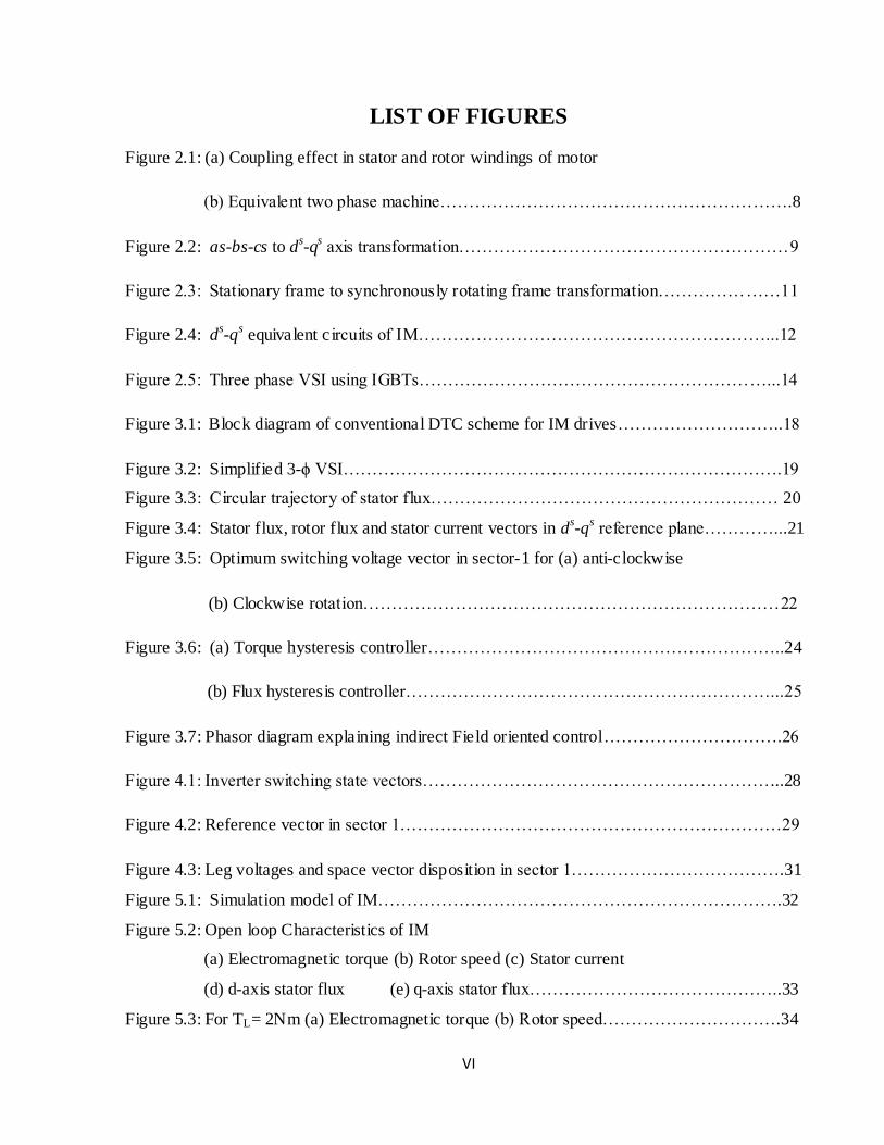
LIST OF FIGURES
Figure 2.1: (a) Coupling effect in stator and rotor windings of motor
(b) Equivalent two phase machine…………………………………………………….8
Figure 2.2: as-bs-cs to ds-q
s axis transformation…………………………………………………9
Figure 2.3: Stationary frame to synchronously rotating frame transformation…………………11
Figure 2.4: ds-q
s equivalent c ircuits of IM……………………………………………………...12
Figure 2.5: Three phase VSI using IGBTs……………………………………………………...14
Figure 3.1: Block diagram of conventional DTC scheme for IM drives………………………..18
Figure 3.2: Simplified 3-ϕ VSI………………………………………………………………….19
Figure 3.3: Circular trajectory of stator flux…………………………………………………… 20
Figure 3.4: Stator flux, rotor flux and stator current vectors in ds-q
s reference plane…………...21
Figure 3.5: Optimum switching voltage vector in sector-1 for (a) anti-clockwise
(b) Clockwise rotation………………………………………………………………22
Figure 3.6: (a) Torque hysteresis controller……………………………………………………..24
(b) Flux hysteresis controller………………………………………………………...25
Figure 3.7: Phasor diagram explaining indirect Field oriented control………………………….26
Figure 4.1: Inverter switching state vectors……………………………………………………...28
Figure 4.2: Reference vector in sector 1…………………………………………………………29
Figure 4.3: Leg voltages and space vector disposition in sector 1……………………………….31
Figure 5.1: Simulation model of IM…………………………………………………………….32
Figure 5.2: Open loop Characteristics of IM
(a) Electromagnetic torque (b) Rotor speed (c) Stator current
(d) d-axis stator flux (e) q-axis stator flux……………………………………..33
Figure 5.3: For TL= 2Nm (a) Electromagnetic torque (b) Rotor speed………………………….34

VII
Figure 5.4: Trajectory of d axis and q axis stator flux in stationary reference frame………… ....35
Figure 5.5: Simulink model of DTC scheme of IM……………………………………………...36
Figure 5.6: Results DTC of IM
(a) Electromagnetic torque (b) Rotor speed (c) d-axis stator flux
(d) q-axis stator flux (e) d-axis stator current (f) q-axis stator current…………....37-38
Figure 5.7: Results of FOC based on SVPWM
(a) Mean value of Phase voltage of inverter (b) Line voltage output of inverter
(c) Electromagnetic torque (d) Rotor speed
(e) q-axis stator flux (f) d-axis stator flux…………………………………………39-40

VIII
LIST OF TABLES
Table 2.1: Switching states of a three phase VSI………………………………………………16
Table 3.1: Applied selected voltage vectors…………………………………………………….22
M.Tech Thesis
NIT Rourkela Page 1
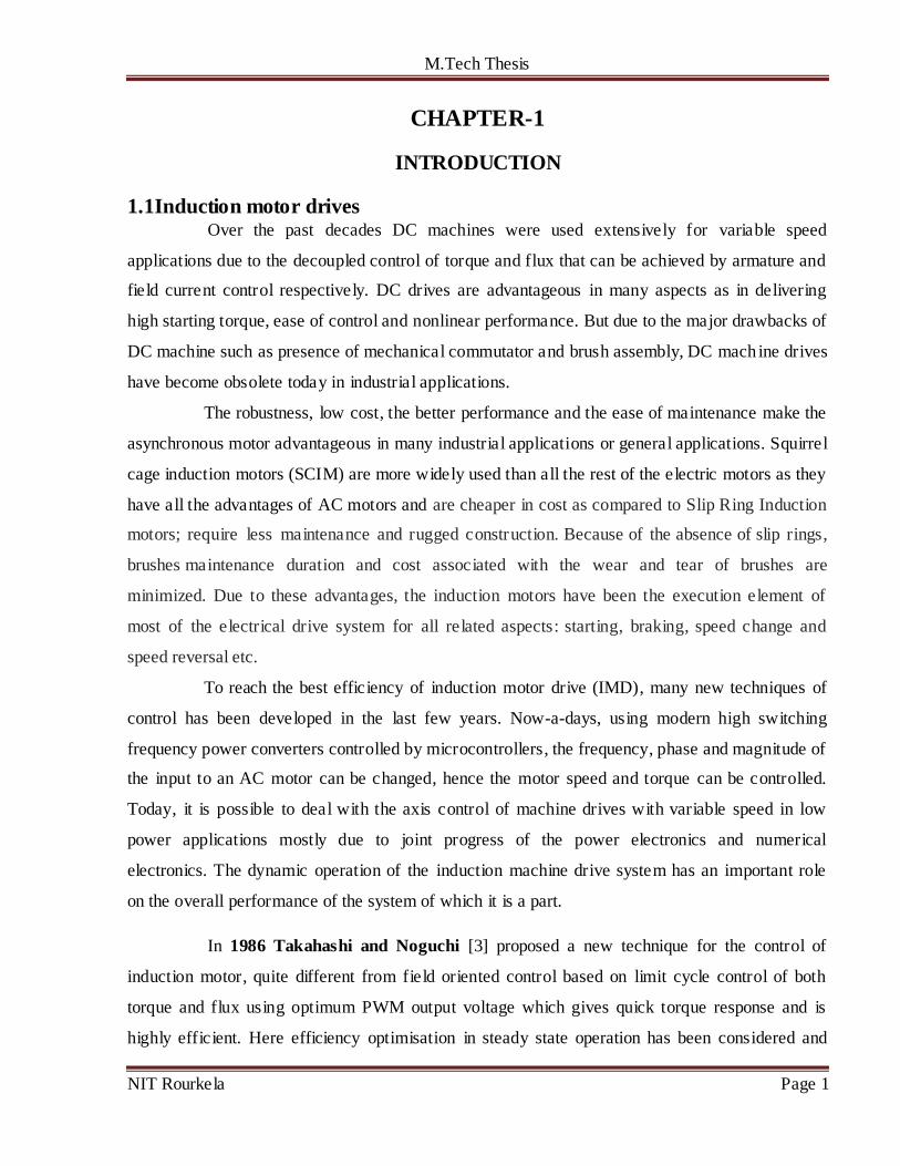
CHAPTER-1
INTRODUCTION
1.1 Induction motor drives Over the past decades DC machines were used extensively for variable speed
applications due to the decoupled control of torque and flux that can be achieved by armature and
field current control respectively. DC drives are advantageous in many aspects as in delivering
high starting torque, ease of control and nonlinear performance. But due to the major drawbacks of
DC machine such as presence of mechanical commutator and brush assembly, DC mach ine drives
have become obsolete today in industrial applications.
The robustness, low cost, the better performance and the ease of maintenance make the
asynchronous motor advantageous in many industrial applications or general applications. Squirrel
cage induction motors (SCIM) are more widely used than all the rest of the electric motors as they
have all the advantages of AC motors and are cheaper in cost as compared to Slip Ring Induction
motors; require less maintenance and rugged construction. Because of the absence of slip rings,
brushes maintenance duration and cost associated with the wear and tear of brushes are
minimized. Due to these advantages, the induction motors have been the execution element of
most of the electrical drive system for all related aspects: starting, braking, speed change and
speed reversal etc.
To reach the best efficiency of induction motor drive (IMD), many new techniques of
control has been developed in the last few years. Now-a-days, using modern high switching
frequency power converters controlled by microcontrollers, the frequency, phase and magnitude of
the input to an AC motor can be changed, hence the motor speed and torque can be controlled.
Today, it is possible to deal with the axis control of machine drives with variable speed in low
power applications mostly due to joint progress of the power electronics and numerical
electronics. The dynamic operation of the induction machine drive system has an important role
on the overall performance of the system of which it is a part.
In 1986 Takahashi and Noguchi [3] proposed a new technique for the control of
induction motor, quite different from field oriented control based on limit cycle control of both
torque and flux using optimum PWM output voltage which gives quick torque response and is
highly efficient. Here efficiency optimisation in steady state operation has been considered and
M.Tech Thesis
NIT Rourkela Page 2
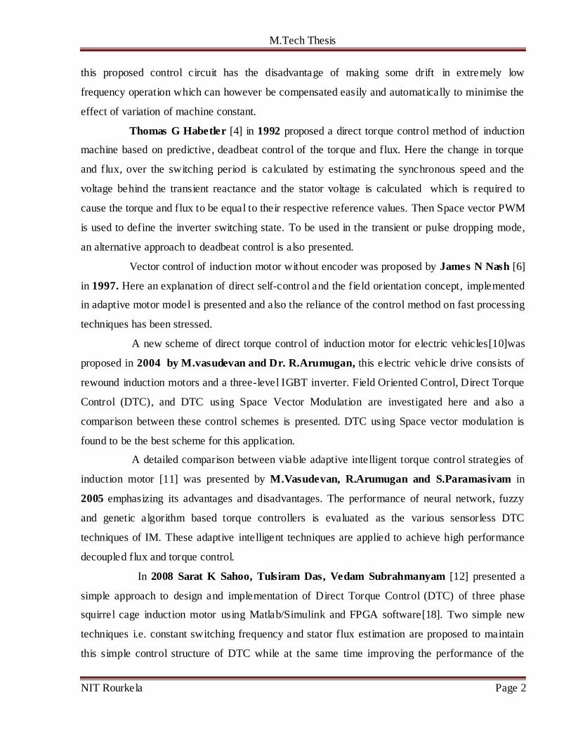
this proposed control circuit has the disadvantage of making some drift in extremely low
frequency operation which can however be compensated easily and automatically to minimise the
effect of variation of machine constant.
Thomas G Habetler [4] in 1992 proposed a direct torque control method of induction
machine based on predictive, deadbeat control of the torque and flux. Here the change in torque
and flux, over the switching period is calculated by estimating the synchronous speed and the
voltage behind the transient reactance and the stator voltage is calculated which is required to
cause the torque and flux to be equal to their respective reference values. Then Space vector PWM
is used to define the inverter switching state. To be used in the transient or pulse dropping mode,
an alternative approach to deadbeat control is also presented.
Vector control of induction motor without encoder was proposed by James N Nash [6]
in 1997. Here an explanation of direct self-control and the field orientation concept, implemented
in adaptive motor model is presented and also the reliance of the control method on fast processing
techniques has been stressed.
A new scheme of direct torque control of induction motor for electric vehicles[10]was
proposed in 2004 by M.vasudevan and Dr. R.Arumugan, this electric vehicle drive consists of
rewound induction motors and a three-level IGBT inverter. Field Oriented Control, Direct Torque
Control (DTC), and DTC using Space Vector Modulation are investigated here and also a
comparison between these control schemes is presented. DTC using Space vector modulation is
found to be the best scheme for this application.
A detailed comparison between viable adaptive intelligent torque control strategies of
induction motor [11] was presented by M.Vasudevan, R.Arumugan and S.Paramasivam in
2005 emphasizing its advantages and disadvantages. The performance of neural network, fuzzy
and genetic algorithm based torque controllers is evaluated as the various sensorless DTC
techniques of IM. These adaptive intelligent techniques are applied to achieve high performance
decoupled flux and torque control.
In 2008 Sarat K Sahoo, Tulsiram Das, Vedam Subrahmanyam [12] presented a
simple approach to design and implementation of Direct Torque Control (DTC) of three phase
squirrel cage induction motor using Matlab/Simulink and FPGA software[18]. Two simple new
techniques i.e. constant switching frequency and stator flux estimation are proposed to maintain
this simple control structure of DTC while at the same time improving the performance of the

M.Tech Thesis
NIT Rourkela Page 3
DTC drives. A simple torque control is introduced to replace the three level hysteresis
comparators to maintain a constant switching frequency. By us ing simple compensator based on
steady state operation, the magnitude and phase error associated with stator flux estimation based
on voltage model is compensated.
A strategy of variable duty ratio control scheme is proposed by Prof.K.B.Mohanty in
2009[15] to increase switching frequency, and adjust the width of hysteresis bands of conventional
DTC according to the switching frequency. This technique minimizes torque and current ripples,
improves torque response, and reduces switching losses in spite of its simplicity.
Direct torque control of induction motor using space vector pulse width modulation
technique was described by S.L.Kaila and H.B.Jani in 2011. The switching instants of different
space vectors are determined for each sampling period in order to minimize the torque ripple in
SVPWM technique.
1.2 Types of control schemes
There are two important steps to design a control system for electrical drives
1. In order to accomplish the analysis and the evaluation of the system, first the drive system has
to be converted into a mathematical model.
2. When external perturbations are present, through an optimal regulator the imposed
response on the system is obtained.
There are two fundamental directions of IM control [1]
Analogue: direct measurement of the machine parameters (mainly the rotor speed), which
are compared to the reference signals through closed control loops.
Digital: estimation of the machine parameters in the sensorless control schemes (without
measuring the rotor speed).
The parameter estimation can be done by implementing following methodologies [1]
•Slip frequency calculation method
•Speed estimation using state equation;
•Estimation based on slot space harmonic voltages;
•Flux estimation and flux vector control;

M.Tech Thesis
NIT Rourkela Page 4
•Direct control of torque and flux;
•Observer-based speed sensorless control;
•Model reference adaptive systems;
•Kalman filtering techniques;
•Sensorless control with parameter adaptation;
•Neural network based sensorless control;
•Fuzzy-logic based sensorless control.
Classification of control techniques for IM from the view point of the controlled signal [1]
[2]:
Scalar control: based on relationships valid in steady state, only magnitude and
frequency of voltage, current and flux linkage space vectors are controlled. Disregards the
coupling effect in the machine.
Vector control: based on relations valid in dynamics state, not only magnitude and
frequency but also instantaneous position of voltage, current and flux linkage space vector are
controlled. The most popular vector control methods are the Field oriented control (FOC) and
DTC.
Scalar controlled drives give somewhat inferior performance, but easy to implement.
Their importance has been diminished recently because of the superior performance of vector
controlled drives which is demanded in many applications [5].
1.2 Direct torque control
DTC was first introduced by Takahashi in 1984 in Japan and by Dopenbrock in 1985 in
Germany [3] [7] and today this control scheme is considered as the world‟s most advanced AC
Drives control technology. This is a simple control technique which does not require coordinate
transformation, PI regulators, and Pulse width modulator and position encoders [20] [25].This
technique results in direct and independent control of motor torque and flux by selecting optimum
inverter switching modes. The electromagnetic torque and stator flux are calculated from the
primary motor inputs e.g. stator voltages and currents [16]. The optimum voltage vector selection
for the inverter is made so as to restrict the torque and flux errors within the hysteresis bands. The

M.Tech Thesis
NIT Rourkela Page 5
advantages of this control technique are quick torque response in transient operation and
improvement in the steady state efficiency.
1.4 MOTIVATION
The electric drives used in industry are Adjustable Speed Drives and in most of these
drives AC motors are applied. Induction motors are the standard in these drives. Induction motors
are today the most widely used ac machines due to the advantageous mix of low cost, reliability
and performance. So effective control of IM parameters e.g. speed, torque and flux is of utmost
importance. From the investigation of the control methods it is known that torque control of IM
can be achieved according to different techniques ranging from inexpensive Volts/Hz ratio
strategy to sophisticated sensorless vector control scheme. But every method has its own
disadvantages like losses, need of separate current control loop, coordinate transformation (thus
increasing the complexity of the controller), torque and current ripple etc.So it is very much
necessary to design a controller to obtain an ideal electric vehicle motor drive system which would
have high efficiency, low torque ripple and minimum current distortion.
1.5 OBJECTIVE
The main objective of this project work is to develop; 1. a control method in order to
achieve superior dynamic response, fast torque response 2.a controller having low inverter
switching frequency, low harmonic losses, high efficiency. The DTC controller has all the above
characteristics to be good a controller. So the objective here is to study the most advanced IM
control method i.e. direct torque control and investigate its performance characteristics.
1.6 OVERVIEW OF THE THESIS
Chapter 2: discusses the mathematical model of three phase induction motor, the concept of
reference frames and the induction motor dynamic equations in various reference frames, the
equations in stationary reference frame are to be applied on further chapters. A brief description of
voltage source inverter is also given in this chapter. A Simulink model of induction motor in
stationary reference frame is given.

M.Tech Thesis
NIT Rourkela Page 6
Chapter 3: introduces the conventional DTC scheme, discusses DTC principle and various
methods of estimating stator flux in detail, a brief idea about the hysteresis controllers is given.
Chapter 4: discusses the basic concept of space vector modulation, pulse pattern generation and
application of space vector pulse width modulation technique to indirect vector control strategy.
Chapter 5: Conventional DTC scheme is simulated by MATLAB/SIMULINK platform. The
model is run for typical conditions of reference speed and applied torque values. Initially the
starting transient of DTC drive for no load condition is observed and later performance of machine
for speed reversal is checked. Flux plot of DTC drive is also shown. Characteristics of motor for
indirect vector control based on SVPWM are shown finally.
Chapter 6: gives summery of the whole work, the conclusion and directions for future work.

M.Tech Thesis
NIT Rourkela Page 7
CHAPTER 2
VOLTAGE SOURCE INVERTER FED INDUCTION MOTOR DRIVES
2.1 Introduction The type of waveforms that the electric drive system deals with is ac waveforms, so
the main objective of power converters needed in adjustable speed drives (ASDs) should produce
an ac output waveform from a dc power supply. The magnitude, frequency, and phase of the
sinusoidal ac outputs should be controllable. According to the type of ac output waveform, the
power converter topologies can be considered as voltage source inverters (VSIs) and current
source inverters (CSIs). The voltage source inverters, where the ac output voltage waveform can
be controlled independently, is the most wide ly used power converters in ASDs and many
industrial applications because they naturally behave as voltage sources as required in these
applications. The output of the VSI is fed to the three phase induction motor which is finally
connected to the load of the drive system.
2.2 Dynamic model of induction motor
The stator of induction motor consists of three phase balanced distributed windings
with each phase separated from other two windings by 120 degrees in space [1]. When current
flows through these windings, three phase rotating magnetic field is produced. The dynamic
behavior of the induction machine is taken into account in an adjustable speed drive system using
a power electronics converter. This machine constitutes an element within a feedback loop. Study
of the dynamic performance of the machine is complex due to coupling effect of the stator and
rotor windings, also the coupling coefficient varies with rotor position. So a set of differential
equations with time varying coefficients describe the machine model [1].
To derive the dynamic model of the machine, the following assumptions are made:
No magnetic saturation;
No saliency effects i.e. machine inductance is independent of rotor position;
Stator windings are so arranged as to produce sinusoidal mmf distributions;
Effects of the stator slots may be neglected;
No fringing of the magnetic circuit;

M.Tech Thesis
NIT Rourkela Page 8
Constant magnetic field intensity, radially directed across the air-gap;
Negligible eddy current and hysteresis effects;
A balanced three phase supply is given to the motor from the power converter. For dynamic
modeling of the motor two axes theory is used [1]. According to this theory the time varying
parameters can be expressed in mutually perpendicular direct (d) and quadrature (q) axis. For the
representation of the d-q dynamic model of the machine a stationary or rotating reference frame is
assumed.
(a) (b)
Fig.2.1 (a) Coupling effect in stator and rotor winding of motor (b) Equivalent two-phase machine
In stationary reference frame the ds and q
s axes are fixed on the stator, whereas these are rotating at
an angle with respect to the rotor in rotating reference frame. The rotating reference frame may
either be fixed on the rotor or it may be rotating at synchronous speed. In synchronously rotating
reference frame with sinusoidal supply the machine variables appear as dc quantities in steady
state condition [24].
2.2.1 Axes transformation
(a) Three phase to two phase transformation
A symmetrical three phase machine is considered with stationary as-bs-cs axes at 120
degree apart as shown in fig.2.2.
a
b
c
ωr
θ
ωr
θ
qs
ds
q
d
M.Tech Thesis
NIT Rourkela Page 9
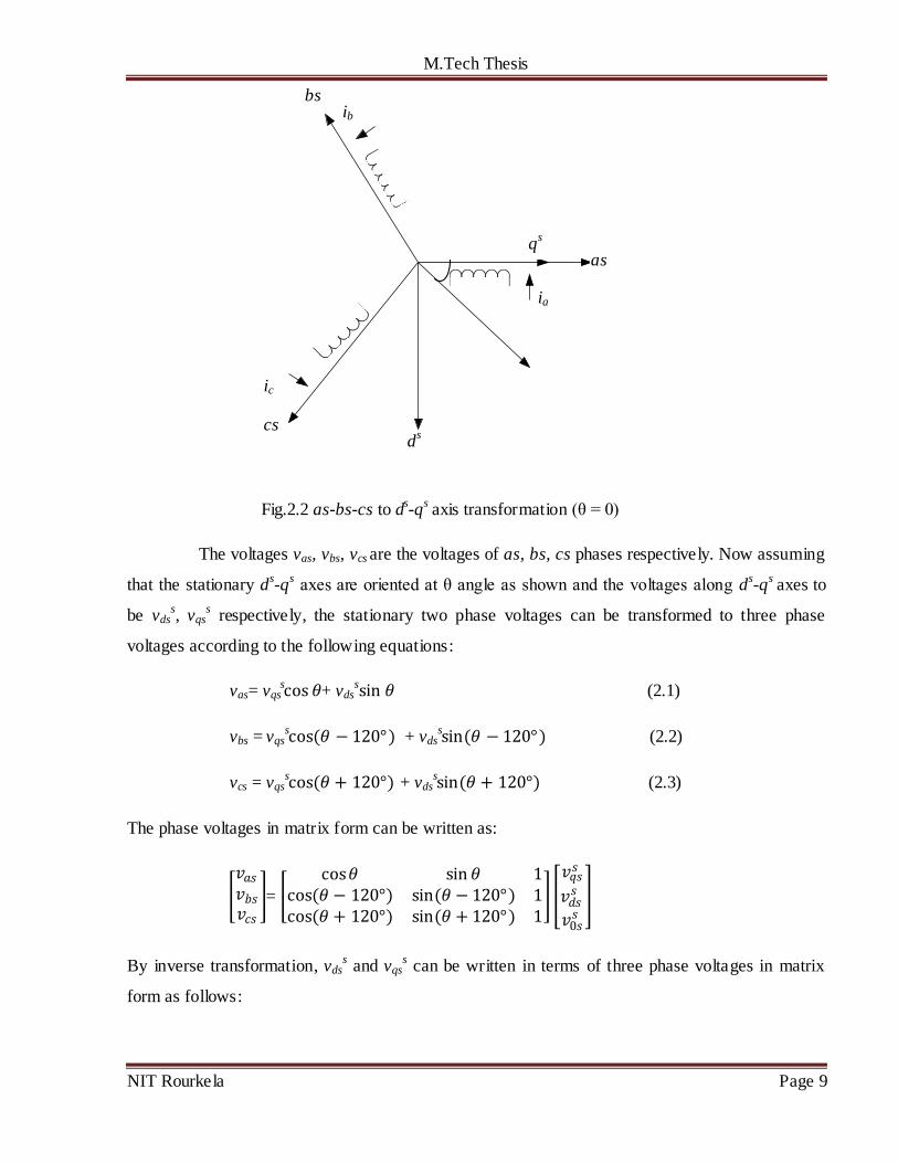
Fig.2.2 as-bs-cs to ds-q
s axis transformation (θ = 0)
The voltages vas, vbs, vcs are the voltages of as, bs, cs phases respectively. Now assuming
that the stationary ds-q
s axes are oriented at θ angle as shown and the voltages along d
s-q
s axes to
be vdss, vqs
s respectively, the stationary two phase voltages can be transformed to three phase
voltages according to the following equations:
vas= vqsscos 𝜃+ vds
ssin 𝜃 (2.1)
vbs = vqsscos(𝜃 − 120°) + vds
ssin(𝜃 − 120°) (2.2)
vcs = vqsscos(𝜃 + 120°) + vds
ssin(𝜃 + 120°) (2.3)
The phase voltages in matrix form can be written as:
𝑣𝑎𝑠𝑣𝑏𝑠
𝑣𝑐𝑠 =
cos𝜃 sin 𝜃 1cos(𝜃 − 120°) sin(𝜃 − 120°) 1cos(𝜃 + 120°) sin(𝜃 + 120°) 1
𝑣𝑞𝑠𝑠
𝑣𝑑𝑠𝑠
𝑣0𝑠𝑠
By inverse transformation, vdss and vqs
s can be written in terms of three phase voltages in matrix
form as follows:
as
bs
cs
qs
ds
ia
ib
ic

M.Tech Thesis
NIT Rourkela Page 10
𝑣𝑞𝑠𝑠
𝑣𝑑𝑠𝑠
𝑣0𝑠𝑠
= 2
3 cos𝜃 cos(𝜃 − 120°) cos(𝜃 + 120°)
sin 𝜃 sin(𝜃 − 120°) sin(𝜃 + 120°)
0.5 0.5 0.5
𝑣𝑎𝑠𝑣𝑏𝑠
𝑣𝑐𝑠
Where v0s = zero sequence component which may or may not present.
For convenient qs axis is aligned with the as-axis i.e. θ = 0 and zero sequence component is
neglected. So the transformation relations are reduced to
vas = vqss (2.4)
vbs= −1
2vqs
s− √3
2vds
s (2.5)
vcs= −1
2vqs
s+
√3
2vds
s (2.6)
vqss = vas (2.7)
vdss= −
1
√3( vbs̶ vcs ) (2.8)
(b) Two phase stationary to two phase synchronously rotating frame transformation
The stationary ds-q
s axes are transformed to synchronously rotating d
e-q
e reference
frame which is rotating at speed ωe with respect to ds-q
s axes with the help of fig.2.3.
The angle between ds and d
e axes is θe = ωet. The voltages vds
s, vqs
s can be converted to
voltages on de-q
e axis according to the following relations:
vds= vqsscos𝜃𝑒 ̶ vds
ssin 𝜃𝑒 (2.9)
vqs = vqsssin 𝜃𝑒 +vds
scos 𝜃𝑒 (2.10)

M.Tech Thesis
NIT Rourkela Page 11
Fig.2.3 Stationary d-q frame to synchronously rotating frame transformation
The transformation of rotating frame parameters to stationary frame is according to the following
relations:
vqss = vqscos 𝜃𝑒 + vdssin 𝜃𝑒 (2.11)
vdss = ̶ vqssin 𝜃𝑒+ vdscos𝜃𝑒 (2.12)
Assuming that the three phase voltages are balanced and sinusoidal given by follow ing
vas = Vmcos(𝜔𝑒 𝑡 + 𝜙) (2.13)
vbs = Vmcos(𝜔𝑒 𝑡 + 𝜙 − 2𝜋/3 ) (2.14)
vcs = Vmcos(𝜔𝑒 𝑡 + 𝜙 + 2𝜋/3 ) (2.15)
Substituting equations (2.13) – (2.15) in equations (2.8) and (2.9) we get
vqss= Vmcos(𝜔𝑒 𝑡 + 𝜙) (2.16)
vdss = ̶ Vmsin(𝜔𝑒𝑡 + 𝜙) (2.17)
qs
ds
q
d θ
θ
ϕ
V̅
vqss
vdss
vds
vqs

M.Tech Thesis
NIT Rourkela Page 12
Substituting (2.16) – (2.17) in (2.9) – (2.10)
vqs = Vmcos 𝜙 (2.18)
vds = ̶ Vmsin (𝜙) (2.19)
From equations (2.18) and (2.19) it is clear that sinusoidal quantities in a stationary frame appear
as dc quantities in a synchronously rotating reference frame.
2.2.2 Motor dynamic model in stationary frame
Machine model in stationary frame by Stanley equations substituting ωe = 0. The stator
circuit equations are written as:
vqss = Rsiqs
s +
𝑑
𝑑𝑡ψqs
s (2.20)
vdss= Rsids
s+
𝑑
𝑑𝑡ψds
s (2.21)
0 = Rriqrs +
𝑑
𝑑𝑡ψqr
s _ ωrψdr
s (2.22)
0 = Rridrs +
𝑑
𝑑𝑡ψdr
s + ωrψqr
s (2.23)
Where ψqss,ψds
s= q-axis and d-axis stator flux linkages
ψqrs,ψdr
s= q-axis and d-axis rotor flux linkages
Rs ,Rr= stator and rotor resistances
ωr = rotor speed and vdr= vqr = 0
(a)
vdss
Rs Lls Llr
Lm
Rr
ωrψqrs
Ψdrs Ψds
s
idss
idrs

M.Tech Thesis
NIT Rourkela Page 13
(b)
Fig.2.4 ds-q
s equivalent circuits
The electromagnetic torque is developed by the interaction of air gap flux and rotor mmf which
can be expressed in general vector form as
Te = 3
2
𝑃
2(ψ̅m) * (I̅r)
The torque equations can be written in stationary frame with corresponding variables as
Te = 3
2
𝑃
2( ψdm
siqr
s ̶ ψqm
sidr
s) (2.24)
= 3
2
𝑃
2( ψdm
siqs
s ̶ ψqm
sids
s) (2.25)
= 3
2
𝑃
2( ψds
siqs
s ̶ ψqs
sids
s) (2.26)
= 3
2
𝑃
2Lm ( idr
siqs
s ̶ iqr
sids
s) (2.27)
= 3
2
𝑃
2( ψdr
siqr
s ̶ ψqr
sidr
s) (2.28)
Rs
Lls Rr
Llr
Lls
Lm vqs
s
ψqss
ψqrs
ωrψdrs
iqss
iqrs

M.Tech Thesis
NIT Rourkela Page 14
2.3 Voltage source inverter
In VSIs the input voltage is maintained constant and the amplitude of the output
voltage is independent of the nature of the load. But the output current waveform as well as
magnitude depends upon nature of load impedance. Three phase VSIs are more common for
providing adjustable frequency power to industrial applications as compared to single phase
inverters. The VSIs take dc supply from a battery or more usually from a 3-ϕ bridge rectifier.
A basic three phase VSI is a six step bridge inverter, consisting of minimum six
power electronics switches (i.e. IGBTs, Thyristors) and six feedback diodes. A step can be defined
as the change in firing from one switch to the next switch in proper sequence. For a six step
inverter each step is of 60º interval for one cycle of 360º. That means the switches would be gated
at regular intervals of 60º in proper sequence to get a three phase ac output voltage at the output
terminal of VSI. Fig.2.5 shows the power circuit diagram of three phase VSI using six IGBTs and
six diodes connected anti parallel to the IGBTs. The capacitor connected in to the input terminals
is to maintain the input dc voltage constant and this also suppresses the harmonics fed back to the
dc source. Three phase load is star connected.
Fig.2.5 Three phase VSI using IGBTs
IM Vdc
S1
S2
S5 S3
S6 S4

M.Tech Thesis
NIT Rourkela Page 15
The six switches are divided into two groups; upper three switches as positive group
(i.e. S1, S3, S5) and lower three as negative group of switches (i.e. S4, S6, S2). There are two
possible gating patterns to the switches i.e. there are two conduction modes: 1. 180º conduction
mode and 2. 120º conduction mode. In each pattern the gating signals are applied and removed at
an interval of 60º of the output voltage waveform. In 180º mode three switches are on at a time,
two from positive group and one from negative group or vice versa, each switch conducts for 180º
of a cycle. In 120º mode each switch conduct for 120º in one cycle and two switches remain
turned on at a time, one from positive group and one from negative group. But no two switches of
the same leg should be turned on simultaneously in both cases as this condition would short circuit
the dc source.
In 120º conduction mode the chances of short circuit of the dc link voltage source is
avoided as each switch conduct for 120º in one cycle, so there is an interval of 60º in each cycle
when no switch is in conduction mode and the output voltage at this time interval is zero. In
general there is a 60º interval between turning off one switch and turning on of the complimentary
switch in the same leg. This 60º interval is sufficient for the outgoing switch to regain its forward
blocking capability.
The standard three-phase VSI topology has eight valid switching states which are
given in Table.1. Of the eight valid switching states, two are zero voltage states(0 and 7 in
Table.1) which produce zero ac line voltages and in this case, the ac line currents freewheel
through either the upper or lower components. The remaining states (1 to 6 in Table .1) are active
states which produce non-zero ac output voltages. The inverter moves from one state to another in
order to generate a given voltage waveform. Thus the resulting ac output line voltages consist of
discrete values of voltages such as 𝑉𝑠
2 , 0,−
𝑉𝑠
2for the topology shown in Fig. 2.5. The
corresponding output voltage waveform is shown in fig.2.6. In 180º mode of conduction the
waveform of ac phase output voltage is stepped one having values 3𝑉𝑠
2,𝑉𝑠
2, 0,−
𝑉𝑠
2 , −
3𝑉𝑠
2and line
voltage waveform is quasi-square wave type having discrete values𝑉𝑠
2 , 0,−
𝑉𝑠
2. In 120º mode the
phase voltage waveform is quasi-square type.

M.Tech Thesis
NIT Rourkela Page 16
Table 2.1 Switching states of a three phase VSI
State Sa Sb Sc Vector
0 0 0 0 V0
1 1 0 0 V1
2 1 1 0 V2
3 0 1 0 V3
4 0 1 1 V4
5 0 0 1 V5
6 1 0 1 V6
7 1 1 1 V7
2.4 Conclusion
In this chapter detail dynamic model of IM is discussed in stationary reference frame.
In order to understand and design vector controlled drives the dynamic model of the machine to be
controlled must be known which could be a good approximation of the real plant. To formulate the
model two axis theory and space phasor notations have been used. It has been proved that space
phasor notation is compact and easier to work with.

M.Tech Thesis
NIT Rourkela Page 17
CHAPTER-3
DIRECT TORQUE CONTROL OF INDUCTION MOTOR
3.1 Introduction
In recent years “induction motor control techniques” have been the field of interest of
many researchers to find out different solutions for induction motor control having the features of
precise and quick torque response, and reduction of the complexity of field oriented control [3]-
[7]. The Direct torque control (DTC) technique has been recognized as the simple and viable
solution to achieve this requirements.DTC is one of the most excellent and efficient control
strategies of induction motor. This technique is based on decoupled control of torque and stator
flux and today it is one of the most actively researched control techniques where the aim is to
control effectively the torque and flux.
3.1.1 Conventional DTC scheme
The conventional DTC scheme is a closed loop control scheme, the important
elements of the control structure being: the power supply circuit, a three phase voltage source
inverter, the induction motor, the speed controller to generate the torque command and the DTC
controller. The DTC controller again consists of torque and flux estimation block, two hysteresis
controllers and sector selection block, the output of the DTC controller is the gating pulses for the
inverter.
The DTC scheme does not require coordinate transformation as all the control
procedures are carried out in stationary frame of reference. So this scheme does not suffer from
parameter variations to the extent that other control techniques do. Also there is no feedback
current control loop due to which the control actions do not suffer from the delays inherent in the
current controllers, no pulse width modulator, no PI controllers, and no rotor speed or position
sensor. So it is a sensorless control technique which operates the motor without requiring a shaft
mounted mechanical sensor. Here on-line torque and flux estimators are used for closing the loop.
Here the torque and stator flux are controlled directly by using hysteresis comparators. Fig.3.1
shows the basic block diagram of conventional DTC scheme [8] [10].
M.Tech Thesis
NIT Rourkela Page 18
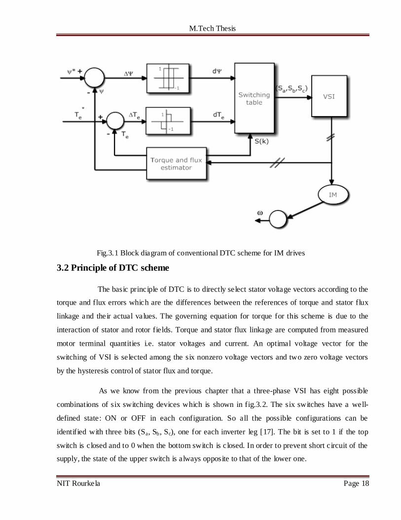
Fig.3.1 Block diagram of conventional DTC scheme for IM drives
3.2 Principle of DTC scheme
The basic principle of DTC is to directly select stator voltage vectors according to the
torque and flux errors which are the differences between the references of torque and stator flux
linkage and their actual values. The governing equation for torque for this scheme is due to the
interaction of stator and rotor fields. Torque and stator flux linkage are computed from measured
motor terminal quantities i.e. stator voltages and current. An optimal voltage vector for the
switching of VSI is selected among the six nonzero voltage vectors and two zero voltage vectors
by the hysteresis control of stator flux and torque.
As we know from the previous chapter that a three-phase VSI has eight possible
combinations of six switching devices which is shown in fig.3.2. The six switches have a well-
defined state: ON or OFF in each configuration. So all the possible configurations can be
identified with three bits (Sa, Sb, Sc), one for each inverter leg [17]. The bit is set to 1 if the top
switch is closed and to 0 when the bottom switch is closed. In order to prevent short circuit of the
supply, the state of the upper switch is always opposite to that of the lower one.
M.Tech Thesis
NIT Rourkela Page 19
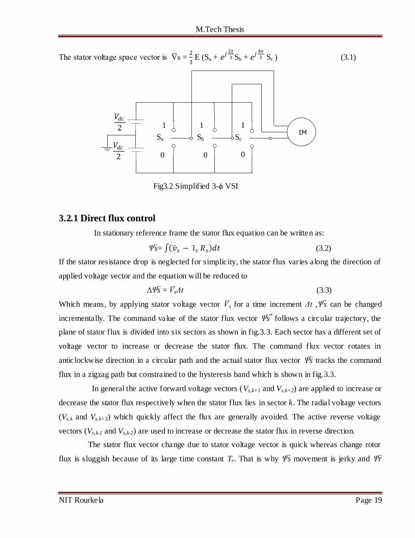
The stator voltage space vector is V̅s = 2
3 E (Sa + 𝑒𝑗
2𝜋
3 Sb + 𝑒𝑗4𝜋
3 Sc ) (3.1)
Fig3.2 Simplified 3-ϕ VSI
3.2.1 Direct flux control
In stationary reference frame the stator flux equation can be written as:
Ψ̅s= �̅�𝑠 − �̅�𝑠 𝑅𝑠 𝑑𝑡 (3.2)
If the stator resistance drop is neglected for simplicity, the stator flux varies along the direction of
applied voltage vector and the equation will be reduced to
ΔΨs̅ = V̅sΔt (3.3)
Which means, by applying stator voltage vector V̅s for a time increment Δt ,Ψ̅s can be changed
incrementally. The command value of the stator flux vector Ψs̅*
follows a circular trajectory, the
plane of stator flux is divided into six sectors as shown in fig.3.3. Each sector has a different set of
voltage vector to increase or decrease the stator flux. The command flux vector rotates in
anticlockwise direction in a circular path and the actual stator flux vector Ψs̅ tracks the command
flux in a zigzag path but constrained to the hysteresis band which is shown in fig.3.3.
In general the active forward voltage vectors (Vs,k+1 and Vs,k+2) are applied to increase or
decrease the stator flux respectively when the stator flux lies in sector k . The radial voltage vectors
(Vs,k and Vs,k+3) which quickly affect the flux are generally avoided. The active reverse voltage
vectors (Vs,k-1 and Vs,k-2) are used to increase or decrease the stator flux in reverse direction.
The stator flux vector change due to stator voltage vector is quick whereas change rotor
flux is sluggish because of its large time constant Tr. That is why Ψ̅s movement is jerky and Ψr̅
𝑉𝑑𝑐2
𝑉𝑑𝑐2
Sa Sb Sc
1
0
1
0
1
0

M.Tech Thesis
NIT Rourkela Page 20
moves uniformly at frequency ωe as it is more filtered. However the average speed of both remains
the same in steady state condition.
Fig.3.3 Circular trajectory of stator flux
3.2.2 Direct torque control
The electromagnetic torque produced due to interaction of stator and rotor flux is
given by the following equation:
Te = 3
2 𝑃
2
𝐿𝑚
𝐿𝑠′ 𝐿𝑟
Ψs̅ * Ψ̅r = 3
2 𝑃
2
𝐿𝑚
𝐿𝑠′ 𝐿𝑟
Ψs Ψr sin 𝛾 (3.4)

M.Tech Thesis
NIT Rourkela Page 21
Fig.3.4 Stator flux, rotor flux and stator current vectors in ds-q
s reference plane
From the above it is clear that torque varies directly as angle between stator flux and
rotor flux i.e. γ. So in order to obtain high dynamic performance it is required to vary γ quickly.
Assuming the rotor is rotating in anticlockwise direction continuously and stator flux lies in sector
k , the active forward voltage vectors (Vs,k+1 and Vs,k+2) are applied to increase γ so as the torque Te.
The radial voltage vectors (Vs,k and Vs,k+3) are used to decrease γ and Te. By applying the reverse
active voltage vectors (Vs,k-1 and Vs,k-2) torque can be decreased rapidly. The two zero voltage
vectors (Vs,0 and Vs,7) are applied to mainta in the flux constant ideally and to decrease the torque
slightly.
3.2.3 Switching selection
A high performance torque control can be established due to the decoupled control of
stator flux and torque in DTC. Fig.3.5 shows an example of stator flux located in sector-1 (S(1))
with the corresponding optimum switching voltage vectors for anti-clockwise and clockwise
rotation of the shaft.
Optimum switching vector selection table given by table 3.1 shows the optimum
selection of the switching vectors in all sectors of the stator flux plane. This table is based on the
value of stator flux error status, torque error status and orientation of stator flux for counter-
clockwise rotation of the shaft [8].
qs
ds
Is
Ψs Ψr
Ψs+ΔΨs
γ Δγ

M.Tech Thesis
NIT Rourkela Page 22
(a) (b)
Fig.3.5 Optimum switching voltage vector in sector-1 for (a) anti-clockwise and (b) clockwise
rotation
Table 3.1 : Applied selected voltage vectors
3.3 Stator flux estimation
For exact calculation of stator flux and torque errors, an accurate estimator of stator flux
is necessary. There are commonly used methods of estimation of flux namely stator voltage
model and current model.
dψ
dTe S(1) S(2) S(3) S(4) S(5) S(6)
1
1 V2 V3 V4 V5 V6 V1
0 V7 V0 V7 V0 V7 V0
-1 V6 V1 V2 V3 V4 V5
0
1 V3 V4 V5 V6 V1 V2
0 V0 V7 V0 V7 V0 V7
-1 V5 V6 V1 V2 V3 V4
I I
ωr
ωr
Vs,3 Vs,3 Vs,2
Vs,2
Vs,6 Vs,6 Vs,5 Vs,5
ds
ds
qs
qs
↑ψs , ↑Te ↓ψs , ↑Te
↑ψs , ↑Te ↓ψs , ↑Te ↑ψs , ↓Te
↓ψs , ↓Te
↓ψs , ↓Te
↑ψs , ↓Te

M.Tech Thesis
NIT Rourkela Page 23
3.3.1 Stator voltage model
This is the simplest method of stator flux estimation, where the machine terminal
voltages and currents are sensed and from the stationary frame equivalent circuit the fluxes are
computed. The estimated stator flux is given by the following equation:
ψdss= (𝑣𝑑𝑠
𝑠 − 𝑖𝑑𝑠𝑠 𝑅𝑠)𝑑𝑡 (3.5)
ψqss= (𝑣𝑞𝑠
𝑠 − 𝑖𝑞𝑠𝑠 𝑅𝑠)𝑑𝑡 (3.6)
ψs = 𝜓𝑑𝑠𝑠2 + 𝜓𝑞𝑠
𝑠2 (3.7)
This method provides accurate flux estimation at high speed but in industrial applications
requiring vector drives at zero start-up this method cannot be used because at low speed stator
resistance drop becomes significant causing inaccurate estimation. Also at low frequency, voltage
signals are very low and dc offset tends to build up at the integration output, as a result ideal
integration becomes difficult.
3.3.2 Current model
In stationary reference frame, current model is globally stable and the drives
operation can be extended down to zero speed. But this model is much complex as compared to
voltage model as here the knowledge of rotor speed and stator current is required to estimate rotor
flux linkage and stator flux can be estimated based on the estimation of rotor flux linkage. From
the dynamic equations of IM in stationary reference frame, stator and rotor flux can be derived
which are given below:
𝑑
𝑑𝑡𝜓 𝑟= ((𝐿𝑚 𝑖𝑠 − �̅�𝑟) 𝑇𝑟 ) ̶ ωrψr (3.8)
Ψ̅s = 𝐿𝑚
𝐿𝑟�̅�𝑟+ σ Lsis (3.9)
Here the equations involve closed loop integration, so there is no integration drift
problem in current model at low speed region. However estimation accuracy is affected due to
motor parameter variation, particularly rotor resistance variation becomes dominant by skin effect
and temperature.
It is ideal to have a hybrid model based on the unique features gained by both models
respectively where the voltage model would be effective at higher speed range and current model
at lower speed range.
M.Tech Thesis
NIT Rourkela Page 24
3.4 Hysteresis controller
DTC of induction motor drives requires two hysteresis controllers. The drive
performance is influenced by the width of the hysteresis bands in terms of flux and torque ripples,
current harmonics and switching frequency of power electronics devices. Current distortion is
reduced by small flux hysteresis band and torque ripple is reduced by small torque hysteresis
bands. In each sampling time, the switching state of the inverter is updated. The inverter state
remains constant, until the output states of the hysteresis controller change within a sampling
interval. If the hysteresis band is fixed, the switching frequency totally depends on the rate of
change of torque and flux.
3.4.1 Torque hysteresis controller
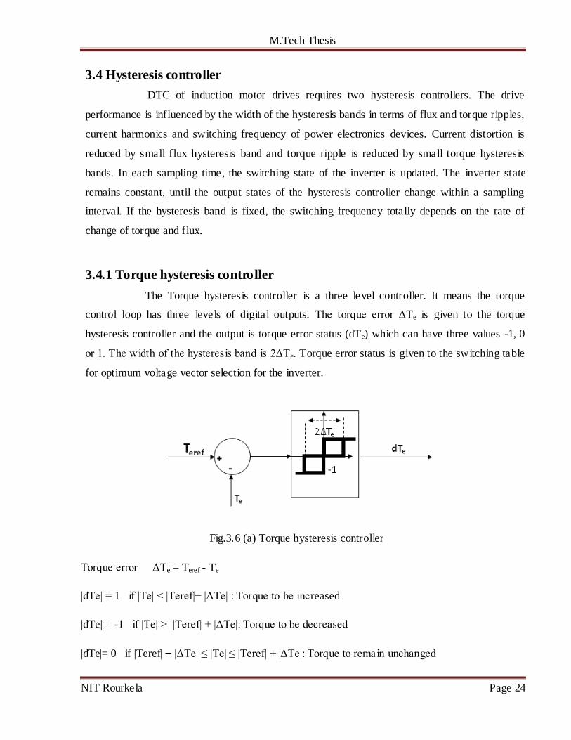
The Torque hysteresis controller is a three level controller. It means the torque
control loop has three levels of digital outputs. The torque error ΔTe is given to the torque
hysteresis controller and the output is torque error status (dTe) which can have three values -1, 0
or 1. The width of the hysteresis band is 2ΔTe. Torque error status is given to the switching table
for optimum voltage vector selection for the inverter.
Fig.3.6 (a) Torque hysteresis controller
Torque error ΔTe = Teref - Te
|dTe| = 1 if |Te| < |Teref|− |ΔTe| : Torque to be increased
|dTe| = -1 if |Te| > |Teref| + |ΔTe|: Torque to be decreased
|dTe|= 0 if |Teref| ̶ |ΔTe| ≤ |Te| ≤ |Teref| + |ΔTe|: Torque to remain unchanged

M.Tech Thesis
NIT Rourkela Page 25
3.4.2 Flux hysteresis controller
The flux hysteresis controller is a two level controller. So the flux control loop has
two digital outputs. The stator flux error Δψs is given to the flux hysteresis controller and the
output is flux error status (dψs) which can have two values 0 and 1. The width of the hysteresis
band is 2Δψs. Flux error status is given to the switching table for optimum voltage vector selection
for the inverter.
Fig.3.6 (b) Flux hysteresis controller
Stator flux error Δψs = ψsref - ψs
The flux is controlled according to the following equations
|dψs| = 1 if |ψs| ≤ |ψsref|− |Δψs|:flux to be increased
|dψs| = 0 if |ψs| ≥ | ψsref|+ |Δψs|: flux to be decreased
3.5 Indirect Field oriented control
In indirect vector control the unit vectors (cos 𝜃𝑒 𝑎𝑛𝑑 sin 𝜃𝑒 ) are generated in feed
forward manner. As shown in the fig. ds-q
s axes is fixed in the stator, d
r-q
r axes rotating at rotor
speed ωr, synchronously rotating axes d-q are rotating ahead of dr-q
r by slip angle θsl, . Rotor field
is directed along d-axis, ωe= ωr + ωsl, so
θe = 𝜔𝑒𝑑𝑡 = (𝜔𝑟 + 𝜔𝑠𝑙) 𝑑𝑡 = θr + θsl (3.10)
The rotor circuit equations in d-q equivalent circuit can be written as:
𝑑
𝑑𝑡 ψdr + Rr idr – (ωe – ωr) ψqr = 0 (3.11)
𝑑
𝑑𝑡 ψqr + Rr iqr + (ωe – ωr) ψdr = 0 (3.12)

M.Tech Thesis
NIT Rourkela Page 26
ψdr = Lr idr+ Lm ids (3.13)
ψqr = Lr iqr+ Lm iqs (3.14)
Fig.3.7 Phasor diagram explaining indirect Field oriented control
For decoupling control ψqr = 0, so ψdr = ψr
Solving all the above eq. we get ψr = 𝐿𝑚 𝑖𝑑𝑠
(1+𝑠 𝑇𝑟) (3.15)
At steady state, the rotor flux is proportional to current ids.
3.5 Conclusion
This chapter included the detail description of the conventional DTC scheme and
principle of indirect FOC scheme. This DTC scheme has many advantages over field oriented
control which has been discussed in this chapter but also has some drawbacks like generation of
flux and torque ripple and variable switching frequency. The flux and torque ripple is due to the
hysteresis controller which can however be reduced significantly by reducing the sampling period.
The variable switching frequency is due to sector change of the stator flux vector.
ds
qs
q
d
d r
iqs
iqss
ψqrs
ψqr = 0
θr
θe
θsl
Ψdrs
idss
ωe
ψqr = ψr
ωr
ids
iqs
I̅s
Rotor axis

M.Tech Thesis
NIT Rourkela Page 27
CHAPTER-4
SPACE VECTOR PULSE WIDTH MODULATION FED INDUCTION
MOTOR DRIVES
4.1 Introduction
The use of PWM drive is advantageous in many ways, for example it obtains its dc
input through uncontrolled rectification of commercial AC mains and has good power factor,
good efficiency, relatively free from regulation problems, it has the ability to operate the motor
with nearly sinusoidal current waveform. The conventional PWM techniques are suitable for
open loop control, for the implementation of a closed loop controlled AC drive Space vector
PWM (SVPWM) technique is applied. In this technique, the switching patterns for the bridge
inverter are generated from the knowledge of stator voltage space phasor. A reference voltage
vector is generated to generate a field synchronous with the rotating voltage vector by utilizing
the different switching states of a three phase bridge inverter [18].
4.2 Theory of Space vector pulse width modulation
When three phase supply is given to the stator of the induction machine, a three
phase rotating magnetic field is produced. Due to this field flux, a three phase rotating voltage
vector is generated which lags the flux by 90º. This field can also be realized by a logical
combination of the inverter switching which is the basic concept of SVPWM.
4.2.1 Realization of voltage space phasor
The three phase bridge inverter has eight possible switching states: six active and two
zero states. The six switches have a well-defined state ON or OFF in each configurations. At a
particular instant, only one switch in each of the three legs is ON. Corresponding to each state of
the inverter, there is one voltage space vector. For example for state zero it is V0, for state 1 it is
V1 and so on. These switching state vectors have equal magnitude but 60º apart from each other
[8]. These vectors can be written in generalized form as follows:

M.Tech Thesis
NIT Rourkela Page 28
Vk = Vdc𝑒𝑗 (
𝑘−1
3)𝜋
k = 1, 2, …...., 6
= 0 k = 0, 7 (4.1)
Where k = inverter state number.
Vdc = dc link voltage of the inverter
The inverter state vectors can be drawn as shown in fig.4.1
Fig.4.1 Inverter switching state vectors
The space bounded by two inverter space vectors is called a sector. So the plane is
divided into six sectors each spanning 60º. In a balanced three phase system the voltage vectors
are 120º apart in space and are represented by rotating vectors, whose projections on the fixed
three phase axes are, sinusoidal waves. So they can be represented as three sinusoidal references
by a voltage reference space vector Vref* or Vs
*. The reference vector is assumed to be rotating in
counter-clockwise direction with respect to ds-axis (α-axis) as shown in fig.4.2 through six
sectors.
The reference space vector can be synthesized by a combination of eight state
vectors and is constant in magnitude at a switching instant ts in case the switching frequency
much higher than the output frequency. In a time average sense the reference vector at that instant
can be approximated by two active voltage states of the inverter. For only certain amount of time
these states are valid.
Vs* = Vktk + Vk+1 tk+1 k = 0, 1, 2……., 7 (4.2)
M.Tech Thesis
NIT Rourkela Page 29
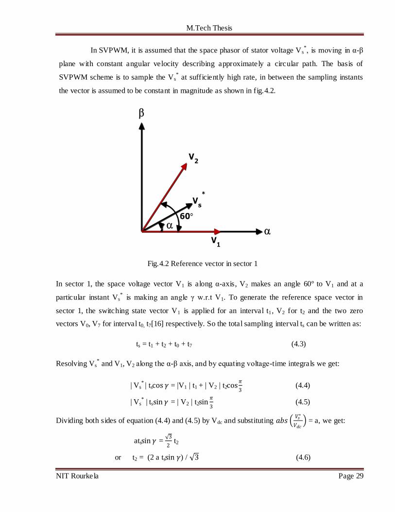
In SVPWM, it is assumed that the space phasor of stator voltage Vs*, is moving in α-β
plane with constant angular velocity describing approximately a circular path. The basis of
SVPWM scheme is to sample the Vs* at sufficiently high rate, in between the sampling instants
the vector is assumed to be constant in magnitude as shown in fig.4.2.
Fig.4.2 Reference vector in sector 1
In sector 1, the space voltage vector V1 is along α-axis, V2 makes an angle 60º to V1 and at a
particular instant Vs* is making an angle γ w.r.t V1. To generate the reference space vector in
sector 1, the switching state vector V1 is applied for an interval t1, V2 for t2 and the two zero
vectors V0, V7 for interval t0, t7[16] respectively. So the total sampling interval ts can be written as:
ts = t1 + t2 + t0 + t7 (4.3)
Resolving Vs* and V1, V2 along the α-β axis, and by equating voltage-time integrals we get:
| Vs* | tscos 𝛾 = |V1 | t1 + | V2 | t2cos
𝜋
3 (4.4)
| Vs* | tssin 𝛾 = | V2 | t2sin
𝜋
3 (4.5)
Dividing both sides of equation (4.4) and (4.5) by Vdc and substituting 𝑎𝑏𝑠 𝑉𝑠∗
𝑉𝑑𝑐 = a, we get:
atssin 𝛾 = √3
2 t2
or t2 = (2 a tssin 𝛾) / √3 (4.6)

M.Tech Thesis
NIT Rourkela Page 30
and a tscos 𝛾= t1 + 1
2t2 (4.7)
Substituting the value of t2 from equation (4.6) in (4.7) and multiplying both sides of resulting
equation by √3
2, we obtain
t1 = 2 a𝑡𝑠
√3sin
𝜋
3− 𝛾 (4.8)
t0 = t7 = ts– (t1 + t2) (4.9)
Where a = modulation index = 𝑎𝑏𝑠 𝑉𝑠
∗
𝑉𝑑𝑐
By the knowledge of t0, t1, t2, t7 , the switching pattern can be determined if the vector is
in sector 1. The four time intervals change simultaneously when Vs* goes from one sector to
another for a particular modulation index a. The full cycle is completed by six similar sectors with
label 1, 2,….,6. As Vs* move over to sector 2, the inverter remains in switching state vector V2 for
time interval t1 and in V3 for time t2. For sector 3: V3 for t1 and V4 for t2 and so on.
4.2.2 Pulse pattern generation
The PWM pattern generation means the generation of gating pulses for the six switches of the
inverter, for correct interva l so that appropriate switching state vectors are active for the
appropriate time intervals as the reference space vector moves over a full cycle.
In order to obtain minimum switching frequency, it is desired that only one phase of
the inverter changes state from +𝑉𝑑𝑐
2 to −
𝑉𝑑𝑐
2 while changing the switching vectors. So the
arrangement of the switching sequence should be such that the transition from one state to the next
state is performed by switching only one inverter phase. This is done by switch ing the inverter
legs in a sequence starting from one zero state and ending at another zero state. Fig.4.3 shows the
optimum inverter phase to dc center tap voltages. It can be noted that the switching frequency of
the inverter is half of the sampling frequency [8] [14].

M.Tech Thesis
NIT Rourkela Page 31
Fig.4.3 Leg voltages and space vector disposition in sector 1
The mean values of the phase to center tap voltages (VA0, VB0, VC0) can be evaluated, averaging
over one sampling period ts as follows:
V̅A0 = Vdc
2ts (−
t0
2+ t1 + t2 +
t0
2) (4.10)
V̅B0 = Vdc
2ts (−
t0
2− t1 + t2 +
t0
2) (4.11)
V̅C0 = Vdc
2ts (−
t0
2− t1 − t2 +
t0
2) (4.12)
Substituting the values of t1, t2 in above three equations
V̅A0 = a Vdc
√3sin(𝛾 +
𝜋
3) (4.13)
V̅B0 = a Vdcsin(𝛾 −𝜋
6) (4.14)
V̅C0 = - V̅A0 (4.15)
4.4 Conclusion
The mean value of the phase voltages obtained by SVPWM technique has triple
harmonics which is eliminated in line voltage. The peak value of the line voltage is 15% more than
that in sine PWM at maximum modulation index, so this method of PWM generation gives better
utilization of dc bus voltage for inverter.

M.Tech Thesis
NIT Rourkela Page 32
CHAPTER-5
SIMULATION MODELS, RESULTS AND DISCUSSIONS
5.1 Simulation model of IM
The three phase induction motor model is simulated by using the Matlab/Simulink.
Using the set of equations provided in chapter 2, the Model is implemented. Figure 5.1 depicts the
complete Simulink model of IM. The performance of the motor is first checked out for no load
condition and then the load torque of 2Nm is applied and performance characteristics are drawn.
The specification of the IM used is 1.5KW, 1440 rpm, 4 pole, 3-phase with parameters: Rs = 7.83
ohm, Rr= 7.55 ohm, Ls= Lr = 0.4751 H, Lm= 0.4535 H, J= 0.06 Kg.m2, B= 0.01 Nm.sec/rad.
Fig.5.1 Simulation model of IM
Continuous
powergui
Phis
Phis_q
Nr
is_a
t
Phis_d
Te
wr
-2
T
v as
v bs
v cs
taul
isa
omegar
Nr
Te
ids
iqs
phids
phiqs
phis
wre
INDUCTION
MOTOR
Clock
C
B
A

M.Tech Thesis
NIT Rourkela Page 33
Results for no load condition, (TL = 0)
Fig.5.2 (a) Electromagnetic torque
Fig.5.2(b) Rotor speed
Fig.5.2(c) Stator current
0 0.5 1 1.5 2 2.5 3 3.5 4 4.5 5-6
-4
-2
0
2
4
6
8
10
Time(sec)
To
rqu
e(N
m)
0 0.5 1 1.5 2 2.5 3 3.5 4 4.5 5-20
0
20
40
60
80
100
120
140
160
Time(sec)
Ro
tor
sp
eed
(rad
/sec)
0 0.5 1 1.5 2 2.5 3 3.5 4 4.5 5-10
-8
-6
-4
-2
0
2
4
6
8
10
Time(sec)
Sta
tor
cu
rren
t(A
mp
)
0.05 0.1 0.15 0.2-10
-5
0
5

M.Tech Thesis
NIT Rourkela Page 34
Fig.5.2 (d) d-axis stator flux
Fig.5.2 (e) q-axis stator flux
For TL = 2 Nm
Fig.5.3 (a) Electromagnetic torque
0 0.5 1 1.5 2 2.5 3 3.5 4 4.5 5-3
-2
-1
0
1
2
3
Time(sec)
d-a
xis
sta
tor
flu
x(W
b)
0.05 0.1 0.15 0.2
-1
0
1
0 0.5 1 1.5 2 2.5 3 3.5 4 4.5 5-3
-2
-1
0
1
2
3
Time(sec)
q-a
xis
sta
tor
flu
x(W
b)
0.05 0.1 0.15 0.2
-1
0
1
0 0.5 1 1.5 2 2.5 3 3.5 4 4.5 5-6
-4
-2
0
2
4
6
8
10
Time(sec)
To
rqu
e(s
ec)

M.Tech Thesis
NIT Rourkela Page 35
Fig.5.3 (b) Rotor speed
Fig.5.4 Trajectory of d axis and q axis stator flux in stationary reference frame
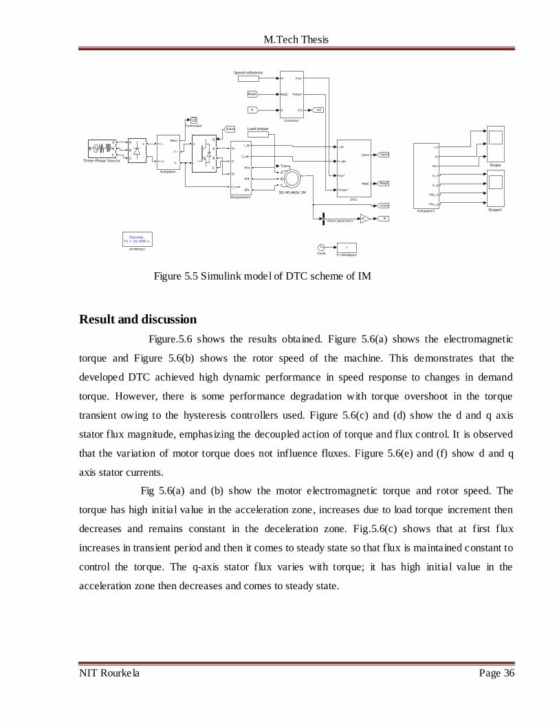
6.2 Simulation of DTC scheme
A direct torque control algorithm of Induction motor drive has been simulated using
Matlab/Simulink. The reference flux linkage is taken as 1 V.s and load torque applied is 200N-
m.The motor is fed from an IGBT PWM inverter (Universal bridge). The MATLAB/ SIMULINK
model for switching logic is developed. The transient performance of the developed DTC model
has been tested by applying a load torque command on the mechanical dynamics. The model is
run for typical conditions of reference speed and applied torque value. Figure 5.2 depicts the
complete Simulink model of DTC scheme of IM.A 50HP, 460V, 60Hz, 4pole, 3-phase induction
motor is used for the simulation. The parameters of the IM are given in appendix A.
0 0.5 1 1.5 2 2.5 3 3.5 4 4.5 50
20
40
60
80
100
120
140
160
Time(sec)
Ro
tor
sp
eed
(rad
/sec)
-0.6 -0.4 -0.2 0 0.2 0.4 0.6 0.8 1 1.2-0.8
-0.6
-0.4
-0.2
0
0.2
0.4
0.6
0.8
phids(Wb)
ph
iqs(W
b)
M.Tech Thesis
NIT Rourkela Page 36
Figure 5.5 Simulink model of DTC scheme of IM
Result and discussion
Figure.5.6 shows the results obtained. Figure 5.6(a) shows the electromagnetic
torque and Figure 5.6(b) shows the rotor speed of the machine. This demonstrates that the
developed DTC achieved high dynamic performance in speed response to changes in demand
torque. However, there is some performance degradation with torque overshoot in the torque
transient owing to the hysteresis controllers used. Figure 5.6(c) and (d) show the d and q axis
stator flux magnitude, emphasizing the decoupled action of torque and flux control. It is observed
that the variation of motor torque does not influence fluxes. Figure 5.6(e) and (f) show d and q
axis stator currents.
Fig 5.6(a) and (b) show the motor electromagnetic torque and rotor speed. The
torque has high initial value in the acceleration zone, increases due to load torque increment then
decreases and remains constant in the deceleration zone. Fig.5.6(c) shows that at first flux
increases in transient period and then it comes to steady state so that flux is maintained constant to
control the torque. The q-axis stator flux varies with torque; it has high initial value in the
acceleration zone then decreases and comes to steady state.
Discrete,Ts = 2e-006 s.
powergui
A
B
C
+
-
g
A
B
C
+
-
t
To Workspace
A
B
C
Three-Phase Source
Terminator
i_a
wr
Tem
is_d
is_q
Phis_d
Phis_q
Subsystem1
Meas.V L-
V L+
V +
V -
Subsystem
Speed reference
Scope1
Scope
-K-
I_ab
V_abc
Ta
Tc
Tb
V_com
MTa
MTb
MTc
Measurement
Load torque
ctrl
motor
N
MagC
Gates
N
MagC
Gates
I_ab
V_abc
Flux*
Torque*
Gates
MagC
DTC
N*
MagC
N
Flux*
Torque*
Ctrl
Controller
Clock
mA
B
C
Tm
50 HP,460V IM
<Rotor speed (wm)>

M.Tech Thesis
NIT Rourkela Page 37
Fig.5.6 (a) Electromagnetic torque
Fig.5.6 (b) Rotor speed
Fig.5.6 (c) d-axis stator flux
0 0.5 1 1.5 2 2.5 3-500
-300
-200
0
200
300
500
Time(sec)
To
rqu
e(N
.m)
0 0.5 1 1.5 2 2.5 3-25
0
25
50
100
150
200
Time(sec)
Ro
tor
sp
eed
(rad
/sec)
0 0.5 1 1.5 2 2.5 3-1
-0.8
-0.6
-0.4
-0.2
0
0.2
0.4
0.6
0.8
1
Time(sec)
d-a
xis
sta
tor
flu
x(W
b)

M.Tech Thesis
NIT Rourkela Page 38
Fig.5.6 (d) q-axis stator flux
Fig.5.6(e) d-axis stator current
Fig.5.6 (f) q-axis stator current
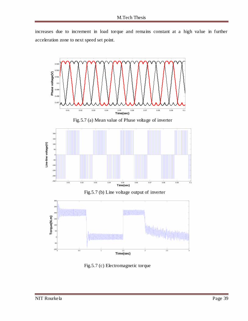
Results of SVPWM based FOC scheme
Fig 5.7(a) and (b) show the mean value of inverter output voltages by SVPWM.
Fig.5.7(c) and (d) show the motor torque and rotor speed in case of FOC based on SVPWM. The
torque has high initial value in acceleration zone then decreases in constant speed region, again
0 0.5 1 1.5 2 2.5 3-1
-0.8
-0.6
-0.4
-0.2
0
0.2
0.4
0.6
0.8
1
Time(sec)
q-a
xis
sta
tor
flu
x(W
b)
0 0.5 1 1.5 2 2.5 3
-50
0
50
100
200
Time(sec)
q-a
xis
sta
tor
cu
rren
t(A
mp
)
0 0.5 1 1.5 2 2.5 3-200
-100
-50
0
50
100
Time(sec)
d-a
xis
sta
tor
cu
rren
t(A
mp
)
M.Tech Thesis
NIT Rourkela Page 39
increases due to increment in load torque and remains constant at a high value in further
acceleration zone to next speed set point.
Fig.5.7 (a) Mean value of Phase voltage of inverter
Fig.5.7 (b) Line voltage output of inverter
Fig.5.7 (c) Electromagnetic torque
0.01 0.02 0.03 0.04 0.05 0.06 0.07 0.08 0.09 0.1
0.497
0.498
0.499
0.5
0.501
0.502
0.503
Time(sec)
Ph
ase v
olt
ag
e(V
)
0.01 0.02 0.03 0.04 0.05 0.06 0.07 0.08 0.09 0.1-250
-200
-150
-100
-50
0
50
100
150
200
Time(sec)
Lin
e-l
ine v
olt
ag
e(V
)
0 0.5 1 1.5 2 2.5 3-100
-50
0
50
100
150
200
250
300
Time(sec)
To
rqu
e(N
.m)

M.Tech Thesis
NIT Rourkela Page 40
Fig.5.7 (d) Rotor speed
Fig.5.7 (e) q-axis stator flux
Fig.5.7 (f) d-axis stator flux
0 0.5 1 1.5 2 2.5 30
20
40
60
80
100
120
140
160
Time(sec)
Ro
tor
sp
eed
(rad
/sec)
0 0.5 1 1.5 2 2.5 3-2
-1.5
-1
-0.5
0
0.5
1
1.5
2
Time(sec)
q-a
xis
sta
tor
flu
x(W
b)
0 0.5 1 1.5 2 2.5 3-2
-1.5
-1
-0.5
0
0.5
1
1.5
2
Time(sec)
d-a
xis
sta
tor
flu
x(N
.m)
M.Tech Thesis
NIT Rourkela Page 41
CHAPTER-6
CONCLUSIONS AND FUTURE WORKS
6.1 Summery and conclusions
For any IM drives, Direct torque control is one of the best controllers proposed so far.
It allows decoupled control of motor stator flux and electromagnetic torque. From the analysis it is
proved that, this strategy of IM control is simpler to implement than other vector control methods
as it does not require pulse width modulator and co-ordinate transformations. But it introduces
undesired torque and current ripple.
DTC scheme uses stationary d-q reference frame with d-axis aligned with the stator
axis. Stator voltage space vector defined in this reference frame control the torque and flux. The
main inferences from this work are:
1. In transient state, by selecting the fastest accelerating voltage vector which produces
maximum slip frequency, highest torque response can be obtained.
2. In steady state, the torque can be maintained constant with small switching frequency by
the torque hysteresis comparator by selecting the accelerating vector and the zero voltage
vector alternately.
3. In order to get the optimum efficiency in steady state and the highest torque response in
transient state at the same time, the flux level can be automatically adjusted.
4. If the switching frequency is extremely low, the control circuit makes some drift which
can be compensated easily to minimize the machine parameter variation.
The estimation accuracy of stator flux is very much essential which mostly depends on stator
resistance because an error in stator flux estimation will affect the behavior of both torque and flux
control loops. The torque and current ripple can be minimized by employing space vector
modulation technique.

M.Tech Thesis
NIT Rourkela Page 42
6.2 Future Scope of work
In conventional DTC scheme, high torque ripple is produced because the selected
voltage space vector is applied for the entire switching period irrespective of the magnitude of the
torque error. This torque ripple can be minimized in order to achieve a better drive performance,
by varying the duty ratio of the selected voltage vector during each switching period, based on the
magnitude of the torque error and position of the stator flux. This constitutes the basic of SVPWM
technique. So the future work is to simulate DTC scheme based on SVPWM technique and to
have comparative study of conventional DTC scheme and DTC-SVM scheme.

M.Tech Thesis
NIT Rourkela Page 43
REFERENCES
[1] B. K.Bose. 1997. Power Electronics and Variable Frequency Drives. IEEE Press, New York.
[2] Kazmierkowski, R.Krishnan, Blaabjerg, Control in Power Electronics, Selected Problems.
[3] Takahashi Isao, Noguchi Toshihiko, „‟A New Quick-Response and High-Efficiency Control
Strategy of an Induction Motor‟‟, IEEE Transactions on Industry Applications, Vol. IA-22
No-5, Sept/Oct 1986.
[4] Thomas G.Habetler, Francesco Profumo, Michele Pastorelli and Leon M. Tolbert “Direct
Torque Control of IM using Space Vector Modulation” IEEE Transactions on Industry
Applications, Vol.28, No.5, Sept/Oct 1992.
[5] E.Bassi, P. Benzi, S. Buja, “A Field Orientation Scheme for Current-Fed Induction Motor
Drives Based on the Torque Angle Closed-Loop Control” IEEE Transactions on Industry
Applications, Vol. 28, No. 5, Sept./ Oct. 1992.
[6] James N. Nash, “Direct Torque Control, Induction Motor Vector Control Without an
encoder” IEEE Trasaction on Industry applications,Vol.33,No.2,March/April 1997.
[7] M. Depenbrock, „‟Direct Self-Control (DSC) of Inverter-Fed Induction Machine‟‟, IEEE
Transactions on Power Electronics, Vol.3, No.4, Oct.1988.
[8] Cristian Lascu, Boldea, Blaabjerg “A Modified Direct Torque Control for Induction Motor
Sensorless Drive” IEEE transaction on Industry Applications, Vol.36, No.1, Jan/Feb 2000.
[9] Anthony Purcell, P. Acarnley, “Enhanced Inverter Switching for Fast Response Direct Torque
Control” IEEE Transactions on Power Electronics, Vol. 16, No. 3, may 2001. [10] M.Vasudevan, R.Arumugam “New Direct Torque Control Scheme of Induction Motor for
Electric vehicle” Proceeding of control conference,5th
Asian,Vol.2, 2004.
[11] M.Vasudevan, R.Arumugam, S.Paramasivam“ High performance adaptive Intelligent DTC
Schemes for induction motor drives” SJEE, Vol.2, No1,May 2005.
[12]Sarat K. Sahoo, G. Tulsi Ram Das, Vedam Subrahmanyam “Implementation and Simulation
of DTC scheme with the use of FPGA scheme” ARPN Journal of Engineering and Applied
Sciences, Vol.3. No.2, April 2008.
[13] Ehsan Hassankhan, Davood A. Khaburi,”DTC-SVM Scheme for Induction Motors Fed
with a Three-level Inverter”, World Academy of Science, Engineering and Technology 2008.

M.Tech Thesis
NIT Rourkela Page 44
[14] L. Bouras, M. Kadjoudj, “Vector control of induction motor based Space Vector Modulation”
Electronics and Telecommunications, Vol.50, No.1, 2009.
[15] Prof.K.B.Mohanty “A Direct Torque Controlled Induction Motor with Variable Hysteresis
Band” 11th International Conference on Computer Modelling and Simulation, UK Sim 2009.
[16] Zhifeng Zhang, Renyuan Tang, “Novel Direct Torque Control Based on Space Vector With
Modulation Adaptive Stator Flux Observer for Induction Motors” IEEE Transactions on
Magnetics, Vol. 46, No. 8, August 2010.
[17] T.Nasser et al, “direct torque control of induction motor based on artificial neural networks
With estimate and regulation speed using the MRAS and neural pi controller” Journal of
Theoretical and Applied Information Technology” 2010.
[18] S Allirani, V Jagannathan, “High Performance Direct Torque Control of Induction
Motor Drives Using Space Vector Modulation” IJCSI, Vol. 7, Issue 6, November 2010.
[19] K. Kaur, S. Duvvuri, S. Singh, “Simulation of Indirect Vector Controlled Induction Motor
Drive” IEEE International Conference on Advanced Computing & Comm.Techno.2011.
[20] Giovanna Oriti and Alexander L. Julian,“Three-Phase VSI with FPGA-Based Multisampled
Space Vector Modulation” IEEE transactions on industry applications, Vol. 47, No. 4,
July/August 2011.
[21] AuzaniJidin, NikIdris, Mohamed Yatim, “Simple Dynamic Overmodulation Strategy For
Fast Torque Control in DTC of Induction Machines With Constant-Switching-Frequency
Controller”IEEE transactions on industry applications, Vol. 47, No. 5, Sept/Oct 2011.
[22]A. Mishra, P.Choudhary, “Speed Control Of An Induction Motor By Using Indirect Vector
Control Method” IJETAE,Volume 2, Issue 12, December 2012.
[23] H. Arabaci and O. Bilgin, “Squirrel Cage of Induction Motors Simulation via Simulink”
International Journal of Modeling and Optimization, Vol. 2, No. 3, June 2012.
[24] Sifat Shah, A. Rashid, MKL Bhatti, “Direct Quadrate (D-Q) Modeling of 3-Phase Induction
Motor Using MatLab / Simulink” Canadian Journal on Electrical and Electronics Engineering
Vol. 3, No. 5, May 2012.
[25] Nasir Uddin, Muhammad Hafeez, “FLC-Based DTC Scheme to Improve the Dynamic
Performance of an IM Drive” IEEE transactions on industry applications, Vol. 48, No. 2
March/April 2012.
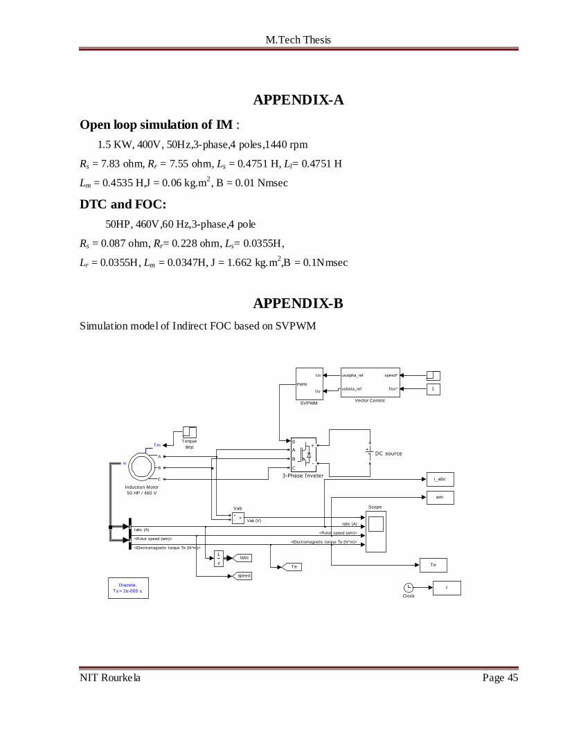
M.Tech Thesis
NIT Rourkela Page 45
APPENDIX-A
Open loop simulation of IM :
1.5 KW, 400V, 50Hz,3-phase,4 poles,1440 rpm
Rs = 7.83 ohm, Rr = 7.55 ohm, Ls = 0.4751 H, Ll= 0.4751 H
Lm = 0.4535 H,J = 0.06 kg.m2, B = 0.01 Nmsec
DTC and FOC:
50HP, 460V,60 Hz,3-phase,4 pole
Rs = 0.087 ohm, Rr= 0.228 ohm, Ls= 0.0355H,
Lr = 0.0355H, Lm = 0.0347H, J = 1.662 kg.m2,B = 0.1Nmsec
APPENDIX-B
Simulation model of Indirect FOC based on SVPWM
Discrete,
Ts = 2e-005 s.
speed*
f lux*
usalpha_ref
usbeta_ref
Vector Control
v+-
Vab
z
1
Torque
step
Te
wm
i_abc
t
Scope
Ux
Uy
PWM
SVPWM
m
A
B
C
Tm
Induction Motor
50 HP / 460 V
Te
Iabc
speed
DC source
1
Clock
g
A
B
C
+
-
3-Phase Inveter
<Rotor speed (wm)>
<Rotor speed (wm)>
Iabc (A)
Iabc (A)
<Electromagnetic torque Te (N*m)>
<Electromagnetic torque Te (N*m)>
Vab (V)

M.Tech Thesis
NIT Rourkela Page 46
b. DTC controller
Matlab coding:
a. For sector selection
functionSn = S(Ux,Uy)
theta=atan2(Uy,Ux)*180/pi;
if theta>=0&&theta<60
Sn=1;
elseif theta>=60&&theta<120
Sn=2;
elseif theta>=120&&theta<180
Sn=3;
elseif theta>=-180&&theta<-120
Sn=4;
elseif theta>=-120&&theta<-60
Sn=5;
elseSn=6;
end
b. For duty cycle calculation
function [duty1,duty2,duty0] = fcn(alpha,z0,z1,z2,m)
z3=sqrt(z0*z0+z1*z1);
%vref=2*z2/3
duty1=(2/sqrt(3))*sin(pi/3-alpha)*(m);
duty2=(2/sqrt(3))*sin(alpha)*(m);
duty0=1-(duty1+duty2);
2
MagC
1
Gates
1/z
1/z
V_abc
I_ab
Torque
Flux
angle
Torque and flux calculator
H _Te
H _Phi
Flux est
Sector
Gates
MagC
Switching table
Pulses RF Pulses
Switching control
NoOp
NoOp
Flux_angle sector
Flux sector seeker
Torque
Flux*
Torque*
Flux
H_Te
H_Phi
Flux_est
hysteresis controller
4
Torque*
3
Flux*
2
V_abc
1
I_ab

M.Tech Thesis
NIT Rourkela Page 47