Study of heat transfer for a pair of rectangular jets impinging on an inclined surface
15
Study of heat transfer for a pair of rectangular jets impinging on an inclined surface Subrata Roy * , Paresh Patel 1 Department of Mechanical Engineering, Kettering University, 1700 West Third Avenue, Flint, MI 48504-4898, USA Received 5 July 2001; received in revised form 24 July 2002 Abstract Critical design parameters in jet impingement heat transfer like nozzle hydraulic diameter, jet angle and velocity, physical properties of the fluid, and nozzle-to-target plane spacing are the subject. This paper identifies the dominant fluid-thermal characteristics of a pair of rectangular air jets impinging on an inclined surface. Heat transfer modes and flow characteristics are studied with eight different Reynolds numbers ranging from 500 to 20 000. Local and average Nusselt numbers are evaluated with two different boundary conditions on three specified lines located on the inclined surface. The correlation between stagnation Nusselt number and Reynolds number is presented. Turbulent intensity and wall y þ distributions are compared on three lines parallel to the incline. The effect of jet impingement angle on local and average Nusselt number is also documented. Finally, a correlation between the average Nusselt number, nozzle exit Reynolds number and the jet angle is documented. Ó 2002 Elsevier Science Ltd. All rights reserved. Keywords: Climate control; CFD; Inclined surface; Impinging jets; Rectangular slots 1. Introduction Jet impingement heat transfer has been employed in many practical applications for cooling and drying be- cause of its easy implementation and high heat transfer rate. Examples include turbine blade film cooling, bearing cooling, electronics cooling, vehicle windshield deicing/defogging, drying of paper, and glass tempering. In many of these applications, the Nusselt number (Nu) distribution resulting from the jet attachment to the target plane, the trajectory and physical properties of the jet are critical design parameters. The specific interest is air issuing from two rectangular openings and impinging upon an inclined surface that is common in vehicle windshield climate control application. Impingement of single and multiple jets on surface has been extensively investigated in the literature [1– 16,21,22]. Impingement of single circular jet on per- pendicular and inclined plate in Lamont and Hunt [1] showed surface pressure distribution on entire im- pingement region for varying pressure ratios and plate angles ranging from 30° to 90°. Bernard et al. in [2] used various experimental techniques to describe the flow of several jets impinging on a plane wall. Polat et al. [3] presented a review of numerical studies related to axi- symmetric impinging jets. More reviews were docu- mented by Martin [4], and Downs and James [5]. Lee et al. [6] showed local heat transfer from an elliptical jet impingement on a flat plate. An array of elliptical jets has been studied extensively by Arjocu and Liburdy [7] to understand the dominant local heat transfer modes for low Reynolds number (Re) such as 300 and 1500, while Martin [8] has identified optimum impingement and separation distances for heat transfer for a wider flow range, 2500 6 Re 6 4 000 000. The effects of Re, nozzle geometry and the separation distance were also studied by Colucci and Viskanta [9]. International Journal of Heat and Mass Transfer 46 (2003) 411–425 www.elsevier.com/locate/ijhmt * Corresponding author. Tel.: +1-810-762-9949; fax: +1-810- 762-7860. E-mail addresses: [email protected] (S. Roy), patel@ erc.msstate.edu (P. Patel). 1 Currently at Mississippi State University. 0017-9310/03/$ - see front matter Ó 2002 Elsevier Science Ltd. All rights reserved. PII:S0017-9310(02)00295-8
-
Upload
subrata-roy -
Category
Documents
-
view
216 -
download
1
Transcript of Study of heat transfer for a pair of rectangular jets impinging on an inclined surface

Study of heat transfer for a pair of rectangular jetsimpinging on an inclined surface
Subrata Roy *, Paresh Patel 1
Department of Mechanical Engineering, Kettering University, 1700 West Third Avenue, Flint, MI 48504-4898, USA
Received 5 July 2001; received in revised form 24 July 2002
Abstract
Critical design parameters in jet impingement heat transfer like nozzle hydraulic diameter, jet angle and velocity,
physical properties of the fluid, and nozzle-to-target plane spacing are the subject. This paper identifies the dominant
fluid-thermal characteristics of a pair of rectangular air jets impinging on an inclined surface. Heat transfer modes and
flow characteristics are studied with eight different Reynolds numbers ranging from 500 to 20 000. Local and average
Nusselt numbers are evaluated with two different boundary conditions on three specified lines located on the inclined
surface. The correlation between stagnation Nusselt number and Reynolds number is presented. Turbulent intensity
and wall yþ distributions are compared on three lines parallel to the incline. The effect of jet impingement angle on local
and average Nusselt number is also documented. Finally, a correlation between the average Nusselt number, nozzle exit
Reynolds number and the jet angle is documented.
� 2002 Elsevier Science Ltd. All rights reserved.
Keywords: Climate control; CFD; Inclined surface; Impinging jets; Rectangular slots
1. Introduction
Jet impingement heat transfer has been employed in
many practical applications for cooling and drying be-
cause of its easy implementation and high heat transfer
rate. Examples include turbine blade film cooling,
bearing cooling, electronics cooling, vehicle windshield
deicing/defogging, drying of paper, and glass tempering.
In many of these applications, the Nusselt number (Nu)
distribution resulting from the jet attachment to the
target plane, the trajectory and physical properties of the
jet are critical design parameters. The specific interest is
air issuing from two rectangular openings and impinging
upon an inclined surface that is common in vehicle
windshield climate control application.
Impingement of single and multiple jets on surface
has been extensively investigated in the literature [1–
16,21,22]. Impingement of single circular jet on per-
pendicular and inclined plate in Lamont and Hunt [1]
showed surface pressure distribution on entire im-
pingement region for varying pressure ratios and plate
angles ranging from 30� to 90�. Bernard et al. in [2] used
various experimental techniques to describe the flow of
several jets impinging on a plane wall. Polat et al. [3]
presented a review of numerical studies related to axi-
symmetric impinging jets. More reviews were docu-
mented by Martin [4], and Downs and James [5]. Lee
et al. [6] showed local heat transfer from an elliptical jet
impingement on a flat plate. An array of elliptical jets
has been studied extensively by Arjocu and Liburdy [7]
to understand the dominant local heat transfer modes
for low Reynolds number (Re) such as 300 and 1500,
while Martin [8] has identified optimum impingement
and separation distances for heat transfer for a wider
flow range, 25006Re6 4000000. The effects of Re,
nozzle geometry and the separation distance were also
studied by Colucci and Viskanta [9].
International Journal of Heat and Mass Transfer 46 (2003) 411–425
www.elsevier.com/locate/ijhmt
* Corresponding author. Tel.: +1-810-762-9949; fax: +1-810-
762-7860.
E-mail addresses: [email protected] (S. Roy), patel@
erc.msstate.edu (P. Patel).1 Currently at Mississippi State University.
0017-9310/03/$ - see front matter � 2002 Elsevier Science Ltd. All rights reserved.
PII: S0017-9310 (02 )00295-8

Pan and Webb [10] studied local heat transfer details
of the circular jet array impingement. Metzger et al. [11]
has investigated the effect of Prandtl number (Pr) on jet
impingement heat transfer characteristics while Rahman
et al. [12] has identified conjugate heat transfer during
free jet impingement of a high Pr fluid. Leland and Pais
[13] obtained heat transfer coefficients for high Pr fluid
ranging from 48 to 445 and jet Re of 109 to 8592. Morris
et al. [14] has studied local heat transfer coefficient dis-
tribution on the plate due to a normally impinging jet of
Reynolds Number ranges from 8500 to 13 000. Recently,
Roy et al. [15,16] has compared numerical and experi-
mental results for temperature and local heat transfer
coefficient distribution on the two rectangular jets im-
pinging upon an inclined surface.
In this paper, we study the jet impingement flow
characteristics and investigate the effect of Reynolds
number and jet angle on local and average Nu, turbu-
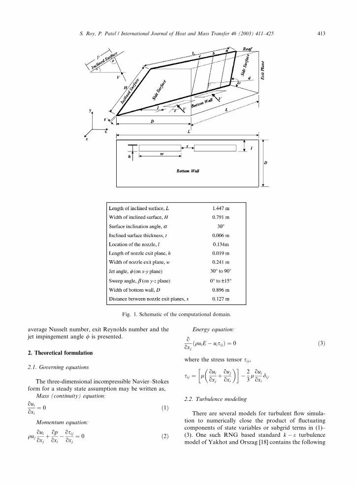
lence intensity (TI) and wall yþ. Fig. 1 describes sche-
matic of the jet, the inclined plane and its association
with the control volume bounded by five other surfaces.
All necessary dimensions are given in the figure. Air jets
are issued at temperature Tj, with streamwise and
crosswise angles (/ and b) from the nozzle exit plane,
through two rectangular openings (h� w) impinging
upon the target plane of thickness t with known material
properties. These openings are centered on the length L
of the bottom wall. The target plane is inclined at an
angle of a. The mean velocity of the jet V depends on the
jet Reynolds number and the hydraulic diameter of the
inlet nozzle. For this geometry, the impingement point,
i.e., the intersection of the jet axis and the inclined sur-
face is at a distance p away from the crotch, p ¼ ðl�ðh=2ÞÞðcos a þ ðsin a= tan /ÞÞ.
Three lines a, b and c with constant z-coordinate
0.3733, 0.5233 and 0.7233 m, respectively, are selected
along the height H of the inclined plane for under-
standing heat transfer process and flow characteristics.
These lines coincide with the plane between the jet and
side surface, axis of the jet, and between the jets. The
horizontal line d with constant y-coordinate of 0.072 m,
starts from the point where the jet axis impinges on
the surface for / ¼ 60� and ends on a point of the exit
plane as shown in Fig. 1. Heat transfer process in the
computational domain is investigated by using a finite
volume based commercial code FLUENT� [17]. The
three-dimensional computational model is analyzed with
renormalized group (RNG) k � e turbulence closure
model of Yakhot and Orszag [18] to understand fluid-
thermal characteristics in jet impingement heat transfer.
Comparison between the local and average Nu on the
surface, and TI and wall yþ distribution at a distance
parallel to the surface are reported for two different
boundary conditions. The correlation between stagna-
tion Nu and Re is presented. Nusselt number, TI and
wall yþ distribution over the inclined surface are com-
pared for eight different Reynolds numbers (Re ¼ 500,
1500, 5000, 7500, 10 000, 12 500, 15 000 and 20 000) for
air (Pr ¼ 0:7). The effect of jet angle on the impingement
heat transfer is also discussed for Reynolds numbers
5000, 10 000 and 20 000. The angle / is varied from 30�to 90� in steps of 15� in the xy-plane and then for
/ ¼ 75�, the sweep angle b is varied from 5� to 15�(outward direction) and �5� to �15� (inward direction)
in the yz-plane. The jet openings are in plane with the
bottom wall for all these experiments. The effect of jet
impingement angle on local and average Nu, TI and wall
yþ is then reported. Finally, a correlation between the
Nomenclature
Ci coefficients
E specific enthalpy
k turbulent kinetic energy
Le characteristic length
p static pressure
Pr Prandtl Number
Sij mean strain tensor
t time
T temperature
Tu turbulence level
ui Cartesian velocity component
us wall shear velocity
xi spatial coordinates
yþ inner variable
Greek symbols
e dissipation rate of turbulent kinetic energy
lt eddy viscosity
l viscosity
q density
sij stress tensor
dij Kronecker delta
Subscripts
avg average
eff effective
in inlet (at nozzle exit)
i, j direction of special derivatives
k mean velocity
stg stagnation condition
s shear stress based variable
w wall
412 S. Roy, P. Patel / International Journal of Heat and Mass Transfer 46 (2003) 411–425
average Nusselt number, exit Reynolds number and the
jet impingement angle / is presented.
2. Theoretical formulation
2.1. Governing equations
The three-dimensional incompressible Navier–Stokes
form for a steady state assumption may be written as,
Mass (continuity) equation:
ouioxi
¼ 0 ð1Þ
Momentum equation:
qujouioxj
þ opoxi
� osijoxj
¼ 0 ð2Þ
Energy equation:
o
oxjðquiE � uisijÞ ¼ 0 ð3Þ
where the stress tensor sij,
sij ¼ louioxj
��þ ouj
oxi
��� 2
3louioxi
dij
2.2. Turbulence modeling
There are several models for turbulent flow simula-
tion to numerically close the product of fluctuating
components of state variables or subgrid terms in (1)–
(3). One such RNG based standard k � e turbulence
model of Yakhot and Orszag [18] contains the following
Fig. 1. Schematic of the computational domain.
S. Roy, P. Patel / International Journal of Heat and Mass Transfer 46 (2003) 411–425 413

two equations, one for turbulence kinetic energy k and
the other for its dissipation rate e, respectively,
o
oxil
��þ lt
Prk
�okoxi
�þ 2ltSij
�� 2
3qkdij
�oujoxi
¼ qe ð4Þ
and
o
oxil
��þ lt
Prk
�oeoxi
�þ C1e
ek
2ltSij
�� 2
3qkdij
�oujoxi
¼ C2eqe2
kð5Þ
In the above equations, the left hand side shows the
diffusion and generation terms and the right hand side
involves dissipation rate terms. The turbulent viscosity is
modeled as lt ¼ Clqk2=e, where Cl ¼ 0:0845 (Lam [19]).
The standard coefficients are C1e ¼ 1:42 and C2e ¼ 1:68.
Accurate computation of the turbulent flow strongly
depends on the local grid generation especially in the
near wall region where the shear layer forms. In this
region, the mesh measure can be computed as,
yþ ¼ qusf ðyÞl
ð6Þ
where the wall shear velocity us ¼ffiffiffiffiffiffiffiffiffiffisw=q
pand f ðyÞ is the
normal distance from the wall.
The turbulent viscosity is not a fluid property, but
rather a property of the flow field. Its value is added to
the molecular viscosity and yields an effective viscosity,
leff , which is used in the computational model. The k
and e at the inlet are calculated from the following ex-
pressions:
kin ¼ 3
2ðTu � uÞ2 ein ¼ k3=2
in
Leð7Þ
where Tu is the turbulence level and Le is a characteristic
length based on the nozzle exit.
Eqs. (1)–(5) constitute a system of non-linear alge-
braic equations. The system is linearized by relaxation.
A second-order accurate streamline upwinding tech-
nique is employed for stabilizing numerical iterations.
The pressure corrections are used to correct the pressure
and the velocities. This predictor-corrector procedure
constitutes an iteration. The solution is declared con-
vergent when the maximum residual for each of the state
variable becomes smaller than a convergence criterion of
2. Here, the convergence of a solution vector U on node
n is defined as the norm:
kUn �Un�1kkUnk
6 2
We selected 2¼ 10�3 for continuity, momentum, tur-
bulence kinetic energy and its dissipation rate equations
and 2¼ 10�6 for the energy equation.
2.3. Boundary conditions
Two different boundary condition cases (A and B)
are utilized to analyze the fluid thermal system. In the
first case, the roof, side walls, bottom wall and back wall
of the control volume are considered as typical wall
boundary conditions. Here onwards, this will be called
�Case A�. In the other, all boundaries except for the in-
clined plane, bottom wall and inlet jets are pressure
outlet i.e. atmospheric pressure boundary condition.
Here onwards, we call this �Case B�. Details of the im-
posed boundary condition for cases A and B are given in
Table 1 (Panels A and B), respectively. The inclined
plane is always considered as no-slip wall where a con-
vective boundary condition with constant temperature
of 273 K and a heat transfer coefficient of 35 W/m2 K is
applied on the outer surface. Air jets are issued at 293 K
from the nozzle exit plane with a plug flow velocity ~VVthat was imposed based on 5006Re6 20000. According
Table 1
Prescribed boundary conditions for Case A (Panel A) and Case B (Panel B)
Boundary U v w T p k e
Panel A
Inclined plate 0 0 0 273K, 35 W/m2 K op=on ¼ 0 ok=on ¼ 0 ew
Nozzle Prescribed uniform profile 293K op=oy ¼ 0 kin ein
Bottom 0 0 0 oT=oy ¼ 0 op=oy ¼ 0 ok=oy ¼ 0 ew
Sides 0 0 0 oT=oz ¼ 0 op=oz ¼ 0 ok=oz ¼ 0 ew
Roof 0 0 0 oT=oy ¼ 0 op=oy ¼ 0 ok=oy ¼ 0 ew
Exit ou=ox ¼ 0 ov=ox ¼ 0 ow=ox ¼ 0 oT=ox ¼ 0 op=ox ¼ 0 ok=ox ¼ 0 oe=ox ¼ 0
Panel B
Inclined plate 0 0 0 273K, 35 W/m2 K op=on ¼ 0 ok=on ¼ 0 ew
Nozzle Prescribed uniform profile 293K op=oy ¼ 0 kin ein
Bottom 0 0 0 oT=oy ¼ 0 op=oy ¼ 0 ok=oy ¼ 0 ew
Sides ou=oz ¼ 0 ov=oz ¼ 0 ow=oz ¼ 0 oT=oz ¼ 0 op=oz ¼ 0 ok=oz ¼ 0 oe=oz ¼ 0
Roof ou=oy ¼ 0 ov=oy ¼ 0 ow=oy ¼ 0 oT=oy ¼ 0 op=oy ¼ 0 ok=oy ¼ 0 oe=oy ¼ 0
Exit ou=ox ¼ 0 ov=ox ¼ 0 ow=ox ¼ 0 oT=ox ¼ 0 op=ox ¼ 0 ok=ox ¼ 0 oe=ox ¼ 0
414 S. Roy, P. Patel / International Journal of Heat and Mass Transfer 46 (2003) 411–425

to the jet impingement angle (/ and b) the u, v and
w components of plug flow velocity ~VV are calculated
and applied at the inlets. Corresponding k and e values
at the inlet are calculated via (7). The nozzle exit is
in plane with the bottom wall for all variations of /and b.
3. Results and discussion
Fig. 1 shows schematic of the computational domain
which has been discretized in to tetrahedral finite vol-
umes using commercial modeling code Hypermesh� 4.0
[20]. The three-dimensional Navier-Stokes equations
(1)–(5) are then solved using Fluent� 5.2 [17] for flow,
energy and turbulence closure. The Nusselt number
distribution on three lines a, b, c in Fig. 1, and TI and yþ
distribution at a normal distance of 0.003 m parallel to
these lines are investigated in this section. Correspond-
ing material properties of the inclined glass surface
and its associated control volume of air are shown in
Table 2.
A mesh independence study of velocity components
plotted for this line d with four different mesh sizes of
97 000 cells, 141 000 cells, 200 000 cells and 246 000 cells,
Fig. 2a–d, established the moderate 200 000 tetrahedral
cells as the optimum mesh. The inlet conditions for this
mesh study were uniform velocity profiles based on Re ¼12500 for both openings. Fig. 2d plots the zoomed-in
comparison of v-velocity near shear layer region dem-
onstrating that nearly grid independent results can be
obtained on the moderate 200 000 cells grid. It should be
noted here, that grid independent solution with respect
to turbulence variables has not been achieved, but the
difference on the results from the moderate and fine
Table 2
Material properties used in the numerical simulation
Air Glass
Density (kg/m3) 1.225 2500
Specific heat (J/kg K) 1006.43 750
Thermal conductivity (W/m K) 0.0242 1.4
Viscosity (kg/m s) 1.7894e�5
Fig. 2. Mesh independence study on line d for Re ¼ 12500 with / ¼ 60� and b ¼ 0�.
S. Roy, P. Patel / International Journal of Heat and Mass Transfer 46 (2003) 411–425 415

mesh is small (less than 3% of moderate solution peak)
and use of any finer mesh would only increase the
computational cost. Hence hereafter, our computational
mesh consists of 200 000 cells.
Fig. 3a describes how the fluid comes out of the
nozzle and impinges upon the surface and divides into
major and minor flows for boundary condition A. Sig-
nificant portion of the incoming fluid attaches the wall
and moves upward eventually going towards down-
stream and creating a recirculation associated with
complex multiple vortex structure in the computational
domain while rest of the incoming fluid creates a smaller
Fig. 3. Simulation results for Re ¼ 20000 with Case A at / ¼ 60� and b ¼ 0�. (a) Velocity vectors plotted on the xy-plane at z ¼ 0:5233
m; (b) speed (m/s) contour on a parallel plane at normal distance of 0.01 m next to inclined wall; (c) static temperature (K) on the inside
of the inclined surface.
416 S. Roy, P. Patel / International Journal of Heat and Mass Transfer 46 (2003) 411–425

wake upstream, towards the crotch (bottom left in Fig.
3a). For Re ¼ 20000, Fig. 3b shows the speed contours
close to the inclined surface at a distance of 0.01 m
demonstrating the stagnation region and shear layers
that affects the fluid flow structure. A pair of turbulent,
incompressible, rectangular jets is impinging on the in-
clined wall. Each jet creates a stagnation zone about the
impingement location, and then spreads in all the di-
rection attaching the wall. The major and minor flows
that follow generate shear layers. Temperature distri-
bution on inclined wall is shown in Fig. 3c that plots
symmetric contour patterns for Re ¼ 20000 with the
highest temperature in the stagnation region where the
jet impinges upon the wall. Near this region the heat
diffusion is dominant. The temperature decreases in the
rest of the wall through convective heat transfer in the
shear layer.
After impingement, each jet creates a pair of counter
rotating vortices in the crosswise direction. It is obvious
that the jet spreads more due to these bound vortices,
covering a larger cross-section. This is the result of the
bound vortices being confined in a smaller space, in-
ducing larger crosswise components of velocity and thus
aiding the spread of the jet. The flow coming out of the
hole in the form of a jet is subjected to bending due to
the impingement and in the process reducing signifi-
cantly the effect of the boundary layer thickness. The
vorticity associated with the wake side of the jet pro-
duces a pair of bound vortices. Fig. 4 documents these
bound vortices created between the jets on the vertical
plane cutting through the inlet jet for Re ¼ 20000 at
x ¼ 0:144 m with / ¼ 60� and b ¼ 0�.Fig. 5 shows particle track from inlet colored by ve-
locity magnitude, based on Re ¼ 20000, in the computa-
tional domain (color figures for this paper are available
at http://meweb.kettering.edu/publications/sroy/ijhmt2.
pdf). For Case A, Fig. 5a shows formation of small
bound vortices in between two rectangular inlet openings
because of large velocity magnitude, while after im-
pingement of the jet with solid surface it creates a smaller
upstream wake and a larger wake in the downstream
region. The three dimensionality of the flow field is
evident. Fig. 5b also shows the same for Case B, but
does not display any three-dimensional flow recirculation
Fig. 4. Velocity vector distribution on the central cutting plane shows strong bound vortices between the jets for Re ¼ 20000 with
/ ¼ 60� and b ¼ 0�.
Fig. 5. Path lines showing the particle tracks in the computational domain with two different boundary conditions for Re ¼ 20000 with
/ ¼ 60� and b ¼ 0�.
S. Roy, P. Patel / International Journal of Heat and Mass Transfer 46 (2003) 411–425 417

except for bound vortices formation on the y–z plane
between the jets.
Inlet TI plays a critical role in identifying the level of
turbulence kinetic energy in the solution domain. Fig. 6
shows TI distribution on lines parallel to a (line z ¼0:3733 m), b (line z ¼ 0:5233 m) and c (line z ¼ 0:7233
m) at a normal distance of 0.003 m for Re ¼ 20000. The
distribution remains high about the stagnation region
showing mean velocity gradient is the highest at that
point and sharply decreases in the nearby region where
the shear layer forms. TI is generally 20% higher for
Case B than for Case A. The non-dimensional yþ is a
function of wall shear stress. Fig. 7 shows the distribu-
tion of wall yþ on the lines parallel to a (line z ¼ 0:3733
m), b (line z ¼ 0:5233 m) and c (line z ¼ 0:7233 m) at a
normal distance of 0.003 m to demonstrate wall shear
stress distribution. The yþ is spatially fluctuating but its
peak is about the stagnation point and decreases slowly
in its nearby region. This means maximum wall shear
stress is being produced at the stagnation point and then
it decays slowly in the nearby region. Moreover,
it is nearly 10% lower for Case B than for Case A,
which demonstrates generation of higher wall shear
stress for Case A than in Case B for the same Reynolds
Number.
Fig. 8 shows the comparison of local Nu distribution
on lines a (line z ¼ 0:3733 m), b (line z ¼ 0:5233 m) and c
(line z ¼ 0:7233 m) for Re ¼ 20000, with boundary
condition cases A and B for the control volume. Nu
distribution gives better idea of jet impingement heat
transfer through the surface. In general, the local Nu for
Case A is about 30% higher than that in Case B. The Nu
peaks at the stagnation point and then decreases in its
nearby region where shear layer forms. A careful ob-
servation of Fig. 8 reveals that the stagnation point is at
a position about 0.12 m away from the crotch, displaced
from the intersection of the jet axis (p ¼ 0:1437 m for
a ¼ 30� and / ¼ 60�) towards the crotch. This is con-
sistent with the reported literature [21]. The discrepancy
is due to the fact that the jets coming out of the opening
are subjected to bound vortices and in the process sig-
nificantly bend downward.
Fig. 6. Comparison of TI distribution parallel to lines a, b, c at
a normal distance 0.003 m near the inclined surface for two
boundary conditions for Re ¼ 20000 with / ¼ 60� and b ¼ 0�:(a) Case A; (b) Case B.
Fig. 7. Comparison of yþ distribution parallel to lines a, b, c at
a normal distance 0.003 m near the inclined surface for two
boundary conditions for Re ¼ 20000 with / ¼ 60� and b ¼ 0�:(a) Case A; (b) Case B.
418 S. Roy, P. Patel / International Journal of Heat and Mass Transfer 46 (2003) 411–425

Fig. 9 shows the trend of average Nusselt number
(Nuavg) on the surface for different Re with boundary
condition cases A and B. The average Nu is computed
on the inside of the inclined surface of area C as:
Nuavg ¼ 1=CZ
CNudC ð8Þ
In general, Nuavg increases as the Re increases. It is also
higher for Case A than for Case B. The jet-vortex in-
teraction appears to have a significant effect on heat
transfer. For all Re, the peak Nusselt number in Case A
is always higher than that for Case B. This is primarily
due to the fact that less energy is lost in Case A than in
B. Also peak Nu increases as Re increases. The trendline
shows for Case A,
Nuavg ¼ 1:54Re0:5962 1:54Re0:6 ð9aÞ
while for Case B, the relationship is
Nuavg ¼ 0:021Re0:9888 0:02Re ð9bÞ
Another important aspect is the stagnation Nusselt
number and its functional relation to the flow parame-
ters. Similar studies have been done by Lonney and
Walse [22] for an isothermal two-dimensional turbulent
jet impinging on a heated flat plate placed at right angle
for different values of Re and height to width ratio of
nozzle outlet plane (h=b). They proposed correlation to
predict stagnation Nusselt number (Nustg) based on two-
dimensional analysis,
Nustg ¼ 1:2Re0:58ðh=bÞ�0:62 � 5%
where 14 < h=b < 60 and 2000 < Re < 50000. In com-
parison, Fig. 10 documents stagnation Nu for different
Re for a pair of laminar and turbulent slot jets impinging
at an angle / ¼ 60� and b ¼ 0� using a three-dimen-
sional model. Based on air (Pr ¼ 0:7), the trendline
shows our proposed correlationship between Nustg and
Re as
Nustg ¼ 11:5Re0:63 ð10Þ
The obvious difference is due to the fact that in [22]
the two-dimensional domain has all sides open bound-
ary condition, and the correlation (10) is found based on
three-dimensional analysis with Case A boundary con-
dition.
Fig. 8. Comparison of Nusselt number distribution on the
surface along lines a, b, c for two boundary conditions for
Re ¼ 20000 with / ¼ 60� and b ¼ 0�: (a) Case A; (b) Case B.
Fig. 9. Effect of boundary condition and flow characteristics on
heat transfer process with / ¼ 60� and b ¼ 0�.Fig. 10. Comparison of Nustg vs Re for Case A and jet angles
/ ¼ 60�, b ¼ 0�.
S. Roy, P. Patel / International Journal of Heat and Mass Transfer 46 (2003) 411–425 419

Fig. 11a–c show local Nusselt number, TI and wall
yþ distribution on line b for different Reynolds numbers
for Case A. Heat transfer is maximum through the shear
layer region as discussed earlier and peak of Nu, TI and
Fig. 11. Effect of Reynolds number on (a) local Nusselt number along b on the inside of the inclined surface; and (b) TI and (c) yþ
distributions at a normal distance of 0.003 m parallel to the incline with / ¼ 60� and b ¼ 0�.
420 S. Roy, P. Patel / International Journal of Heat and Mass Transfer 46 (2003) 411–425

yþ increases as Re increases. The local Nu plot in Fig.
11a for 50006Re6 20000, demonstrates that at the
stagnation point the diffusive heat transfer is dominant
and in its nearby region the convective heat transfer is
dominant because of higher velocity gradient. The TI
plot in Fig. 11b for 50006Re6 20000 shows similar
Fig. 12. Effect of jet angle / on local Nu distribution along line b on the inside of the inclined surface: (a) Re ¼ 5000, (b) Re ¼ 10000
and (c) Re ¼ 20000 with b ¼ 0�.
S. Roy, P. Patel / International Journal of Heat and Mass Transfer 46 (2003) 411–425 421
trend. However, the wall yþ distribution on line b
represents high wall shear beyond the stagnation
point, Fig. 11c. At a normal distance of 0.003 m from
theinclined wall, the spatial fluctuation in yþ distri-
bution for 50006Re6 20000 becomes dominant as
Re increases possibly demonstrating the presence of
the turbulent flow structure along the jet attachment
region.
The angle / is inclination of the jet axis with respect
to the inclined surface in the xy-plane as shown in Fig. 1.
The effect of / on heat transferring through the inclined
wall is reported in Fig. 12a–c by studying the local Nu
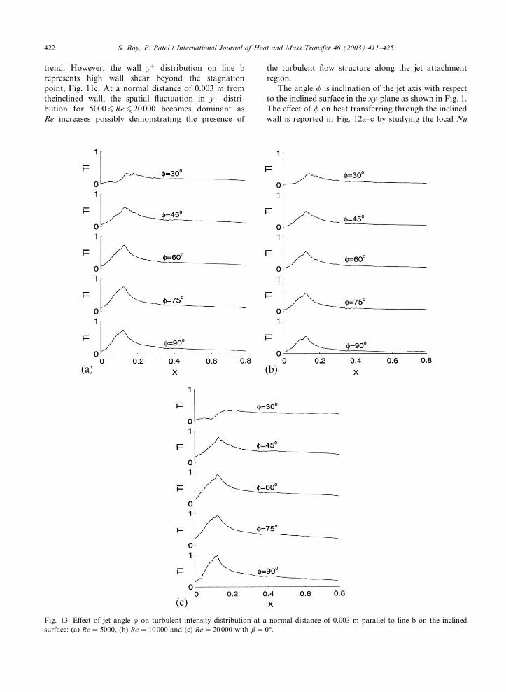
Fig. 13. Effect of jet angle / on turbulent intensity distribution at a normal distance of 0.003 m parallel to line b on the inclined
surface: (a) Re ¼ 5000, (b) Re ¼ 10000 and (c) Re ¼ 20000 with b ¼ 0�.
422 S. Roy, P. Patel / International Journal of Heat and Mass Transfer 46 (2003) 411–425

distribution on line b for Re ¼ 5000, 10 000 and 20 000,
respectively. Clearly, the effect of jet angle is significant
on heat transfer process for any particular Reynolds
number and it is more so for high Re flows as compare
Fig. 14. Effect of jet angle / on yþ distribution at a normal distance of 0.003 m parallel to line b on the incline: (a) Re ¼ 5000, (b)
Re ¼ 10000 and (c) Re ¼ 20000 with b ¼ 0�.
S. Roy, P. Patel / International Journal of Heat and Mass Transfer 46 (2003) 411–425 423

to low. Moreover, the peak of Nu is shifting towards left
because the stagnation point (intersection of the jet axis
and solid wall) is moving downwards as jet angle in-
creases from 30� to 90�. The heat transfer is the maxi-
mum through this stagnation point. It also shows that
the highest value of Nu is attained for / ¼ 75� for all
Reynolds numbers, specifically for high Re ¼ 20000,
Fig. 12c.
Similarly, Fig. 13a–c show effect of jet angle (/) on
TI distribution along line b for Reynolds number 5000,
10 000 and 20 000, respectively. The level of turbulent
kinetic energy is maximum in the shear layer region and
highest at stagnation point which moves towards left as
jet angle increase from 30� to 90�. Fig. 13a–c plot the
wall yþ distribution as a function of / for Re ¼ 5000,
10 000 and 20 000, respectively. For Re ¼ 5000 in Fig.
14a, the benign yþ distribution shows less presence of
turbulence. As the Re increases from 10 000 (Fig. 14b) to
20 000 (Fig. 14c), the wall shear becomes dominant
clearly demonstrating the presence of turbulent flow
structures along the jet attachment region. The distri-
bution of the wall shear however varies as the jet angle /increases from 30� to 90�.
Fig. 15 shows the effect of jet angle (/) on average of
Nu computed via (8) on the entire inclined surface for
Reynolds number 5000, 10 000 and 20 000 with Case A
boundary condition and b ¼ 0�. Based on curve fitting
the following correlation of average Nu, Re and jet angle
/ may be derived:
Nuavg ¼ A/2 þ B/ þ C ð11Þ
where A ¼ �ð0:0436Re2 þ 0:021Re þ 0:0081Þ, B ¼ð5:56Re2 þ 2:77Re þ 2:45Þ, and C ¼ �ð103:2Re2 þ140:4Re � 130:8Þ.
The effect of jet angle / on heat transfer through the
solid wall is more for high Re as compared to low Re.
Numerical results for five different / values (30�, 45�,60�, 75� and 90�) show significant change in the heat
transfer process as / changes. Specifically, for a partic-
ular Re ¼ 20000, the average Nusselt number varies
from 187 at / ¼ 30� to 775 at / ¼ 75�. For this geo-
metric configuration, the plot predicts the highest Nuavg
of �800 at / ¼ 70�. This contradicts the traditional
understanding [21,22] that Nuavg should occur when the
jet is normal to the wall, i.e., at / ¼ 60�. This shift is due
to bound vortices that bend the impinging jet and the
close proximity of the wall boundaries and the small
crotch angle a.
The angle b is inclination of jet axis in yz-plane as
shown in Fig. 1. Jet angle b is varied from 5� to 15�(outward direction) and �5� to �15� (inward direction)
in the yz-plane while / is maintained at 75�. Fig. 16
documents the effect of b on Nuavg. Increasing b in the
inward direction reduces heat transfer for all Re. For
lower Re, increasing b in the outward direction slightly
improves the Nuavg. However, for Re ¼ 20000, Nuavg
sharply decreases as b is increased beyond 5�.
4. Conclusions
Jet impingement heat transfer and flow characteris-
tics for two rectangular jets impinging upon an inclined
surface have been studied with the following conclu-
sions. Heat transfer is the maximum through the shear
layer formed near the jet attachment stagnation region.
The peak Nusselt number is always higher in Case A
than in Case B for a particular inlet Reynolds number.
This is primarily due to the fact that more energy is
convected out through the openings in the latter case.
Turbulence (velocity gradient) and wall shear force is
higher in the shear layer region and the peak increases
with the inlet Reynolds number. Documented correla-
tions between Re and Nuavg for both boundary condi-
tions show that average Nu on the inside of the inclined
surface increases as Re and/or Pr increases. Changing jet
angle significantly affects the heat transfer process near
the inclined surface. Specifically, increasing the jet im-Fig. 15. Effect of jet angle / on the non-dimensional heat
transfer coefficient Nuavg with b ¼ 0�.
Fig. 16. Effect of jet angle b on the non-dimensional heat
transfer coefficient Nuavg with / ¼ 75�.
424 S. Roy, P. Patel / International Journal of Heat and Mass Transfer 46 (2003) 411–425

pingement angle / can improve the Nuavg by nearly four
times for Re ¼ 20000. For this geometric configuration
resembling a vehicle windshield, an optimum / exists for
maximum heat transfer. However, increasing b reduces
the heat transfer. The stagnation Nu has been correlated
for the boundary condition of Case A that is substan-
tially different than the previously reported Nustg for
boundary condition similar to Case B. Finally, a corre-
lation between Nuavg, / and Re has been presented.
Acknowledgements
This work was partially supported by NASA grant
nos. NAG3-2520 and NAG3-2638 with D. Jacobson
and D.R. Reddy as technical monitors, respectively.
References
[1] P.J. Lamont, B.L. Hunt, The impingement of under
expanded, axisymmetric jets on perpendicular and inclined
plates, J. Fluid Mech. 100 (3) (1980) 471–511.
[2] A. Benard, L.E. Brizzi, J.L. Bousgarbies, Study of several
jets impinging on a plane wall: visualizations and laser
velocimetry investigations, J. Fluid Eng. 121 (1999) 808–
812.
[3] S. Polat, B. Huang, A.S. Mujumdar, W.J.M. Douglas,
Numerical flow and heat transfer under impinging jets: a
review, Ann. Rev. Numer. Fluid Mech. Heat Transfer 2
(1989) 157–197.
[4] H. Martin, Heat and mass transfer between impinging jets
and solid surfaces, Adv. Turbulence 2 (1977) 37–44.
[5] S.J. Downs, E.H. James, Jet impingement heat transfer––a
literature survey, ASME paper no. 87-HT-35 (1987).
[6] S.J. Lee, J.H. Lee, D.H. Lee, Local heat transfer measure-
ments from an elliptical jet impinging on a flat plate using
liquid crystal, Int. J. Heat Mass Transfer 37 (6) (1994) 967–
976.
[7] S.C. Arjocu, J.A. Liburdy, Identification of dominant heat
transfer modes associated with the impingement of an
elliptical jet array, J. Heat Transfer 122 (2000) 240–247.
[8] H. Martin, Heat and mass transfer between impinging gas
jets and solid surfaces, in: Advances in Heat Transfer, vol.
13, Academic Press, New York, 1977, pp. 1–60.
[9] D.W. Colucci, R. Viskanta, Effect of nozzle geometry on
local convective heat transfer to a confined impinging air
jet, Exp. Thermal Fluid Sci. 13 (1996) 71–80.
[10] Y. Pan, B.W. Webb, Visualization of local heat transfer
under arrays of free-surface liquid jets, Proc. Tenth Int.
Heat Transfer Conf. 4 (1994) 77–82.
[11] D.E. Metzger, K.N. Cummings, W.A. Ruby, Effects of
Prandtl number on heat transfer characteristics of imping-
ing liquid jets, Proc. Fifth Int. Heat Transfer Conf. 2 (1974)
20–24.
[12] M.M. Rahman, A.J. Bulla, J.E. Leland, Numerical model
of conjugate heat transfer during free liquid jet impinge-
ment, Proc. ASME, AES 38 (1998) 475–486.
[13] J.E. Leland, M.R. Pais, Free jet impingement heat transfer
of a high Prandtl number fluid under conditions of highly
varying properties, J. Heat Transfer 121 (1999) 592–597.
[14] G.K. Morris, S.V. Garimella, R.S. Amano, Prediction of
jet impingement heat transfer using a hybrid wall treatment
with different turbulent Prandtl number functions, J. Heat
Transfer 118 (1996) 562–568.
[15] S. Roy, K. Nasr, P. Patel, B. Abdulnour, Rectangular jet
impingement heat transfer on a vehicle windshield, AIAA
J. Thermophys. Heat Transfer 16 (1) (2002) 154–157.
[16] S. Roy, K. Nasr, P. Patel, B. Abdulnour, An experimental
and numerical study of heat transfer off an inclined surface
subject to an impinging airflow, Int. J. Heat Mass Transfer
45 (8) (2002) 1615–1629.
[17] FLUENT� 5 User�s guide, Fluent Inc., Lebanon, NH 1-4
(1998).
[18] V. Yakhot, S.A. Orszag, Renormalization group analysis
of turbulence. I. Basic theory, J. Sci. Comput. (1986) 3–51.
[19] S.H. Lam, On the RNG theory of turbulence, Phys. Fluids
A 4 (1992) 1007–1017.
[20] Hyperworks� 4.0 Online users manual, Altair Engineering,
Troy, MI (2000).
[21] X. Yan, N. Saniei, Heat transfer from an obliquely
impinging circular air jet to a flat plate, Int. J. Heat Fluid
Flow 18 (1997) 591–599.
[22] M.K. Lonney, J.J. Walse, Mean-flow and turbulent char-
acteristics of free and impinging jet flows, J. Fluid Mech.
147 (1984) 397–429.
S. Roy, P. Patel / International Journal of Heat and Mass Transfer 46 (2003) 411–425 425


![REPORTOOCUM ETATIONPAOB - DTICcharacteristics of impinging jet sprays. Ingebo [6] quantified the drop-size distribution for heptane jets impinging at 90%, and obtained an empirical](https://static.fdocuments.in/doc/165x107/5f7eb6364693594f354d769d/reportoocum-etationpaob-dtic-characteristics-of-impinging-jet-sprays-ingebo-6.jpg)