Protecting EHV Transmission Lines Using Ultra-High-Speed ...
International Research Journal of Engineering and Technology (IRJET) e-ISSN: 2395 -0056
Volume: 02 Issue: 09 | Dec-2015 www.irjet.net p-ISSN: 2395-0072
© 2015, IRJET ISO 9001:2008 Certified Journal Page 921
Study of Different Aspects for Designing of Ultra High Voltage
Transmission Line
Mohammad Imran1, Mohammad Nasim2, Ankur Paul3
1 Assistant Professor, Electrical Engineering, Jahangirabad Educational Trust Group of Institution Faculty of Engineering Barabanki (U.P.), India
2 Assistant Professor, Electrical Engineering, Integral University, U.P., India 3 Senior Officers, Quality Management, NASRAC, Lucknow, U.P., India
---------------------------------------------------------------------***---------------------------------------------------------------------Abstract Power consumption per capita increases
day by day. So a cost effective and highly efficient
transmission system is needed. Hydro-electric and coal
or oil-fired stations are located far away from load
centers for various reasons. It requires the
transmission of the generated electric power over very
long distances. In this paper we have studied a different
aspect like voltage selection, selection of insulation and
mechanical designing. For the transmission purpose we
need high voltage, EHV and UHV. For the transmission
at these voltage levels we need a strong structure to
hold the conductors, insulators and ground wires.
Key Words: Electrical Multiple Unit, Extra High
Voltage, Ultra High Voltage
1. ROLE OF EHV AC TRANSMISSION
Industrial-minded countries of the world require a vast amount of energy of which electrical energy forms a major fraction. There are other types of energy such as oil for transportation and industry, natural gas for domestic and industrial consumption, which form a considerable proportion of the total energy consumption[1]. Thus, electrical energy does not represent the only form in which energy is consumed but an important part nevertheless. It is only 150 years since the invention of the dynamo by Faraday and 120 years since the installation of the first central station by Edison using dc. But the world has already consumed major portion of its natural resources in this short period and is looking for sources of energy other than hydro and thermal to cater for the rapid rate of consumption which is outpacing the discovery of new resources[2]. This will not slow down with time and therefore there exists a need to reduce the rate of annual increase in energy consumption by any intelligent society if resources have to be preserved for posterity. After the end of the Second World War, countries all over the world have become independent and are showing a tremendous rate of industrial development, mostly on the lines of
North-American and European countries, the U.S.S.R. and Japan. Therefore, the need for energy is very urgent in these developing countries, and national policies and their relation to other countries are sometimes based on energy requirements, chiefly nuclear.
Hydro-electric and coal or oil-fired stations are located very far from load centers for various reasons which requires the transmission of the generated electric power over very long distances[3].
This requires very high voltages for transmission. The very rapid strides taken by development of dc transmission since 1950 are playing a major role in extra-long-distance transmission, complementing or supplementing E.H.V. ac transmission. They have their roles to play and a country must make intelligent assessment of both in order to decide which is best suited for the country's economy. This book concerns itself with problems of E.H.V. ac transmission only.
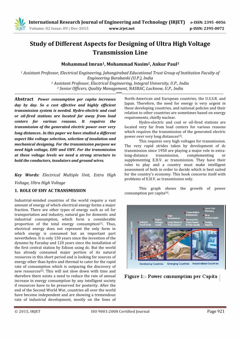
This graph shows the growth of power
consumption per capita[4].
International Research Journal of Engineering and Technology (IRJET) e-ISSN: 2395 -0056
Volume: 02 Issue: 09 | Dec-2015 www.irjet.net p-ISSN: 2395-0072
© 2015, IRJET ISO 9001:2008 Certified Journal Page 922
Table:1: Comparative cost of transmission as ‘cost per mile’ The transmission cost is described above in the tabulated form. We can observed the transmission cost increases rapidly after it crosses the 500 km range[5].
1.1 BRIEF DESCRIPTION OF ENERGY SOURCES AND THEIR DEVELOPMENT Any engineer interested in electrical power transmission must concern himself or herself with energy problems[6]. Electrical energy sources for industrial and domestic use can be divided into two broad categories: (1) Transportable; and (2) Locally Usable. Transportable type is obviously hydro-electric and conventional thermal power. But locally generated and usable power is by far more numerous and exotic. Several countries, including India, have adopted national policies to investigate and develop them, earmarking vast sums of money in their multi-year plans to accelerate the rate of development. These are also called 'Alternative Sources of Power'. Twelve such sources of electric power are listed here, but there are others also which the reader will do well to research.
1.2 Locally Usable Power (1) Conventional thermal power in urban load centers; (2) Micro-hydel power stations; (3) Nuclear Thermal: Fission and Fusion; (4) Wind Energy; (5) Ocean Energy: (a) Tidal Power, (b) Wave Power, and (c) Ocean thermal gradient power; (6) Solar thermal; (7) Solar cells, or photo-voltaic power; (8) Geo-thermal; (9) Magneto hydro-dynamic or fluid dynamic; (10) Coal gasification and liquefaction; (11) Hydrogen power; and last but not least, (12) Biomass Energy: (a) Forests; (b) Vegetation; and (c) Animal refuse.
2. VOLTAGE SELECTION 2.1 STANDARD TRANSMISSION VOLTAGES
Voltages adopted for transmission of bulk power have to
conform to standard specifications formulated in all
countries and internationally. They are necessary in view
of import, export, and domestic manufacture and use. The
following voltage levels are recognized in India as per IS-
2026 for line-to-line voltages of 132 kV and higher[7].
Nominal system voltage
(kV)
132 220 275 345 400 500 750
Maximum Operating
Voltage(kV) 145 245 300 362 420 525 765
Table:2.1: Different system and different operating voltage The voltage selection is basically based on the power
handling capacity of the line. Also there is an empirical
formula to calculate the voltage level. The formula is
VL =5.5√((L/1.6)+((P*1000)/(cosΦ*NC*150)))
Where,
VL = Transmission line voltage in kV
L = Length of the line in Kms = 200 km
P = Power to be transmitted = 1000 MW
NC = Number of circuits
VL= 477.8 KV
But since we use bundled conductors this formula does
not meet our requirements. Therefore we will go
according to the power handling capacity and line loss.
According to the above criteria, the power-handling
capacity of a single circuit is P = E2 sin δ /Lx. At unity
power factor, at the load P, the current flowing is
I = E sin δ / 3 Lx
and the total power loss in the 3-phases will amount to
p = 3I2rL = E2. sin2δ .r/Lx2

International Research Journal of Engineering and Technology (IRJET) e-ISSN: 2395 -0056
Volume: 02 Issue: 09 | Dec-2015 www.irjet.net p-ISSN: 2395-0072
© 2015, IRJET ISO 9001:2008 Certified Journal Page 923
Therefore, the percentage power loss is
% p = 100 p/P = 100. sin δ .(r/x)
Table shows the percentage power loss and power-handling capacity of lines at various voltage levels shown, for δ = 30° and without series-capacitor compensation. Table 2.2. Percent Power Loss and Power-Handling Capacity
With equal voltage magnitudes at both ends to commence the design and 30° phase difference between them, the power-handling capacity per circuit is with x = 0.327 ohm/km.
P = 0.5 × 4002/0.327 × 200 = 1223 MW
Therefore power handling capacity is greater than our requirement, so we choose 400 kV SINGLE CIRCUIT LINE. CAPABILITY CURVE
Fig -1: Capability Curve
DESIGN OF INSULATION
Insulation designing is one of the key aspects of EHV transmission because the cost of the transmission system is dependent largely on insulation. The selection of insulation depends on internal and external voltage. However in the recent advancement in the field of circuit breaker and protective devices the level of insulation levels reduced by a considerable margin. Also earthing plays an important part. System over voltage is an important factor in selection of insulation. Reduction in insulation causes large swing and reduced costing. In EHV transmission system following types of over voltages used to come :-
a) Over voltage due to switching surges.
b) Power frequency over voltages.
c) Over voltages due to direct strokes of lightning.
Switching Over voltages:-
Over voltages due to switching surges are of an internal
origin and are generally oscillatory in nature. These over
voltages are of a short duration and are generally caused
by the following switching operations.
1) “Switching- off” of long lines on no load.
2) Interruption of low inductive current such as the
transformer magnetizing currents.
3) Energizing lines of no load.
4) Clearance of short circuits.
Switching-surge over-voltages as observed on EHV systems of typical configurations. These studies are carried out by three methods: (a) Mathematical modeling using the Digital Computer, (b) Physical modeling using the Transient Network Analyzer (TNA), and (c) Field Tests. Choice of Insulator:-
Insulation designing is one of the key aspects of EHV transmission because the cost of the transmission system is dependent largely on insulation. Economy and practicability of design demand that the insulation should be able to deal with the transient voltages occur in the system. One must strike a balance between the chances of failure and the cost of greater insulation strength.

International Research Journal of Engineering and Technology (IRJET) e-ISSN: 2395 -0056
Volume: 02 Issue: 09 | Dec-2015 www.irjet.net p-ISSN: 2395-0072
© 2015, IRJET ISO 9001:2008 Certified Journal Page 924
There are three types of insulators used for overhead lines.
Pin type insulator Suspension type insulator Strain or tension type insulator
Pin Type Insulator:- As the name suggests, the pin-type insulator is attached to a steel bolt or pin, which is secured to a cross-arm on the transmission pole. The above-mentioned British Standards Specification requires that the porcelain shall not engage directly with a hard metal screw. B.S. 137 recognizes two methods:
1. The provision of a taper thread cut on the head of the pin, which screws into a threaded soft metal thimble cemented into the insulator.
2. The provisions of a cast lead thread on the steel spindle, which screws directly into a thread formed in the porcelain; on the continent the pin, which has a plain top, is still sometimes wrapped in hemp and the threaded porcelain screwed on.
Suspension Type Insulators:-
We have seen that the cost of pin-type insulator increases very rapidly as the working voltage is increased. For high voltages this type is therefore uneconomical, and there is the further disadvantage that replacements are expensive. For these reasons, high-voltage lines are insulated by means of suspension insulators in which, as their name indicates, the line conductor is suspended below the point of support by means of the insulator or insulators. Several important advantages follow from this system.
Each insulator is designed for a comparatively low working voltage, usually about 11,000 volts, and the insulation for any required line voltage can be obtained by using a 'string' of a suitable number of such insulators.
In the event of a failure of an insulator, one unit - instead of the whole string - has to be replaced.
The mechanical stresses are reduced, since the line is suspended flexibly; with pin-type insulators, the rigid nature of the attachment results in fatigue and ultimate brittleness of the wire, due to the alternating nature of the stress. Also, since the string is free to swing, there is an equalization of the tensions in the conductors of successive spans.
In the event of an increase in the operating voltage of the line, this can be met by adding the
requisite number of units to each string, instead of replacing all insulators, as would be necessary with pin-type.
Strain Insulators:-These insulators are used to take the tension of the conductors at line terminals and at points where the line is dead-ended, as for example some road-crossings, junctions of overhead lines with cables, river crossings, at angle towers where there is a change in direction of the line, and so on. For light low-voltage lines, say up to 11,000 volts, the shackle insulator is suitable, but for higher voltages a string of suspension-type insulators is necessary. Where the tension is exceedingly high, as at long river spans, two, three, or even four strings of insulators in parallel have been used. However, the present practice in this country is to avoid the use of multiple strings where heavy mechanical loads are required, and to use units of higher mechanical rating. Standard units are made for 4,000, 8,000, and 12,000 lbs. maximum working load, which suffice for all normal construction on lines up to 275 kV. For river crossings, it is necessary to use multiple strings.
It will be realized that when used as strain insulators, the discs are in a vertical instead of a horizontal plane. This may make some difference to the spark-over voltage [when] wet, the value for the standard ten-inch insulator being 55,000, and for the standard six-inch Hewlett insulator 33,000 volts.
Table:1:Doultons insulation characteristic
Switching Surge Over Voltage Factors:-
System voltage= 400 kv
1. Highest crest voltage= 1.10 х system voltage (for 220 kv.)

International Research Journal of Engineering and Technology (IRJET) e-ISSN: 2395 -0056
Volume: 02 Issue: 09 | Dec-2015 www.irjet.net p-ISSN: 2395-0072
© 2015, IRJET ISO 9001:2008 Certified Journal Page 925
= 1.05 х system voltage (for 400 kv.) =420 kv.
2. Crest factor = 1.414 3. Switching surge strength = 2 (for 400 kv.) 4. Impulse flashover voltage= 1.15 5. Contaminated surface, non-standard condition
=1.1
6. Overall factor of safety= 1.15 +ve impulse flashover voltage (crest 1.2/50μsec.) = vpm х 1.414 х 2х1.5 х 1.15х 1.15 х1.1 =1424.9 kv (for 400 kv, vpm = 6.17)
Corresponding to this voltage the number of discs required= 23 units.
Power Frequency(50 Hz.) Over Voltage Factors:-
System voltage= 400 kv
1. Highest crest voltage= 1.10 х system voltage (for 220 kv.)
= 1.05 х system voltage (for 400 kv.)
=420 kv. 2. Over voltage factor = 1.5 3. Flashover voltage = 1.15 4. Non-standard atmospheric condition,
contaminated surface= 1.2 5. Over all safety margin = vpn х1.05 х1.5 х
1.2х1.5х1.15 = 3.26х 400/√3 = 753 kv.
Corresponding to this voltage the number of discs required= 23 units
Fig:2: Characteristic of Power Frequency Over Voltage Curve
Power Frequency Over Voltages:-
Power-frequency voltage is impressed on a system continuously as compared to transients caused by faults, lightning, and switching operations. Certain abnormal conditions arise when over voltages of a sustained nature can exist in systems which have to be guarded against. Insulation levels will be governed by these, and it is very important to know all the factors which contribute to such over voltages. U.H.V. lines are longer than and their surge impedance lower than lines at 345 kV and lower voltages. Also, EHV lines are used more for point-to point transmission so that when load is dropped, a large portion of the system is unloaded and voltage rise could be more severe than when there is a vast interconnected network. Due also to the high capacitance of UHV lines possibility of self-excitation of generators is quite serious. Shunt reactors are employed to compensate the high charging current, which not only prevent over voltages during load dropping but also improve conditions for load flow, and the risk of self-excitation can also be counteracted. In order to improve conditions, variable static VAR systems can also be employed as well as switched capacitors which introduce harmonics into the system. Finally, the use of series capacitors to increase line loading in long lines might bring about the danger of sub synchronous resonance in which electrical conditions in generators can produce torques which correspond to the torsional frequencies of the shaft and result in mechanical damage.
The system at power frequency consists of lumped-parameter network elements connected to distributed-parameter transmission lines, and the calculations are best handled through generalized constants in matrix form.
In practical line sections of the range 300-500 Km. in length which is usual at 220 Kv. And 400 kv. Increase in voltage during dropping of load does not exceed 1.3 to 1.5 times the maximum normal phase to neutral voltage (rms). The value of these over voltages in practice does not depend on the operating voltage but depends only on the length of the line and the number of lines terminating at or emanating from a station.
International Research Journal of Engineering and Technology (IRJET) e-ISSN: 2395 -0056
Volume: 02 Issue: 09 | Dec-2015 www.irjet.net p-ISSN: 2395-0072
© 2015, IRJET ISO 9001:2008 Certified Journal Page 926
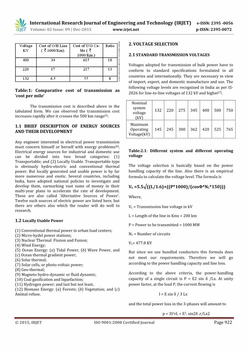
Table -2: chart showing the string efficiency
3. CONCLUSIONS The purpose of study for the selection of insulation is an important aspect in any designing of Extra High Voltage or Ultra High Voltage power system. Also safe operation and cost effective operation is also important. Due to very high voltage it is very highly risky to work or transmit without proper insulation.
ACKNOWLEDGEMENT I would like to thank my family members, my colleagues and the director of the institution for their valuable support in the completion of this paper.
REFERENCES [1] FACTS overview, IEEE and cigre catalog NR95, TP
108. [2] W. Tan, “Tuning of PID load frequency controller for
power systems. “Energy Convers. Manage”.,vol. 50, no. 6, pp. 1465-1472, June. 2009
[3] Transmission Line, Electric Power Research Institute, Second Edition, 1982.
[4] UPSEB statistics at a glance MARCH 1998. [5] Ashfaq Husain ‘Electrical Power System’ Edition
2004, Dhanpat Rai & Co. (Pvt.) Ltd. [6] ‘Different Voltage Selection Criteria And Insulation
Design for a Transmission Line for HV, EHV & UHV System.’ IJATER, Akhlaque khan, Volume 2 May 2012.
[7] Wadhawa C L ‘Elements of Power System’ New Age international 2009.
[8] Modern power system Analysis ”Nagrath & Kothari” 2004.
[9] Manual for designing of transmission lines UPPCL. 2008.
[10] H P Young ‘Electrical Power System Control’ edition 3 Chapman & Hall 1950.
[11] W. D. Stevenson ‘ Elements of Power System Analysis’ fourth edition Tata McGraw Hill, New York, 1980
[12] Hadi Saadat, Power System Analysis, Third edition June 2010.
BIOGRAPHIES
Mohammad Imran was born on 06 July 1987 in Obra Sonebhadra Uttar Pradesh India. Completed his B.Tech & M.Tech. in Engineering from Integral University Lucknow. Working In JETGI since Feb 2012.
Mohammad Nasim was born on 17 jul 1981 at balrampur U.P India. He is working as A.P. in Integral University since 02/07/2012
Ankur Paul born on 06 april 1987 at Lucknow completed his B.Tech. & M.Tech. from integral University.