Study of demagnetization risk for a 12 kW direct driven ...678837/FULLTEXT01.pdf · RESEARCH...
7
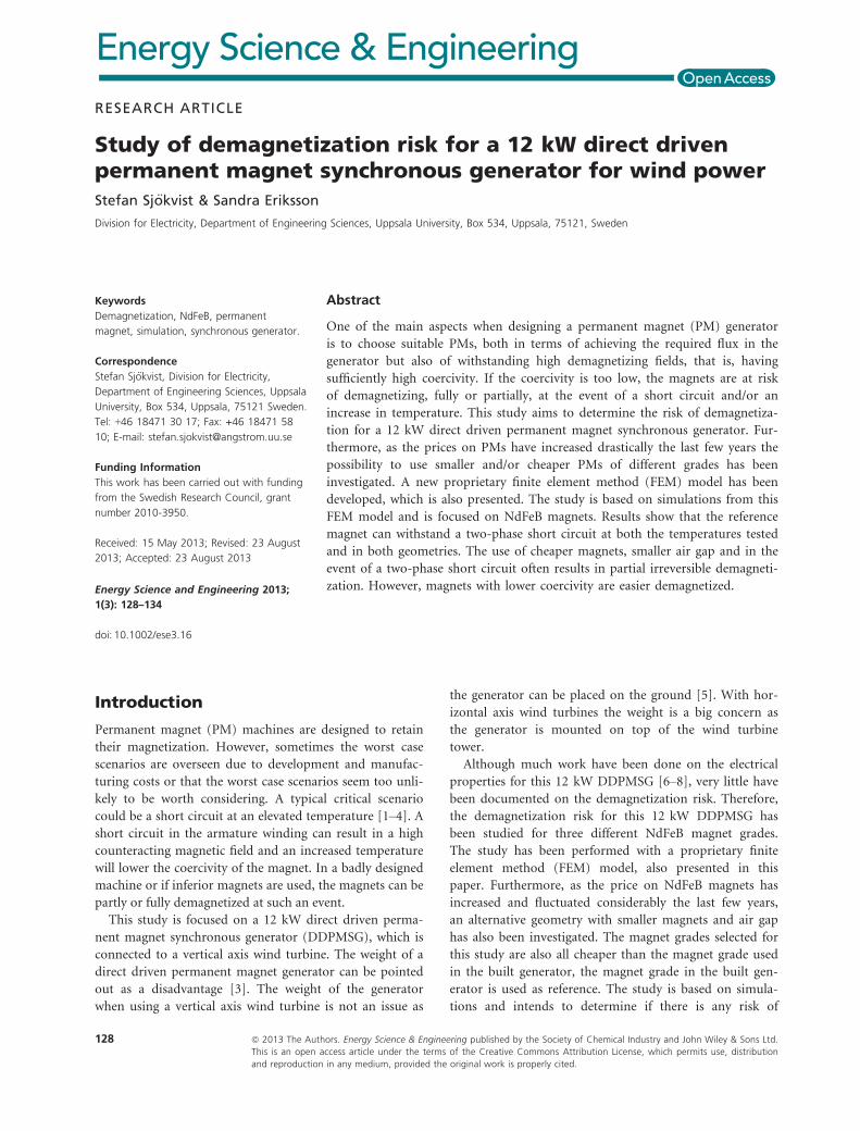
RESEARCH ARTICLE Study of demagnetization risk for a 12 kW direct driven permanent magnet synchronous generator for wind power Stefan Sj € okvist & Sandra Eriksson Division for Electricity, Department of Engineering Sciences, Uppsala University, Box 534, Uppsala, 75121, Sweden Keywords Demagnetization, NdFeB, permanent magnet, simulation, synchronous generator. Correspondence Stefan Sj€ okvist, Division for Electricity, Department of Engineering Sciences, Uppsala University, Box 534, Uppsala, 75121 Sweden. Tel: +46 18471 30 17; Fax: +46 18471 58 10; E-mail: [email protected] Funding Information This work has been carried out with funding from the Swedish Research Council, grant number 2010-3950. Received: 15 May 2013; Revised: 23 August 2013; Accepted: 23 August 2013 Energy Science and Engineering 2013; 1(3): 128–134 doi: 10.1002/ese3.16 Abstract One of the main aspects when designing a permanent magnet (PM) generator is to choose suitable PMs, both in terms of achieving the required flux in the generator but also of withstanding high demagnetizing fields, that is, having sufficiently high coercivity. If the coercivity is too low, the magnets are at risk of demagnetizing, fully or partially, at the event of a short circuit and/or an increase in temperature. This study aims to determine the risk of demagnetiza- tion for a 12 kW direct driven permanent magnet synchronous generator. Fur- thermore, as the prices on PMs have increased drastically the last few years the possibility to use smaller and/or cheaper PMs of different grades has been investigated. A new proprietary finite element method (FEM) model has been developed, which is also presented. The study is based on simulations from this FEM model and is focused on NdFeB magnets. Results show that the reference magnet can withstand a two-phase short circuit at both the temperatures tested and in both geometries. The use of cheaper magnets, smaller air gap and in the event of a two-phase short circuit often results in partial irreversible demagneti- zation. However, magnets with lower coercivity are easier demagnetized. Introduction Permanent magnet (PM) machines are designed to retain their magnetization. However, sometimes the worst case scenarios are overseen due to development and manufac- turing costs or that the worst case scenarios seem too unli- kely to be worth considering. A typical critical scenario could be a short circuit at an elevated temperature [1–4]. A short circuit in the armature winding can result in a high counteracting magnetic field and an increased temperature will lower the coercivity of the magnet. In a badly designed machine or if inferior magnets are used, the magnets can be partly or fully demagnetized at such an event. This study is focused on a 12 kW direct driven perma- nent magnet synchronous generator (DDPMSG), which is connected to a vertical axis wind turbine. The weight of a direct driven permanent magnet generator can be pointed out as a disadvantage [3]. The weight of the generator when using a vertical axis wind turbine is not an issue as the generator can be placed on the ground [5]. With hor- izontal axis wind turbines the weight is a big concern as the generator is mounted on top of the wind turbine tower. Although much work have been done on the electrical properties for this 12 kW DDPMSG [6–8], very little have been documented on the demagnetization risk. Therefore, the demagnetization risk for this 12 kW DDPMSG has been studied for three different NdFeB magnet grades. The study has been performed with a proprietary finite element method (FEM) model, also presented in this paper. Furthermore, as the price on NdFeB magnets has increased and fluctuated considerably the last few years, an alternative geometry with smaller magnets and air gap has also been investigated. The magnet grades selected for this study are also all cheaper than the magnet grade used in the built generator, the magnet grade in the built gen- erator is used as reference. The study is based on simula- tions and intends to determine if there is any risk of 128 ª 2013 The Authors. Energy Science & Engineering published by the Society of Chemical Industry and John Wiley & Sons Ltd. This is an open access article under the terms of the Creative Commons Attribution License, which permits use, distribution and reproduction in any medium, provided the original work is properly cited.
-
Upload
phungthien -
Category
Documents
-
view
214 -
download
0
Transcript of Study of demagnetization risk for a 12 kW direct driven ...678837/FULLTEXT01.pdf · RESEARCH...
RESEARCH ARTICLE
Study of demagnetization risk for a 12 kW direct drivenpermanent magnet synchronous generator for wind powerStefan Sj€okvist & Sandra Eriksson
Division for Electricity, Department of Engineering Sciences, Uppsala University, Box 534, Uppsala, 75121, Sweden
Keywords
Demagnetization, NdFeB, permanent
magnet, simulation, synchronous generator.
Correspondence
Stefan Sj€okvist, Division for Electricity,
Department of Engineering Sciences, Uppsala
University, Box 534, Uppsala, 75121 Sweden.
Tel: +46 18471 30 17; Fax: +46 18471 58
10; E-mail: [email protected]
Funding Information
This work has been carried out with funding
from the Swedish Research Council, grant
number 2010-3950.
Received: 15 May 2013; Revised: 23 August
2013; Accepted: 23 August 2013
Energy Science and Engineering 2013;
1(3): 128–134
doi: 10.1002/ese3.16
Abstract
One of the main aspects when designing a permanent magnet (PM) generator
is to choose suitable PMs, both in terms of achieving the required flux in the
generator but also of withstanding high demagnetizing fields, that is, having
sufficiently high coercivity. If the coercivity is too low, the magnets are at risk
of demagnetizing, fully or partially, at the event of a short circuit and/or an
increase in temperature. This study aims to determine the risk of demagnetiza-
tion for a 12 kW direct driven permanent magnet synchronous generator. Fur-
thermore, as the prices on PMs have increased drastically the last few years the
possibility to use smaller and/or cheaper PMs of different grades has been
investigated. A new proprietary finite element method (FEM) model has been
developed, which is also presented. The study is based on simulations from this
FEM model and is focused on NdFeB magnets. Results show that the reference
magnet can withstand a two-phase short circuit at both the temperatures tested
and in both geometries. The use of cheaper magnets, smaller air gap and in the
event of a two-phase short circuit often results in partial irreversible demagneti-
zation. However, magnets with lower coercivity are easier demagnetized.
Introduction
Permanent magnet (PM) machines are designed to retain
their magnetization. However, sometimes the worst case
scenarios are overseen due to development and manufac-
turing costs or that the worst case scenarios seem too unli-
kely to be worth considering. A typical critical scenario
could be a short circuit at an elevated temperature [1–4]. Ashort circuit in the armature winding can result in a high
counteracting magnetic field and an increased temperature
will lower the coercivity of the magnet. In a badly designed
machine or if inferior magnets are used, the magnets can be
partly or fully demagnetized at such an event.
This study is focused on a 12 kW direct driven perma-
nent magnet synchronous generator (DDPMSG), which is
connected to a vertical axis wind turbine. The weight of a
direct driven permanent magnet generator can be pointed
out as a disadvantage [3]. The weight of the generator
when using a vertical axis wind turbine is not an issue as
the generator can be placed on the ground [5]. With hor-
izontal axis wind turbines the weight is a big concern as
the generator is mounted on top of the wind turbine
tower.
Although much work have been done on the electrical
properties for this 12 kW DDPMSG [6–8], very little have
been documented on the demagnetization risk. Therefore,
the demagnetization risk for this 12 kW DDPMSG has
been studied for three different NdFeB magnet grades.
The study has been performed with a proprietary finite
element method (FEM) model, also presented in this
paper. Furthermore, as the price on NdFeB magnets has
increased and fluctuated considerably the last few years,
an alternative geometry with smaller magnets and air gap
has also been investigated. The magnet grades selected for
this study are also all cheaper than the magnet grade used
in the built generator, the magnet grade in the built gen-
erator is used as reference. The study is based on simula-
tions and intends to determine if there is any risk of
128 ª 2013 The Authors. Energy Science & Engineering published by the Society of Chemical Industry and John Wiley & Sons Ltd.
This is an open access article under the terms of the Creative Commons Attribution License, which permits use, distribution
and reproduction in any medium, provided the original work is properly cited.

demagnetizing the magnets included in the study in any
of the two geometries, that is, investigating if any of the
cheaper magnets have sufficient properties to replace the
reference magnet under the assumed conditions.
The Hysteresis Curve
A hysteresis curve or BH curve is a plot of the magnetic
flux density, B, as a function of the magnetic field, H. In
Figure 1, the second and part of the third quadrant of
several hysteresis plots are depicted. In this figure, both
the normal and the intrinsic BH curves are included, the
figure is based on data from [9]. The intrinsic curve is
the normal curve but with an additional l0H term. With
this extra term, the intrinsic curve represents the total
coercivity of the magnet, that is, the total magnetic field
needed to reduce the magnetization to zero.
The most important properties that can be extracted
from a BH curve is the remanence, Br , the coercivity, Hc,
and the intrinsic coercivity, Hic.
Study
Generator
Design of the simulated generator was done with a FEM
model presented in [6]. Geometrical and electrical param-
eters for the finished generator [6] are listed in Table 1.
As the efficiency is high, there will be little heat generated
in the generator and the magnets is not expected to reach
very high temperatures. The generator is passively air
cooled and the rated maximum temperature of the stator
winding is 70�C. Hence, the maximum allowed tempera-
ture of the generator has been set to 60�C. This high tem-
perature would only occur if the air exchange of the
generator housing was insufficient. The properties of the
generator have not been thoroughly optimized, as the
goal was to build a simple to work with generator for sci-
entific and educational purposes. The generator is more
thoroughly described in [6]. This 12 kW generator was
used as a reference model in this study.
By reducing the air gap to half and the magnet height
to 6.5 mm, an alternative generator with similar electrical
properties as the reference generator was found using the
FEM model described in [6]. All stator parameters were
kept the same, whereas the rotor diameter had to be
increased for the rotor to fit after the air gap and magnet
height had been reduced. With the reduction in the mag-
net size, the weight of the magnets for the alternative
geometry was reduced from 41 to 19 kg.
Magnets
Three different PM grades were selected for the study.
Data for the magnets were collected from the manufac-
turer [9] and are listed in Table 2. The notation TP and
HR, in Table 2, refers to that the magnet was pressed
either tangentially or hydrostatic, respectively, with respect
to the magnetization direction during production. BH
curves for the selected magnets are depicted in Figure 1,
based on data from [9]. The demagnetization point has, in
this study, been defined as the point on the BH curve
where the distance to an extrapolation of the linear part of
the BH curve is 0.01 T. The demagnetization points for all
magnets and temperatures are listed in Table 3.
Table 1. Geometric and electromagnetic parameters of the built gen-
erator.
Characteristics
Rotational speed (rpm) 127
Number of poles 32
Number of slots per pole and phase 5/4
Stator inner diameter (mm) 760
Air gap width (mm) 10
Generator length (mm) 222
Magnet width (mm) 54
Magnet height (mm) 14
Power (kW) 12.0
Efficiency, g (%) 95.9
Phase voltage (V) rms 156
Electrical frequency (Hz) 33.9
Load angle, d (�) 5.3
Figure 1. BH curves for all the magnets tested, both at 20�C (solid)
and 60�C (dotted). The curves with high initial slopes are the normal BH
curves and the others the intrinsic BH curves. The dashed line is l0H.
Table 2. Data for the selected magnets in the study at 20�C.
Magnet
(Vacodym)
Br(T)
Hc
(kA/m)
Hic
(kA/m)
BHmax
(kJ/m3)
Temperature
coefficient
(% Br /�C) Cost
A - 633 TP 1.32 1020 1432 335 �0.095 1
B - 745 HR 1.44 1115 1200 400 �0.115 0.95
C - 722 HR 1.47 915 955 415 �0.095 0.89
ª 2013 The Authors. Energy Science & Engineering published by the Society of Chemical Industry and John Wiley & Sons Ltd. 129
S. Sj€okvist & S. Eriksson Demagnetization Risk for a 12 kW DDPMSG

The price of the magnets [9], also in Table 2, is pre-
sented in per units of magnet A, the magnet grade used
in the built generator, and the magnet used as reference.
One objective of this study was to investigate if it is
possible to reduce the cost of the PMs and still have satis-
fying magnetic properties, in the given generator geome-
tries. Therefore, are all the chosen magnets a bit cheaper
than the reference magnet.
As the price of NdFeB magnets has been fluctuating con-
siderably the last few years, a normalized price of 40 €/kg has
been set for manufactured magnets of type A to be able to
compare the total price differences between the generators.
FEM model
The main simulation model used in the study was devel-
oped in Comsol Multiphysics which is a commercial FEM
software capable of performing multiphysics simulations
in different study domains.
With the 2D FEM model presented in this section, sta-
tionary electromagnetic simulations at different magnet
temperatures can be performed. The model focuses on
determining the magnetization inside the magnets at a user-
defined load case. 3D effects, such as eddy currents and end
effects at the generator edges, were neglected in this model.
A typical load case could be a short circuit in the armature
winding at an elevated magnet temperature. The model does
not account for the recovery of the magnets when the
current is returned to normal levels, that is, the results are
given for the exact moment and conditions set by the user.
Electromagnetic model
The electromagnetic field in the FEM model is derived
from Maxwell’s equations and results in:
r� ðl�10 r� A�MÞ � rv � ðr � AÞ ¼ Je; (1)
where, l0 is the permeability, A is the magnetic vector
potential, M is the magnetization, v is the velocity of the
conductor and Je is an externally applied current density.
The velocity term is always zero in the stationary case
and the model is assumed to be axisymmetric which
results in that the magnetic vector potential and the
external current density only have components in the z
direction. Equation (1) is thereby reduced to
r� ðl�10 r� Az �MÞ ¼ Jez (2)
which is the equation solved in the FEM model.
Magnets
The magnetization of the magnets are modeled with an
interpolation function of M as a function of B, M(B).
The easy axis of the magnet is directed radially out from
the rotor axis. The interpolation function uses the easy
axis component of the magnetic flux density as input and
return the magnetization in the easy axis direction of the
magnet. The interpolation function is applied in every
mesh node inside the magnets.
The M(B) function can be derived from the BH curve
of the used PM. This means that only homogeneous mag-
net temperatures can be studied. However, the tempera-
ture inside a generator is fairly homogeneous and can be
controlled with a cooling system.
In [4, 10, 11] the demagnetization has been studied as a
function of the applied magnetic field’s angle relative to the
magnetization direction. The conclusions were that only
the parallel component of the magnetic field is not suffi-
cient to model demagnetization behavior in all cases. How-
ever, in [10] an overloaded multipole machine was tested
both with a similar model presented here, only using the
parallel magnetic field, and a model taking the inclined field
into account. The results from the two models were the
same for the multipole machine. The FEM model presented
in this paper will primarily be used for multipole machines
with low load angles; hence, inclined fields do not need to
be considered. Therefore, only the demagnetization field
parallel to the magnetization is taken into account, that is,
the M(B) function is only applied in the magnetization
direction of the magnet. As a sintered NdFeB magnet is
anisotropic, a M(B) function would be needed for all angles
of the inclined field to be able to use the methodology in
this FEM model. An alternative way would be to apply an
analytic function of how the knee point is affected by an
inclined field as Ruoho and Arkkio propose in [10].
If there is no explicit data available for the BH curve,
that is, only the plot, B(H) can be approximated with an
analytic function [10, 12]
B ¼ Br þ l0lrH þ EeK1ðK2þHÞ (3)
where, Br is the remanent flux density, l0 is the perme-
ability, lr is the relative permeability, H is the magnetic
field, E is a unit conversion factor and it is 1 T. The
parameter K2 is calculated from:
K2 ¼ln½ðBr þ ðlr � 1Þ � l0 �HicÞ � 1E�
K1�Hic: (4)
Table 3. Critical limits for the magnetic field, for the magnetic grades
at 20�C and 60�C.
Magnet H20�cknee (kA/m) H60�c
knee (kA/m)
A �1399 �988
B �1167 �747
C �921 �587
130 ª 2013 The Authors. Energy Science & Engineering published by the Society of Chemical Industry and John Wiley & Sons Ltd.
Demagnetization Risk for a 12 kW DDPMSG S. Sj€okvist & S. Eriksson

The K1 parameter sets the shape of the knee point in the
BH curve, where a larger value gives a sharper knee. A
fairly good agreement with the original BH curve was
achieved with a K1 value of �1:5 � 10�4 m/A. The magne-
tization can then be calculated with:
M ¼ B
l0�H: (5)
Boundary conditions
On the inner and outer boundary of the generator model,
a homogeneous Dirichlet boundary condition is used
which do not allow any flux through its boundary. As
only the smallest periodic part of the generator is mod-
eled, there is a continuity boundary condition on the
edges where the generator is supposed to continue. This
sets the magnetic vector potential equal on the two
boundaries. To be able to move the rotor relative to the
stator (without remeshing), a sector symmetry boundary
condition, which also acts as a continuity boundary con-
dition, is set along a line in the air gap. The simulated
sector of the generator geometry together with all bound-
ary conditions is depicted in Figure 2.
Mesh
In the reference generator geometry used in this study the
mesh is built out of � 133 000 triangular elements and in
the smaller geometry it has � 115 000 elements. The
mesh is finer close to geometrically detailed parts of the design and at parts that are critical to the study. The
mesh in a small part of the two generator geometries is
depicted in Figure 3.
Simulations
Three different NdFeB grades were simulated for two dif-
ferent generator geometries. In total, six unique genera-
tors were simulated.
All generators were tested with the same four simula-
tion cases, first, the short-circuit current, Isc, was deter-
mined for all generators using the FEM model [6] used
for designing the generator. The short-circuit current is
here defined as the worst-case maximum phase current of
the phase that is not short circuited, for example, the
phase current when the currents in the two other phases
are equal. During simulations one phase had a current of
Isc and the other two had each a current of �Isc=2. The
resulting magnetic field was determined for both rated
and short-circuit current with a magnet temperature of
20�C and 60�C, respectively. The simulation cases are
summarized in Table 4. Each geometry and case was sim-
ulated at different stationary rotor positions; the rotor
Figure 2. The solid, dashed and dotted lines represent sector
symmetry, homogeneous Dirichlet and continuity boundary
conditions, respectively.
(A)
(B)
Figure 3. The mesh in a small part in (A) for the reference geometry
and in (B) for the alternative geometry.
ª 2013 The Authors. Energy Science & Engineering published by the Society of Chemical Industry and John Wiley & Sons Ltd. 131
S. Sj€okvist & S. Eriksson Demagnetization Risk for a 12 kW DDPMSG
was rotated with an angle of 1� (16 el�) per simulation,
with a total rotation of 45� (720 el�). In this way, the
worst possible position of the rotor could be found for
every simulation case.
Results
The results from the study are summarized in Table 5.
The load angle, d, is low and in the same order of magni-
tude for all generators, which makes them comparable. A
generator with low load angle has good overload capabil-
ity which is needed when electrical breaking is used [13].
The load angle was determined with the same FEM model
used to design the reference generator.
In the alternative geometry, with the reduced magnet
and air gap size, the weight of the magnets was reduced
from 41 to 19 kg. The total price for the PMs in each
generator is presented in Table 5.
Resulting field
In Table 5, the minimum magnetic field inside the mag-
nets for each generator and simulation case is presented.
Results which will cause irreversible demagnetization are
marked with a gray background.
The reference grade A magnet performed well for the
two tested geometries and did not show any sign of irre-
versible demagnetization even at an elevated temperature.
The grade B magnet showed satisfying results at rated
temperature, but at an elevated temperature it suffered
from irreversible demagnetization when the generator was
short circuited.
The reference geometry grade C magnet only suffered
from irreversible demagnetization when the temperature
was increased and a short-circuit occurred. The thin
grade C magnet performed worst of the tested magnets
and was partly irreversible demagnetized in both short-
circuit cases.
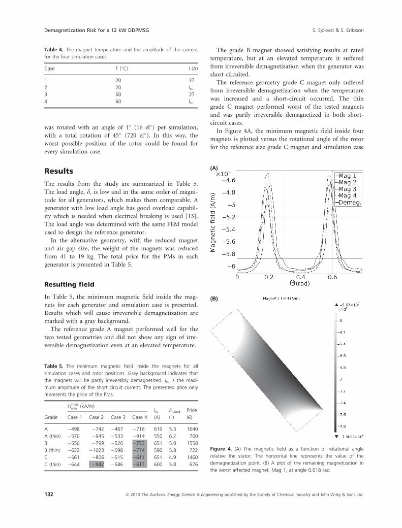
In Figure 4A, the minimum magnetic field inside four
magnets is plotted versus the rotational angle of the rotor
for the reference size grade C magnet and simulation case
Table 4. The magnet temperature and the amplitude of the current
for the four simulation cases.
Case T (�C) I (A)
1 20 37
2 20 Isc3 60 37
4 60 Isc
Table 5. The minimum magnetic field inside the magnets for all
simulation cases and rotor positions. Gray background indicates that
the magnets will be partly irreversibly demagnetized. Isc is the maxi-
mum amplitude of the short circuit current. The presented price only
represents the price of the PMs.
Grade
Hmagmin (kA/m)
Isc drated Price
Case 1 Case 2 Case 3 Case 4 (A) (�) (€)
A �498 �742 �467 �716 619 5.3 1640
A (thin) �570 �945 �533 �914 550 6.2 760
B �550 �799 �520 �753 651 5.0 1558
B (thin) �632 �1023 �598 �774 590 5.8 722
C �561 �806 �515 �611 651 4.9 1460
C (thin) �644 �942 �586 �617 600 5.8 676
(A)
(B)
Figure 4. (A) The magnetic field as a function of rotational angle
relative the stator. The horizontal line represents the value of the
demagnetization point. (B) A plot of the remaining magnetization in
the worst affected magnet, Mag 1, at angle 0.018 rad.
132 ª 2013 The Authors. Energy Science & Engineering published by the Society of Chemical Industry and John Wiley & Sons Ltd.
Demagnetization Risk for a 12 kW DDPMSG S. Sj€okvist & S. Eriksson

4. In Figure 4B, the result of demagnetization for the
worst affected magnet, at the worst angle 0.018 rad, is
depicted. The gray shaded area in Figure 4B represents
the area that will suffer from irreversible demagnetization.
The white areas of the magnet represent values over 97%,
which represent the linear part of the BH curve before
the knee point, that is, will not be irreversibly demagne-
tized. The dark area will be the most damaged. In this
case the demagnetization point was �587 kA/m, repre-
sented by the horizontal line in Figure 4A.
Discussion
In the case with the smaller alternative geometry, the
diameter of the rotor is a bit larger than in the reference
geometry to compensate for the smaller air gap and thin-
ner magnets. The extra space given on the periphery of
the rotor could be used for wider magnets. In this case
the change was small +1.2 mm/magnet and the same
magnet width was used for both geometries. If the change
had been larger, the PM width should be compensated to
keep the same power [14].
For the smaller generator geometry the total weight of
the magnets is less than half than for the standard geome-
try. This also reduces the price of the magnets aliquot.
Since the price of NdFeB magnets has increased substan-
tially the last few years, the use of smaller magnets and
air gap is one way to reduce the cost for PM generators.
The results from this study show that the best alterna-
tive, if one were to build a similar generator, is to choose
the smaller geometry with the grade A magnets. The cost
for the PMs is then reduced by � 54%, compared to the
reference generator. The price difference to the small
grade B magnet is small and thereby hard to motivate
with the better performing grade A magnet.
On the other hand, when a smaller air gap is used,
more consideration is needed to the choice of PMs. Fur-
ther, when the air gap width is decreased, higher demands
are placed on tolerances of the construction, increasing
the cost. Even small errors in tolerance can propagate
throughout the construction and cause severe problems
in other parts of the structure. This might increase the
cost for the supporting structure of the generator.
Even though the event of a short circuit is very critical
for a generator it is sometimes not worth protecting the
magnets against these events if the event is very unlikely
or leads to complete destruction. This could motivate the
use of one of the cheaper magnet grades.
The goal with the design of the alternative generator
was to get similar electrical properties as the reference
generator. A negative aspect of this design is that the load
angle increases when smaller magnets are used, this could
be compensated by adding 15–20% more PM material.
The alternative design would still be much cheaper and
the induced voltage would also increase a bit due to lar-
ger magnets.
Conclusions
A new proprietary FEM model has been presented and
shows in this study that there is no risk of demagnetizing
the magnets in the built 12 kW PM generator, under the
assumed conditions. However, the cheaper magnets in the
study suffered from partial irreversible demagnetization in
most of the short-circuit cases.
In conclusion, designing a generator to avoid demagne-
tization is a cost optimization process considering magnet
material, cooling equipment, and construction tolerances.
Acknowledgment
This work has been carried out with funding from the
Swedish Research Council, grant number 2010-3950.
Conflict of Interest
None declared.
References
1. Sebastian, T., and G. Slemon. 1987. Transient torque and
short circuit capabilities of variable speed permanent
magnet motors. IEEE Trans. Magn. 23:3619–3621.
2. Ruoho, S., J. Kolehmainen, J. Ikheimo, and A. Arkkio.
2010. Interdependence of demagnetization, loading, and
temperature rise in a permanent-magnet synchronous
motor. IEEE Trans. Magn. 46:949–953.
3. Goldemberg, C., L. Lebensztajn, and O. S. Lobosco. 1997.
Analysis of short-circuit transients of a PM machine.
WB2/13.1–WB2/13.3in 1997 IEEE International
Electric Machines and Drives Conference Record,
February, Milwaukee, WI, 18–21 May 1997.
4. Thelin, P. 2002. Short circuit fault conditions of a buried
PMSM investigated with FEM. Proceedings of the Nordic
Workshop on Power and Industrial Electronics, NORpie
2002, August, Stockholm, Sweden.
5. Eriksson, S. 2008. Direct driven generators for vertical axis
wind turbines. Ph.D. diss. Comprehensive summaries of
Uppsala dissertations from the Faculty of Science and
Technology 547. Acta Universitatis Upsaliensis, Uppsala,
Sweden, ISBN: 978-91-554-7264-1.
6. Eriksson, S., A. Solum, M. Leijon, and H. Bernhoff. 2008.
Simulations and experiments on a 12 kW direct driven PM
synchronous generator for wind power. Renew. Energy
33:674–681.
7. Eriksson, S., H. Bernhoff, and M. Leijon. 2009. FEM
simulations and experiments of different loading conditions
ª 2013 The Authors. Energy Science & Engineering published by the Society of Chemical Industry and John Wiley & Sons Ltd. 133
S. Sj€okvist & S. Eriksson Demagnetization Risk for a 12 kW DDPMSG

for a 12 kW direct driven PM synchronous generator for
wind power. Int. J. Emerg. Electr. Power Syst. 10: Article 3.
8. Deglaire, P., S. Eriksson, J. Kjellin, and H. Bernhoff. 2007.
Experimental results from a 12 kW vertical axis wind
turbine with a direct driven PM synchronous generator. in
Proceedings of EWEC 2007 - European Wind Energy
Conference & Exhibition, Milan, Italy, 7–10 May.
9. Vacuumschmelze GmbH. 2012 http://www.vacumschmelze.com/
(accessed 17 August 2012).
10. Ruoho, S., and A. Arkkio. 2008. Partial demagnetization of
permanent magnets in electrical machines caused by an
inclined field. IEEE Trans. Magn. 44:1773–1778.
11. Katter, M. 2005. Angular dependence of the
demagnetization stability of sintered Nd-Fe-B magnets.
IEEE Trans. Magn. 41:3853–3855.
12. Ruoho, S., E. Dlala, and A. Arkkio. 2007. Comparison of
demagnetization models for finite- element analysis of
permanent-magnet synchronous machines. Magnetics
43:3964–3968.
13. Eriksson, S., and H. Bernhoff. 2011. A 225 kW direct
driven PM generator adapted to a vertical axis wind
turbine. Adv. Power Electron. 2011.
14. Wang, F., J. Pan, Y. Zhang, X. Cai, and J. Du. 2011.
Design and performance of large scale direct-driven
permanent magnet wind generators. 1–5in Proceedings of
the 2011 International Conference on Power Engineering,
Energy and Electrical Drives, February.
134 ª 2013 The Authors. Energy Science & Engineering published by the Society of Chemical Industry and John Wiley & Sons Ltd.
Demagnetization Risk for a 12 kW DDPMSG S. Sj€okvist & S. Eriksson