Study of Centrifugal Sugar by Electrical Machines
64
Sudan university of Science and Technology College of Engineering School of Electrical and Nuclear Engineering Study of Centrifugal Sugar by Electrical Machines يضب ل ضف ن ةس ر ديبهل ت يك ل ةطس و ب A project Submitted In partial Fulfillment for the Requirement of the Degree of B.Sc. (Honor) In Electrical Engineering Prepared By: 1. Ahmed Mohammad Ahmed Mohammad 2. Alamin Mohammad Alamin Mohammad 3. Alnair Eltaib Ahmed Mohammad 4. Mansour Hamid Mohammad Hamad Supervised by U.S. Maha Osman October 2015
Transcript of Study of Centrifugal Sugar by Electrical Machines
8/19/2019 Study of Centrifugal Sugar by Electrical Machines
http://slidepdf.com/reader/full/study-of-centrifugal-sugar-by-electrical-machines 1/64
Sudan university of Science and Technology
College of Engineering
School of Electrical and Nuclear Engineering
Study of Centrifugal Sugar by Electrical
Machines
نفض ل بيض
بو سطة ل كي ت لهبيدر سة
A project Submitted In partial Fulfillment for the Requirement of the
Degree of B.Sc. (Honor) In Electrical Engineering
Prepared By:
1.
Ahmed Mohammad Ahmed Mohammad
2. Alamin Mohammad Alamin Mohammad
3.
Alnair Eltaib Ahmed Mohammad
4.
Mansour Hamid Mohammad Hamad
Supervised byU.S. Maha Osman
October 2015

8/19/2019 Study of Centrifugal Sugar by Electrical Machines
http://slidepdf.com/reader/full/study-of-centrifugal-sugar-by-electrical-machines 2/64
I
ـ ـ ـ ـ ـ ـ ـ ـ ـ ـ ـ ـ ـا
طفك ك إ أن د ابأ آك
ع ذي عده ا ل ـ ﴿
ا
رآه ف
أ أم شأأ
ر ضف اذ
ل عده
ف ش و
غ
ر ن ف و٤ يد أ ظ شع وا ذل ا ن أم
دون كشع اذأ جءت ف
ا وأو
﴾ و
ظا قدص
ا٤ ا ةرس

8/19/2019 Study of Centrifugal Sugar by Electrical Machines
http://slidepdf.com/reader/full/study-of-centrifugal-sugar-by-electrical-machines 3/64
II
DEDICATION
To our parents who always inspiring and devising us, nothing of this could
be done without them, may Allah saves them always for us. To our dears, all family
members who always be there when we need them .To our best friends and
colleagues who are always with us step by step, supports us to go forward to
everyone who is an integral part of our support group, We dedicate this work.

8/19/2019 Study of Centrifugal Sugar by Electrical Machines
http://slidepdf.com/reader/full/study-of-centrifugal-sugar-by-electrical-machines 4/64
III
ACKNOWLEDGEMENT
The greatest thanks to Allah always before and after .We would like to
express our deep gratitude to everyone who helps us throughout this work at any
step of it .Most grateful and appreciation to our supervisor: UST: MAHA OSMAN
For their expertise support and endless valuable advices which guided us
throughout this work and our engineering career life .We also would like to thanks
chief engineer in Assalaya sugar factory El gaily Dafaseed Fadl El mola, and
lewaa eldin who an engineer in kenana sugar factory. Thanks all our teachers in the
school of electrical and nuclear engineering for all the help and knowledge that
and finally thankful be to everyone helped and contributed us fromthey gave to us .
.Sc. degree.We hope improvinrewardthe beginning until to the completion of the B
and success for all.

8/19/2019 Study of Centrifugal Sugar by Electrical Machines
http://slidepdf.com/reader/full/study-of-centrifugal-sugar-by-electrical-machines 5/64
IV
Abstract
This study concern about separation of white sugar through centrifugal
machines and that in kenana sugar factory where they use DC motor while in
assalaya they use induction motor.
Three stages of the operation mechanism were studied , the first stages is
feeding the mixture (sugar + molasses) ,it takes 40 seconds then spin level and it
duration about 80 seconds which called production level and separate sugar from
molasses and at last the plough discharge sugar for 60 seconds.
Programmed logic control was used to simulate one machine operation ,and
at last comparison between two systems use in kenana sugar factory and assalaya
was made.

8/19/2019 Study of Centrifugal Sugar by Electrical Machines
http://slidepdf.com/reader/full/study-of-centrifugal-sugar-by-electrical-machines 6/64
V
مخحل
ذو يزا طق ت اد ابض ن ا ض ن سارا ه
ح ك مخ ح س عو ر كب ل يا س عب
ل .
خب ااد ح وا حا ح ظا ل احل ث سرد
(س+)ة ذو4ا ح ا حب ف (4)ح و
(4.)ب ح ا,(ل ا ن ا)اج
ر أو لشا أ ةحاو كس ة ا ا تا ماخسا
س ع دا مظاو س ع مخا مظا نب

8/19/2019 Study of Centrifugal Sugar by Electrical Machines
http://slidepdf.com/reader/full/study-of-centrifugal-sugar-by-electrical-machines 7/64
VI
LIST OF CONTENTSSubject Page
ا I
Dedication II
Acknowledgement III
Abstract IVArabic Abstract V
List of Contents VI
List of Figures VIII
List of Tables IX
List of symbols X
List of Abbreviations
XI
CHAPTERONE
INTRODUCTION 1
Background 1
Problem Statement 1
Objectives 2
Methodology 2
Lay out of project 2
CHAPTER TWO
BATCH CENTRIFUGAL 3
Cane Sugar Production 3
Batch Centrifugal Description 7
Cycle Operation 19
CHAPTER THREE
CENTRIFUGAL CYCLE
21
Batch centrifugal drives 21
Sequence Of Centrifugal Machines 24
CHAPTER FOUR
SIMULATIO AND COMPRESSION 31
Programmable logic controller 31

8/19/2019 Study of Centrifugal Sugar by Electrical Machines
http://slidepdf.com/reader/full/study-of-centrifugal-sugar-by-electrical-machines 8/64
VII
4.2 Centrifugal Process 32
4.3 Simulation 34
4.4 Result of simulation 36
4.5
Comparisons between DC Motor And Induction Motor In
centrifugal system 37
CHAPTER FIVE
CONCLUSION AND
RECOMMENDATIONS
38
5.1 Conclusion 38
5.2 Recommendations 38
REFERENCES39
APPENDIXESAppendix A 40-43
Appendix B 44
Appendix C 45-52

8/19/2019 Study of Centrifugal Sugar by Electrical Machines
http://slidepdf.com/reader/full/study-of-centrifugal-sugar-by-electrical-machines 9/64
VIII
LIST OF FIGURES
Figure NO Description Page
2.1 Simplified process flow diagram for cane sugar production
7
2.2 General Arrangement of Centrifuge 11 3.1 Speed and motor current against time for an inverter
drive
8
3.2 centrifuge cycle time 04
3.3 5/10 Broadbent sequence connection with PLC 01
3.4 Main Screen 00
3.5 Spin Screen 0
3.6 Sequence Selecting Icons 0
4.1 Simplified process flow diagram for centrifugal 0
4.2 Simulation program 4

8/19/2019 Study of Centrifugal Sugar by Electrical Machines
http://slidepdf.com/reader/full/study-of-centrifugal-sugar-by-electrical-machines 10/64
IX
LIST OF TABLES
Table NO Description
Page
4.1 result of simulation 1
4.2
Comparisons between DC Motor And Induction
Motor In centrifugal system
8

8/19/2019 Study of Centrifugal Sugar by Electrical Machines
http://slidepdf.com/reader/full/study-of-centrifugal-sugar-by-electrical-machines 11/64
X
LIST OF SYMBOLS
Symbols Meaning
Cº Celsius degree
Fº Fahrenheit degree
A Ampere NS Spinning speed
NF Feeding speed
NP Ploughing speed
TF Feeding time
TFT Time of feeding timer
TS Spinning time
TST Time of spinning timer
TP Ploughing time
TPT Time of ploughing timerTW Washing time
TR Repair time
TRT Time of repair timer
TSS Steam time
T(T003) Time of begin washing timer
T(T004) Time of begin steam timer

8/19/2019 Study of Centrifugal Sugar by Electrical Machines
http://slidepdf.com/reader/full/study-of-centrifugal-sugar-by-electrical-machines 12/64
XI
LIST OF ABBREVIATIONS
Abbreviation Meaning
DC Direct current
AC Alternative current
PLC programmable logic controllerEMC Electromagnetic compatibility
CPU Central processor unit
PSU Power supply unit
LED Light Emitting Diode
Rpm Revolution per minute
PWM Pulse width modulated
IGBT Integrated gate bipolar transistor
KW Kilo wattLAD Ladder diagram
FBD Function block diagram
HMI Human machines interface
8/19/2019 Study of Centrifugal Sugar by Electrical Machines
http://slidepdf.com/reader/full/study-of-centrifugal-sugar-by-electrical-machines 13/64
1
CHAPTER ONE
INTRODUCTION
1.1 Background
Sugarcane processing is a production of sugar from sugarcane, there are by
products of the processing including bagasse, molasses, and filter cake. Bagasse is
the residual woody fiber of the cane, is used as fuel source for the boilers in the
generation of process steam, Bagasse also is used as production of numerous papers
and Paper board products and reconstituted panel board. Thus, bagasse is arenewable resource. Dried filter cake is used as an animal feed supplement,
fertilizer, and source of sugarcane wax. The final byproduct is Molasses is used as
edible syrup. And also used to produce ethanol, compressed yeast, citric acid, and
rum. The primary goal of harvesting is to deliver to the processing mill good
quality sugarcane stalks with a minimum of trash. During harvesting, the cane tops
and leaves are removed because they contain little sucrose but are high in starch
and reducing sugars, which reduces sugar yields [1].
1.2 Problem Statement
Study the duty cycle operation of the batch sugar centrifugal machine in sugar
factories.
1.3 Objectives
The objective of this study is to know the effect of batch sugar centrifugal
machines which work in production of sugar and comparison between AC
centrifugal and DC.

8/19/2019 Study of Centrifugal Sugar by Electrical Machines
http://slidepdf.com/reader/full/study-of-centrifugal-sugar-by-electrical-machines 14/64
2
1.4 Methodology
At the beginning of the research we started to collect data by paying field
visit to kenana sugar factory and another assalaysa sugar factory, so as to see the
operation of the centrifugal and the relevant equipment. In addition to data we
abstracted from our observation, we also received detailed information about the
operation process from the engineering teams in the factories.
Then a simulated design of operation system based on the data collected
using PLC, after running the PLC simulation program the results vary with time
that’s put in the table.
1.5 Layout of the Project
This project consists of an abstract and five chapters. Chapter one is
introduction which consists sugar industry description, problem, objectives,
methodology and the last one is layout of the project. Chapter two is sugar
production, batch centrifugal description ,Cycle Operation, chapter three is Batch
centrifugal drives, Sequence of Centrifugal Machines, chapter four is
Programmable logic controller, Centrifugal Process, Simulation, Result of
simulation, Comparisons between DC Motor And Induction Motor In centrifugal
system, chapter five is conclusion, recommendations.

8/19/2019 Study of Centrifugal Sugar by Electrical Machines
http://slidepdf.com/reader/full/study-of-centrifugal-sugar-by-electrical-machines 15/64
3
CHAPTER TWO
BATCH CENTRIFUGAL
2.1Cane Sugar Production
A simplified process flow diagram for a typical cane sugar production plant
is shown in Figure 2-1. The cane is received at the mill and prepared for extraction
of the juice. At the mill, the cane is mechanically unloaded and placed in a large
pile. Prior to milling, the cane is cleaned, usually with high pressure water, the
milling process occurs in two steps: first is breaking the hard structure of the cane
and second is grinding the cane. Breaking the cane uses revolving knives,
shredders, crushers, or a combination of these processes. For the grinding, or
milling, of the crushed cane, a three-roller mill is most commonly used although
some mills consist of four, five, or six rollers in a single mill. Multiple sets of mills
are used with combinations of 15 to 18 rollers being predominant. Conveyors
transport the crushed cane from one mill to the next. Imbibitions are the process in
which water or juice is applied to the crushed cane to enhance the extraction of the
juice at the next mill. The common procedure is to send the juice from the crusher
and the first two mills for further processing. In imbibitions, water or juice from
other processing areas is introduced into the last mill and transferred from mill to
mill towards the first two mills while the crushed cane travels from the first to the
last mill. The crushed cane exiting the last mill is called bagasse. The juice from the
mills is strained to remove large particles and then clarified.
Clarification is done almost exclusively with heat, and lime and phosphoric
acid is added. The lime is added to neutralize the organic acids and the temperature
of the juice is raised to about 95oC (200 oF). A heavy precipitate forms which is
separated from the juice in the clarifier. The phosphate acts as a flocculating agent.
8/19/2019 Study of Centrifugal Sugar by Electrical Machines
http://slidepdf.com/reader/full/study-of-centrifugal-sugar-by-electrical-machines 16/64
4
The insoluble particulate mass, called "mud", is separated from the limed juice by
gravity. Clarified juice goes to the evaporators without additional treatment. The
mud is filtered and the filter cake is washed with water; the wash water is added to
the juice recovered during filtration. The juice is screened again before going to
evaporate water.
Evaporator stations consist of a series of evaporators, termed multiple-effect
evaporators. This process typically uses a series of five evaporators.
Steam from large boilers is used to heat the first evaporator, and the steam
from the water evaporated in the first evaporator is used to heat the second
evaporator. This heat transfer process continues through the five evaporators and asthe temperature decreases (due to heat loss) from evaporator to evaporator, the
pressure inside each evaporator also decreases which allows the juice to boil at the
lower temperatures in the subsequent evaporator. Some steam is released from the
first three evaporators, and this steam is used in various process heaters in the plant.
The evaporator station in raw sugar manufacture typically produces syrup with
about 65 percent solids and 35 percent water. Following evaporation, the syrup is
clarified by adding lime, phosphoric acid, and a polymer flocculent, aerated, and
filtered in the clarifier.

8/19/2019 Study of Centrifugal Sugar by Electrical Machines
http://slidepdf.com/reader/full/study-of-centrifugal-sugar-by-electrical-machines 17/64
5
Figure(2.1):Simplified process flow diagram for cane sugar Production[1].

8/19/2019 Study of Centrifugal Sugar by Electrical Machines
http://slidepdf.com/reader/full/study-of-centrifugal-sugar-by-electrical-machines 18/64
6
From the clarifier, the syrup goes to the vacuum pans for
crystallization. Crystallization of the sugar starts in the vacuum pans, whose
function is to produce sugar crystals from the syrup. Batch pan boiling
systems is used in the pan boiling process. The syrup is evaporated until it
reaches the super-saturation stage. At this point, the crystallization process is
initiated by "seeding" solution. When the volume of the mixture of liquor and
crystals, known as mesquite, reaches the capacity of the pan, the evaporation
is allowed to proceed until the final mesquite is formed. At this point, the
contents of the vacuum pans (called "strike") are discharged to the
crystallizer. The function of the crystallizer is to maximize the sugar crystal
removal from the mesquite. From the crystallizer, the mesquite (A mesquite)
is transferred to high-speed centrifugal machines (centrifugal), in which the
mother liquor (termed "molasses") is centrifuged to the outer shell and the
crystals remain in the inner centrifugal basket. The crystals are washed with
water and the wash water centrifuged from the crystals. The liquor (A
molasses) from the first centrifugal is returned to a vacuum pan and re-boiled
to yield a second mesquite (B mesquite), that in turn yields a second batch of
crystals. The B mesquite is transferred to the crystallizer and then to the
centrifugal, and the cane sugar is separated from the molasses. This cane
sugar is combined with the first crop of crystals. The molasses from the
second boiling (B molasses) is of much lower purity than the first molasses. It
is re-boiled to form a low grade mesquite (C mesquite) which goes to a
crystallizer and then to a centrifugal. This low-grade cane sugar is mingled
with syrup and used in the vacuum pans as a "seeding" solution. The final
molasses from the third stage is a heavy, viscous material used primarily as a
supplement in cattle feed. The cane sugar from the combined A and B
mesquites is dried in fluidized bed or spouted bed driers and cooled. After
cooling, the cane sugar is transferred to packing bins and then sent to bulk
storage [1].
8/19/2019 Study of Centrifugal Sugar by Electrical Machines
http://slidepdf.com/reader/full/study-of-centrifugal-sugar-by-electrical-machines 19/64
7
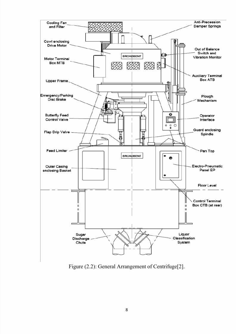
2.2 -Batch Centrifugal Description
Batch Centrifuges are filtration machines used to separate sugar
mesquite into its constituent crystals and mother liquor under the action of
centrifugal force. The product is processed in a cylindrical perforated basket
fitted with filtering screens which is hung on the bottom end of a long spindle.
The spindle is suspended from a resilient buffer which allows the
rotating assembly to swing slightly to find its own balanced axis of rotation
thus reducing transmission of vibration to the support platform. The
centrifuge is driven by an electric induction motor running off a variable
frequency supply from a solid state inverter which allows a continuously
running speed. show appendix A
All mechanisms used for feeding and discharging product are
pneumatically actuated and the whole machine cycle is controlled by a
programmable logic controller (PLC ) [2].
8/19/2019 Study of Centrifugal Sugar by Electrical Machines
http://slidepdf.com/reader/full/study-of-centrifugal-sugar-by-electrical-machines 20/64
8
Figure (2.2): General Arrangement of Centrifuge[2].

8/19/2019 Study of Centrifugal Sugar by Electrical Machines
http://slidepdf.com/reader/full/study-of-centrifugal-sugar-by-electrical-machines 21/64
9
* Principles of Operation
The centrifuge processes batches of product in a cyclic manner as
follows; the centrifuge accelerates to a low speed. The butterfly feed control
valve and a flap valve open allowing product to flow down a feeding chute
onto a flinger disc attached to the spindle. This throws the product onto the
inside of the basket where it flows under centrifugal force to form a uniform
wall. Liquor starts to flow out through the filtering screens and basket
perforations and is collected in the outer casing and discharged down pipe-
work under the machine. The product thickness builds up inside the basket
until the feed detector trips causing the feed control valve to close. The inside
of the feed chute is sprayed with water and after a short delay the flap valve
closes to prevent any remaining dark colored product dripping onto the
product inside the basket. The feeding rate depends on how far the feed valve
opens and this can be manually or automatically controlled. On completion of
feeding, the centrifuge accelerates to a medium speed hold point to await
operator or sequence permission to proceed. The centrifuge then acceleratesto its maximum spin speed. During this time, purging of liquor from the
product cake continues and water and steam can be sprayed on to remove the
final traces of mother-liquor from the crystals. The purity of the run off liquor
rises and a classification valve system can be used to direct this liquor down a
different discharge pipe. The centrifuge pauses at spin speed for a preset time
to dry the crystal cake to the desired level. On completion of spinning, the
centrifuge decelerates to a very low speed. A discharge valve plate under the
bottom of the basket opens. A plough blade cuts into the top of the cake and
moves slowly down the basket screens discharging dried crystals through the
basket bottom and down a chute onto a conveyor running beneath the casing.
The plough blade moves back to its parked position, the discharge valve
shuts, and the machine accelerates to feed speed to begin another cycle.

8/19/2019 Study of Centrifugal Sugar by Electrical Machines
http://slidepdf.com/reader/full/study-of-centrifugal-sugar-by-electrical-machines 22/64
10
During acceleration, the filtering screens can sprayed with a small amount of
water to remove any remaining crystals and thus prevent clogging [2].
* Basket
The basket is a high integrity fabrication made from materials
appropriate to the product being processed. The shell is rolled from plate,
seam welded, and perforated. Depending on the operating speed and density
of the product, the shell may be reinforced by shrink fitted, high tensile,
seamless rolled hoops. The basket bottom includes a hub for attachment to the
spindle and a spoked opening for product discharge. The basket top is an
annular disc that’s inside diameter or 'lip' determines the maximum possible
product cake thickness which can be accommodated. The perforated shell of
the basket is lined with 3 screens. The innermost 'working' screen is made
from thin metal plate which has many fine perforations and acts as the filter
medium. The 'intermediate' screen is fine woven mesh, and the 'backing'
screen is coarse woven mesh. The system is designed to optimize support of
the working screen whilst allowing easy dispersion of the liquor filtrate [2].
* Main Drive Induction Motor
The cyclic duty induction motor is an induction motor specially
designed for high torque variable speed duty. It operates from a variable
frequency supply and has much lower headroom requirements than an
equivalent conventional motor .The stator is a 3 phase winding in a laminatedcore with skewed slots to minimize harmonics. The stator frame is of
fabricated construction and bolts directly to the spindle bearing housing. The
rotor has a low resistance cage in a laminated core and is fitted on a fabricated
spoked hub which is attached directly to the spindle. The motor is enclosed by
a cowl which provides EMC and noise shielding and includes mesh covered
air ducts to allow cooling air to escape. The motor cowl also includes themain motor terminal box. The motor is force ventilated from above by a
8/19/2019 Study of Centrifugal Sugar by Electrical Machines
http://slidepdf.com/reader/full/study-of-centrifugal-sugar-by-electrical-machines 23/64
11
separate electric motor driven centrifugal fan unit. The air delivered by the
cooling fan is drawn through an oil wetted filter to prevent any dust or debris
being fed into the internal motor assembly. A rotating baffle on the top of the
rotor splits this cooling air flow so that some passes directly across the upper
end-windings whilst the remainder passes down the inside of the rotor and a
cross the lower end-windings [2].
* Main Drive Direct current Motor
D.C motor separate specially designed for high torque variable speed
duty. It is operate from a variable voltage supply .This motor cool by another
induction motor to prevent any dusty [2].show name plate at appendix A
* Spindle and Bearing Housing
The spindle is a long tubular shaft with the basket attached at the
bottom and the motor at the top. The spindle is suspended in a bearing
housing just below the motor. The spindle is located radially by two
cylindrical roller bearings and vertically by a 4 point angular contact ball
thrust bearing which are all retained in a cast bearing housing. All bearings
are grease lubricated and rated for long life. Just beneath the bearing housing
is a disc brake for parking and emergency duties (In normal operation, the
centrifuge is decelerated by regeneration in the inverter). The disc is attached
to the spindle by a split taper collar. The caliper is mounted on a bracket
attached to the lower bearing cap. The disc and brake shoes are surrounded by
a substantial guard. Lower down the spindle is a conical flinger disc to aid
distribution of product in the basket. This is also attached to the spindle by a
split taper hub [2].

8/19/2019 Study of Centrifugal Sugar by Electrical Machines
http://slidepdf.com/reader/full/study-of-centrifugal-sugar-by-electrical-machines 24/64
12
* Casing and Support Frame
The spindle bearing housing is flexibly supported in a conical
elastomer bush or 'buffer' which allows the whole rotating assembly to swing
slightly. The buffer rests in a conical seating in the top of a rigid support
frame which has splayed legs fabricated from square hollow tube. The frame
is in turn supported from the casing with intermediate packing plates whose
thickness can be changed to adjust the vertical position of the basket. The
casing is a fabricated assembly comprising a central cylinder with boxed
sides. The cylindrical section surrounds the basket to catch the spun off liquor
and incorporates a bottom gutter and bump ring to restrict the lateral motion
of the basket. The side frames transfer loads from the upper support frame
direct to the supporting foundations [2].
* Cooling and anti-precession system
The motor cowl supports an auxiliary motor driven fan and filter unit
which directs cooling air via a duct into the top of the main drive motor.
An anti-precession system is fitted to control gyration of the rotating
assembly during feeding and to prevent gyroscopic precession at high speed.
This comprises a damper plate with a friction lining which is pressed down
onto the motor top by 3 springs mounted on the motor cowl. The damper plate
is held centrally by a rubber ring which is a tight fit on the cooling air duct.
When the rotating assembly swings, the motor top is forced to slide against
the damper plate giving rise to frictional damping [2].
* Braking System
In normal operation, the centrifuge is decelerated only by regeneration
by the Drive Panel and mechanical brake [1].
8/19/2019 Study of Centrifugal Sugar by Electrical Machines
http://slidepdf.com/reader/full/study-of-centrifugal-sugar-by-electrical-machines 25/64
13
* Feeding System
Product is fed into the centrifuge via a flow control valve, streamlined
feed spout and secondary anti-drip valve. The product falls onto a conical
distributor disc or 'flinger' attached to the spindle by a split taper hub. This
throws the product onto the basket inner wall approximately halfway up from,
where it flows to form a product wall under centrifugal action.
The flow control valve is a butterfly valve with a double acting actuator
controlled from an integral electro-pneumatic positioner which responds to a
4-20 mA signal from the PLC. The flow control valve is mounted as close as
possible to the mixer tank to avoid plugging. To avoid unsightly drips of
colored feedstock onto spun product, a secondary valve is mounted directly
onto the casing top. The secondary valve is a flap pulled up onto a soft seating
under the spout outlet by a pair of double acting pneumatic cylinders.
Mounted locally is an air reservoir with sufficient capacity to allow
emergency closing of both valves in the event that the main pneumatic supply
fails [1].
* Feed Limiter
A mechanical feed limiter unit initiates closing of the feed valve when
the build-up of product cake inside the basket reaches the desired thickness.
This comprises a slipper arm inside the basket connected via a rod to a control
box on the casing top. The control box contains a pneumatic cylinder and
spring loaded linkages. Just before feeding, the cylinder pushes the slipper
close to the basket wall. As the product cake thickens, the slipper rides on the
cake surface under spring pressure until the lever arms in the control box
move sufficiently to trip a proximity switch. This sends a signal to close the
feed valve and releases the cylinder in the control box so that the slipper arm
moves well away from the product for the remainder of the cycle. The rodfrom the slipper arm extends through to a handle on the top of the control box

8/19/2019 Study of Centrifugal Sugar by Electrical Machines
http://slidepdf.com/reader/full/study-of-centrifugal-sugar-by-electrical-machines 26/64
14
which can be used as a manual override to terminate feeding. The desired
product cake thickness is adjusted by rotating the whole assembly on the
casing top [2].
* Plough Discharger
Product is ploughed from the basket by a blade which remains within
the basket at all times. Its parked position is near the spindle near the top of
the basket. For discharging, the blade lifts slightly, moves horizontally to cut
into the top of the cake, pauses, and moves slowly vertically down the basket
screens, pauses, moves vertically up, moves horizontally back to the spindle
and finally drops slightly into the parked position. All plough motions take
place with the basket rotating at very slow speeds. The actuating mechanism
is mounted to the right of the main support frame and is connected to the
blade by an 'L' shaped arm which passes through a curved slot with a sliding
cover in the casing top. The heart of the mechanism is a vertical circular shaft
on which the carriage supporting the plough arm slides vertically under the
action of double acting pneumatic cylinder mounted in parallel with an oil
filled dashpot unit. The dashpot allows a slow, adjustable speed downwards
during plough. And a fast upwards motion when returning to the parked
position. The horizontal motion is obtained by a second double acting
pneumatic cylinder pushing on a lever arm attached to the bottom of the
plough shaft which rotates the shaft and carriage in bushes at the casing top
and at the top of the upper frame. Rollers in the end of the lever arm move the
plough arm. The geometry in plain view is such that under cutting action, the
blade naturally 'castors' to about half the maximum cake thickness. When first
pushing the blade into the cake, the horizontal cylinder operates at full
pressure but once on the screens, the pressure is reduced to gently hold the
blade lightly against the basket to ensure that all traces of product are

8/19/2019 Study of Centrifugal Sugar by Electrical Machines
http://slidepdf.com/reader/full/study-of-centrifugal-sugar-by-electrical-machines 27/64

8/19/2019 Study of Centrifugal Sugar by Electrical Machines
http://slidepdf.com/reader/full/study-of-centrifugal-sugar-by-electrical-machines 28/64
16
* Process Fitments
A static hot water spray pipe protruding into the basket from the casing
top allows the screens to be rinsed after ploughing and the product to be
washed during spinning. The pipe is short to prevent 'dragging' in the product
during ploughing. The spray nozzles sizes, positions and angles have been
carefully selected to provide an even wash distribution. The wash is
controlled by a pneumatically actuated ball valve attached to the end of the
wash pipe. An optional short steam injection pipe protruding into the basket
from the casing top allows steam to be added to help dry the product cake.
The steam injection is controlled by a pneumatically actuated ball valve
attached to the end of the steam pipe. An optional liquor classification unit is
attached to the rectangular liquor outlet under the casing. This allows
separation of the initial low purity mother liquor spun off immediately after
feeding from the wash water containing dissolved product spun off later. It
comprises a ‘Y’ splitter box with a pair of pneumatically actuated butterfly
valves on the two outlets. The controls are organized such that both valves arenever shut simultaneously [2].
* Control Panel (PLC)
The whole production cycle of the machine, including operation of the
inverter, feed valves, plough, and the discharge valve and process fitments is
controlled by an electronic Programmable Logic Controller (PLC). The PLC
together with its interface devices and auxiliaries is housed in a remote
Control Panel cabinet. An isolator, 'Power On' indicator and 'Machine
Running' indicator are mounted on the outside of the door. Components inside
include the following:

8/19/2019 Study of Centrifugal Sugar by Electrical Machines
http://slidepdf.com/reader/full/study-of-centrifugal-sugar-by-electrical-machines 29/64
17
** Central Processor Unit (CPU)
The CPU is a solid state device consisting of a microprocessor and its
support system. It contains the operating program for the machine within its
EPROM memory. The program cannot normally be corrupted but changes
can be made when required by a suitably qualified and experienced person
using a special programming unit. The CPU scans the inputs to the PLC
from the various sensors on the centrifuge, acts upon these inputs as
determined by the program, and then turns on the appropriate outputs to the
inverter and centrifuge actuators in a cyclic manner. A series of indicating
LEDs are incorporated on the front of the unit to show the operating status ofthe unit.
** Power Supply Unit (PSU)
This separate unit supplies 24V D.C. to the input/output module
mounted on the rack. A light on the PSU indicates when the power supply is
active.
** Input Modules
The input modules are all 16 way, low voltage DC. Optically isolated
positive logic units. Each input has an associated Light Emitting Diode (LED)
on the front of the unit to indicate its status (ON or OFF).
** Output Modules
The output modules are all 16 ways, low voltage DC optically isolated
positive logic units. Each output has an associated LED on the front of the
unit to indicate its status (ON or OFF) [2].
* Speed Monitoring System
The speed of the machine is measured by impulses from two proximitysensors mounted above a series of holes through the brake disc. To guard
8/19/2019 Study of Centrifugal Sugar by Electrical Machines
http://slidepdf.com/reader/full/study-of-centrifugal-sugar-by-electrical-machines 30/64
18
against faulty speed control, two entirely independent speed monitoring
systems are fitted. In the main system, the impulses from one of the sensors
are changed to a 4-20 mA analogue signal by a frequency to current converter
and this analogue signal is fed to the main PLC. In the secondary system, the
impulses from the second sensor are fed directly to a secondary
programmable logic controller (PLC2) which is of a different type and
manufacture to the main PLC. PLC2 is basically a pulse counting unit and is
configured to operate 6 sets of contacts corresponding to different speeds. The
main PLC continuously scans the status of these contacts and compares these
for consistency with its own measurement of speed. If a discrepancy is
detected, a fault condition occurs. As a further protection against faults in the
main PLC and/or the inverter causing random uncontrolled actions, some of
the contacts in PLC2 are hard wired via relays to inhibit dangerous
conditions. One set of contacts isolates the plough actuators to prevent the
plough deploying above low speed. Another set of contacts isolates the feed
valve actuators to prevent feeding above medium speed. A particularly
dangerous situation is over speeding the centrifuge. The main PLC is set with
a software limit on maximum speed and the inverter is preset with a software
limit to the output frequency. In the unlikely event of faults in both these
systems occurring simultaneously, two sets of contacts in PLC2 are used as a
final protection against over-speeding. The first set removes the inverter
enable signal and the second, higher speed, set trips the inverter input
contactor and disconnects power [1].
* Machine Electrical Equipment
The following control equipment is mounted on the centrifuge.
♦ Operator Interface
The operator Interface is mounted on the front of the centrifuge frame.
This incorporates a touch sensitive panel with pushbuttons and indicators. It

8/19/2019 Study of Centrifugal Sugar by Electrical Machines
http://slidepdf.com/reader/full/study-of-centrifugal-sugar-by-electrical-machines 31/64
19
allows operators to monitor and control the machine via the PLC in the
Control Panel. The interface allows displays machine status, interaction with
the production cycle, and modification of process parameters [2].
2.3 Cycle Operation
The sequence of events during a normal operating cycle of the
centrifuge is as follows, the centrifuge accelerates to a low speed. The
butterfly feed control valve and a flap valve open allowing product to flow
down a feeding chute onto a flinger disc attached to the spindle. This throws
the product onto the inside of the basket where it flows under centrifugal
force to form a uniform wall. Liquor starts to flow out through the filtering
screens and basket perforations and is collected in the outer casing and
discharged down pipe-work under the machine. The product thickness builds
up inside the basket until the feed detector trips causing the feed control valve
to close. The inside of the feed chute is sprayed with water and after a short
delay the flap valve closes to prevent any remaining dark color product
dripping onto the product inside the basket. The feeding rate depends on how
far the feed valve opens and this can be manually or automatically controlled.
On completion of feeding, the centrifuge accelerates to a medium speed hold
point, this is to wait operator or sequence permission to proceed. The
centrifuge then accelerates to its maximum spin speed. During this time,
purging of liquor from the product cake continues and water and steam can be
sprayed on to remove the final traces of mother liquor from the crystals. The
purity of the run off liquor rises and a classification valve system can be used
to direct this liquor down a different discharge pipe.
The centrifuge pauses at spin speed for a preset time to dry the crystal cake to
the desired level. On completion of spinning, the centrifuge decelerates to a
very low speed. The discharge valve plate under the bottom of the basket
opens. The plough blade cuts into the top of the cake and moves slowly down

8/19/2019 Study of Centrifugal Sugar by Electrical Machines
http://slidepdf.com/reader/full/study-of-centrifugal-sugar-by-electrical-machines 32/64
20
the basket screens discharging dried crystals through the basket bottom and
down a chute onto a conveyor running beneath the casing. The plough blade
moves back to its parked position, the discharge valve shuts, and the machine
accelerates to feed speed to begin another cycle. During acceleration, the
filtering screens can sprayed with a small amount of water to remove any
remaining crystals and thus prevent clogging.
A number of different operating modes can be selected by the operator, the
cycle Modes are:
2.3.1 Automatic Cycle Mode
The centrifuge cycles automatically, with the operator able to change
feed, spin, wash, and plough parameters without affecting the centrifuge
sequence. The centrifuge continues in this mode unless the Stop or
Emergency Stop buttons are pressed or a fault occurs. Faults will switch the
centrifuge into Manual Cycle Mode and, depending on the type and severity
of the fault, may also stop the centrifuge or shift it to another part of the cycle.
2.3.2 Manual Cycle Mode
The centrifuge cycles in the same way as in Automatic Cycle Mode
except that the centrifuge pauses awaiting operator intervention at certain
parts of the cycle and also comes to rest at the end of each cycle. The operator
is required to press the Start button at the following points:
(a) To allow feeding to commence
(b) To allow acceleration from holding speed to spin speed
(c) To allow continuation to another cycle
Manual Cycle Mode is useful when commissioning the centrifuge to
find the optimum operating parameters and also during fault finding[2].

8/19/2019 Study of Centrifugal Sugar by Electrical Machines
http://slidepdf.com/reader/full/study-of-centrifugal-sugar-by-electrical-machines 33/64
21
CHAPTER THREE
CENTRIFUGAL CYCLE
3.1 Batch centrifugal drives
There are two basic types of induction motor drives - fixed frequency
mains supplied and variable frequency inverter supplied.
The developments in motors and controls have provided a variety of induction
motor drive systems for batch sugar centrifugal. These include motors with 2
or 3 windings each providing a different speed when supplied by a standard
three phase supply. A limited regenerative electrical braking is provided by
drives of this type.
Power electronic devices over 20 years ago the growth of inverter
technology has formed the basis of an entirely new drive concept. This
provides the induction motor with a ‘variable’ supply giving control of both
motor torque and speed over a wide range with a reduction in net power
usage[1].
3.1.1 Centrifugal Drive Requirements
The drive for a batch centrifugal, presents an intriguing problem. The
cyclic duty of the centrifugal process requires acceleration from low
(discharge) speed through feeding of the massecuite to spin for separation,
followed by deceleration to low speed for discharge – typical cycle times.
A large amount of energy is needed to accelerate the centrifugal and
most of it is stored in the rotating loaded basket. The energies involved are
large - a medium sized centrifugal spinning at 1200 rpm has the same stored
energy as a 1.5 ton. If a proportion of this stored energy can be returned to the
supply during deceleration then the net energy demand is reduced pro rata.

8/19/2019 Study of Centrifugal Sugar by Electrical Machines
http://slidepdf.com/reader/full/study-of-centrifugal-sugar-by-electrical-machines 34/64
22
As the centrifugal commences and ends the cycle at the same discharge
speed, the energy input has either been recovered by regeneration or
dissipated in the losses in the system (controls + motor + windage & friction
+ energy lost to spun off syrup). Thus the net energy input, that is the energy
input minus the energy recovered, equals the system losses. This applies
equally to multi-speed and inverter drives [3].
3.1.2 Inverter Drives.
With the advent of electronic power inverters, particularly the pulse
width modulated (PWM) type; the induction motor entered a new area. With
given a variable frequency/voltage output of the inverter the induction motor
could operate at any speed above a few rpm to a top speed fixed by either the
inverter maximum frequency or the motor rotor stresses, The centrifuge main
drive motor is an induction motor and runs just below the synchronous speed
which is determined by the number of poles in the winding and by the
frequency of the electrical supply. The motor speed can therefore be changed
by varying the frequency of the electrical supply to it. This function is
performed by the Drive Panel which is a solid state electronic frequency
converter (inverter), Converter is converting electric energy from one form to
another, converting between AC and DC, or just changing the voltage or
frequency, or some combination of these The fixed frequency alternating
current supply to the Drive Panel is first rectified to a direct current which is
then electronically switched on and off to construct an output alternating
current at the desired frequency. The inverter is housed in a remote cabinet
with a door mounted keypad and display for use during setup and fault
finding. The inverter driven motor still operates in the cyclic mode described
above and therefore both motor and inverter need to be rated to suit this cyclic
duty. When applied to a centrifugal, acceleration is controlled by
frequency/voltage change or torque/flux control within the allowed power to
give the compromise between energy demand and centrifugal product

8/19/2019 Study of Centrifugal Sugar by Electrical Machines
http://slidepdf.com/reader/full/study-of-centrifugal-sugar-by-electrical-machines 35/64
8/19/2019 Study of Centrifugal Sugar by Electrical Machines
http://slidepdf.com/reader/full/study-of-centrifugal-sugar-by-electrical-machines 36/64
24
3.1.3 Converter Drives
The D.C motor entered a new area with given a variable voltage output of
converter; motor could operate at any speed above a few rpm to a top speed.
Speed can change by varying voltage, armature current and field current. Here
we use varying voltage source controlled by gate of convertor, which convert
electrical energy from AC to DC.
DC motor runs one cycle at 180 second with 400Volt, 215KW and field
voltage 290 Volt take 7.6Amp [3].show appendix B
3.2 Sequence of Centrifugal Machines
Sequence control refers to user actions and computer logic that initiate,interrupt, or terminate transactions, Sequence control governs the transition
from one transaction to the next (Sidney 1986), sequence control is used to
coordinate the various actions of the production system (e.g., transfer of parts,
changing of the tool, feeding of the metal cutting tool, etc.).
Typically the control problem is to cause/ prevent occurrence of
♦ Particular values of outputs process variables
♦ Particular values of outputs obeying timing restrictions
♦ given sequences of discrete outputs
♦ given orders between various discrete outputs (IIT Kharagpur 2008) .
The basic idea of the sequence control is used here to organize the work
of the centrifugal machines ,was based on a constant delay time , every
machines is wait to take permission either before spinning to cure sugar at
high speed, or before discharge to drop the product (plough).
Broadbent is British Company specialist on sugar centrifugal machines
manufacturing, applied three types of sequence control in Assalaya Sugar
Factory, all these controls based on the method of delay time, the early one
use moving contacts (cams ) rotate with constant speed, which is adjust by the
operator to control the time delay between machines, the user have a chance
8/19/2019 Study of Centrifugal Sugar by Electrical Machines
http://slidepdf.com/reader/full/study-of-centrifugal-sugar-by-electrical-machines 37/64
25
to select the request signal of the specific machine to be send when the
machine start accelerate to high ( spin) speed i.e. sequence at acceleration, or
when the machine begin discharge sugar ( sequence at plough), if sequence
at acceleration is selected the request signal is send to the controller after
machine complete feeding, it wait rotating at speed of 500 rpm until the
desired contact is closed this let the machine accelerate to 1000 rpm ( spin
speed ) and continue the remaining operations , if sequence at plough is
chosen the controller check if the sugar conveyor running or not, in case of
conveyor stoppages the machine rotate at 50 rpm (plough speed) and sugar
will not be drop until the conveyor running signal come back to the sequence
controller, after checking the conveyor signal the machine stay at plough
speed until the permission signal send from the sequence controller, beside all
these the sequence control can be override by switch inside the machine
itself.
The second type of sequence control has the same function of the early
one but it used electromechanical relays and on/off-delay timers, the wiring
connection of these devices made the desired control, timers is used for the
purpose of adjusting the interval times between machines
The last application is used Microcontroller, functionally has the same
previous method and behavior, more over the machines can be sequentially
operate In ascending or arbitrary order. The sequence control is connected
with the programmable logic controller (PLC) of the machine control, and the
feature of this application which is cold 5/10 is shown and explained below
[3].

8/19/2019 Study of Centrifugal Sugar by Electrical Machines
http://slidepdf.com/reader/full/study-of-centrifugal-sugar-by-electrical-machines 38/64
26
Figure (3.2): centrifuge cycle time [3].
3.2.1Connection required for sequence Panel.
Referring to figure (3.3) a five core cable is required to connect each
centrifuge to (M1 to M5), when a centrifuge reaches the selected sequence
point (either acceleration or plough) then a PLC output is turned on the
sequence relay (SEQ) is energized in the centrifuge control panel this send a
signal to the sequence panel (on terminals M4 and M5) that the centrifuge is
at the sequence holding point. If no other centrifuge is being sequenced then
the sequence panel sends a signal back to the centrifuge (on terminals M1 and
M2) allowing the centrifuge past the sequence holding point. The sequence
panel also has the function of telling the centrifuge if the discharge conveyor
is running (if the conveyor is running a signal is sent to each centrifuge on
terminals M1and M3).

8/19/2019 Study of Centrifugal Sugar by Electrical Machines
http://slidepdf.com/reader/full/study-of-centrifugal-sugar-by-electrical-machines 39/64
27
Figure (3.3): 5/10 Broadbent sequence connection with PLC [2].
3.2.2 Required Centrifuge HMI Settings with Sequence Panel
The first thing required that when the operator decides to use sequence
is to ensure sequencing is selected (not overridden).
Sequence selection for each centrifuge can be accessed as follows:
I- From the centrifuges touch screen main screen figure (3.4) select menu
screen.
II- from menu screen figure (3.5) selects spin screen
After selection the following screen appeared figure (3.4).
It can be useful to override the sequence interlock if the sequence panel is
turned off or faulty.

8/19/2019 Study of Centrifugal Sugar by Electrical Machines
http://slidepdf.com/reader/full/study-of-centrifugal-sugar-by-electrical-machines 40/64
28
The next consideration is to sequence on acceleration or to sequence at
plough, below is brief explanation as to the relative merits of sequencing at
each of these points [2].
Figure (3.4): Main Screen [2].

8/19/2019 Study of Centrifugal Sugar by Electrical Machines
http://slidepdf.com/reader/full/study-of-centrifugal-sugar-by-electrical-machines 41/64
29
Figure (3.5): Spin Screen [2].
Figure (3.6): Sequence Selecting Icons [2].

8/19/2019 Study of Centrifugal Sugar by Electrical Machines
http://slidepdf.com/reader/full/study-of-centrifugal-sugar-by-electrical-machines 42/64
30
3.2.3 Sequence on Acceleration
If there is a need to minimize the peak electrical supply demand then the
sequence on acceleration should be selected, this will inhibit more than one
centrifuge from acceleration at the same time.
3.2.4 Sequence on Plough
If there is limitation for the amount of sugar to be discharge in the
conveyor, then sequence on plough should this will not allow more than one
machine to discharge at the same time [2].

8/19/2019 Study of Centrifugal Sugar by Electrical Machines
http://slidepdf.com/reader/full/study-of-centrifugal-sugar-by-electrical-machines 43/64
31
CHAPTER FOUR
SIMULATION AND COMPARISONS
Programmable logic controller4.1
Every aspect of industry from power generation to automobile painting
to food packaging uses programmable controllers to expand and enhance.
Production Programmable logic controllers, also called programmable
controllers or PLCs are solid state members of the computer family, using
integrates Circuits instead of electromechanical devices to implement control
functions. they are capable of storing instructions, such as sequencing, timing
counting, arithmetic, data manipulation, and communication, to control
industrial machines and processes controllers have many definitions.
However, PLCs can be thought of in simple terms as industrial computers
with specially designed architecture in Programmable both their central units
(the PLC itself) and their interfacing circuitry to field devices (input/output
connections to the real world [4] .
4.1.1 Historical Background
The Hydromantic Division of the General Motors Corporation
specified the design criteria for the first programmable controller in 1968.
Their primary goal was to eliminate the high costs associated with inflexible,
relay controlled systems. The specifications required a solid-state system with
computer flexibility able to: Survive in an industrial environment be easily
programmed and maintained by plant engineers and technicians and be
reusable. Such a control system would reduce machine downtime and provide
expandability for the future. Some of the initial specifications included the
following:
8/19/2019 Study of Centrifugal Sugar by Electrical Machines
http://slidepdf.com/reader/full/study-of-centrifugal-sugar-by-electrical-machines 44/64
32
* The new control system had to be price competitive with the use of Relay
systems.
* The system had to be capable of sustaining an industrial environment.
* The input and output interfaces had to be easily replaceable.
* The controller had to be designed in modular form, so that subassemblies
could be removed easily for replacement or repair.
* The control system needed the capability to pass data collection to a Central
system the system had to be reusable.
* The method used to program the controller had to be simple, so that It could
be easily understood by plant personnel [4].
4.1.2 Advantage of using PLC
In general, PLC architecture is modular and flexible, allowing hardware
and software elements to expand as the application requirements change. In
the event that an application outgrows the limitations of the programmable
controller, the unit can be easily replaced with a unit having greater memory
and I/O capacity, and the old hardware can be reused for a smaller application
a PLC system provides many benefits to control solutions, from reliability
and repeatability to programmability. The benefits achieved with
programmable controllers will grow with the individual using them the more
you learn about PLCs, the more you will be able to solve other control
problems .The Components of a PLC is: In puts, Out puts and CPU. [4]
4.2 Centrifugal Process
A simplified process flow chart diagram for a typically centrifugal
plant is show in figure (4.1).

8/19/2019 Study of Centrifugal Sugar by Electrical Machines
http://slidepdf.com/reader/full/study-of-centrifugal-sugar-by-electrical-machines 45/64
33
Figure (4.1): Simplified process flow chart diagram for centrifugal.
Check plough parked
start
Lift brake and check
Set speed at NF
Open drip valve
Start feed
End time feed Parked feed detectorClosed feed valve
AND
Set s eed at NS
Spinning time spin
Wash time washSteam time steam Set speed at NP
Ploughing time plough
END

8/19/2019 Study of Centrifugal Sugar by Electrical Machines
http://slidepdf.com/reader/full/study-of-centrifugal-sugar-by-electrical-machines 46/64

8/19/2019 Study of Centrifugal Sugar by Electrical Machines
http://slidepdf.com/reader/full/study-of-centrifugal-sugar-by-electrical-machines 47/64
35
Figure (4.6): Simulation program
Circuit Diagram2.lld

8/19/2019 Study of Centrifugal Sugar by Electrical Machines
http://slidepdf.com/reader/full/study-of-centrifugal-sugar-by-electrical-machines 48/64
36
4.4 Result of simulation
The results vary with time that’s put in the table.
Table (4.1): result of simulation
Spin
Repair Feed Wash steam Plough
Q7 Repair On Off Off Off Off Off
Q6 Plough Off Off Off Off Off On
Q5 Steam Off Off Off Off On Off
Q4 Wash Off Off Off On Off Off
Q3 Spin Off Off On On On Off
Q2 Feed Off On Off Off Off Off
Q1 Run On On On On On On
10sec 40sec 60sec 10sec 10sec 60sec

8/19/2019 Study of Centrifugal Sugar by Electrical Machines
http://slidepdf.com/reader/full/study-of-centrifugal-sugar-by-electrical-machines 49/64
37
4.5 Comparisons between DC Motor and Induction
Motor In centrifugal system
Table (4.2) Comparisons between DC Motor and Induction Motor
In centrifugal system
Functional Classification
DC Motor
(Kenana sugar factory)
Induction Motor
(assalaya sugar factory)
Drive Convertor Inverter
Speed control Variable voltage supply Variable frequencysupply
Cool Forced Forced
Maintenance High cost Low cost
Generating of motor Motor can not to be
Generator
Motor can to be
Generator
Speed spin 1000rpm 1200rpm
Power loss Low High
Quantity of sugar Depend on perforations
of basket
Depend on perforations
of basket
Operation period All period of harvest
(six month)
All period of harvest
(six month)
Quality of sugar Depend on perforations
of basket And sugar
Juice
Depend on perforations
of basket And sugar
juice

8/19/2019 Study of Centrifugal Sugar by Electrical Machines
http://slidepdf.com/reader/full/study-of-centrifugal-sugar-by-electrical-machines 50/64
38
CHAPTER FIVE
CONCLUSION AND RECOMMENDATIONS
5.1 Conclusion
The different concepts of batch sugar centrifugal machines have been
studied, by the view the duty cycle of AC batch centrifugal in asalaya sugar
factory and DC one in kenana sugar factory.
The duty cycle of four stages of two batch sugar centrifugal have been
programmed by PLC program , and the effects of the batch sugar centrifugalAC and DC in production of sugar have been known, and the performance of
the duty cycle in all the two factory has been analysed to support the
comparison operation.
5.2 Recommendations
1- Study the effect of convert of AC motor to generator in the stability of power house, power factor and solve this problem.
2-used the AC motor system in batch sugar centrifugal machine because it’s
the best as shown in comparison table.

8/19/2019 Study of Centrifugal Sugar by Electrical Machines
http://slidepdf.com/reader/full/study-of-centrifugal-sugar-by-electrical-machines 51/64
39
REFERENCES
1- Fuzzy Logic Sequence Control for Batch Sugar Centrifugal Machines,
El gaily Dafaseed Fadl El mola, Sudan University of Science & Technology,
July 2014
2- Thomas Broadbentand Sons Limited, Queen Street South Hudders field
HD1 3EA ENGLAND, October 2000
3-Variable frequency centrifugal drives - a convergence on converters,
James M. Coleman. Sugar y Azucar Pg. 26 October 1995
4- programmable controller ,theory and implementation , second edition, L.A
Bryan and E.A Bryan , Atlanta, Georgia , USA, 1997 .

8/19/2019 Study of Centrifugal Sugar by Electrical Machines
http://slidepdf.com/reader/full/study-of-centrifugal-sugar-by-electrical-machines 52/64
40
APPENDIX
Appendix A
DC motor centrifugal system

8/19/2019 Study of Centrifugal Sugar by Electrical Machines
http://slidepdf.com/reader/full/study-of-centrifugal-sugar-by-electrical-machines 53/64
41
Induction motor centrifugal system

8/19/2019 Study of Centrifugal Sugar by Electrical Machines
http://slidepdf.com/reader/full/study-of-centrifugal-sugar-by-electrical-machines 54/64
42
Sectional arrangement of centrifuge

8/19/2019 Study of Centrifugal Sugar by Electrical Machines
http://slidepdf.com/reader/full/study-of-centrifugal-sugar-by-electrical-machines 55/64
43
Name plate of DC motor

8/19/2019 Study of Centrifugal Sugar by Electrical Machines
http://slidepdf.com/reader/full/study-of-centrifugal-sugar-by-electrical-machines 56/64
44
Appendix B
Convertor equation

8/19/2019 Study of Centrifugal Sugar by Electrical Machines
http://slidepdf.com/reader/full/study-of-centrifugal-sugar-by-electrical-machines 57/64
45
APPENDIX C
CONTROL SYSTEM
This Appendix details the control system for the centrifuge in the form ofa flowchart and can be used to assist in diagnosing faults The whole
production cycle of the machine, including operation of the inverter, feed
valves, plough, discharge valve and process fitments is controlled by an
electronic Main Programmable Logic Controller (PLC). The central
processing unit (CPU) of the Main PLC holds the operating program for the
centrifuge within its EPROM memory. The CPU scans the inputs to the PLC
from the operator interface and the various sensors on the centrifuge, acts
upon these inputs as determined by the program,and then turns on theappropriate outputs to the inverter and centrifuge actuators in acyclic manner.
The program sequence and logic is detailed in the following flowcharts.A
Main Cycle Sequence Program. This has sequential logic reflecting the cyclic
A Stop Sequence Program which can be initiated by the operator at any times
Several Continuous Loop Programs running in parallel. It is possible that
faults in the Main PLC. Inverter or other electronic device could cause
random, uncontrolled actions. To ensure that such faults cannot cause
dangerous situation, an entirely independent Secondary Programmable LogicController (PLC2) from a different manufacturer is fitted. This is a simple
pulse counting unit connected directly to a proximity switch measuring the
centrifuge speed.It is configured to operate 6 sets of contacts corresponding to
different speeds. One set of contacts isolates the plough actuators to prevent
the plough deploying above low speed. Another set of contacts isolates the
feed valve actuators to prevent feeding above medium speed. Two other sets
of contacts first disable and then isolate the inverter to prevent over speeding.
The operation of these contacts is illustrated on the flow chart for the MainCycle Sequence Program. In addition, one of the Continuous Loop Programs
continuously checks that the status of the PLC2contacts is consistent with the
speed measurement used in the Main PLC and stops the centrifugle if a
mismatch is detected.

8/19/2019 Study of Centrifugal Sugar by Electrical Machines
http://slidepdf.com/reader/full/study-of-centrifugal-sugar-by-electrical-machines 58/64
46

8/19/2019 Study of Centrifugal Sugar by Electrical Machines
http://slidepdf.com/reader/full/study-of-centrifugal-sugar-by-electrical-machines 59/64
47

8/19/2019 Study of Centrifugal Sugar by Electrical Machines
http://slidepdf.com/reader/full/study-of-centrifugal-sugar-by-electrical-machines 60/64
48

8/19/2019 Study of Centrifugal Sugar by Electrical Machines
http://slidepdf.com/reader/full/study-of-centrifugal-sugar-by-electrical-machines 61/64
49

8/19/2019 Study of Centrifugal Sugar by Electrical Machines
http://slidepdf.com/reader/full/study-of-centrifugal-sugar-by-electrical-machines 62/64
50

8/19/2019 Study of Centrifugal Sugar by Electrical Machines
http://slidepdf.com/reader/full/study-of-centrifugal-sugar-by-electrical-machines 63/64
51

8/19/2019 Study of Centrifugal Sugar by Electrical Machines
http://slidepdf.com/reader/full/study-of-centrifugal-sugar-by-electrical-machines 64/64