Dual Output and High Voltage Gain DC-DC Converter for PV ...
Study and Design of Dual Frequency High Gain
and Conformal Microstrip Patch Antenna
S. Aruna1, K. Srinivasa Naik2, J. Ramesh2 and D. Madhu2
1Andhra University College of Engineering (A),
Visakhapatnam-530 003, A.P
email:[email protected] 2Vignan's Institute of Information Technology,
Duvvada, Visakhapatnam, Andhra Pradesh.
email:[email protected]
Abstract. Patch antennas are currently under contemplation for use in multi
band communication systems and high gain applications due to their captivating
characteristic, such as low profile, unidirectional radiation patterns, conformal
nature and ease of fabrication. In order to increase the bandwidth, dual band
operation the patches can be designed in a variety of shapes. The main goal of
this work is the design of Dual frequency high gain conformal antenna array
mounted on a surface of the cylinder at 2.45GHz and 2.05GHz. The designed
antenna array is acquired by providing equal square slots at the opposite corners
of the rectangular patch antenna in Dual-band operation with good impedance
matching and high gain is acquired by antenna array structure. Conformal
antenna is designed to conform or follow some recommended shape which is
mounted on a curved surface structure. The designed antenna is simulated and
optimized by Using High Frequency Structure Simulator (HFSS) which can be
used in aircrafts, missiles etc.
Keywords: Conformal; Dual frequency; slots; multi band; high gain; antenna
array; high frequency structure simulator(HFSS).
1 Introduction
Micro-strip patch antenna plays very important role in the various communication
systems [1] because of numerous benefits, such as the small size, light weight, thin
profile, low cost. However, it also has the imperfection of the narrow frequency
bandwidth and large dielectric loss, so a lot of research has been made to enlarge
micro-strip antenna bandwidth and better the antenna gain. Therefore this method is
mainly concerted in the following cases:
(1) Considering the dielectric substrate thickness.
(2) Considering the substrate which having low dielectric constant.
(3) Considering the layout of patch [2].
(4) Considering non-planar patch Antenna layout
Advanced Science and Technology Letters Vol.147 (SMART DSC-2017), pp.236-243
http://dx.doi.org/10.14257/astl.2017.147.33
ISSN: 2287-1233 ASTL Copyright © 2017 SERSC
In general the gain of the single micro-strip patch antenna having gain 6~8dB. A
Microstrip radiating elements are used often used to consist of micro-strip array
elements in order to attain a larger gain or specific directivity.
Conformal antennas obtained great interest, as crafting of antenna on structures
targets the problem of the radiation from smooth convex objects, by using conformal
antenna array the field view can be extended up to 3600. The concept of conformal
antenna most importantly found in the smart skin approach method, which demands
the inclusion of non-planar active antennas in curved surfaces adapted to the skin of
the platforms like aerospace applications missiles, vehicles etc.[8] Conformal
antennas on some curved surface, have their shapes resolved by some specific EM
properties[10] such as antenna beam shape, beam width, bandwidth or angular
coverage. The micro-strip antennas are conformal in nature and hence they can be
used simply on any curved surface by just changing the shape of the antenna ground
plane. If the ground plate and substrate is made conformal then the patch can also be
wrapped on it as MSA and it can be realized with the same transmission model
equations used for planar antenna [6], without getting any unacceptable changes in its
radiation characteristics.
There are various feeding methods that can be used for feed Micro-strip patch
antenna design. The most commonly used feeding methods are [3]: 1.Micro-strip feed
line; 2.Coaxial probe feed; 3.Aperture coupling; 4. Proximity coupling. Micro-strip
feed line feeding is used in this designing.
2 Realization of Antenna Parameters
A single MSA is designed on HFSS 3D simulation tool, which configure the base for
designing of conformal antenna. For establishing patch dimensions first a theoretical
design has to be done by [7] specifying dielectric constant, Frequency of operation
and thickness of substrate to be taken:
For Effective radiation, patch width is calculated as :
0
12
2
r
cw
f
Where c is the velocity of light in free space.
(1)
2. Formula for effective dielectric constant of MSA,
1
21 11 12
2 2
r r
eff
h
w
where W/h >1
(2)
3. For calculation of length extension,
Advanced Science and Technology Letters Vol.147 (SMART DSC-2017)
Copyright © 2017 SERSC 237

0.3 0.264
0.412
0.258 0.8
r
r
h
wL h
h
w
(3)
4. For dominant mode, the resonant frequency is given as:
02eff
eff
cL
f
(4)
0
2 r
vF
L
(5)
2L Leff L (6)
3 Dual Frequency Patch Antenna
For Dual band performance two square slots at equal corners of MSA are introduced. Square slot width and length are attained by trial and error method for a specified new
band of frequency.
𝑤1= 9mm, 𝐿1= 10mm
Substrate is Rogers RT/duroid 5880, Resonant frequencies are 2.45GHz &
2.05GHz, Radiation box at λ/4 distance from antenna should be taken.
Fig. 1. Antenna unit structure
Advanced Science and Technology Letters Vol.147 (SMART DSC-2017)
238 Copyright © 2017 SERSC
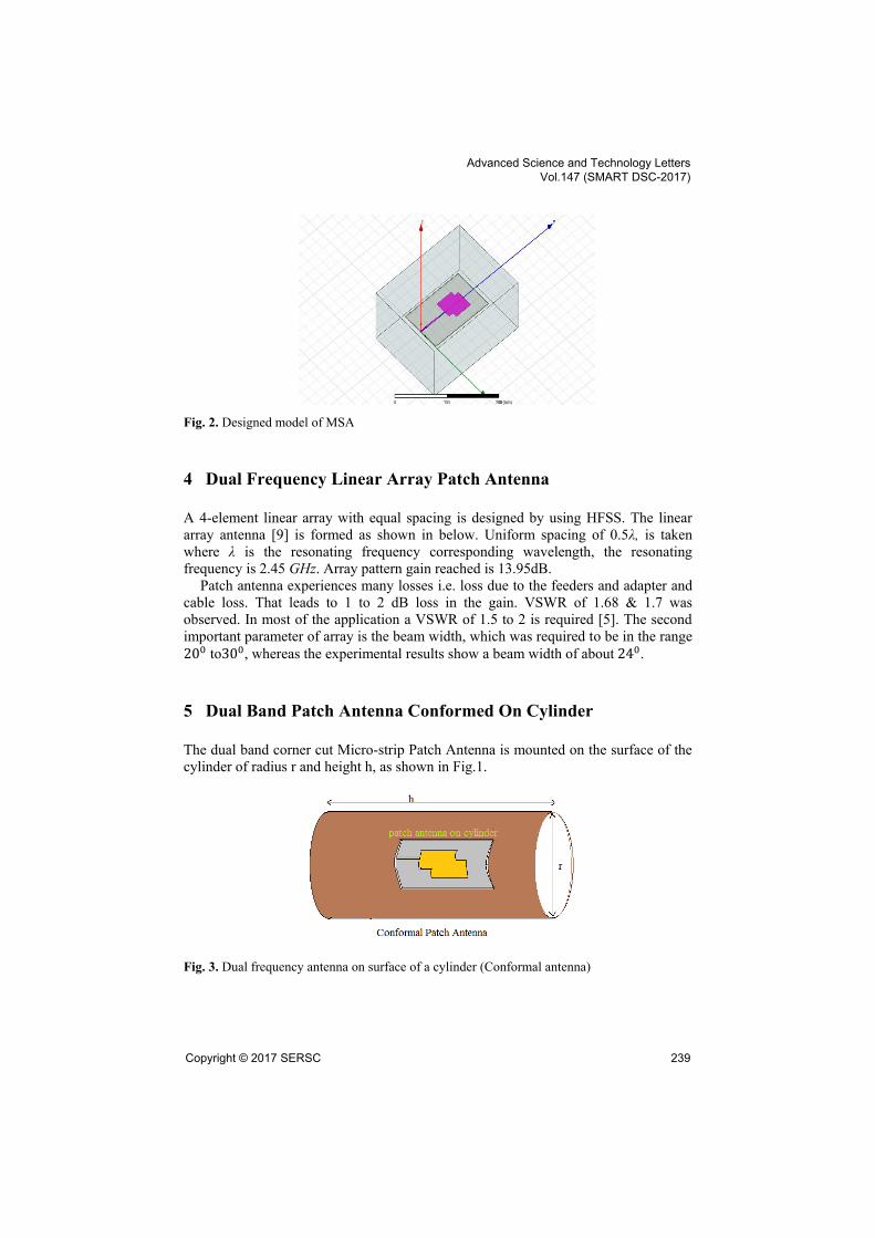
Fig. 2. Designed model of MSA
4 Dual Frequency Linear Array Patch Antenna
A 4-element linear array with equal spacing is designed by using HFSS. The linear
array antenna [9] is formed as shown in below. Uniform spacing of 0.5λ, is taken
where λ is the resonating frequency corresponding wavelength, the resonating
frequency is 2.45 GHz. Array pattern gain reached is 13.95dB.
Patch antenna experiences many losses i.e. loss due to the feeders and adapter and
cable loss. That leads to 1 to 2 dB loss in the gain. VSWR of 1.68 & 1.7 was
observed. In most of the application a VSWR of 1.5 to 2 is required [5]. The second
important parameter of array is the beam width, which was required to be in the range
200 to300, whereas the experimental results show a beam width of about 240.
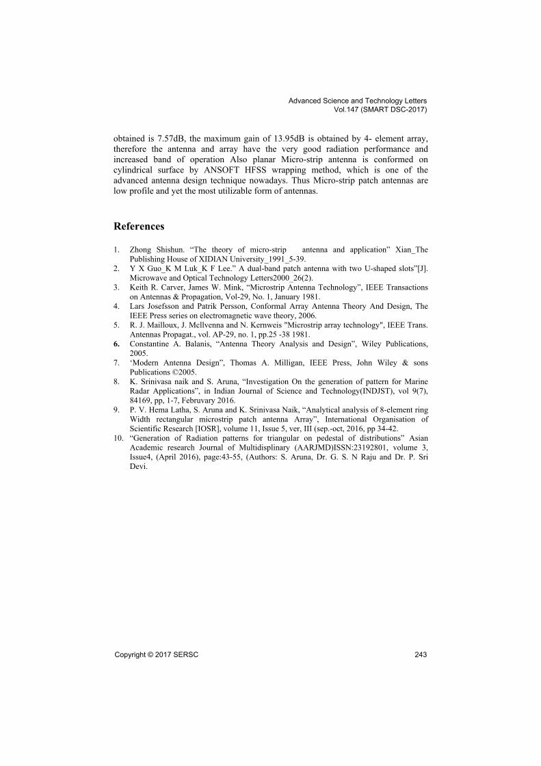
5 Dual Band Patch Antenna Conformed On Cylinder
The dual band corner cut Micro-strip Patch Antenna is mounted on the surface of the
cylinder of radius r and height h, as shown in Fig.1.
Fig. 3. Dual frequency antenna on surface of a cylinder (Conformal antenna)
Advanced Science and Technology Letters Vol.147 (SMART DSC-2017)
Copyright © 2017 SERSC 239

6 Simulated Results
Advanced Science and Technology Letters Vol.147 (SMART DSC-2017)
240 Copyright © 2017 SERSC

Advanced Science and Technology Letters Vol.147 (SMART DSC-2017)
Copyright © 2017 SERSC 241

Table 1. Optimized antenna parameters
Micro-strip patch antenna Dimension after parametric analysis(in mm)
Patch antenna
Width 45
Length 48
Quarter wave transformer
Width 0.822
Length 20.94
Transmission Feed line
Width 3.059
Length 40.8805
7 Conclusion
The rectangular narrow band patch antenna is transmitted into the Dual band patch
antenna by creating cut-down squares at symmetrical corners therefore the band of
operation is increased and also by optimizing antenna parameters the unit gain value
Advanced Science and Technology Letters Vol.147 (SMART DSC-2017)
242 Copyright © 2017 SERSC
obtained is 7.57dB, the maximum gain of 13.95dB is obtained by 4- element array,
therefore the antenna and array have the very good radiation performance and
increased band of operation Also planar Micro-strip antenna is conformed on
cylindrical surface by ANSOFT HFSS wrapping method, which is one of the
advanced antenna design technique nowadays. Thus Micro-strip patch antennas are
low profile and yet the most utilizable form of antennas.
References
1. Zhong Shishun. “The theory of micro-strip antenna and application” Xian_The
Publishing House of XIDIAN University_1991_5-39.
2. Y X Guo_K M Luk_K F Lee.” A dual-band patch antenna with two U-shaped slots”[J].
Microwave and Optical Technology Letters2000_26(2).
3. Keith R. Carver, James W. Mink, “Microstrip Antenna Technology”, IEEE Transactions
on Antennas & Propagation, Vol-29, No. 1, January 1981.
4. Lars Josefsson and Patrik Persson, Conformal Array Antenna Theory And Design, The
IEEE Press series on electromagnetic wave theory, 2006.
5. R. J. Mailloux, J. Mcllvenna and N. Kernweis "Microstrip array technology", IEEE Trans.
Antennas Propagat., vol. AP-29, no. 1, pp.25 -38 1981.
6. Constantine A. Balanis, “Antenna Theory Analysis and Design”, Wiley Publications,
2005.
7. ‘Modern Antenna Design”, Thomas A. Milligan, IEEE Press, John Wiley & sons
Publications © 2005.
8. K. Srinivasa naik and S. Aruna, “Investigation On the generation of pattern for Marine
Radar Applications”, in Indian Journal of Science and Technology(INDJST), vol 9(7),
84169, pp, 1-7, Februvary 2016.
9. P. V. Hema Latha, S. Aruna and K. Srinivasa Naik, “Analytical analysis of 8-element ring
Width rectangular microstrip patch antenna Array”, International Organisation of
Scientific Research [IOSR], volume 11, Issue 5, ver, III (sep.-oct, 2016, pp 34-42.
10. “Generation of Radiation patterns for triangular on pedestal of distributions” Asian
Academic research Journal of Multidisplinary (AARJMD)ISSN:23192801, volume 3,
Issue4, (April 2016), page:43-55, (Authors: S. Aruna, Dr. G. S. N Raju and Dr. P. Sri
Devi.
Advanced Science and Technology Letters Vol.147 (SMART DSC-2017)
Copyright © 2017 SERSC 243