Studio 5000 View Designer Getting Started Guide (9324 ... · The examples and diagrams in this...
22
Studio 5000 View Designer Getting Started Guide Publication 9324-QS001A-EN-D - September 2015 This publication is not superseded by another version
Transcript of Studio 5000 View Designer Getting Started Guide (9324 ... · The examples and diagrams in this...

Studio 5000 View Designer Getting Started Guide Publication 9324-QS001A-EN-D - September 2015
This publication is not superseded by another version

Important user information
Read this document and the documents listed in the additional resources section about installation, configuration, and operation of this equipment before you install, configure, operate, or maintain this product. Users are required to familiarize themselves with installation and wiring instructions in addition to requirements of all applicable codes, laws, and standards.
Activities including installation, adjustments, putting into service, use, assembly, disassembly, and maintenance are required to be carried out by suitably trained personnel in accordance with applicable code of practice. If this equipment is used in a manner not specified by the manufacturer, the protection provided by the equipment may be impaired.
In no event will Rockwell Automation, Inc. be responsible or liable for indirect or consequential damages resulting from the use or application of this equipment.
The examples and diagrams in this manual are included solely for illustrative purposes. Because of the many variables and requirements associated with any particular installation, Rockwell Automation, Inc. cannot assume responsibility or liability for actual use based on the examples and diagrams.
No patent liability is assumed by Rockwell Automation, Inc. with respect to use of information, circuits, equipment, or software described in this manual.
Reproduction of the contents of this manual, in whole or in part, without written permission of Rockwell Automation, Inc., is prohibited.
Throughout this manual, when necessary, we use notes to make you aware of safety considerations.
WARNING: Identifies information about practices or circumstances that can cause an explosion in a hazardous environment, which may lead to personal injury or death, property damage, or economic loss.
ATTENTION: Identifies information about practices or circumstances that can lead to personal injury or death, property damage, or economic loss. Attentions help you identify a hazard, avoid a hazard, and recognize the consequence
Important: Identifies information that is critical for successful application and understanding of the product.
Labels may also be on or inside the equipment to provide specific precautions.
SHOCK HAZARD: Labels may be on or inside the equipment, for example, a drive or motor, to alert people that dangerous voltage may be present.
BURN HAZARD: Labels may be on or inside the equipment, for example, a drive or motor, to alert people that surfaces may reach dangerous temperatures.
ARC FLASH HAZARD: Labels may be on or inside the equipment, for example, a motor control center, to alert people to potential Arc Flash. Arc Flash will cause severe injury or death. Wear proper Personal Protective Equipment (PPE). Follow ALL Regulatory requirements for safe work practices and for Personal Protective Equipment (PPE).
Allen-Bradley, Rockwell Software, Rockwell Automation, and TechConnect are trademarks of Rockwell Automation, Inc.
Trademarks not belonging to Rockwell Automation are property of their respective companies.

Publication 9324-QS001A-EN-D - September 2015 3
Table of contents
Create a project .......................................................................................................... 5 Add a controller reference ....................................................................................... 6 Select a target HMI device for a new project ....................................................... 7 Project Explorer.......................................................................................................... 8 View the default content of a project .................................................................... 8 Create a screen ............................................................................................................ 9 Add a graphic element to a screen ....................................................................... 10 Change the properties of a graphic element ...................................................... 10 Bind a property to a data item .............................................................................. 11 Trigger an action on a Button Behavior event ................................................. 12 Create a shortcut to an existing screen ............................................................... 14 Download a runtime application to an HMI device ....................................... 15 Open a screen ........................................................................................................... 17 Settings screen.......................................................................................................... 18 Legal Notices ............................................................................................................ 19
Studio 5000 View Designer Getting Started Guide


Publication 9324-QS001A-EN-D - September 2015 5
Studio 5000 View Designer Getting Started Guide
Get started creating a runtime application:
Create a project on page 5
Select a target HMI device for a new project on page 7
Add a controller reference on page 6
View the Project Explorer on page 8
View default content of a project on page 8
Create a screen on page 9
Add a graphic element to a screen on page 10
Change the properties of a graphic element on page 10
Bind a property to a data item on page 11
Trigger an action on a Button Behavior event on page 12
Create a shortcut to an existing screen on page 14
Download a runtime application to an HMI device on page 15
Open a screen on page 17
Use the Settings screen to configure the HMI device on page 18
The first step towards building your runtime application is creating a project. A View Designer project includes the screens you create, controller references, and information about the target HMI device. The project is stored in a file with a .vpd extension.
Before you begin:
Close any open project. You cannot create a project if another project is open. You do not need to close projects that are open in other instances of View Designer. However, it is recommended that you have no more than three instances of View Designer running at one time.
To create a project:
1. On the Menu bar, click FILE > New Project.
2. Select the appropriate HMI device. The screens in the project represent the physical size of the screen on the selected HMI device.
3. In the Name box, type a name for the project, and click Finish.
Create a project

Studio 5000 View Designer Getting Started Guide
6 Publication 9324-QS001A-EN-D - September 2015
The name must contain only numbers, letters, and underscores.
The name must not begin with a number, contain spaces, have more than one underscore in a row, or end with an underscore.
The name must not be a reserved keyword:
Keyword Keyword Keyword Keyword Keyword Keyword Keyword Keyword
ABS ACOS ACS AND ASIN ASN ATAN ATN
BEGIN_NT_RUNG BY CASE COS DEG DEG DO ELSE
ELSIF END_CASE END_FOR END_IF END_NT_RUNG END_REPEAT END_WHILE EXIT
FOR FRD GOTO IF IMAGES LN LOG MOD
NOT OF OR PROFILES RAD REPEAT RETURN SIN
SQR SQRT TAN THEN THIS TO TOD TRN
TRUNC UNTIL WHILE XOR
View Designer creates the project and displays its contents in the Project Explorer tab. The project contains a default screen named Screen_001, which is open.
The Project Properties dialog box is also open. Use the References tab to add the controller references for this project. A controller reference is a connection from the View Designer project file (.vpd) to a Logix Designer project file (.acd).
A controller reference is a connection to a Logix Designer project file (.acd) from a View Designer project file (.vpd). The connection automatically synchronizes data between a Logix Designer project file (.acd) and View Designer project file (.vpd).
Important: Logix controllers and project files must be version 27 or later. See the release notes for compatible controllers.
To add a controller reference:
1. On the Project Properties dialog box, click the References tab.
2. In the Name box, type a unique name for the controller reference. The controller reference name cannot be the same as the project name.
3. Next to the Logix project box, click Browse and select a Logix Designer project file (.acd). You can also type the path of the file.
4. Next to the HMI to controller path box, click Browse and select the controller that is running the selected Logix Designer project file (.acd). You can also type the IP address of the controller. Select a controller only from an Ethernet network.
Add a controller reference

Studio 5000 View Designer Getting Started Guide
Publication 9324-QS001A-EN-D - September 2015 7
5. In the Slot box, select the slot number of the controller that you want to reference. If you browsed to the controller in the previous step, the slot number is already selected.
6. Click Apply to save your changes and remain on the Project Properties dialog box, or click OK to save your changes and close the Project Properties dialog box.
Tip: When you are browsing for a controller, the OK button is available only when you select a View Designer-compatible device.
The screens in a project represent the physical size of the HMI device selected for the project. You must select a target HMI device before you can download the runtime application to the HMI device.
Before you begin:
Create a new project. When you click Finish on the New Project dialog box, the Project Properties dialog box opens.
To select a target HMI device:
1. On the Project Properties dialog box, click the Application tab.
2. In the Location box, select from a list of the most recently used location, or click Browse and select the HMI device to which the runtime application will be downloaded. When you browse for an HMI device, the OK button is available only when you select a View Designer-compatible device.
3. In the Type box, click Browse .
4. On the Select HMI Device dialog box, select the appropriate HMI device type. By default, this is set to the HMI device type you specify in the New Project dialog box.
5. Click OK to close the Select HMI Device dialog box.
6. Click Apply to save your changes and remain on the Project Properties dialog box, or click OK to save your changes and close the Project Properties dialog box.
Important: Use the Screen Scaling options on the Application tab if you change the HMI device type after you create screen content.
Select a target HMI device for a new project

Studio 5000 View Designer Getting Started Guide
8 Publication 9324-QS001A-EN-D - September 2015
On the Menu bar, click VIEW > Project Explorer.
The Project Explorer displays the contents of a View Designer project in tree form. The root-level project folder contains the project name and default folders -- Navigation Menu, User-Defined Screens, and Predefined Screens. These folders contain the items of the project, including default content. Project items include:
Default Folder Screens Shortcuts Popups Folders Default Project Screens and Popups
Navigation Menu
User-Defined Screens
Predefined Screens
The content and its order in the Navigation Menu folder are displayed as menu items in the Navigation menu on the HMI device. The shortcuts in the Navigation Menu folder are based on user-defined screens or the Settings, Alarm Summary, and Alarm Manager predefined screens.
Use the Project Explorer to:
Browse and organize the contents of a project.
Add screens, shortcuts, popups, and folders to a project.
Open, rename, and delete screens, shortcuts, popups, and folders.
Create navigation for the user on the HMI device.
Display the properties of a project, such as controller references and the target HMI device.
Verify a project.
Rename a project.
Right-click an item in the Project Explorer to see a list of actions you can perform.
The Predefined Screens folder in the Project Explorer contains default screens, popups, and a Banner item for each project.
To view default content of a project:
1. On the Menu bar, click VIEW > Project Explorer.
Project Explorer
View the default content of a project

Studio 5000 View Designer Getting Started Guide
Publication 9324-QS001A-EN-D - September 2015 9
2. View the contents of the Predefined Screens folder:
Banner. By default, the Banner appears at the top of each project screen. It displays date and time, active and unacknowledged alarm indicators, controller diagnostic, and network diagnostic information. It also provides buttons to navigate to the Alarm Summary, log on and log off the project, move backward and forward through navigation history, and display the Navigation menu at the bottom of the HMI device.
Settings. This screen provides a menu of options to configure settings for the HMI device. By default, you can access the Settings screen through the Navigation menu on the HMI device. The options on the Settings screen open the popups listed under the screen in the Predefined Screens folder. These popups perform tasks to configure HMI device settings.
AlarmSummary. This screen displays the Alarm Summary, a list of alarms that are in "interesting" states or that require attention. For example, the Alarm Summary lists alarms that are In Alarm and Unacknowledged. By default, you can access the AlarmSummary screen through the System Banner or the Navigation menu on the HMI device.
AlarmManager. This screen displays the Alarm Manager, a list of all alarms regardless of their state. Alarms listed in the Alarm Manager include all of the conditions for a given alarm. By default, you can access the AlarmManager screen through the Navigation menu or the Alarm Summary on the HMI device.
Tips: To add or remove information and functionality from predefined items, change the content of predefined screens, popups, and the Banner item as you would any other screen. Do not remove content you need to configure your HMI device.
To restore the default content of a predefined screen, popup, or the Banner item, remove any remaining content from the revised item, open an unchanged version of the item in another project, and copy and paste the default content to your item.
You can drag the Settings, AlarmSummary, and AlarmManager screens to the Navigation Menu folder in the Project Explorer. This creates a shortcut for the screen and makes it appear in the Navigation Menu. By default, these items are already in the Navigation Menu.
A screen in View Designer contains the items to appear on the screen on the HMI device. After you add a screen to a project, build the content and design the behavior you want to see on the HMI device. A project can contain up to 50 screens, including popups.
Create a screen

Studio 5000 View Designer Getting Started Guide
10 Publication 9324-QS001A-EN-D - September 2015
To create a screen:
In the Project Explorer, right-click the User-Defined Screens folder and click New Screen. A screen named Screen_002 or increment number is added to the folder.
Tip: After adding the screen, create content for it by adding graphic elements.
Add up to 500 graphic elements, including Add-On Graphics and image graphic elements, to a screen. After you add a graphic element to a screen, you can change its appearance and behavior by changing its properties, binding it to a tag, and associating it with an animation or event.
To add a graphic element to a screen:
1. In the Toolbox, click a category to display the graphic elements in that category.
2. Drag a graphic element onto the screen. You can also double-click a graphic element in the Toolbox to add it to the center of the screen. If a graphic element is already selected on the screen, the new graphic element is placed on top of it.
Important: If you place a lot of content on your screens, such as large images, the HMI device can run out of memory. The Properties tab displays the size of the image. Use the predefined HMI Device screen to monitor memory usage. If the HMI device runs out of memory while it is running an application, it restarts and provides an error message indicating that an out-of-memory condition occurred.
If the computer running View Designer runs out of memory, View Designer shuts down and provides a message indicating that an out-of-memory condition occurred. View Designer retains the last saved version of the project.
Tips: Add a graphic element that is used in a different project by copying and pasting it.
If you know the name or type of graphic element, use the search feature for the Toolbox.
The name of each graphic element ends with a number that increments by one each time you add an instance of that element. For example, TextDisplay_002 indicates a second instance of the Text Display graphic element on the screen.
Change the attributes of a graphic element, such as color and size, using the Properties tab in the Properties window.
To change the properties of a graphic element:
1. On the screen or in the Graphic Explorer, click the graphic element.
Add a graphic element to a screen
Change the properties of a graphic element

Studio 5000 View Designer Getting Started Guide
Publication 9324-QS001A-EN-D - September 2015 11
To select multiple graphic elements, press and hold Ctrl while you click each element.
To select all of the graphic elements, press Ctrl+A.
2. In the Properties window, click the Properties tab to display the properties for the selected graphic element.
3. Change any or all of the properties:
Type or select a value.
Bind the property to a data item.
When the property of a graphic element or screen is bound to a data item, it receives its value dynamically. A data item can be a tag, an extended property of a tag, a property of a graphic element or screen, or an expression. If a property can be
bound, a Binding button appears next to the property name when you point to it.
To bind a property to a data item:
1. Select the graphic element.
You can also select multiple graphic elements to bind a common property of each element simultaneously.
2. Expand the categories in the Properties tab to locate the property to bind to a tag.
3. Point to the property box until the Binding button appears, click it, and click Bind property to item.
4. Click Browse to open the Tag Browser, and select a data item from the Tag Browser, or enter an expression.
Bind a property to a data item

Studio 5000 View Designer Getting Started Guide
12 Publication 9324-QS001A-EN-D - September 2015
To create or edit lengthy or complex expressions, click Open
Expression Editor .
To bind to a property of a graphic element, use the syntax ElementName.PropertyName.
Important: When binding to a property that consists of a list (for example, FontName, Format, Rounding) you must use a string tag that exactly matches the text of the item in the list. For example, to bind and use the Saturday Sans font, the string must contain Saturday Sans ICG to be considered an exact match. If the value of the tag does not match a value in the list, the first item in the list is used.
If you create an alias for a property that is already bound to a data item, all instances of the alias are bound to that same data item.
You can bind graphic element properties only to properties of graphic elements that are on the same screen, popup, or System Banner.
When you change the value of a graphic element property on a screen by binding to it, the changed value is not retained if you close and re-open the screen.
When you change the value of a graphic element property on a popup by binding to it, the changed value is retained if you close and re-open the popup.
When binding tags to numeric properties, keep the following in mind:
If an numeric property is bound to a REAL tag, the resulting value is rounded.
If a numeric property is bound to a STRING tag or property source, the resulting value is truncated.
Add a Button Behavior event to a graphic element to have the graphic element perform typical button actions. Button Behavior events apply typical button behaviors to a graphic element by performing pre-configured commands. For example, you can create a Button Behavior event that sets a tag to 1 on a touch press and sets the same tag to 0 on a touch release. This is useful for creating events for a button to start and stop a conveyor belt. Button behavior events include internal commands that you do not have to configure. You can have only one Button Behavior event per graphic element.
To make a graphic element behave like a button:
1. On the screen, right-click the graphic element and then click Button Behavior. You can add a Button Behavior event for the selected graphic element through the Events tab of the Properties window.
2. Select the desired behavior.
Behavior type Description
Set a tag to 1 on release Sets the value of the selected tag to 1 when you release the button. To configure this command, in the Tag box, enter or browse to select the tag.
Trigger an action on a Button Behavior event

Studio 5000 View Designer Getting Started Guide
Publication 9324-QS001A-EN-D - September 2015 13
Set a tag to 0 on release Sets the value of the selected tag to 0 when you release the button. To configure this command, in the Tag box, enter or browse to select the tag.
Set a tag to 1 on press, 0 on release Sets the value of the selected tag to 1 when you press the button, and sets the value to 0 when you release the button. You can select a minimum hold time for this button behavior. To configure this command, in the Tag box, enter or browse to select the tag. For momentary button behaviors, you can keep the button pressed for a minimum length of time. The button stays pressed even if you release the button before the minimum hold time. To set a minimum hold time for the momentary button, select the Minimum Hold Time box, and then select a minimum hold time. You cannot press the button again until the minimum hold time expires. If a screen or popup containing the button closes before the hold time expires, the hold time is reset. The minimum hold time does not support binding.
Set a tag to 0 on press, 1 on release Sets the value of the selected tag to 0 when you press the button, and sets the value to 1 when you release the button. You can select a minimum hold time for this button behavior. To configure this command, in the Tag box, enter or browse to select the tag. For momentary button behaviors, you can keep the button pressed for a minimum length of time. The button stays pressed even if you release the button before the minimum hold time. To set a minimum hold time for the momentary button, select the Minimum Hold Time box, and then select a minimum hold time. You cannot press the button again until the minimum hold time expires. If a screen or popup containing the button closes before the hold time expires, the hold time is reset. The minimum hold time does not support binding.
Toggle a tag on release Toggles the value of the selected BOOL tag from 0 to 1, or from 1 to 0, when you release the button. To configure this command, in the Tag box, enter or browse to select the BOOL tag.
Write to a tag on release Writes a value to the selected tag when you release the button. You can specify the value with a number, a tag, or an expression. To configure this command, in the Tag box, enter or browse to select the tag. In the expression box, create the expression value to write to the tag when you release the button.
Incrementally change a tag on release Increments the value of the selected tag when you release the button. You can specify the value with a number, a tag, or an expression. To configure this command, in the Tag box, enter or browse to select the tag. In the By box, create the expression value by which to increment the tag when you release the mouse button. The increment can be either negative or positive.
Logix HMIBC set to 1 on press, 0 on release Uses high priority communication to set the value of the selected HMIBC tag's .ButtonState member to 1 when you press the button, and to 0 when you release the button. To configure this command, in the HMIBC Tag box, select an HMIBC type tag. The Tag Browser filters HMIBC type tags from the Logix Designer project file (.acd). Select the HMIBC type tag only. When you create an HMIBC button using the Logix HMIBC set to 1 on press, 0 on release Button Behavior option, you use the .ButtonState member of the HMIBC tag automatically.
Logon on release Open the Log On dialog box when you release the button. When you log on to the HMI device, you see only the items to which your assigned role is granted access. When the Log On dialog box opens, any open popup closes.

Studio 5000 View Designer Getting Started Guide
14 Publication 9324-QS001A-EN-D - September 2015
Logoff on release Logs the current user off the HMI device. This logs on the Guest user role automatically. You then see only the items to which the Guest role is granted access.
Open popup on release Opens a specific popup when the event occurs. To configure this command, in the Open Popup box, navigate to and select the popup the event is to open. The popups listed exist in the User-Defined Screens and Predefined Screens folders of the Project Explorer. Only popups are listed when you select the Popup Open command. You can open only one popup at a time on the HMI device. When a popup opens, any previously open popup closes.
Close popup on release Closes the popup on the HMI device when the event occurs. You can have only one popup at a time open on the HMI device.
Navigate to screen on release Opens the specified screen or shortcut when you release the button. To configure this command, in the Navigate To box, select the shortcut or screen the event is to open. You can navigate to the contents of the Navigation Menu, User-Defined Screens, and Predefined Screens folders of the Project Explorer.
Navigate backward on release Navigates back in history to open the screen you opened using either the Navigation menu or a Screen Navigate command. You erase your navigation history when you log off the HMI device.
Navigate forward on release Navigates forward in history to open the screen you opened using either the Navigation menu or a Screen Navigate command. You erase your navigation history when you log off the HMI device.
Show Navigation Menu on release Opens the Navigation menu on the HMI device screen when you release the button.
3. To have the event occur even if you do not first tab to set focus on the graphic element, clear the Requires Focus check box.
4. For momentary button behaviors (Set a tag to 1 on press, 0 on release and Set a tag to 0 on press, 1 on release), check the Always Trigger Release Event box.
Tips: If you select the behavior type after entering a tag, the selected tag remains in the Tag box. This occurs unless you select the HMIBC behavior or a navigation behavior. For example, if you select Tag_1 for the Set a tag to 1 on release behavior and change to Set a tag to 0 on release, Tag_1 remains configured for the new selection.
By default, Button Behavior events work with touch only. To have a key press activate the Button Behavior event, in the Key box, select an HMI device key. The event triggers when press the selected key or touch the graphic element.
Clear the Always Trigger Release Event check box to not commit to a press action and allow yourself to slide finger off the graphic element without triggering the release event.
Create a shortcut to a screen in the Project Explorer to create a link to the existing screen. From the shortcut, you can change any properties you defined for the screen. The values of these properties are passed from the shortcut to the screen so that the screen displays different data.
A project can contain up to 50 screens and popups but up to 200 shortcuts. You may end up creating many shortcuts in order to reuse a single screen and pass
Create a shortcut to an existing screen

Studio 5000 View Designer Getting Started Guide
Publication 9324-QS001A-EN-D - September 2015 15
different values to the screen. Shortcuts appear in the Navigation Menu folder of the Project Explorer and in the Navigation menu on the HMI device.
To create a shortcut:
In the Project Explorer, use one of these methods:
In the User-Defined Screens folder or the Predefined Screens folder, right-click the screen on which you want to base the shortcut, and click New Shortcut. The new shortcut appears in the Navigation Menu folder. The new shortcut is given a default name that is identical to the screen name. You can move the new shortcut within the Navigation Menu folder and its subfolders.
Drag a screen from the User-Defined Screens folder or the Predefined Screens folder to the Navigation Menu folder.
Right-click the Navigation Menu folder or one of its subfolders, and click New Shortcut. The New Shortcut dialog box opens.
a. In the Name box, type a unique name for the shortcut and click OK. Shortcuts with identical names in the same folder are appended with an increment number.
b. Select Linked to an existing screen.
c. Navigate to select the screen that defines the shortcut, and click OK. The shortcut appears in the selected location in the Navigation Menu folder.
Tips: You can create a shortcut to a new screen from the New Shortcut dialog box.
You cannot create a shortcut to a shortcut.
If you do not want a shortcut to appear in the Navigation menu on the HMI device screen, delete the shortcut.
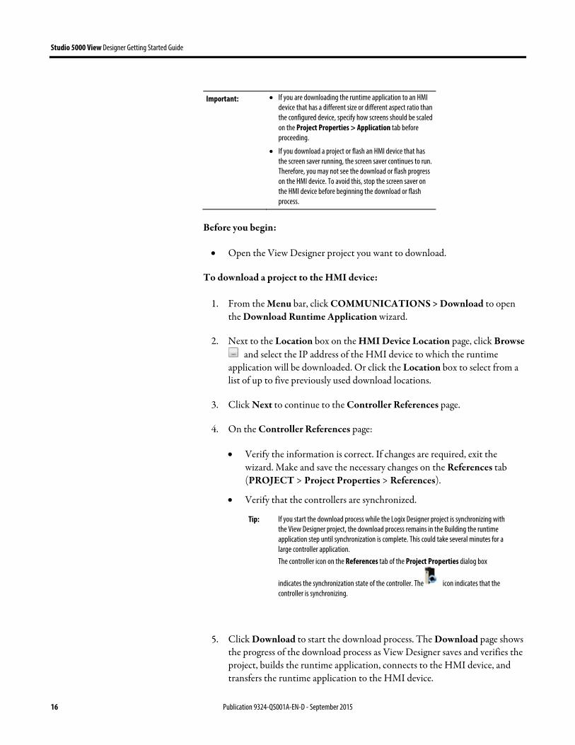
Use the Download Runtime Application wizard to transfer a runtime application to an HMI device.
Download a runtime application to an HMI device
Studio 5000 View Designer Getting Started Guide
16 Publication 9324-QS001A-EN-D - September 2015
Important: If you are downloading the runtime application to an HMI device that has a different size or different aspect ratio than the configured device, specify how screens should be scaled on the Project Properties > Application tab before proceeding.
If you download a project or flash an HMI device that has the screen saver running, the screen saver continues to run. Therefore, you may not see the download or flash progress on the HMI device. To avoid this, stop the screen saver on the HMI device before beginning the download or flash process.
Before you begin:
Open the View Designer project you want to download.
To download a project to the HMI device:
1. From the Menu bar, click COMMUNICATIONS > Download to open the Download Runtime Application wizard.
2. Next to the Location box on the HMI Device Location page, click Browse and select the IP address of the HMI device to which the runtime
application will be downloaded. Or click the Location box to select from a list of up to five previously used download locations.
3. Click Next to continue to the Controller References page.
4. On the Controller References page:
Verify the information is correct. If changes are required, exit the wizard. Make and save the necessary changes on the References tab (PROJECT > Project Properties > References).
Verify that the controllers are synchronized.
Tip: If you start the download process while the Logix Designer project is synchronizing with the View Designer project, the download process remains in the Building the runtime application step until synchronization is complete. This could take several minutes for a large controller application. The controller icon on the References tab of the Project Properties dialog box
indicates the synchronization state of the controller. The icon indicates that the controller is synchronizing.
5. Click Download to start the download process. The Download page shows the progress of the download process as View Designer saves and verifies the project, builds the runtime application, connects to the HMI device, and transfers the runtime application to the HMI device.

Studio 5000 View Designer Getting Started Guide
Publication 9324-QS001A-EN-D - September 2015 17
If View Designer encounters a problem, an error message displays at the point it occurred and the process stops. When invalid tags or expressions are found during project verification, the Errors window opens to display a list of the warnings or errors associated with the tags or expressions. All errors must be resolved before the runtime application can be downloaded to the HMI device.
Open any screen to which your assigned role has security rights. When you open a screen, an overlay dims the current screen, indicating you can no longer interact with the screen. When the new screen opens, you can interact with the screen immediately, even if the overlay from the previous screen shows briefly, or the content of the new screen is still loading.
Screens to which your assigned role does not have security rights do not appear in the Navigation menu on the HMI device. By default, the Home screen of the project opens on the HMI device. The Home screen and the security rights of your assigned role are specified in Studio 5000 View Designer. To return to the Home screen after you open a different screen, in the Navigation menu, tap Home .
To open a screen:
1. In the System Banner at the top of the HMI device screen, tap Navigation
. You can also press the Navigation button on the HMI device. Using an external keyboard, press Alt+N. The Navigation menu opens at the bottom of the screen.
2. In the Navigation menu, tap the screen item you want to open. Using an external keyboard, tab to the item and press Enter.
If the screen you want to open does not appear on the first page of items on the Navigation menu:
Tap the arrows at either end of the Navigation menu. This displays items on another page of the Navigation menu.
Tap Next and Previous in the System Banner to open the next or previous screen in the navigation history.
Tap a folder in the Navigation menu to display screens within the folder. The contents of the folder appears in an upper row. If the desired menu item appears in a subfolder, tap the subfolder. The current folder path, in the form of breadcrumbs, appears in the upper row. Tap the Back icon to the left of the breadcrumbs to navigate back a folder. If you do not select a folder in the bottom row, an upper row
Open a screen

Studio 5000 View Designer Getting Started Guide
18 Publication 9324-QS001A-EN-D - September 2015
does not appear. If you select an empty folder in the bottom row, the upper row appears empty.
Tip: If you are using an external keyboard, use the following keys to navigate the Navigation menu: Next item. Press the right arrow and Enter.
Previous item. Press the left arrow and Enter.
First item. Press Home and Enter.
Last item. Press End and press Enter.
Next page of menu items. Press Page Down.
Previous page of menu items. Press Page Up.
1. On the System Banner at the top of the screen, or on the physical HMI
device, press Navigation . On an external keyboard, press Alt/n.
2. On the Navigation menu at the bottom of the screen, tap Settings.
3. To select the menu item using an external keyboard, tab to the item and press Enter. The Settings screen opens.
Use the Settings screen to view and change HMI device and system-wide settings. On the Settings screen, select an option to perform its related tasks:
Option: Tasks:
Network Specify IP settings
Specify Ethernet port settings
View network diagnostics
Display Adjust the HMI device screen brightness
Turn on the screen saver
Set the brightness and delay for the screen saver
Calibrate the screen to respond to touch accurately
HMI Device Change the name of the HMI device
Specify if project downloads and firmware updates are allowed
View catalog and firmware numbers
View diagnostic information
Reboot the HMI device
Date and Time Set the date and time of the HMI device
Set the time zone of the HMI device
Controllers View controller reference and status information
View controller diagnostics
Troubleshooting Import a troubleshooting profile
Export a troubleshooting log
Settings screen

Studio 5000 View Designer Getting Started Guide
Publication 9324-QS001A-EN-D - September 2015 19
Copyright notice
© 2015 Rockwell Automation, Inc. All rights reserved. Printed in USA.
This document and any accompanying Rockwell Software products are copyrighted by Rockwell Automation, Inc. Any reproduction and/or distribution without prior written consent from Rockwell Automation, Inc. is strictly prohibited. Please refer to the license agreement for details.
End User License Agreement (EULA)
You can view the Rockwell Automation End-User License Agreement ("EULA") by opening the License.rtf file located in your product's install folder on your hard drive.
Warranty
This product is warranted in accordance with the product license. The product’s performance may be affected by system configuration, the application being performed, operator control, maintenance, and other related factors. Rockwell Automation is not responsible for these intervening factors. The instructions in this document do not cover all the details or variations in the equipment, procedure, or process described, nor do they provide directions for meeting every possible contingency during installation, operation, or maintenance. This product’s implementation may vary among users.
This document is current as of the time of release of the product; however, the accompanying software may have changed since the release. Rockwell Automation, Inc. reserves the right to change any information contained in this document or the software at any time without prior notice. It is your responsibility to obtain the most current information available from Rockwell when installing or using this product.
Environmental compliance
Rockwell Automation maintains current product environmental information on its website at http://www.rockwellautomation.com/rockwellautomation/about-us/sustainability-ethics/product-environmental-compliance.page
Legal Notices

Studio 5000 View Designer Getting Started Guide
20 Publication 9324-QS001A-EN-D - September 2015
Contact Rockwell
Customer Support Telephone — 1.440.646.3434 Online Support — http://www.rockwellautomation.com/support/

Studio 5000 View Designer Getting Started Guide
Publication 9324-QS001A-EN-D - September 2015 21

Publication 9324-QS001A-EN-D - September 2015
This publication is not superseded by another version Copyright © 2015 Rockwell Automation, Inc. All rights reserved. Printed in the U.S.A.
Rockwell Automation support
Rockwell Automation provides technical information on the web to assist you in using its products. At http://www.rockwellautomation.com/support you can find technical and application notes, sample code, and links to software service packs. You can also visit our Support Center at https://rockwellautomation.custhelp.com for software updates, support chats and forums, technical information, FAQs, and to sign up for product notification updates.
In addition, we offer multiple support programs for installation, configuration, and troubleshooting. For more information, contact your local distributor or Rockwell Automation representative, or visit http://www.rockwellautomation.com/services/online-phone.
Installation assistance
If you experience a problem within the first 24 hours of installation, review the information that is contained in this manual. You can contact Customer Support for initial help in getting your product up and running.
United States or Canada 1.440.646.3434
Outside United States or Canada Use the Worldwide Locator available at http://www.rockwellautomation.com/locations, or contact your local Rockwell Automation representative.
New product satisfaction return
Rockwell Automation tests all of its products to ensure that they are fully operational when shipped from the manufacturing facility. However, if your product is not functioning and needs to be returned, follow these procedures.
United States Contact your distributor. You must provide a Customer Support case number (call the phone number above to obtain one) to your distributor to complete the return process.
Outside United States Please contact your local Rockwell Automation representative for the return procedure.
Documentation feedback
Your comments will help us serve your documentation needs better. If you have any suggestions on how to improve this document, complete the feedback form, publication RA-DU002.