Studies on the Reduction of Radon Plate-out on Copper ... · Studies on the Reduction of Radon...
33
1 Studies on the Reduction of Radon Plate-out on Copper Using Electric Fields Approved by ________________________ Dr. Stephen Sekula Rn Po Bi Tl Hg Pb SMU E-SHIELD PROJECT
Transcript of Studies on the Reduction of Radon Plate-out on Copper ... · Studies on the Reduction of Radon...

1
Studies on the Reduction of Radon Plate-out on Copper Using Electric
Fields
Approved by ________________________ Dr. Stephen Sekula
Rn
PoBi Tl
Hg
Pb
SMU E-SHIELD PROJECT
2
Studies on the Reduction of Radon Plate-out on Copper
Using Electric Fields
A Senior Thesis Presented to the Undergraduate Faculty of
the Dedman College of Southern Methodist University
in
Partial Fulfillment for the Degree of Bachelor of Science with
Distinction with a Major in Physics by
__________________________
Matthew Robert Bruemmer
April 2015

3
ACKNOWLEDGEMENTS
The Author would like to thank Professor Jodi Cooley and
Professor Stephen Sekula for their mentorship and guidance
throughout the course of this research. Their knowledge and integral
contributions to this project were vital to its success and completion.
He would also like to thank Rob Calkins, Hang Qiu, Kevin
Cieszowski, John Cotton, Tim Mulone, Lacey Porter, and Randall
Scalise for their assistance in this project. Special thanks to Mayisha
Zeb Nakib for her assistance in the project and for her support.
This material is based upon work supported by the National Science
Foundation under Grant Number (1151869), the SMU Hamilton Scholar
program and SMU Engaged Learning. Any opinions, findings, and conclusions or
recommendations expressed in this material are those of the author(s) and do not
necessarily reflect the views of the National Science Foundation.

4
Bruemmer, Matthew Robert
Studies on the Reduction of Radon Plate-out on Copper Using Electric Fields
Advisor: Dr. Stephen Sekula
Bachelor of Science with Distinction degree conferred May 2015
Senior Thesis completed April 2015
Abstract:
I investigate the ability of electric fields to reduce the capability of radon progenies to stick to
copper surfaces. Mitigating radon progeny exposure is important to the community of
experiments searching for rare processes, requiring low or no backgrounds. Background
interactions from gamma particles, neutrons, and alpha particles can mimic predicted signals
of certain dark matter or neutrino-less double beta decay processes. 222Rn is a large
contributor of background noise in the experiment when detector material or shielding
material is stored for periods of time. To understand how electric fields in storage
environments can help reduce the 222Rn plate-out, we propose to try to contaminate copper
samples protected by an electric field with radioactive sources and then measure actual
exposure levels with the XIA UltraLo 1800 alpha particle counter. The experimental set-up
includes a pressure cooker where the copper will be stored and exposed to a source of 220Rn,
which will serve as a proxy for 222Rn to shorten the length of experimental trials. The copper
will be held by a custom shelving unit made out of 3D-printed plastic, providing an
insulating framework when the electric field is applied.

5
Table of Contents
Introduction 6
Motivation 8
Radon Decay Chain 9
Figure 1 – Thorium Decay Chain 10
Figure 2 – Uranium Decay Chain 11
Calculations of the Stopping Potential 12
Experimental Setup 18
XIA UltraLo 1800 26
Results 28
Conclusions 30
References 33
6
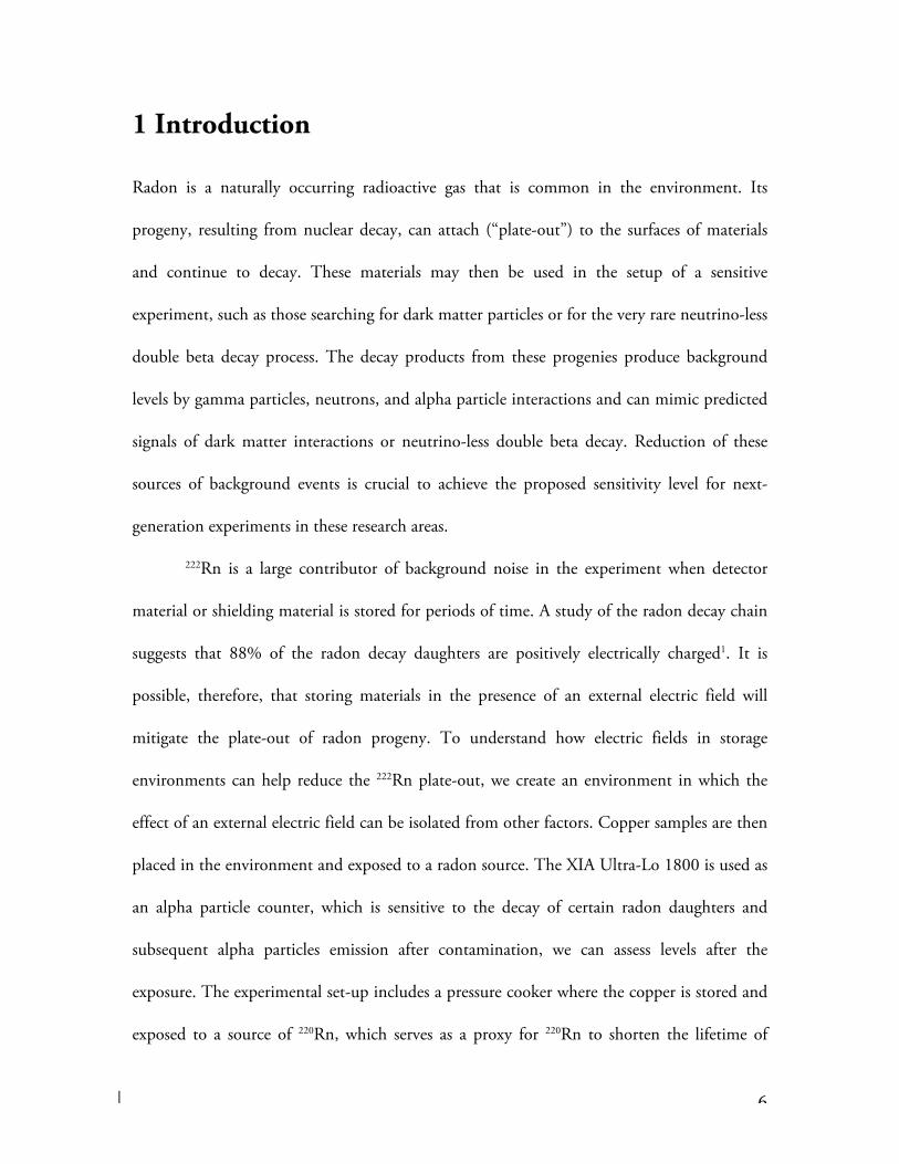
1 Introduction
Radon is a naturally occurring radioactive gas that is common in the environment. Its
progeny, resulting from nuclear decay, can attach (“plate-out”) to the surfaces of materials
and continue to decay. These materials may then be used in the setup of a sensitive
experiment, such as those searching for dark matter particles or for the very rare neutrino-less
double beta decay process. The decay products from these progenies produce background
levels by gamma particles, neutrons, and alpha particle interactions and can mimic predicted
signals of dark matter interactions or neutrino-less double beta decay. Reduction of these
sources of background events is crucial to achieve the proposed sensitivity level for next-
generation experiments in these research areas.
222Rn is a large contributor of background noise in the experiment when detector
material or shielding material is stored for periods of time. A study of the radon decay chain
suggests that 88% of the radon decay daughters are positively electrically charged1. It is
possible, therefore, that storing materials in the presence of an external electric field will
mitigate the plate-out of radon progeny. To understand how electric fields in storage
environments can help reduce the 222Rn plate-out, we create an environment in which the
effect of an external electric field can be isolated from other factors. Copper samples are then
placed in the environment and exposed to a radon source. The XIA Ultra-Lo 1800 is used as
an alpha particle counter, which is sensitive to the decay of certain radon daughters and
subsequent alpha particles emission after contamination, we can assess levels after the
exposure. The experimental set-up includes a pressure cooker where the copper is stored and
exposed to a source of 220Rn, which serves as a proxy for 220Rn to shorten the lifetime of

7
experimental trials. We use 220Rn as a proxy for 222Rn because we are not licensed to have a
222Rn source at this time. However, 220Rn sources are common and require no special
licensing beyond SMU requirements. The short half-lives of 220Rn daughters allow for a
quick experimental turn around. A custom-shelving unit made out of 3D-printed plastic
serves as an insulating support framework for the copper when the electric field is applied.

8
2 Motivation
Uranium is a common radioactive element found throughout the Earth’s crust and other
geological layers2. The decay chain of uranium is long, but a primary stage in its decay is the
production of radon, another radioactive element that is gaseous at room temperature1. Near
the end of the decay chain of the 222Rn is 210Pb, which is also radioactive and has a half-life of
22.3 years3. It is this isotope that is problematic to sensitive experiments, since it lasts a very
long time (much longer than experimentalists can wait for it to decay away) and gives off
radiation during its own decay that can create significant background for these experiments4.
Reduction of these backgrounds is crucial since radon background levels can contribute to
reducing the sensitivity of experiments that search for Weakly Interacting Massive Particles
(WIMPs).
Radon contamination mitigation is the subject of study by a variety of fields,
including the medical community (radon is a leading cause of lung cancer1), the
semiconductor industry (to prevent contamination in otherwise pure semiconductor
wafers5), and the physics community. Reduction in radon, therefore, has been a quickly
growing field of study in the last few decades. The goal in the physics community is to
quantify the reduction in radon plate-out that can be achieved by different techniques.
Achieving a significant reduction in radon contamination is crucial to advancing the
sensitivity of rare process search experiments.

9
3 Radon Decay Chain
The 238U decay chain (Fig. 2) shows 222Rn and its subsequent progenies along
with their half-lives. 238U is the most common isotope of uranium, contributing
99.284% of natural uranium. The focus of reduction efforts in the physics
community is on 222Rn, which lies in the middle of the decay chain, resulting
from the decay of 226Ra.
The State of Texas has a licensing procedure for the use of radioactive
isotopes in scientific research, as well as for other applications. The SMU
license does not currently cover the possession of a sufficient 222Rn source for
experiments (obtaining the extension to the license is a work-in-progress in the
Physics Department). However, 220Rn is available in common material and its
possession and use is covered by the existing license. For the experiments
described in this thesis, a 220Rn source is employed. The half-lives of the 220Rn
source are significantly shorter than those of the 222Rn chain, thus not a concern
for running physics experiments since it quickly decays away. Pre-1990s
camping lantern mantles are used as the source of 220Rn since its parent isotope,
232Th, is abundant6.

10
Figure 2 -‐ The 238Uranium Decay Chain Starting at
222Radon
220Rn%55%sec%
216Po%0.14%sec%
212Pb%10.6%h%
212Bi%61%m
in%
212Po%%%%0.3%%
208Pb%stable%
µs
α%
α%
β%
β%
α%
208Ti%3.1%m
in%β%
α%
Figure 1 -‐ The 238Thorium Decay Chain
Starting at 220Radon

11
222Rn$3.82$days$
218Po$3.10$m
in$
214Pb$26.8$m
in$
214Bi$19.9$m
in$
214Po$164$$
210Pb$22.3$years$
210Bi$5.01$days$
210Po$138.4$days$
206Pb$stable$
µs
α$
α$
β$
β$
α$
β$
β$
α$
Background$parCcles$of$concern$
Monitor$contam
inaCon$by$$measuring$alpha$em
ission$
Figure 2 -‐ The 238Uranium
Decay Chain
Starting at 222Radon

12
4 Calculation of the Stopping Potential
In this section there are calculations of the electric potential required to stop
radon progenies and then reverse their direction of motion under two scenarios.
The decay 220Rn è 216Po is used as the example in the calculations. These
calculations were performed before the experiment described in this thesis was
performed. They were used to motivate the equipment needed for the
experiment, and to give a rough estimate of the benefit of using an electric field
to stop radon progenies from plating-out on a sample. The stopping potential is
calculated for the general setup available for the experiments: a copper source
within a pressure cooker with an electric field applied for shielding of the
copper. The pressure cooker has a radius of four inches with a height of just
over seven inches. The copper samples being exposed are four by four inches
and are held by a copper holder of dimensions 4inx4.5inx6in. This allows for a
tight setup for the stopping potential to occur. The calculations for the non-
thermalized and thermalized 216Po particles provide the minimum and
maximum potentials that are needed to be implemented within the design of an
electric field to prevent the plate-out of 220Rn and its progenies.
The average kinetic energy of a single radon daughter is calculated using
the Boltzmann constant and an assumed room temperature of 295 Kelvin.

13
Emolecular =32kBTroom =
321.38×10⁻²³ J
K#
$%
&
'( 295K( ) = 6.11×10⁻²¹J (1)
First, a calculation was made for a daughter particle (216Po) that is
thermalized within the pressure cooker. This assumption was made initially to
calculate a minimum potential that is needed in the system. First, the average
velocity for a thermalized daughter atom was calculated using the isotope mass
for the daughter and the average kinetic energy from Eqn. 1:
The average velocity for the thermalized particle is calculated using the
molecular energy within the pressure cooker and the mass of the 216Po atom:
vT =2Emolecular
mT
=2 6.11×10⁻²¹J( )3.62×10⁻²⁵kg
=184ms
(2)
Using the velocity found in Eqn. 2, the acceleration required to stop the
thermalized daughter isotope within the pressure cooker can be found assuming
a 3 cm distance from the radon source to the copper target:
aT =v2T
2dsource=184m
s!
"#
$
%&2
2 0.03m( )= 5.64×10⁵ m
s2 (3)
Having determined the required acceleration, the electric field can be
found using the definition of electric force (F = qE) and Newton's second law
(F = ma) just as for the non-thermalized particle:

14
ET =mTaT2e
=3.62×10⁻²⁵kg( ) 5.64×10⁵ ms2
#
$%
&
'(
2 1.6×10⁻¹⁹C( )= 0.64 N
C (4)
In order to estimate the potential required to stop this particle, a uniform
electric field is assumed (no detailed modeling of a specific electric field
configuration was used to refine this calculation). Using this assumption, the
potential is calculated as:
VT = ETdsource = 0.64 NC
!
"#
$
%& 0.03m( ) = 0.019V (5)
For an estimate of the maximum potential calculation, and to determine
the potential that will be used in the set-up, the decay, 220Rn è 216Po+α, needs
to be analyzed. This case is where the radon daughter gets the full energy
available to it from the decay, which must be stopped by the potential. Natural
units are used to simplify the mathematics, thus mass and momentum have the
same units of energy. Since the masses of the 220Rn and 216Po particles are very
similar, and have been precisely measured to keep all significant decimal places
in the calculation:
mα = 3.727379×10⁹eV (6)
mPo216 = 2.0307406×10¹¹eV (7)
mRn220 = 2.0680806011eV (8)

15
Conservation of momentum for the decay can be used to solve for the
momentum of the 216Po particle:
m2Rn220 =m
2α + 2 m2
α + p2 m2
Po216 + p2 + p2( )+m2
Po216 (9)
Solving for momentum using the masses of the particles:
p = 2.20249×10⁸ eVc=1.175440−19 kgm
s (10)
Using the momentum found in Eqn. 14, the kinetic energy can be easily
found by relating momentum and the mass of the 216Po particle. The classical
approximation is used for these calculations since the velocity found is much
lower than that of the speed of light.
KEPo216 =p2
2mPo216
=1.17544×10⁻¹⁹ kgm
s#
$%
&
'(2
2 3.62×10⁻²⁵kg( )=1.91×10⁻¹⁴ J (11)
The electric field and potential calculations that were used for the
thermalized particles can be repeated to find the worst-case scenario potential
needed within the pressure cooker. The velocity of the radon daughter is
calculated:
vNTPo216 =2KEPo216
mPo216
=2 1.9083×10⁻¹⁴ J( )3.62×10⁻²⁵kg
= 324,696ms
(12)
Using the velocity of the 216Po particle to solve for the acceleration
assuming a 3 cm distance from the radon source to the copper:

16
aNTPo216 =v2NTPo2162dsource
=324,696m
s!
"#
$
%&2
2 0.03m( )=1.76×10¹² m
s2 (13)
The electric field needed to stop this is then:
ENTPo216 =mPo216aNTPo216
2e=3.62×10⁻²⁵kg( ) 1.76×10¹² ms2
#
$%
&
'(
2 1.6×10⁻¹⁹C( )=1.988×10⁶ N
C (14)
Assuming a constant electric field applied throughout the pressure
cooker, the potential for the system can be found:
VNTPo216 = ENTPo216dsource = 1.988×10⁶ NC
"
#$
%
&' 0.03m( ) = 60kV (15)
Therefore, the maximum potential, the potential needed to stop a non-
thermalized 216Po atom, is approximately 60kV. This potential is much higher
than the minimum potential solved by using a thermalized polonium atom
particle, so this maximum potential should be taken into account for the design
of the system.
The mean free path for the non-thermalized 216Po particle is also of
interest since an assumption was made that the distance from the copper to the
electric field is short (3 cm). The mean free path should be calculated to
determine how far the 216Po atom would travel within the pressure cooker
before becoming thermalized in the standard atmosphere in the vessel.

17
Assuming a standard atmospheric pressure of 100kPa within the pressure
cooker:
l = KENTPo216
2πdPo216atomProom=
1.91×10⁻¹⁴ J2π 167×10−12m( ) 1.0×10⁵Pa( )
=1.54m (16)
The mean free path is, therefore, much larger than the assumed distance
of 3 cm. This calculation suggests that we cannot expect a significant fraction of
the radon progeny to fully thermalize before traveling the distance between the
radon source and the copper. However, we can expect their velocities to be
reduced by collisions with air molecules in the vessel, and we can expect that an
electric potential below 60kV might still stop a measurable fraction of radon
progeny before they can plate-out on the copper. We used these calculations to
guide our choice of electric potential for conducting the real experiment,
described in the next sections.

18
5 Experimental Setup
As mentioned in previous sections, camping lantern mantles from before the 1990s
are used as the primary source of 220Rn within the setup. The decay of 220Rn often yields
alpha particles through alpha and beta emission, which is what is measured as the source of
background. Figure 3 shows the camping lantern mantles in their assigned positions for the
setup. The activity of each mantle is not known, therefore, we were careful to label each of
the eight mantles and always place them in the same position on the bottom of the pressure
cooker. This assured the same exposure conditions for each experiment.
Figure 3 – Camping lantern mantles in position for experiment within the pressure cooker
A pressure cooker is used as the exposure chamber. Pressure cookers are inexpensive
and provide a sealed environment to prevent leakage of radon from the vessel. This helps
isolate the mitigation technique as the cause of any reduction in radon plate-out. The
pressure cooker was fitted with hardware for pressure control, electrical connectors to apply
high voltage within the system, and other input and output ports as needed. The system was

19
leak-checked after modifications were made, and its integrity verified. Figure 5 shows the
pressure cooker with modifications.
Figure 5 – Pressure Cooker setup with modifications for input and output
The pressure cooker shown allows for electrical connectors to input high voltage into
the system. High voltage connectors from Gas Electronic manufacturer with a rating of
100kVDC were purchased and used in the system to allow for proper insulation and
connections for a source with the necessary voltage. This connector is shown in Figure 6 as it
is within the setup.

20
Figure 6 – High voltage connector within the pressure cooker setup
A 3D-printed copper holder was designed since it is electrically insulating from both
the grounded pressure cooker and the metal fabric used to place high voltage around the
copper. The design of the holder went through many iterations to be sure of the best use of
the space in the exposure chamber. The holder was designed to support up to six 4 inch by 4
inch copper pieces, so that it fits well into the pressure cooker and allows for the high voltage
lead to be at an appropriate distance from the high voltage fabric connector to reduce arcing
(dielectric breakdown of the air). With the six-inch diameter of the pressure cooker, a 4.5
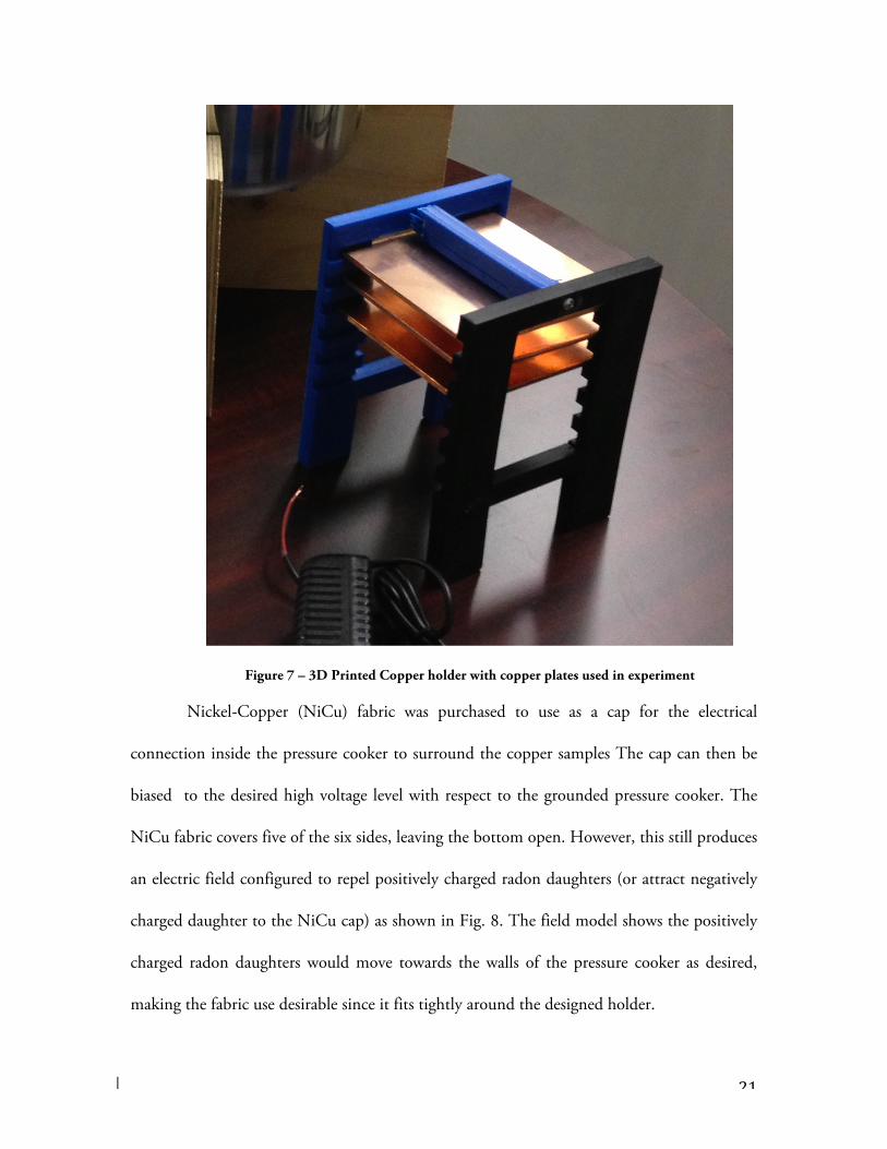
wide copper holder allowed for this fit. The 3D-printed copper holder is shown in Figure 7.
21
Figure 7 – 3D Printed Copper holder with copper plates used in experiment
Nickel-Copper (NiCu) fabric was purchased to use as a cap for the electrical
connection inside the pressure cooker to surround the copper samples The cap can then be
biased to the desired high voltage level with respect to the grounded pressure cooker. The
NiCu fabric covers five of the six sides, leaving the bottom open. However, this still produces
an electric field configured to repel positively charged radon daughters (or attract negatively
charged daughter to the NiCu cap) as shown in Fig. 8. The field model shows the positively
charged radon daughters would move towards the walls of the pressure cooker as desired,
making the fabric use desirable since it fits tightly around the designed holder.

22
Figure 8 – Simplified model of electric field inside the pressure cooker
The NiCu fabric was sewn with common plastic fishing line to provide an insulated
bond between panels of NiCu fabric in the cap, while guaranteeing that the panels
themselves make good electrical contact with one another and represent a continuous
electrical surface. The conductivity of the cap was verified by measuring the electrical
resistance between the top and sides of the cap; all sides made good contact and we observed
very low resistance across the cap. Figure 9 shows the copper fabric fit over the 3D-printed
copper holder.
0 2 4 6 8
0
2
4
6
8

23
Figure 9 – NiCu fabric being placed over the 3D-printed copper holder
The copper holder is placed inside the pressure cooker with the NiCu fabric over it as
shown. Alligator clips with insulation are then used to make good electrical contact between
the cap and the high-voltage lead to the fabric. This setup is shown in Figure 10.
Figure 10 – Connection setup to transfer voltage from the high voltage lead to the fabric

24
A control experiment was performed prior to the electric field experiment to verify
exposure levels of radon within the system. The NiCu cap was used in the control
experiment in case it had some independent effect on preventing radon plate-out even with
the field off. For each test, a five-day exposure was used to reach appropriate levels of
measurable radon. The system was setup exactly as with the proposed electric filed on
experiment to ensure the only variable was the application of the field.
Initial tests of the setup with a variable direct-current high-voltage poser supply
(HVPS) suggested that arcing would occur between the corners of the cap and the pressure
cooker walls at about 6-8 kV. This set the maximum voltage we could hope to use with the
configuration Even without arcing, we detected some corona effects that resulted in
production of ozone. Concerned with the health implications of producing ozone in a
laboratory environment, the first operation of the electric shield was conducted in a fume
hood in the SMU chemistry student laboratories. The HVPS was purchased from
Information Unlimited due to its ability to produce up to 35 kV and its relatively
inexpensive cost.. The initial setup is shown in Figure 11.

25
Figure 11 – High Voltage test setup in fume-hood with power supply shown
A confirmation experiment was done with the same voltage applied as first field-on, 6
kV. Different researchers rotated duties to ensure no results were caused by researcher-
specific handling issues the equipment or the copper plates after the exposure.

26
6 XIA UltraLo 1800
Contamination levels were inferred be measuring alpha particles from the 220Rn decay chain
using the XIA Ultra-Lo 1800 instrument. This instrument is a specialized ionization counter
comprising an active volume filled with argon, a lower grounded electrode that is a
conductive tray holding the sample and an upper pair of positively charged electrodes, shown
in Fig. 12. Of these two electrodes, the anode sits directly above the sample, while the guard
electrode surrounds and encloses the anode. Both electrodes are connected to charge-
integrating preamplifiers whose output signals are digitized and then processed by a digital
pulse shape analyzer. The inherent background in the counting chamber of the XIA is 0.001
alphas/(cm2 h).
Figure 12 – XIA UltraLo 1800 Schematic
Figure 13 shows a typical view of the analysis and operations software used by the
XIA, Counter Measure. This software is used to show the fingerprint of energies left by alpha

27
particle emission of decaying isotopes, and allows us to see the amount of each isotope
present within the copper samples. With the amount of alphas and the emissivity of the
samples assessed out in real time, analysis can be done to verify expected levels of energy
produced by the proper decay chain. These results are used to track levels of radon within the
system, and can show any reduction of radon plate-out onto the copper surfaces.
Figure 13 – CounterMeasure software from the XIA UltraLo 1800

28
7 Results
The results display an extremely promising reduction in background levels. We observe a
reduction in 98.1% of radon levels plating-out on copper shown in Table 1.
Table 1 – Results from the control and experiment
Experiment Emissivity
40 h after exposure
(alphas/(cm2*h))
E-Shield/Field Off 15.9 +/- 0.2
E-Shield/Field On 0.45 +/- 0.04
Even though the experiment only ran with one-tenth of the desired electric field, the results
showed significant levels of reduction in the background in the experiment. The
confirmation experiment showed an even better reduction, roughly by a factor of 2. While
an improvement over the original field-on exposure trial, these results are statistically
inconsistent despite attempting to hold conditions constant. This inconsistency is discussed
in the next section. Figure 12 shows a plot of the emissivity as a function of time for the
three experiments performed in this study. The electric field control and experiment are
shown on the graph as labeled.
This set of experiments demonstrated a clear and quantifiable reduction in radon
plate-out on copper using a specific, large electric potential.

29
Figure 14 – Results for the control experim
ent, initial electric field experiment, and the
confirmation experim
ent

30
8 Conclusions
The goal of this experiment was to quantify the effect that strong electric fields might have
on reducing the plate-out of radon progeny on materials. We determined through some
simple calculations that, in the worst-case scenario, a stopping potential of 60kV was
required to completely prevent radon progeny from reaching the target materials. We
designed an experiment to test this, isolating the effect of the electric field. Due to
experimental constraints such as arcing, we were only able to operate at 6kV and not the
maximum possible operation of 35kV that the power supply provides. Nonetheless, we
observed a 98.1% reduction in radon plate-out with the electric field powered on in the
setup.
As mentioned at the end of the last section, we ran a confirmation experiment to
access the reliability of the electric field’s ability to reduce plate-out of radon. We found a
factor of about 2 improvement over the original experiment. The exact cause of this is
unknown, and requires further study and investigation in a better-controlled environment.
First, the two field-on experiments were conducted in slightly different external
environments: one in a fume hood, the second in the normal laboratory environment. We
observed that ozone degraded the rubber seals around the electrical and plumbing ports in
the vessel in both experiments. For a future experimental design, we will replace the off-the-
shelf rubber o-rings and seals with a product known to resist reactions with ozone
degradation. For a further iteration of the experiment, we may look into alternate designs for
the E-shield setup that will isolate the stored materials from ozone.

31
Figure 15 – Schematic for potential redesign of experimental setup
Figure 15 shows a potential redesign to replace the pressure cooker for the
experimental vessel used in the E-shield experiment. The vessel is designed with the
experiment in mind, and makes use of predetermined insulated surfaces, shown in blue, and
conductive surfaces, shown in yellow. The electric field can be applied to the NiCu fabric as
previously done, but the ground can be applied to the two conductive surfaces in hopes of
attracting the radon daughters to these surfaces for counting purposes. These conductive
surfaces can be removed from the experiment so that the radon measurements before and
after the experiment can be determined for better understanding of the experiment. The
dimensions are designed to be able to use the full 35kV from the HVPS without arcing.
Tests were done to ensure that 6 inches is plenty of separation so that no arcing occurs in the
experiment throughout the exposure period.

32
Experimental setup and calculations were hugely successful in bringing together a
cohesive experiment that allows a test for the community of low background research to
better understand storage and shielding techniques for reducing radon plate-out on copper
surfaces. Future experiments will help us to further quantify exactly how exactly electric
fields contribute to repelling radon and its daughter particles away from setups. Future
projects for other undergraduate research students are already in the planning stages, starting
with the projects outlined above.
Valuable experience was gained in analyzing and properly setting up high voltage
electric fields. This information and conclusions on the ability for electric fields to repel
radon progenies will allow further investigation into what has been decades of research in this
field. The author is grateful for all those that have helped him in his course of study and
those who will continue into the investigations as to how to improve low radioactive studies
using electric fields to reduce background.
33
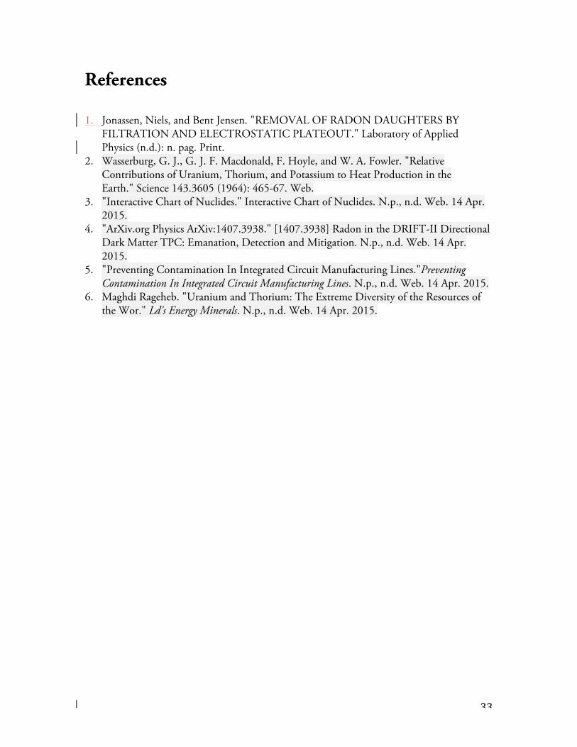
References
1. Jonassen, Niels, and Bent Jensen. "REMOVAL OF RADON DAUGHTERS BY FILTRATION AND ELECTROSTATIC PLATEOUT." Laboratory of Applied Physics (n.d.): n. pag. Print.
2. Wasserburg, G. J., G. J. F. Macdonald, F. Hoyle, and W. A. Fowler. "Relative Contributions of Uranium, Thorium, and Potassium to Heat Production in the Earth." Science 143.3605 (1964): 465-67. Web.
3. "Interactive Chart of Nuclides." Interactive Chart of Nuclides. N.p., n.d. Web. 14 Apr. 2015.
4. "ArXiv.org Physics ArXiv:1407.3938." [1407.3938] Radon in the DRIFT-II Directional Dark Matter TPC: Emanation, Detection and Mitigation. N.p., n.d. Web. 14 Apr. 2015.
5. "Preventing Contamination In Integrated Circuit Manufacturing Lines."Preventing Contamination In Integrated Circuit Manufacturing Lines. N.p., n.d. Web. 14 Apr. 2015.
6. Maghdi Rageheb. "Uranium and Thorium: The Extreme Diversity of the Resources of the Wor." Ld's Energy Minerals. N.p., n.d. Web. 14 Apr. 2015.