Studies on Hydrodynamic Propulsion of a Biomimetic...
30
24 Studies on Hydrodynamic Propulsion of a Biomimetic Tuna Afzal Suleman and Curran Crawford University of Victoria Canada 1. Introduction Current unmanned undersea vehicles (UUVs) are almost exclusively propeller driven designs, which must inherently be optimized for a particular speed, sacrificing low speed manoeuvrability for cruising efficiency. Recently, biomimetic approaches to underwater vehicle propulsion have illuminated the exciting possibilities for performance improvements made possible by emulating fish motion. In particular, a number of test vehicles indicate that the carangiform swimming mode employed by highly developed species of fish, such as the Bluefin tuna, offers both a more efficient propulsion mechanism than propellers, in addition to the ability to perform quick manoeuvring. This book chapter presents studies on the propulsion efficiency of a biomimetic tuna at the University of Victoria. Two prototypes have been designed and implemented experimentally. The first prototype consists of a biomimetic tuna that employs shape memory alloy wires to affect shape induced propulsion. The second prototype propulsion model consists of four joints that are rotated using servomotors. Issues related to the mechanism, systems and energy are discussed. The performance and the lessons learned related to the two design philosophies are presented and discussed. 2. Background and motivation Underwater vehicle design has in the past primarily focused on propeller driven designs. Research efforts have been directed towards optimizing propeller design for particular operating speeds, and also on improving manoeuvring performance through control surface, hull, and thruster configuration and design. Through computing power and mechanical system design improvements, unmanned undersea vehicles (UUVs) have been able to expand their operating envelope and carry out more ambitious, extended, and varied missions including oceanographic surveys, reconnaissance, cable laying, and mine hunting. Propeller driven designs inherently involve design tradeoffs; speed is traded for low speed manoeuvrability, and efficiency is balanced against operational speed range requirements. Natural biological evolution has also struggled with the same design considerations, and produced extremely efficient modes of propulsion over millions of years of natural selection. The emerging field of biomimetics seeks to exploit this natural design process by copying the refined forms of living creatures found in nature. In the area of hydrodynamic propulsion, highly evolved species such as the Bluefin tuna employing the carangiform Open Access Database www.intechweb.org Source: Underwater Vehicles, Book edited by: Alexander V. Inzartsev, ISBN 978-953-7619-49-7, pp. 582, December 2008, I-Tech, Vienna, Austria www.intechopen.com
Transcript of Studies on Hydrodynamic Propulsion of a Biomimetic...

24
Studies on Hydrodynamic Propulsion of a Biomimetic Tuna
Afzal Suleman and Curran Crawford University of Victoria
Canada
1. Introduction
Current unmanned undersea vehicles (UUVs) are almost exclusively propeller driven designs, which must inherently be optimized for a particular speed, sacrificing low speed manoeuvrability for cruising efficiency. Recently, biomimetic approaches to underwater vehicle propulsion have illuminated the exciting possibilities for performance improvements made possible by emulating fish motion. In particular, a number of test vehicles indicate that the carangiform swimming mode employed by highly developed species of fish, such as the Bluefin tuna, offers both a more efficient propulsion mechanism than propellers, in addition to the ability to perform quick manoeuvring. This book chapter presents studies on the propulsion efficiency of a biomimetic tuna at the University of Victoria. Two prototypes have been designed and implemented experimentally. The first prototype consists of a biomimetic tuna that employs shape memory alloy wires to affect shape induced propulsion. The second prototype propulsion model consists of four joints that are rotated using servomotors. Issues related to the mechanism, systems and energy are discussed. The performance and the lessons learned related to the two design philosophies are presented and discussed.
2. Background and motivation
Underwater vehicle design has in the past primarily focused on propeller driven designs. Research efforts have been directed towards optimizing propeller design for particular operating speeds, and also on improving manoeuvring performance through control surface, hull, and thruster configuration and design. Through computing power and mechanical system design improvements, unmanned undersea vehicles (UUVs) have been able to expand their operating envelope and carry out more ambitious, extended, and varied missions including oceanographic surveys, reconnaissance, cable laying, and mine hunting. Propeller driven designs inherently involve design tradeoffs; speed is traded for low speed manoeuvrability, and efficiency is balanced against operational speed range requirements. Natural biological evolution has also struggled with the same design considerations, and produced extremely efficient modes of propulsion over millions of years of natural selection. The emerging field of biomimetics seeks to exploit this natural design process by copying the refined forms of living creatures found in nature. In the area of hydrodynamic propulsion, highly evolved species such as the Bluefin tuna employing the carangiform O
pen
Acc
ess
Dat
abas
e w
ww
.inte
chw
eb.o
rg
Source: Underwater Vehicles, Book edited by: Alexander V. Inzartsev, ISBN 978-953-7619-49-7, pp. 582, December 2008, I-Tech, Vienna, Austria
www.intechopen.com

Underwater Vehicles
460
swimming mode have been optimized for high speed cruising, while retaining excellent manoeuvring capabilities. Previous research, including the RoboTuna (Barret, 2000), RoboPike (Kumph, 2000), and VCUUV (Anderson & Kerrebrock, 2000), has proven the potential of emulating fish swimming in underwater vehicles, and suggest exciting possibilities for performance improvement over traditional UUV design in both efficiency and manoeuvrability. A study on the swimming modes for aquatic locomotion has been published by Stafiotakis et al (1999). Chiu et al. (2000, 2002) have analyzed and simulated the undulatory locomotion of a flexible slender body. Guo et al (2002) have proposed a method for coordinating body segments for controlling the motion of a biomimetic autonomous underwater vehicle. Barret et al (1996) used genetic algorithms to determine the optimal body motion of the RoboTuna. Harper et al (1998) and Blickhan and Chen (1994) have studied several methods for measuring the power of swimming fish. Due to the complexity of the fluid dynamics problem, analytic and computational analysis of the problem has not yet progressed to the point where proper simulation of the body and caudal fin is possible. Progress has been made though, starting with inviscid flow analysis in two dimensions (Lighthill, 1970), with current research efforts focusing on full CFD simulation of the entire fish with vorticity and turbulence. Previous biomimetic fish designs have used conventional actuators, including cable drives, servomechanisms, and hydraulics. Development of multifunctional materials such as piezoelectrics, magnetostrictive materials, and shape memory alloys (SMAs) has presented an alternative actuation method. For this particular application, shape memory alloys are the most suitable of the multifunctional materials since they offer both the necessary strains and forces required for underwater propulsion. Piezoelectrics may also find applications in such a vehicle for small shape changes in the fins or selective stiffening of the actuated structure. However, SMAs have a number of potential advantages, including simplicity, noiseless operation, and low driving voltages. They can be used as direct linear actuators, and do not require gearing systems, reducing system complexity and making them ideal for confined space applications. Since they are essentially solid-state electrical devices, they produce no acoustic signature, a valuable asset for some missions such as covert military operations and for sensitive acoustic measurements. The low driving voltages required are also suited to power supplies typically available on UUVs. SMAs do have a number of drawbacks however, including low energy efficiency and performance degradation under repetitive operation beyond a couple of million cycles. The design of the SMA fish is such that new smart actuators could be easily integrated as they become available, in order to overcome some of these disadvantages. The “undulatory vehicle,” has utilized SMAs for propulsion, however it was based on the hydrodynamically inefficient eel (Wardle & Reid, 1997). SMA actuators have also been successfully used for an actively controlled hydrofoil (Rediniotis, 1999). The objective of this research is to develop a more efficient method of driving underwater vehicles using shape induced propulsion. The replacement of propellers with fish like locomotion is expected theoretically to offer 15-20% improvements in efficiency. Fish like propulsion should offer more stealthy designs of vehicles. The following strategies for shape induced propulsion have been considered: (i) in the first instance, prototype I using SMA wires to induce shape control of the tuna body was concetpualized, manufactured and tested. These SMA devices act like little muscles. When they are heated they contract and when cooled they expand. A fish was designed using SMA wires as muscles to produce the
www.intechopen.com

Studies on Hydrodynamic Propulsion of a Biomimetic Tuna
461
swimming action. This research resulted in some insightful observations based on the quantitative and qualitative results. The fish mechanism created measureable thrust while requiring large amounts of power for its operation. This finding suggested that a new approach was needed. The power requirement alone would mean that the fish would require a large battery source; (ii) next, the prototype II ServoTuna design was introduced to overcome these problems. This prototype was controlled by a single chip microcontroller which executed swimming motions using its four servomotors by autonomous control. The “travelling wave” type motion that is peculiar to fish was programmed into the single chip computer and it executed the correct wave pattern. The results obtained using the second generation prototype were more promising.
3. The shape memory alloy induced propulsion: prototype I
3.1 Design considerations The design constraints initially placed on the vehicle included a 1m total length with 50% actuated length, typical of the biological carangiform swimming mode and previous biomimetic projects. In addition, some form of actuated surface for pitch and roll control was included, and provision for mounting a mast for tow tank testing was included. In order to preserve the biomimetic approach to the design of the SMA fish and in the absence of detailed results from computational hull form optimisation, the profile of a real Bluefin tuna was used for the side profile. The Bluefin tuna was selected for its highly evolved cruising speed efficiency, and its carangiform swimming mode that in nature involves actuating approximately 50% of the fish’s length. Two physical features of the tuna are though to contribute to its efficiency in addition to the swimming mode: the “necking” of the profile at the caudal peduncle, and the high aspect ratio caudal fin. The top profile followed extremely closely the shape of modern low drag airfoils, and consequently a NACA 63-015A airfoil section was chosen for this profile. The cross section of the entire hull is elliptical, again emulating nature. This cross section was chosen to reduce the bending stiffness of the hull in the posterior actuated segment, and also to provide the optimum hydrodynamic shape for the actuated segment while still retaining internal volume in the pressure hull. Patching a circular cross section forward to an aft elliptical cross section may be an option for future deep-diving designs, but would almost certainly compromise efficiency. Examination of the biological tuna reveals that all of the fins except for the caudal fin fold into the body at cruising speed. For this reason, all of the fins except for the caudal and pectoral fins were excluded. The pectoral fins are essentially canards as they are located forward of the centre of mass, and will be used for both roll and pitch control, with modulation of the tail motion to be used for yaw control. For propulsion efficiency studies, these were not considered. Figure 1 illustrates the general layout of the SMA fish Prototype I. Since the forward 50% of the body is non-actuated, it was constructed as a rigid shell and contains controllers, sensors, and a power source. For design simplicity, the nose cone is designed as a pressure hull in order to easily include on-board power and control later in the development cycle. The nose cone was constructed as a moulded fibreglass shell, with an aluminium bulkhead at the aft end, which mates to another bulkhead to which the actuated segment is attached. The two bulkheads were sealed together by means of an O-ring, allowing for easy access to the interior of the nose cone. The nose cone was reinforced
www.intechopen.com

Underwater Vehicles
462
by aluminium ribs that would also include a hard point for mounting to the towing tank mast. In addition, the sealed pivots for the canards were located in the nose cone and attached to the ribs, along with the servos to control them. Any control electronics, internal ballast, and eventually batteries would also be attached to the ribs. This design has been successfully used in all of the other fish projects reported in the literature.
Fig. 1. The shape memory alloy based design
3.2 The actuated tail section This section of the hull occupies the aft portion of the hull, and accounts for the other 50% of the hull, including the caudal fin. The caudal fin contributes the bulk of the propulsive force in the carangiform swimming mode that is being emulated, however the travelling wave that is present in the tail is also an important factor to the overall efficiency of the design, and therefore the tail was designed to be flexible. In order to achieve this, a “skeletal” structure was developed over which “skin” is stretched. The basic element of the skeleton is a spline element running from the bulkhead aft to the tail peduncle. This spline provides a smooth curving shape to the tail along its length. Ribs (again with elliptical cross section) were then attached to the spline to provide the 3-D form of tail. The entire tail section was flooded in order to avoid the complicated problem of sealing it, especially for deep diving missions. Flooding of the tail will also drastically increase the cycle frequency possible with the SMAs due to the increased heat convection off of the wires during cooling in water however at a higher energy cost. A number of rib designs have been used in the past. Most are a variation on complete cross sections built out of aluminium (RoboTuna), plastic (undulatory vehicle), or foam (Draper Tuna), bolted to the spline. An interesting approach to the rib design problem was used on the RoboPike project; the ribs were formed out of fibreglass as a continuous helical spring, bolted along its length to the spline. In order to simplify the rib production and assembly process, the SMA fish uses “half-ribs” formed out of fibreglass. Since the ribs are formed in two halves, a single half mold was used to form the ribs for both sides of the fish. Mounting of the ribs on the spline was also simplified, since the ribs were simply bolted together through the spline without the need for bonding mounting blocks to the ribs or other complicated schemes. The ribs were placed approximately every 2.54 cm, and have a width of approximately 1 cm.
www.intechopen.com

Studies on Hydrodynamic Propulsion of a Biomimetic Tuna
463
The skin material for the tail must allow the tail to flex while at the same time avoid deflections in the unsupported regions between ribs. The skin must also be impermeable so that fluid is forced to move along with the surface of the tail and thereby provide some of the thrust. Previous designs have all used Lycra as the skin material over a layer of reticulated foam or steel mesh avoid the problem of bulging between the ribs. The Lycra is by its nature impervious to water (there are also some surface treatments of the fabric available to reduce the permeability further) and has a very low elastic modulus. The layer of foam essentially forms a composite plate structure by increasing the bending stiffness of the fabric while not adversely increasing the tensile modulus that must be low to allow bending of the overall tail. Neoprene (wetsuit material) combines these functions, since it is actually comprised of a core of foam covered on both sides by Lycra fabric. It is available in thicknesses down to 1.5 mm, the same thickness used on modern high performance full body swimsuits that allow for a free range of motion of the swimmer. By aligning the fibres
of the Lycra at 45° to the lateral axis of the fish the tensile modulus of the skin is minimized while retaining the bending stiffness of the fabric. The skin was hemmed at the forward end and the elasticity of the material holds it in a groove in the nose cone. At the tail end, the material wraps around the end of the caudal fin with a Velcro strip to hold it in place. There are two possible approaches to actuating the tail section using SMAs. In the robotic based design, it seeks to adapt SMA actuators to the designs that have been used in past projects that construct the tail as a robotic linkage. In these designs, the actuators effect rotation of the links, and the motion of the tail links is transmitted in some manner to the spline. In the RoboTuna, the tail has 6 actively controlled degrees of freedom, while in the VCUUV there are four. In these designs, as the links rotate with respect to one and other, the spline must extend. This is accomplished in the RoboTuna by means of a segmented spline, while in the case of the VCUUV follower rods mechanisms are used to transfer the motion of the links to the spline. Adapting this approach to the SMA fish, the concept shown in Figure 2 was developed with four wires per side of the joint. There are four controlled joints in this design, all with SMAs mounted in the “lever” configuration. This design allows the actuating wire to strain the wire on the opposing side, in order to set-up for the next cycle. In this way, the one-way shape memory effect can be used with no need for an external force to re-strain the wires after each cycle. The SMAs are secured to the links by Plexiglas clamp blocks at one end, and individually clamped with a bolt and washers at the other end to allow for adjust of tension in the each wire, as illustrated in Figure 2. Initially, the links themselves were made of aluminium, with two ball bearings at each pivot point. The axles for the ball bearings also served as the shafts about which the spline blocks pivot, and were secured in the links with setscrews. Two e-clips along each pivot shaft retained the bearing and locate each spline block assembly. These blocks allowed the spline to extend during operation, and must themselves pivot about the same axes as the links to ensure smooth curvature of the spline. They were made of Delrin with stainless steel for the slider rods. One end of each of the slider rods has an e-clip positioned so that the extension of the spline is limited to avoid excessive local curvature of the spline segment. The opposite end of the rod is screwed into the other block. The spline is simply bolted to the spline blocks, and located in the groove in the blocks. The tail linkage and root spline segments are all bolted to the aft bulkhead. It was found that this approach was suited to conventional actuation methods such as cables and hydraulics, but somewhat defeats the purpose of utilizing SMAs to reduce the complexity of the vehicle.
www.intechopen.com

Underwater Vehicles
464
Fig. 2. The actuated tail section design
In an effort to adopt a more adaptive structures approach to the SMA fish, a new tail section was designed to take advantage of the SMA characteristics. In this design, the spline itself is actuated, much like the undulatory vehicle. The skeletal links are retained in this design, but their function changes to preventing torsion of the caudal fin about the lateral axis of the fish. In the absence of tail linkages, differential shedding of vortices off of the two tips of the fin would lead to a torsional moment on the spline, causing a change in the angle of attack of fin. This would lead to uncontrollable coupled pitching and yawing. It may be possible in future design to eliminate the need for tail linkages by using the torsional strength of the
skin (note that the 45° orientation of the Lycra fibres increases the effective torsional stiffness of the tail) in conjunction with actuators at 45° to the lateral axis on the spline itself to control the torsion of the spline. For the present prototype, the inclusion of the tail linkages greatly simplifies initial testing by eliminating torsional deformation from unbalanced forces on the tail, while not contributing undue complexity to the design. The links must contract in order for the spline to freely flex. This is accomplished in much the same manner as the spline sliders in the robotic design, using slider rods with the extent of travel limited by e-clips. The larger block is made of Delrin through which the rods will slide, while the other spine blocks are of aluminum. The rods thread into these blocks, and bearings are also located in the blocks, two per pivot axis. The aft spine linkage assembly is somewhat more complicated, since at the forward end it must be able to contract, and at the aft end be rigid for the set of SMAs controlling the caudal peduncle pivot. Note that this design again allows for three regions of the spline to be controlled, as well as the peduncle for a total of 4 DOF. The caudal fin was made in same manner as the canards with epoxy covered wood, laminated on a Plexiglas block at the peduncle pivot. The spline is again attached to the links at the same pivot points as the links themselves by means of Delrin blocks that themselves pivot about the same axes as the links. The same blocks provide mounting points for the SMAs, clamped at the aft end between aluminium spacers and at the forward end by bolts and washers. The aluminium spacers are contained within grooves in the Delrin blocks and clamped with two bolts visible at the end of each spline block. The mounting of the SMAs for the caudal peduncle section is the same as outlined earlier. The cutouts in the spline serve to reduce its bending stiffness while
www.intechopen.com

Studies on Hydrodynamic Propulsion of a Biomimetic Tuna
465
preserving the structural integrity for supporting the ribs. The spline was made of 0.8 mm Delrin sheet. The completed tail section prototype is shown in Figure 3.
Fig. 3. The tail section prototype
4. SMA actuators
The shape memory effect is exhibited by a number of alloys, however the most common one is an alloy of Ni-Ti, referred to as Nitinol. The one-way shape memory effect occurs after an external force strains the material in its cold state. Upon heating, the material will return to the initial “remembered” shape, and if the material is constrained can produce a considerable force on the constraints. This effect is explained from a crystal structure approach by the following; the low temperature phase is martensite and possesses a low yield strength, which is easily plastically deformed by and external force. Upon heating past the transition temperature of the alloy, the phase of the material changes to austentite, a phase with high elastic modulus and yield strength, and due to the training process will attempt to return to the remembered shape. The transition temperature can be tailored by
the alloying and heat treatment process to obtain a value between –100°C and 100°C. Nitinol can be obtained in a variety of forms, including thin film, rod and bar, tube, and wire stock. It is usually sold in its as formed state, and must undergo a complex heat treatment process in order to “train” it and thereby attain its memory. The process consists of heating and coiling cycles over which the material is strained from its remembered state, and must be repeated over 50 times. Nitinol has been made available by Mondo-Tronics in pre-trained wire form, making
integration into various robotics projects quite strait forward. The commercial name is either
“Muscle Wires” or “Flexinol.” The wires are available in a number of diameters ranging
from 37μm up to 0.375mm, and are actuated by passing a current directly through the
length of the wire. Larger wires can exert higher forces, however require correspondingly
higher currents for Joule heating and are not capable of fast cycling. Low and high
temperature wires are available with transition temperatures of 70°C and 90°C respectively,
and care must be taken to avoid overheating which destroys the wires. The low temperature
www.intechopen.com
Underwater Vehicles
466
wires were considered here due to the fact that they will be immersed in water that ensure
adequate heat transfer for cooling. (Note that operating the wires in water is advertised to
permit over 10 times the frequency of operation compared to operation in air due to
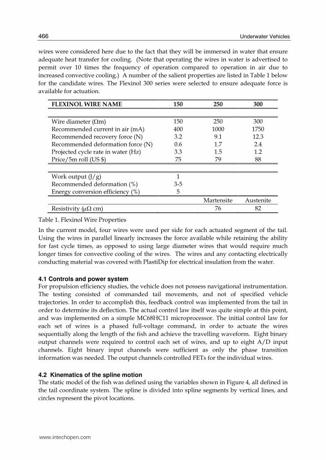
increased convective cooling.) A number of the salient properties are listed in Table 1 below
for the candidate wires. The Flexinol 300 series were selected to ensure adequate force is
available for actuation.
FLEXINOL WIRE NAME 150 250 300
Wire diameter (Ωm) 150 250 300 Recommended current in air (mA) 400 1000 1750 Recommended recovery force (N) 3.2 9.1 12.3 Recommended deformation force (N) 0.6 1.7 2.4 Projected cycle rate in water (Hz) 3.3 1.5 1.2 Price/5m roll (US $) 75 79 88
Work output (J/g) 1 Recommended deformation (%) 3-5 Energy conversion efficiency (%) 5
Martensite Austenite
Resistivity (μΩ cm) 76 82
Table 1. Flexinol Wire Properties
In the current model, four wires were used per side for each actuated segment of the tail.
Using the wires in parallel linearly increases the force available while retaining the ability
for fast cycle times, as opposed to using large diameter wires that would require much
longer times for convective cooling of the wires. The wires and any contacting electrically
conducting material was covered with PlastiDip for electrical insulation from the water.
4.1 Controls and power system For propulsion efficiency studies, the vehicle does not possess navigational instrumentation.
The testing consisted of commanded tail movements, and not of specified vehicle
trajectories. In order to accomplish this, feedback control was implemented from the tail in
order to determine its deflection. The actual control law itself was quite simple at this point,
and was implemented on a simple MC68HC11 microprocessor. The initial control law for
each set of wires is a phased full-voltage command, in order to actuate the wires
sequentially along the length of the fish and achieve the travelling waveform. Eight binary
output channels were required to control each set of wires, and up to eight A/D input
channels. Eight binary input channels were sufficient as only the phase transition
information was needed. The output channels controlled FETs for the individual wires.
4.2 Kinematics of the spline motion The static model of the fish was defined using the variables shown in Figure 4, all defined in
the tail coordinate system. The spline is divided into spline segments by vertical lines, and
circles represent the pivot locations.
www.intechopen.com

Studies on Hydrodynamic Propulsion of a Biomimetic Tuna
467
x = 0
xS1 xS2 xS3 xS4 xS5 xS6
xP1 xP2 xP3 xP4 xP5 = xCP
xS7
s1 s2 l1 s3 s4 l2 s5 s6 s7 l4 l3
Half-Length of Fish Tip of Caudal Fin
Centerline of Fish
Fig. 4. Relevant coordinates of the tail
The deformed locations of the endpoints of the splines are labelled (xi,yi) and the deformed pivot locations (xpi,ypi) as illustrated in Figures 5 and 6.
(xS1,0)
(x1,y1)
(xp2,yp2)
(x2,y2) θ1
Spline Segment 1
(x2,y2)
(x3,y3)
(xp3,yp3)
(x4,y4) θ2
Spline Segment 2
(x4,y4)
(x5,y5)
(x4,y4) θ3
Spline Segment 3
Fig. 5. Deformed spline coordinates
(x6,y6)
θ4
(xp5,yp5)
Caudal Peduncle
Caudal Fin Tip
Caudal Fin
(xp5,yp5)
θ5
(xp3,yp3)
(xp4,yp4)
Caudal Peduncle Placement on Vertebra 4
Fig. 6. Deformed Caudal Fin Coordinates
In order to determine a physically realistic pivot location, the length of the splines must be maintained, assuming there is no in-plane straining. The arc-length formula is used for this:
∫ ⎟⎠⎞⎜⎝
⎛+= i
s
x
x
s dxdx
dyl
2
1
(1)
where xs is the coordinate of the starting point of the spline, xi is the endpoint of the spline in question and y is the defining function of the spline in question. The slope of the travelling wave is also needed, as follows:
TW'x( )= 2A
0x sin ωt − kx( )− A
0k x
2cos ωt − kx( ) (2)
www.intechopen.com

Underwater Vehicles
468
Matlab was used to solve the necessary equations, using the built in spline functions. The algorithm implemented was to minimize:
( ))('tan 1
xTWi−−=Δ θ
(3)
where θi is the end slope of the spline in question and the design variable for the optimisation problem. For each unique value of θi, there is a unique solution to the placement of the pivot point, since the end slope thereby defined; this was implemented in
Matlab by searching for the zero of si ll −=δ where li is undeformed length of the spline in
question and ls is as defined in equation 1. For this optimisation problem, xpi is the design variable. Once the spline endpoints are determined, the location of the caudal peduncle (xp5,yp5) is determined from geometry, followed by the location of the tip of the caudal fin (xp6,yp6), using:
( ) ( ))( 66
256
256
24
xTWy
ypyxpxl
=−+−=
(4)
4.3 SMA strains Once the endpoints of the rigid Delrin blocks are determined (same as the locations of the
endpoints of the splines), the dynamics locations of the ends of the SMA wires can be
determined from simple geometry. The actual length l of the wires at all time steps is easily
determined (from a knowledge of the location and orientation of the Delrin blocks), and
compared to the undeformed length of the wire L. When the tail is straight, there is a pre-
strain εp in each wire at length L’. Eq. (5) therefore describes the instantaneous strain in the
wire and it is independent of L since there is no way to calculate it from the tail parameters,
whereas L’ can be computed from the geometry of the tail:
( )'
'1
L
Ll p −+= εε
(5)
The 3-D model of the fish was created in Matlab using surfaces defined by X, Y, and Z matrices. The x-axis is along the length of the fish with the origin at the nose, y is the horizontal plane and z in the vertical. The profiles of the fish body are defined by the same coordinates used in the CAD model of a real tuna and NACA airfoil, and the caudal fin has a simple airfoil cross-section. The cross-sections of the body are ellipses defined by:
)(
)(
2..0
)sin(
)cos(
Pr_
Pr_
xFb
xFa
bz
ay
ofileAirfoil
ofileTuna
=====
πααα
(6)
The sections on the tail and nose cone are equally spaced, and the cross-sections for the tail are defined by the rib locations. Using the time history of the spline, the position and
www.intechopen.com

Studies on Hydrodynamic Propulsion of a Biomimetic Tuna
469
orientation of each rib section and the tail can be determined. Transformation matrices are computed for each section of the moving tail and fin, pre-multiplied together, and then multiplied with the respective coordinates of the cross-sections.
Fig. 7. The tail components superimposed on the travelling wave
Fig. 8. The time step visualization of the tail motion
There are three main outputs of the spline motion and strain calculations, which can be run for various percentages of the tail period: a superimposed image of the tail position on the
www.intechopen.com
Underwater Vehicles
470
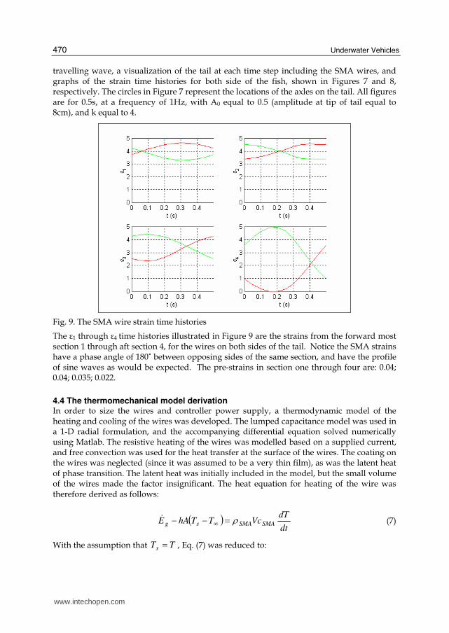
travelling wave, a visualization of the tail at each time step including the SMA wires, and graphs of the strain time histories for both side of the fish, shown in Figures 7 and 8, respectively. The circles in Figure 7 represent the locations of the axles on the tail. All figures are for 0.5s, at a frequency of 1Hz, with A0 equal to 0.5 (amplitude at tip of tail equal to 8cm), and k equal to 4.
Fig. 9. The SMA wire strain time histories
The ε1 through ε4 time histories illustrated in Figure 9 are the strains from the forward most section 1 through aft section 4, for the wires on both sides of the tail. Notice the SMA strains have a phase angle of 180˚ between opposing sides of the same section, and have the profile of sine waves as would be expected. The pre-strains in section one through four are: 0.04; 0.04; 0.035; 0.022.
4.4 The thermomechanical model derivation In order to size the wires and controller power supply, a thermodynamic model of the heating and cooling of the wires was developed. The lumped capacitance model was used in a 1-D radial formulation, and the accompanying differential equation solved numerically using Matlab. The resistive heating of the wires was modelled based on a supplied current, and free convection was used for the heat transfer at the surface of the wires. The coating on the wires was neglected (since it was assumed to be a very thin film), as was the latent heat of phase transition. The latent heat was initially included in the model, but the small volume of the wires made the factor insignificant. The heat equation for heating of the wire was therefore derived as follows:
( )
dt
dTVcTThAE SMASMAsg ρ=−− ∞$
(7)
With the assumption that TTs = , Eq. (7) was reduced to:
www.intechopen.com

Studies on Hydrodynamic Propulsion of a Biomimetic Tuna
471
( )( )SMASMA
e
SMASMAe
cD
TTDhl
RI
dt
dT
dt
dTc
DTTDh
l
RI
2
2
22
4
4
πρπ
πρπ∞
∞
−−=⇒
=−−
(8)
In order to calculate the free convective coefficient h , the Nusselt number was calculated as
follows (Incorpera and DeWitt, 1975):
2
278
169
61
Pr
559.01
387.06.0
⎪⎪⎪⎪⎭
⎪⎪⎪⎪⎬
⎫
⎪⎪⎪⎪⎩
⎪⎪⎪⎪⎨
⎧
⎥⎥⎦⎤
⎢⎢⎣⎡ ⎟⎠
⎞⎜⎝⎛+
+== DD
Ra
k
DhNu
(9)
with
( )να
β 3DTTg
Ras
D∞−=
(10)
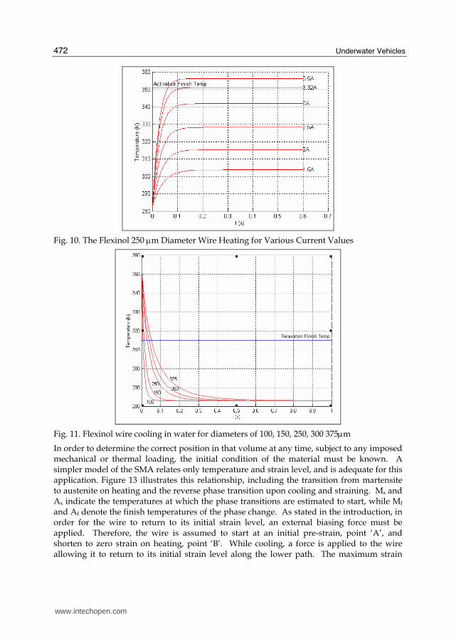
During cooling the internal heat generation term was dropped. The material properties of the SMAs were taken from the product literature for the low temperature wires, and the properties of water and air were implemented in a look-up table for increased accuracy, taken from White (1999). Performance in air for a variety of wire diameters was first examined to verify the model in relation to the published performance data. While the cooling simulation was quite accurate, the heating simulation required less current than published to attain the required transition temperatures in the wires. The simulation was then repeated using the properties of water, where the high heat transfer coefficients were found to greatly increase the required current when heating, and drastically reduce the cooling times, as reported in the product specifications. Figures 10 and 11 show the simulation results for heating and cooling respectively, along with the finish temperatures for the phase transitions. The numbers in 0
indicate the wire diameter in μm, and both results used an ambient temperature of 10˚C. The results for heating and cooling in water agree with both the product literature and experimentation with a number of test specimens.
Based on this data, the 250μm low temperature wires were chosen for the prototype, and the power supply was sized to deliver up to 3A per wire, since not all wires would be actuated simultaneously. Since no feedback mechanism was designed into the prototype, an accurate simulation of the mechanical behaviour of the wires was essential. The thermomechanical behaviour of SMAs is only just being to be carefully studied and quantified. The literature commonly refers to a dual kriging model to describe the behaviour of SMAs, relating temperature, strain, and applied stress on a three-dimensional surface, shown in Figure 12.
www.intechopen.com
Underwater Vehicles
472
Fig. 10. The Flexinol 250 μm Diameter Wire Heating for Various Current Values
Fig. 11. Flexinol wire cooling in water for diameters of 100, 150, 250, 300 375μm
In order to determine the correct position in that volume at any time, subject to any imposed mechanical or thermal loading, the initial condition of the material must be known. A simpler model of the SMA relates only temperature and strain level, and is adequate for this application. Figure 13 illustrates this relationship, including the transition from martensite to austenite on heating and the reverse phase transition upon cooling and straining. Ms and As indicate the temperatures at which the phase transitions are estimated to start, while Mf and Af denote the finish temperatures of the phase change. As stated in the introduction, in order for the wire to return to its initial strain level, an external biasing force must be applied. Therefore, the wire is assumed to start at an initial pre-strain, point ‘A’, and shorten to zero strain on heating, point ‘B’. While cooling, a force is applied to the wire allowing it to return to its initial strain level along the lower path. The maximum strain
www.intechopen.com

Studies on Hydrodynamic Propulsion of a Biomimetic Tuna
473
level must be kept below 5% in order to ensure the longevity of the wire. On the fish prototype, the wires are strained back to their initial level by a combination of the set of wires on the opposing side and the spline’s bending stress.
Fig. 12. Heating thermal cycles corresponding to an initial content of 40, 70 and 100% of martensite: the hysteretic volume is created using the sampling sets obtained for loads of 53, 107 and 160 MPa (Volkov, Trochu and Brailosvski, 1999).
Str
ain
Lev
el (
Incr
easi
ng
)
Temperature (Increasing)
As Af Mf Ms
Heat an
d C
on
tract
Co
ol an
d R
elax
A
B
0
Fig. 13. Graph of Strain Level Versus Temperature for SMA
In order to implement a thermo mechanical model, only the transition from martensite to austenite was considered, and assumed to be linear according to Eq. (11). The reverse transformation could be formulated in an analogous manner.
f
i
fsA
AAT +−= εε
(11)
where εi is the strain in the wire at the start of the transition. Notice that this equation defines the required temperature of the wire based on the required strain.
5. Controller design
The length of the wires and corresponding resistances allowed a 5V source to be used to drive enough current through the wires for the anticipated heating requirement. A pulse width modulation scheme was used to control the voltage applied to the wire and the
www.intechopen.com

Underwater Vehicles
474
temperature of the wire, with a 5V maximum. Using the strain time histories from the structural simulations run at 1Hz (tail beat frequency) as the input to the control law, a method was derived to compute the control files used by the ACE controller to move the tail. The update frequency of the control law was nominally set at 20 Hz, so 20 commands were needed over a 1 second time interval. To avoid damaging the wires, the wires on opposite sides of the tail are never actuated simultaneously. Consequently, the commands were computed for the time periods of decreasing strain. The strain during these time intervals was converted to a commanded temperature using Eq. (11). As an adequate approximation and to avoid complicated analysis, those temperatures were then converted to voltages using the required voltage at steady state conditions. While not strictly true, the solution of the differential heat equation for the controller was not warranted at this stage of development, and so the following equation was derived for the steady state temperature by dropping the transient term.
( )( )∞
∞
−=⇒
−=
TTRlD
V
TThAlR
V
4
2
2
π
(12)
The actual entries in the control file were then determine by the following equation:
PWM = V
5Max _ PWM _Unit _Count( ) (13)
6. Mast drag prediction
In order to simplify the construction of the tow tank apparatus, the drag of the mast was not isolated from the load cells. Consequently, the drag of the mast must be known in order to determine to thrust of the fish. This value can be estimated both experimentally in the tow tank and by testing of the mast in isolation. Experimental testing introduces other effects, however, such as the vortices shed off the tip of the mast. For this reason, an analytic prediction was sought, using a potential flow panel method combined with boundary layer estimation. The program DesignFoil (www.designfoil.com) implements a panel method for 2-D thick airfoils combined with boundary layer analysis based on the theory of T. von Kármán and K. Pohlhausen. It also provides a good user interface for airfoil coordinate definition, and outputs coefficients of lift, drag, and pitching moment, given the coordinates of the airfoil and the Reynolds number. The coordinates of the mast were measured, and then fed into the program, interpolated at 200 points on the top and bottom of the section. It was found that the results from the program converged to a steady solution when more than 300 total points were used to define the airfoil. The results of this analysis are shown in Figure 14, with the following constants used for the mast and water:
l = 2.25” (mast chord length), s = 0.56m (submerged length of mast), ⎟⎠⎞⎜⎝
⎛= lsVcF dD2
2
1 ρ
ρ = 1000 kg/m3 , ν = 1.3x10⁻⁶ m2/s @ 10°C.
www.intechopen.com

Studies on Hydrodynamic Propulsion of a Biomimetic Tuna
475
Fig. 14. Predicted mast drag as a function of velocity
7. Prototype I: thrust experiments
The proposed design and the preliminary calculations proved to fulfil the function
extremely well, with a minimum of resistance to movement. The SMA actuators have also
proven themselves capable of generating a wide range of motion in the tail. Moreover, the
controller and circuit design proved effective in providing fine motion control of the SMAs.
The structural simulations have demonstrated the ability of the tail to move according the
prescribed travelling wave motion, and provided the needed input for the design of the
control law. The thermodynamic model derived and implemented appears to agree well
with experimental results. Combined with a simple thermomechanical model of the SMA
wires, controller files were generated for motion of the tail underwater to be used in the
testing regime.
Next, the prototype vehicle was manufactured. Figure 15 shows the prototype in motion in
the test tank. Swimming motion was achieved and initial thrust measurements were taken.
The complicated heat transfer conditions made smooth activation of the SMA wires difficult.
The actuator force was also somewhat binary in nature, as the material passed through the
transition temperature. This resulted in an uneven “jerky” motion, especially when tested in
air. The damping effects of the water and skin lessened these effects, but the motion was not
perfectly fluid from port to starboard.
Fig. 15. Prototype Testing in the tank
The speed at which SMA wires can operate as actuators is limited by the rates at which they
can be heated and cooled. A further constraint is the software used for the control program,
www.intechopen.com

Underwater Vehicles
476
which has a limited cycle frequency which affects the rate of pulse-wide-modulation (PWM)
that can be achieved. Both of these constraints limited the maximum tail beat frequency to
0.5 Hz. Even at this low frequency, the power requirements were measurable.
The current sent to each wire was measured using a digital multi-meter and is presented in
Table 2. The current required at each section was different because of the different heat
transfer conditions along the length of the tail section, but symmetric about the centreline.
Port Wires Starboard Wires
Vertebra # 1 2 3 4 1 2 3 4
Max current (A) 7.4 10 6.4 3.6 7.4 10 6.4 3.6
Table 2. Current sent to individual wires
The current sent to each wire changes during one period. For this reason it is difficult to
accurately calculate the power consumption of the prototype using the basic multi-meter
available. Since exact power consumption data was not needed, a more complicated data
acquisition system was not implemented. To calculate a rough estimate of power
consumption, the current in the two supply wires to the power supplies (instead of
individual wires) was measured. The current draw on these wires was found to be relatively
steady. Table 3 contains the maximum and minimum current in supply wire one (for
vertebrae 1 and 4) and two (for vertebrae 2 and 3). The minimum and maximum power
consumptions were calculated to be 292.8 W and 333.6 W respectively.
Current in Supply Wire 1 (Section 1and 4) Current in Supply Wire 2 (Section 2 and 3)
Max Min Max Min
15.9 A 13.8 A 11.9 A 10.6 A
Table 3. Maximum and minimum current draws in supply wires 1 and 2
In fish motion, it is of interest to know the amplitude of the wave that the tail section
follows, as well as the angle of attack of the caudal tail fin. A digital video camera was used
to capture the motion of the fish swimming. Using a 5 mm grid on the bottom of the test
tank, the amplitude of the motion and angle of attack of the caudal tail fin was observed as
shown in Figure 16.
Fig. 16. Maximum displacement and angle of attack of caudal tail fin
www.intechopen.com

Studies on Hydrodynamic Propulsion of a Biomimetic Tuna
477
Properly installing each SMA wire to the exact length was difficult because of the
attachment design. The result was that the amplitude of motion on each side was not
perfectly equal. It was predicted that the range of motion of the caudal fin of the prototype
would be 100 and the amplitude will be 0.08 m. Measurements taken from the video footage
gave the results presented in Table 4. Evidently amplitude was over-predicted and angle of
attack under-predicted in the design simulations. Note that the camera position was
stationary, creating a parallax effect due to the single focal point. This was compensated for
in the measurements of amplitude and angle of attack. From measurements taken in the
SMA wire calibration process, strain in each wire is estimated to be 5% ± 0.5%. This is the
maximum repeatable strain that the SMA can recover from. Using the load cell mounted
on the test jig, the forward thrust developed by the prototype was measured. The thrust
was found to vary over one period of wave motion, as expected. The maximum force
that the prototype generates is 1 N.
Port Starboard
Max Tail Amplitude
Max Angle of Attack
Max Tail Amplitude
Max Angle of Attack
5.6 cm 170 5cm 140
Table 4. Maximum amplitude and angle of attack of caudal tail fin
Given the power consumption during operation, the overall level of performance,
particularly the thrust developed, was not satisfactory. There are a number of contributing
factors. The first limitation due, to the SMA actuators, is the speed of operation. The
maximum operation speed of 0.5 Hz is much lower than other prototypes currently in
testing. This is also lower than typical fish non-dimensional tail beat frequencies. The
control software is currently the limiting factor on the frequency, and it is believed that an
operation speed of 1 Hz (maximum attainable using SMA) would produce much better
results.
The second limiting factor on the performance is the amplitude of motion, particularly the
displacement of the caudal tail fin. With the SMA wires operating at 5% strain, they do not
produce enough displacement for the body of the fish or the caudal tail fin. The potential
flow analysis predicted that the optimal angle of attack is 300 for maximum thrust. The
prototype was only able to produce a maximum angle of attack of 170.
Nevertheless, the emulation of the swimming mode of a Bluefin tuna for UUV propulsion
presents exciting possibilities for performance improvements over more traditional designs.
The vehicle design, using an adaptive structures approach, has been able to realize a
significant reduction in the level of complexity of the vehicle. Construction and testing of the
SMA fish prototype has highlighted the benefits and challenges inherent in this approach to
biomimetics. While the magnitude of thrust generated was not high enough, its low value
can be attributed to the control software, rather than mechanical design. Future prototypes
may utilize faster control software and a degree of freedom for the entire body to enhance
performance. In addition, a tail section using conventional mechanical servo mechanisms for
actuation is being developed to better understand the issues associated with fish motion,
www.intechopen.com

Underwater Vehicles
478
independently of unique issues associated with the adaptive structures approach of the
SMA fish.
For this first prototype, power consumption was not a major design factor. This is because
the main goal was to simply verify that forward motion was attainable. However, in a
practical application, SMA actuators require too much power to be useful. The 300 W that
the fish required would require a power source similar to a car battery for only one hour of
operation. It is not a practical approach for autonomous vehicles. Thus, a new design based
on servo-motors is presented next in order to overcome some of the limitations dicussed in
the SMA design.
8. The servo tuna: prototype II
Based on the lesson learned from the SMA based propulsion, it was observed that the shape
adaptation system needs an actuation system that is reliable, controllable, flexible and
energy efficient. It was determined that position control using servomotors are much
simpler as the degree of rotation is directly proportional to the input duty cycle. The first
servomotor-driven prototype had two joints and two servomotors. A tail (caudal) fin was
constructed with the same proportions as a Bluefin Tuna. A waterproof case was
constructed for the motors because servomotors are not meant to be operated underwater.
For ease of construction, a single watertight case was built to house both servos. The case is
a rectangular box, machined out of aluminum. There is a channel for an O-ring and tapped
holes, where a plexiglass cover was attached. Directly above the output gears of the servos
are two holes to allow the spindles to pass through. A counter bore was above both holes,
where an O-ring could create a seal between the case and the spindle. The development of
the prototype is chronicled in Figures 17-22.
The servo closest to the caudal fin controlled the rotation of the between the servos and the
caudal fin. The servo closest to the nose of the fish controlled the caudal fin by way of
linkages. Because the links were located on one side of the apparatus, mechanical
interference occurred when the tail flapped toward the opposite side. A problem arose from
the connection between the motors and the spindles. This tuna used an injection-molded
plastic piece to connect the servo to the spindle. The plastic piece was glued and press fit
over the bar, which was the spindle. This union held for the first few trials, but after
repeated use, the spindle began to rotate in the plastic piece. As a result, the joint being
rotated would not reach the same position as the servomotor, causing the flapping of the tail
to meander. A new spindle was designed. Also, the placement of the servomotors were
changed to avoid interference.
For the complete model, the prototype II ServoTuna uses four servomotors to move four
mechanical joints located on the rear half of a tuna-like body. The design of the single link
model was changed to accommodate the two additional servos, and the mechanism that
rotated the caudal fin was improved to avoid mechanical interference.
The components of the prototype II were made of aluminum. The principle of having a
waterproof case for the servomotors was retained, but each servo had its own case. Figure
21 illustrates the isolation of the servomotors that eliminated the problem of parts
interfering with each other, as no single joint could rotate more than 90˚. In order to save
time, a few parts were modified only slightly from the original servo fish. The bearings and
www.intechopen.com

Studies on Hydrodynamic Propulsion of a Biomimetic Tuna
479
journals about which the caudal fin rotated were kept and the pieces used to attach the
caudal fin to its servo were modified only slightly. They were shortened to offset the length
added by the two extra servos.
To simulate the most lifelike swimming motion, the pivot point for the caudal fin was placed as close to the start of the fin as possible. Bluefin Tuna are quite narrow near the caudal fin. In order to keep the shape of the fish as realistic as possible, the servomotor controlling the fin had to be farther back from the joint. Therefore, a linkage between the servo and the pivot point was necessary. Four ball joints were used to transfer the rotation. The ball joints accommodated changing directions of force and the difference in height between where they attached to the spindle and to the fin. The ball joints were connected with a piece of ready rod. This set-up allows the ball joints to be reused if the distance between them is changed. The other three joints were identical to each other. A bracket was screwed into the back of the preceding servo case. The bracket clamped the spindle and aligning pin. These two parts made the axis the joint will pivot around. The spindle rotated with the motor. The aligning pin slid within a Delrin bearing. The bearing was fit into a recessed circle in the bottom of the case. The purpose of the aligning pin was to oppose the moment created by the weight of the other joints. The spindles were designed to fit over the splined output shaft of the servo and transfer the
rotation to the joint bracket, outside the servo case. It was decided that the spindle should be
one solid piece rather than two pieces joined together. The spindle had to be able to pass
through the 0.65 cm hole in the case from only one direction, so the end that fit over the
motor shaft could have a larger diameter than 0.64 cm. Because the spindle would be slid in
from the interior of the case, the spindle had to be able to slide up far enough to be out of the
way when the servomotor was inserted. Once the motor was in place, the spindle could be
pushed onto the output shaft. The complete ServoTuna fish with the four servomotors is
shown in Figure 23.
The cases were boxes made of aluminum and plexiglass. The center of the aluminum had a shape resembling a spool of thread cut out of it. This recess was where the servomotor was placed. The semicircles at the four corners were to give room for the wires exiting the servo and to allow the motors to be removed easily. Around this cutout was a groove meant for a gasket, which sealed the aluminum to the plexiglass cover. Four screws fastened the cover to the aluminum case. Another hole was drilled through the top of the case. This hole served as an exit point for the servomotor wires. Three wires roughly 7.5 cm in length passed through this 0.3 cm hole and were epoxied in place to create a permanent seal. Inside the servo case, these wires connected with those on the motor. This arrangement provided a reliable seal without permanently attaching the motors to the cases. At the bottom, the bracket was connected to the aligning pin by clamping it in a circular hole. The slight gap between the two ends of the clamp forced the ends together when the screw was tightened. This type of clamp is an effective method of preventing rotation and vertical motion. Also, the aligning pin did not need additional machining, such as holes or notches and, as such, did not require any special clamps. Creating the clamp on the end of the bracket was more time consuming than simply drilling and tapping a hole into the end of the bracket, but the result was a much stronger grip. The servo cases, which protected the motors from water damage, were 5 cm square and 0.65 cm deep. Due to the complex shapes in the servo cases, they were all made using the CNC milling machine.
www.intechopen.com

Underwater Vehicles
480
Fig. 17. Single actuator model Fig. 18. Linkage Connecting Servo to Caudal Fin Joint
Fig. 19. Servo Holder and Spindles Fig. 20. Servo holder details
Fig. 21. Spindle design details Fig. 22. The four-actuator model
www.intechopen.com

Studies on Hydrodynamic Propulsion of a Biomimetic Tuna
481
Fig. 23. The Servo Tuna: Prototype II
8.1 Servo controller There were several tasks the control program had to perform. The most important function
was to move the servos in such a way as to create a traveling sine wave along the tail.
During experimentation, it was desirable to change the amplitudes of the servos
individually and be able to adjust the frequency of the motion.
The servomotors were controlled by Pulse Width Modulation (PWM). The data acquisition
cards used with LabVIEW could only support two servomotors. Therefore, to run four
servomotors the LabVIEW program would have to use two data acquisition cards. Also,
LabVIEW could not use multitasking/multithreading, which allows several processes and
functions to operate simultaneously. Multitasking/multithreading would be helpful with
controlling four servomotors. The two most viable options were a Motorola microprocessor,
the 68HC11 in particular, and a servo controller called the Phidget QuadServo.
The Phidget QuadServo is a small circuit board with plug-ins for four servomotors. It is
programmed using Visual Basic, and it plugs into the USB port on any computer. The
QuadServo is not a microprocessor because it will not run while disconnected from the
computer. This program is object oriented, and, unlike Interactive C, the programmer starts
by creating a user interface with various buttons and numerical inputs. A PIC
microcontroller was selected for the control system. The model is a PIC16f876, a 24 pin
device with PWM capability and a 10 bit A/D built in. The programmer selected is a
QuickWriter model from Digikey. The in circuit programming mode was selected so that
the robot could be programmed without disassembling it.
A schematic of the controller is shown in Figure 24. The pins from B0 to B7 are used for the
servo control. A terminal is used to view the operational menu of the single chip computer.
Optionally a palm pilot can be used as the terminal. The max232 chip simply changes the
voltage levels from +/- 9 volts on the terminal side to 0 or 5 volt logic on the microcontroller
side. A reverse biased diode is used to capture the inductive spikes generated by the motors.
www.intechopen.com

Underwater Vehicles
482
Since they are all in parallel on the power one diode will do the job. Six analog 10 bit inputs
are available for navigational control which might use sonar to detect the sides of a pool.
Fig. 24. The servo controller
8.2 The moving wave pattern The moving wave is achieved by taking the tail motor through its range of motion in a
sequential way. Each additional motor starting at the tail has its range of motion cut in half
as compared to the previous one. The sine wave passes down the fish with the tail moving
the most. The movement tapers off as distance from the tail increases. The code is written for
a commercial PIC microcontroller C compiler by Custom Computer Services. The compiler
is called PCH.
The fish was prepared for free swimming. A 4 amp hour 6 volt gel-cell type battery was
added internally. Surface swimming was effective and achieved a swimming speed of
about 0.3 meters/second. The swimming was done outdoors at Prior Lake. In the
swimming tests, the most efficient algorithm was the straight S-wave, without the
damping factor. The fish was programmed with regular turns which were achieve by
simply biasing the tail movements to the left or right. Running in the indoor tank,
swimming efficiency was compared after a number of modifications were made to the
design. The measured thrust varied betwen 0.5 - 1.0 N. During experiments, we tested the
following different designs:
• Different swimming patterns ranging from a strait S pattern to attenuated S patterns known as “travelling wave” patterns.
• Different elastic skin coverings for the tail section. • Various flexible sheets of material to connect the tail sections.
• A dive plane mechanism to provide for increased lateral stability and to provide for underwater navigation.
www.intechopen.com

Studies on Hydrodynamic Propulsion of a Biomimetic Tuna
483
8.3 Prototype II: thrust experiments The most interesting result was that the “traveling wave” pattern programmed into the
microcontroller did not perform anywhere near as well as a simple sine wave programmed
wave. When viewing the motion of the tail from above in the water the sine wave pattern,
due to the forces of the water became a traveling wave pattern. This occurred because the
servo motors at the base of the tail were not able to achieve full displacement due to the
forces of the water on the tail sections. As we looked into the displacements of each servo
we found that more movement was possible as we get closer to the tail. Finally at the tail the
servo was achieving a full displacement.
It was remarkable that the classic “traveling wave” pattern that is in all the literature on fish
locomotion may be simply a result of the resistance of the water imposing natural
limitations on the muscle movement of the fish. This simplifies the software design. This has
important implications for the design of robots. It means that it is only necessary to program
in a straight “S” or sine swimming pattern into the tail. When the fish is pushed beyond a
certain speed the tail motion will become a “traveling wave” pattern instead. When the
“traveling wave” pattern was programmed, it resulted in a poor thrust measurement.
The current design can read analog inputs. Thus it can read a sonar input (used in Polaroid
land cameras) to see how close a pool edge is. It can do other things like sense light. The
PIC16f876 chip currently used in this research project can sense 5 analog inputs in all. The
fish might change direction by 90 degrees whenever it “saw” the pool wall coming up.
That would be a good first step into auto-navigation. The sensors were tested and found to
be effective in detecting an underwater wall.
9. Lessons learned and concluding remarks
The SMA approach offered low thrust (1 N). This was caused by a limitation on speed of
recovery time (1 second). The approach by necessity requires excessive power consumption
by a factor of 100 or more. This is because large amounts of energy are required to actuate a
submerged piece of SMA wire. The power requirement was in excess of 300 watts. An
autonomous vehicle is not likely to be achievable using this approach.
The Servo approach on the other hand presented no such limitations. Power consumption
was very modest. Five watts of power was sufficient for 4 servo motors which can be
supplied by a small battery. Swimming can be easily programmed into a single chip
computer making autonomous craft possible. Sensors can be used for auto-navigation.
We have achieved autonomous operation with a single chip computer and a gel cell battery.
The thrust of this unit ranged from 0.5 N to 1.0 N.
Waterproofing is very difficult to achieve when a rotating shaft bearing is involved.
Waterproofing was achieved by combining the use of O-rings with the filling of the engine
cavity with silicone grease. There was no leakage because the water could not displace the
grease. The O-ring served only to keep the grease and water from mixing and to keep sand
out of the mechanism. This is a key process for the successful construction of underwater
robots of all types.
A very interesting result was that the “traveling wave” pattern programmed into the
microcontroller did not perform anywhere near as well as a straight sine wave programmed
wave. When viewing the motion of the tail from above in the water, the sine wave pattern,
www.intechopen.com

Underwater Vehicles
484
became a traveling wave pattern due to the forces of the water. This occurred because the
servo motors at the base of the tail were not able to achieve full displacement. As we looked
into the displacements of each servo we found that more movement was possible as we get
closer to the tail. Finally at the tail, the servo achieved a full displacement. Another
interesting conclusion is that the “traveling wave” pattern documented in all the classic
literature on fish locomotion may be simply a result of the resistance of the water imposing
limitations on the muscle movement of the fish. It is not a pattern that is created by the fish as
much as it is a pattern derived from the interaction of the fish and the water. When a “traveling
wave” pattern was programmed into the controller, the thrust performance was greatly
reduced.
The S-pattern program combined with a speed of motion changes to a “traveling wave”,
provides greater stability when the fish encounters turbulent water. The motors will travel
further when they encounter less resistance on one side of the fish, compensating for the
reduced pressure of the water. Similarly the motors will travel less when they encounter an
increase in water resistance. The result is a fish movement that is quite resistant to turbulent
waters.
This has important implications for the design of robots. It means that it is only necessary to
program in a straight “S” or sine swimming pattern into the tail. When the fish is pushed
beyond a certain speed the tail motion will become a “traveling wave” pattern instead. The
fish will be less affected by turbulent water if it operates in the over driven mode. For this
reason it is desirable to choose servo motors which will experience attenuation of their full
travel by the forces of the water at the maximum desired speed.
Full Navigational Control: Left and right navigation are easy to achieve by simply putting a left or right bias into the servo-motor nearest the body of the fish. This slants the tail left or right. In our free swimming tests this method worked very well. The dive planes should achieve diving and underwater control when combined with a buoyancy controlling mechanism. The current prototype did not have enough free space in its interior to include this type of control. Ballasting and Stability: We were able to achieve underwater stability by handing a round
lead weight from the bottom of the fish. This ensures that the center of gravity is well below
the center line of the fish. By adjusting its position forwards and backwards we can adjust
the balance of the fish so that it sits horizontally in the water from nose to tail. It is a simple
technique to compensate for the performance of the robot as internal components are added.
Predicted Cruising Distance: The battery used offer 4 Ah. The current consumption of the
fish is approximately 1.6 A. This means that we can cruise for approximately two hours
(without fully discharging and damaging the battery). The speed was about 0.3 meters/ sec.
Therefore the cruising distance was about 2 kilometers.
The following work could be achieved in a future development project: • Scale up the robot by a factor of 200-300 percent. • Use more powerful servo motors to achieve greater speeds. • Research has shown that only 3 tail servos are required. This simplifies the design in
many ways.
• Use dive planes for underwater navigation. • Sonar remote control will be added. • Add a camera for underwater viewing that can store the images for later recovery.
www.intechopen.com

Studies on Hydrodynamic Propulsion of a Biomimetic Tuna
485
10. Acknowledgments
The contributions to this research by the following undergraduate co-op students is noted:
Erin Cooney, Hugh Patterson and Dennis Otwom, and by the research engineer Ian
Soutar.
11. References
Anderson, J. M., Kerrebrock, P. A., “The Vorticity Control Unmanned Undersea
Vehicle[VCUUV]: An Autonomous Robot Tuna”, The Charles Stark Draper
Laboratory, Inc. Projects Booklet (2000)
Barrett, D., “MIT Ocean Engineering Testing Tank Biomimetics Project: RoboTuna”,
http://web.mit.edu/towtank/www/tuna/robotuna.html, (2000)
Barrett D., Grosenbaugh M., and Triantafyllou, “The Optimal Control of a Flexible Hull Robotic
Undersea Vehicle Propelled by an Oscillating Foil”, Proceedings of the IEEE
Symposium on Autonomous Underwater Technology, Monterey, CA, pp. 1-9
(1996)
Blikhan R., and Cheng J.Y., “Energy Storage by Elastic Mechanisms in the Tail of Large Swimmers
– a Re-evaluation”, J/ Theoretical Biology, Vol 168, pp. 315-321 (1994)
Chiu F.C., Wu C.P., and Guo J., “Simulation on the Undulatory Locomotion of a Flexible Slender
Body”, 1st International Symposium on Aqua Bio-Mechanisms, Hawaii, USA, pp.
185-190 (2000)
Chiu, F.C., Guo J., Chen J.G., and Lin Y.H., “Dynamic Characteristics of a
BiomimeticUnderwater Vehicle”, Proceedings of the IEEE Symposium n Underwater
Technology, Tokyo, Japan, pp. 172-177 (2002).
Guo J., Chiu F.C., Cheng S.W., and Joeng Y.J., “Motion Control and Way-point Tracking of a
Biomimetic Underwater Vehicle”, Proceedings of the IEEE Symposium n
Underwater Technology, Tokyo, Japan, pp. 73-78 (2002).
Harper K.A., Berkemeier M.D., and Grace S., “Modelling the Dynamisc of Spring-Driven
Oscillating –foil Propulsion”, IEEE Journal of Oceanic Engineering, Vol.. 23, No.3,
pp. 258-296 (1998).
Incropera, F., DeWitt, D., “Fundamentals of Heat and Mass Transfer”, 4th Edition, John
Wiley & Sons, Canada, Eqn. (9.34), pp. 502
Kumph, J. M., “The MIT Robot Pike Project”, http://www.mit.edu/afs/
athena/org/t/towtank/OldFiles/www/pike/index.html, (2000)
Lighthill, M.J., “Aquatic Animal Propulsion of High Hydromechanical Efficiency”, Journal
Fluid Mechanics, 1970, vol. 44, pp. 265-301 (1970).
Rediniotis, O. K., Lagoudas, D. C., “Theoretical and Experimental Investigations of an
Active Hydrofoil with SMA Actuators”, Aerospace Engineering Department, Texas
A&M University, College Station, Texas 77845-3141
Sfakiotakis M., Lane D.M., and Davies J.B., “Review of Fish Swimming Modes for Aquatic
Locomotion”, IEEE Journal of Oceanic Engineering, Vol. 24, No.2, pp. 237-252 (1999).
Volkov, O., Trouchu, F., Brailovski, V., “Material Law for NiTi Shape Memory Alloys Based on
Dual Kriging Interpolation”, J. of Mechanical Behaviour of Materials, Vol. 10, No. 4
(1999).
www.intechopen.com

Underwater Vehicles
486
Wardle C.S., and Reid A., “The Application of Large Amplitude Elongated Body Theory to
Measure Simming Power in Fish”, Fisheries Mathematics, ed. J. H. Steele, Academic
Press, London (1997).
www.intechopen.com

Underwater VehiclesEdited by Alexander V. Inzartsev
ISBN 978-953-7619-49-7Hard cover, 582 pagesPublisher InTechPublished online 01, January, 2009Published in print edition January, 2009
InTech EuropeUniversity Campus STeP Ri Slavka Krautzeka 83/A 51000 Rijeka, Croatia Phone: +385 (51) 770 447 Fax: +385 (51) 686 166www.intechopen.com
InTech ChinaUnit 405, Office Block, Hotel Equatorial Shanghai No.65, Yan An Road (West), Shanghai, 200040, China
Phone: +86-21-62489820 Fax: +86-21-62489821
For the latest twenty to thirty years, a significant number of AUVs has been created for the solving of widespectrum of scientific and applied tasks of ocean development and research. For the short time period theAUVs have shown the efficiency at performance of complex search and inspection works and opened anumber of new important applications. Initially the information about AUVs had mainly review-advertisingcharacter but now more attention is paid to practical achievements, problems and systems technologies. AUVsare losing their prototype status and have become a fully operational, reliable and effective tool and modernmulti-purpose AUVs represent the new class of underwater robotic objects with inherent tasks and practicalapplications, particular features of technology, systems structure and functional properties.
How to referenceIn order to correctly reference this scholarly work, feel free to copy and paste the following:
Afzal Suleman (2009). Studies on Hydrodynamic Propulsion of a Biomimetic Tuna, Underwater Vehicles,Alexander V. Inzartsev (Ed.), ISBN: 978-953-7619-49-7, InTech, Available from:http://www.intechopen.com/books/underwater_vehicles/studies_on_hydrodynamic_propulsion_of_a_biomimetic_tuna

© 2009 The Author(s). Licensee IntechOpen. This chapter is distributedunder the terms of the Creative Commons Attribution-NonCommercial-ShareAlike-3.0 License, which permits use, distribution and reproduction fornon-commercial purposes, provided the original is properly cited andderivative works building on this content are distributed under the samelicense.


![EXACT SOLUTION OF MAGNETO-HYDRODYNAMIC SYSTEM … · metals, MHD power generation and propulsion [14, 15]. Despite its apparent simplicity, MHD describes a remarkably rich and varied](https://static.fdocuments.in/doc/165x107/5f0316207e708231d407778d/exact-solution-of-magneto-hydrodynamic-system-metals-mhd-power-generation-and-propulsion.jpg)