Studies On Heat Pipe Cooled Autocatalytic Hydrogen ... · Studies On Heat Pipe Cooled Autocatalytic...
8
International Conference N N N u u u c c c l l l e e e a a a r r r E E E n n n e e e r r r g g g y y y f f f o o o r r r N N N e e e w w w E E E u u u r r r o o o p p p e e e 2 2 2 0 0 0 0 0 0 9 9 9 Bled / Slovenia / September 14-17 414.1 Studies On Heat Pipe Cooled Autocatalytic Hydrogen Recombination Christoph Granzow, Tobias Nohner, Thomas Zimmermann Institut für Energieforschung (IEF-6) Forschungszentrum Jülich Leo-Brandt-Strasse, 52425 Jülich, Germany [email protected], [email protected], Thomas-Zimmermann@tz- mann.de Hans-Josef Allelein Lehrstuhl für Reaktorsicherheit und -technik RWTH Aachen Eilfschornsteinstrasse 18, 52064 Aachen, Germany [email protected] 1 ABSTRACT In the course of core melt accidents in nuclear power plants a large amount of hydro- gen can be produced and form an explosive gas mixture with aerial oxygen in the reactor building. To convert the hydrogen to water vapor, passive autocatalytic recombiners (PAR) are used. Hydrogen reacts on catalytic surfaces already at ambient temperatures. This fact is used in PARs which remove hydrogen in closed buildings to mitigate the danger of an ignition followed by a detonation. One disadvantage of present systems is insufficient heat removal of the exothermal reaction. In a hydrogen rich atmosphere components can reach ignition temperature thus leading to an ignition of the hydrogen/air-mixture. The combination of a PAR with passive heat removal by means of Heat Pipes is studied with two different designs. For this purpose, experiments are performed in the REKO-1 and the REKO-4 facility in the research centre Juelich. The paper gives an overview of the general approach and results achieved so far. 2 INTRODUCTION In case of core melt accidents which lead to melting of the reactor core, large amounts of hydrogen can be produced inside the containment. In contrast to a boiling water reactor, which containment is inerted with nitrogen, in a pressurized water reactor an explosive gas mixture can be formed with the aerial oxygen from the containment which can lead to a detonation. The pressure stress from the detonation endangers the containment and is a massive threat to the environment. In the course of the incident in the Three-Mile-Island (TMI-2) nuclear power plant, 400 kg hydrogen was released [1]. The ignition of the hydrogen/air-mixture lead to a pressure increase from 1.3 bar to approximately 3.0 bar at an average temperature of the atmosphere of 650°C. There were no active or passive measures for decreasing the possibility of further ignitions of the gas mixture.
Transcript of Studies On Heat Pipe Cooled Autocatalytic Hydrogen ... · Studies On Heat Pipe Cooled Autocatalytic...
International Conference
NNNuuucccllleeeaaarrr EEEnnneeerrrgggyyy fffooorrr NNNeeewww EEEuuurrrooopppeee 222000000999 Bled / Slovenia / September 14-17
414.1
Studies On Heat Pipe Cooled Autocatalytic Hydrogen
Recombination
Christoph Granzow, Tobias Nohner, Thomas Zimmermann Institut für Energieforschung (IEF-6)
Forschungszentrum Jülich Leo-Brandt-Strasse, 52425 Jülich, Germany
[email protected], [email protected], [email protected]
Hans-Josef Allelein Lehrstuhl für Reaktorsicherheit und -technik
RWTH Aachen Eilfschornsteinstrasse 18, 52064 Aachen, Germany
1 ABSTRACT
In the course of core melt accidents in nuclear power plants a large amount of hydro- gen can be produced and form an explosive gas mixture with aerial oxygen in the reactor building. To convert the hydrogen to water vapor, passive autocatalytic recombiners (PAR) are used.
Hydrogen reacts on catalytic surfaces already at ambient temperatures. This fact is used in PARs which remove hydrogen in closed buildings to mitigate the danger of an ignition followed by a detonation.
One disadvantage of present systems is insufficient heat removal of the exothermal reaction. In a hydrogen rich atmosphere components can reach ignition temperature thus leading to an ignition of the hydrogen/air-mixture.
The combination of a PAR with passive heat removal by means of Heat Pipes is studied with two different designs. For this purpose, experiments are performed in the REKO-1 and the REKO-4 facility in the research centre Juelich.
The paper gives an overview of the general approach and results achieved so far.
2 INTRODUCTION
In case of core melt accidents which lead to melting of the reactor core, large amounts of hydrogen can be produced inside the containment. In contrast to a boiling water reactor, which containment is inerted with nitrogen, in a pressurized water reactor an explosive gas mixture can be formed with the aerial oxygen from the containment which can lead to a detonation. The pressure stress from the detonation endangers the containment and is a massive threat to the environment. In the course of the incident in the Three-Mile-Island (TMI-2) nuclear power plant, 400 kg hydrogen was released [1]. The ignition of the hydrogen/air-mixture lead to a pressure increase from 1.3 bar to approximately 3.0 bar at an average temperature of the atmosphere of 650°C. There were no active or passive measures for decreasing the possibility of further ignitions of the gas mixture.

414.2
Proceedings of the International Conference Nuclear Energy for New Europe, Bled, Slovenia, Sept. 14-17, 2009
One possibility for the removal of incident based hydrogen is the use of passive autocatalytic recombiners (PAR) for the conversion of hydrogen to water vapour. The flameless recombination takes place on the surface of catalytic elements. Because of the exothermal production of heat and non-existent coolers, there is a risk of overheating components, which can be the ignition source itself. The heat of the exothermal reaction has to be removed in an amount sufficient to keep the temperature of the catalyst elements below the ignition temperature of the hydrogen/air-mixture under all conditions. Consequently, measures have to be taken for passive cooling of the catalyst elements.
One possibility is the combination of a PAR with passive heat removal by means of heat pipes. A heat pipe is a heat transfer device that can transport large quantities of heat with a very small difference in temperature between the hotter and colder interfaces. A heat pipe is an evacuated tube filled with a small amount of a heat transfer fluid. By suitable choice of working fluid and container materials, it is possible to construct heat pipes for use at temperatures ranging from 4 K (hydrogen as working fluid) to in excess of 2300 K (silver as working fluid) [2]. Heat pipes are working independent of gravity and form of the tube. The difference in enthalpy of two phases of the heat transfer fluid is used to put a coolant circuit into effect.
3 STATE OF THE ART
3.1 Passive Autocatalytic Recombiners (PAR)
Inside a PAR, numerous thin steel sheets coated with catalyst material are vertically arranged at the bottom opening of a sheetmetal housing forming parallel flow channels for the surrounding gas atmosphere. The hydrogen enriched gas mixture enters the PAR at the bottom, where hydrogen is converted to steam on the surface of the catalyst sheets. Due to the exothermal reaction, the gas mixture is heated up, inducing a natural draught effect inside the PAR, enabling new hydrogen enriched gas entering the PAR (Fig. 1 + 2).
Figure 1: Passive Autocatalytic Recombiner [3]
gas outlet
gas inletcatalyst sheets

414.3
Proceedings of the International Conference Nuclear Energy for New Europe, Bled, Slovenia, Sept. 14-17, 2009
Figure 2: Principle of catalytic combustion in PWR [4]
3.2 Heat Pipes
A heat pipe is usually an evacuated tube made of a material with a high thermal conductivity. A wick structure, in which the liquid fluid is transported by means of capillary pressure, is mounted on the inner wall of the tube. Heat transfer is realised by evaporating liquid fluid out of the capillary structure into the tube. The heat is then transported as vapour to the cold end of the tube and the heat is released by condensation of the vapour to liquid into the capillary structure. The liquid returns through the capillary structure to the hot end of the Heat Pipe (Fig. 2).
Figure 3: Heat Pipe principle [5]
The materials for the tube, the capillary structure and the working fluid are chosen
depending on the application. An overview of possible working fluids and their temperature ranges gives Figure 4. The material for the tube is usually copper, steal or aluminium, depending on the compatibility with the working fluid. The most common materials are copper for the tube and water as the working fluid.
depleted hydrogen hot
enriched hydrogen cold
recombiner
catalyst

414.4
Proceedings of the International Conference Nuclear Energy for New Europe, Bled, Slovenia, Sept. 14-17, 2009
Figure 4: Overview of working fluids [6]
Because of the transportation of the condensate by means of pressure forces in the
capillary structure, a heat pipe works fully independent of gravity and form of the tube, thus making it extremely flexible regarding the place of installation. Today a very common application for a heat pipe, where a good heat transport, gravity independence and flexible forms are needed, is the cooling of electronic parts in personal computers and laptops.
4 EXPERIMENTAL SET-UP
Two possible options to combine passive heat removal by means of heat pipes with a PAR are currently investigated. One option is to directly coat the evaporator section of the Heat Pipe with catalyst material. The other possibility is to link the heat pipes to the catalyst sheets of a PAR.
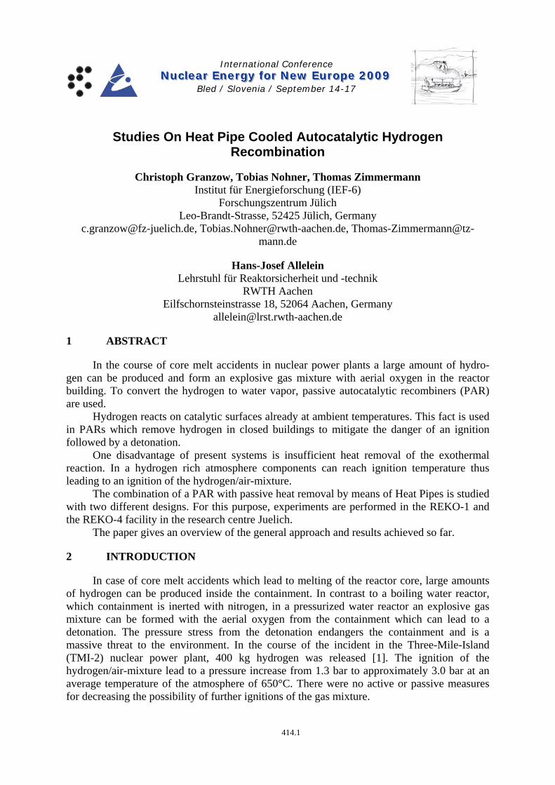
For the directly coated Heat Pipes, experiments were performed in the REKO-1 facility. The REKO-1 facility consists of a cylindrical forced flow channel. Inside the flow channel, the catalyst coated Heat Pipes are arranged. The hydrogen enriched gas mixture passes the heat pipes producing steam. At the outlet of the flow channel, a small gas flow is lead off to the gas analyzer. Experiments were performed regarding the efficiency of the hydrogen conversion and the temperature of the catalyst surface (Fig. 5).
414.5
Proceedings of the International Conference Nuclear Energy for New Europe, Bled, Slovenia, Sept. 14-17, 2009
Figure 5: REKO-1 facility with catalyst coated heat pipes
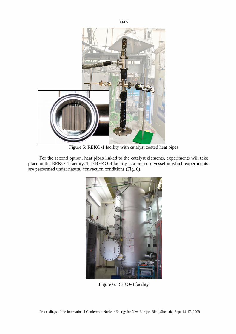
For the second option, heat pipes linked to the catalyst elements, experiments will take
place in the REKO-4 facility. The REKO-4 facility is a pressure vessel in which experiments are performed under natural convection conditions (Fig. 6).
Figure 6: REKO-4 facility

414.6
Proceedings of the International Conference Nuclear Energy for New Europe, Bled, Slovenia, Sept. 14-17, 2009
Heat pipes are linked vertical to catalyst coated sheets used in today’s PARs. The heat pipes are arranged in a way that the temperature of possible hotspots is below ignition temperature of the hydrogen/air-mixture under all conditions (Fig. 7).
Figure 7: Heat pipes linked to catalyst coated sheets
5 EXPERIMENTAL RESULTS
Experiments with directly catalyst coated Heat Pipes show that even at hydrogen concentrations of 10 vol.% the temperature on the surface of the catalyst doesn’t exceed 200 °C. For comparison, the same experiments were performed using a catalyst coated steel rod. The temperatures of the heat pipe cooled catalyst stay below the conventional ignition temperature of a hydrogen/air mixture, which is about 600°C (Fig. 8).
Figure 8: Temperatures on the catalyst surface of a heat pipe and a steel rod

414.7
Proceedings of the International Conference Nuclear Energy for New Europe, Bled, Slovenia, Sept. 14-17, 2009
A vital aspect when cooling the catalyst is the temperature dependency of the chemical
reaction. Below a particular temperature, in this case about 85°C, the reaction rate of the hydrogen-oxygen reaction is highly temperature dependent. If cooling is too efficient, the conversion efficiency may decrease significantly. Figure 9 shows the Arrhenius Plot of the reaction on coated heat pipes. At temperatures below about 85°C the reaction is surface controlled and highly temperature dependent. At higher temperatures the reaction is mass transfer controlled an there is only a small temperature dependence. Consequently, the heat pipe design aims at transferring the reaction as quick as possible into the mass transfer controlled region.
Figure 9: Arrhenius Plot of the hydrogen/air reaction
The efficiency of the hydrogen conversion is directly linked to the size of the catalyst
surface. In order to increase the size of the surface, experiments were performed using bundles of Heat Pipes. Although the efficiency doesn’t increase linear with the increase of the surface, using a bundle of 40 Heat Pipes leads to a conversion rate of about 70 % (Fig. 10). A conversion rate of 100 % is not achievable, given the fact that at low hydrogen concentrations the amount of heat produced by the exothermal reaction is not sufficient to heat up the catalyst surface temperature to an amount where the reaction can take place.

414.8
Proceedings of the International Conference Nuclear Energy for New Europe, Bled, Slovenia, Sept. 14-17, 2009
Figure 10: Efficiency of catalyst coated Heat Pipe bundles
6 CONCLUSIONS
The combination of a PAR with passive heat removal by means of Heat Pipes is currently investigated for two different options. First experimental results show that in an appropriate design, the temperature of the catalyst surface stays below the ignition temperature of the hydrogen/air mixture. If the heat pipes are arranged to a bundle of pipes, the efficiency of the set-up can be increased.
Future work will be the optimisation of the heatsink, in order to enable the surface temperatures to quickly reach the region of mass transfer controlled reaction. Passive heat removal of catalyst coated sheets linked with heat pipes will be examined as an option for a simple modification of today’s existing PARs.
7 REFERENCES
[1] W. Breitung: Wasserstoffverbrennung und Gebäudelasten bei schweren Kernreaktorunfällen, KfK-Nachrichten, Nr. 4, 1992, S. 192-211
[2] D. Reay, P. Kew: Heat Pipes – Theory, Design and Applications, Butterworth-Heinemann, 2006
[3] High-Capacity Catalytic Recombiners, Company leaflet, 1992
[4] E.-A. Reinecke: Reaktionskinetische Untersuchungen zur Auslegung von katalytischen Wasserstoffrekombinatoren, Dissertation an der RWTH Aachen, 1999
[5] A. Faghri: Heat Pipe Science and Technology, Taylor & Francis, New York, 1995
[6] VDI-Wärmeatlas, 9. Auflage, Springer Verlag, 2002