Student Participation in Formula SAE Design, Fabrication ...
14
Paper ID #30390 Student participation in Formula SAE design, fabrication, and testing as Capstone Experience Joshua Pierson, University of Georgia Joshua earned his bachelor’s degree in mechanical engineering from the University of Georgia. In 2019, he served as Vice President and powertrain lead for the university’s FSAE team. There he led powertrain design and development focusing on engine tuning and system integration. Joshua now works as a product engineer at a major automotive manufacturer, where he specializes in internal combustion engines. Dr. John M Mativo, University of Georgia Dr. John Mativo is Associate Professor at the University of Georgia. His research interest lies in two fields. The first is research focusing on best and effective ways to teaching and learning in STEM K- 16. He is currently researching on best practices in learning Dynamics, a sophomore engineering core course. The second research focus of Dr. Mativo is energy harvesting in particular the design and use of flexible thermoelectric generators. His investigation is both for the high-tech and low tech applications. In addition to teaching courses such as energy systems, mechanics, mechatronics, and production, he investigates best ways to expand cutting edge technologies to the workforce. Edwin Chiuz, University of Georgia Edwin earned his bachelor’s degree in mechanical engineering from the University of Georgia. There he served as team lead for the university’s FSAE program during the 2019 season. As a team leader, he focused on the design and manufacturing of the vehicle’s intake system, engine setup and final drive. Edwin currently works for a major car manufacturer in the state of Alabama, where he oversees the quality and functionality of automotive electrical components. Dr. Mark Trudgen, University of Georgia Is a lecturer in the School of Electrical and Computer Engineering in the College of Engineering. He has published in the area of automatic control systems. His research interests include undergraduate laboratory experience, remote labs, and advancing control theory in undergraduates. Dr. Christopher Herring, University of Georgia Chris is a faculty member of the School of Electrical and Computer Engineering in the College of Engi- neering at the University of Georgia. Chris’ dissertation work was in the area of engineering education specifically investigating academic help-seeking behavior in undergraduate engineering students with a particular interest in stereotype threat. Prior to UGA, Chris worked in education as a business manager, an IT adviser, and special topics in- structor in a local high school. He also volunteered as a SAT math instructor, a science and math tutor, and a robotics team coach. Chris worked for various corporations for over 20 years in microprocessor architecture, error correcting codes, and system architecture. Chris holds 21 patents, participated in many industry standard specification groups including PCI and SDRAM, presented at many conferences and proceedings including Comdex, CeBIT, CES, US Patent Office, IEEE Micro, and others. Chris has a bachelor’s and master’s degree in electrical engineering from Georgia Tech. Chris is married and has two sons. When he needs down time, Chris likes games of all types, hiking, sport shooting, and other outdoor activities. Chris also plays french horn in the local community band. c American Society for Engineering Education, 2020
Transcript of Student Participation in Formula SAE Design, Fabrication ...

Paper ID #30390
Student participation in Formula SAE design, fabrication, and testing asCapstone Experience
Joshua Pierson, University of Georgia
Joshua earned his bachelor’s degree in mechanical engineering from the University of Georgia. In 2019,he served as Vice President and powertrain lead for the university’s FSAE team. There he led powertraindesign and development focusing on engine tuning and system integration. Joshua now works as a productengineer at a major automotive manufacturer, where he specializes in internal combustion engines.
Dr. John M Mativo, University of Georgia
Dr. John Mativo is Associate Professor at the University of Georgia. His research interest lies in twofields. The first is research focusing on best and effective ways to teaching and learning in STEM K-16. He is currently researching on best practices in learning Dynamics, a sophomore engineering corecourse. The second research focus of Dr. Mativo is energy harvesting in particular the design and use offlexible thermoelectric generators. His investigation is both for the high-tech and low tech applications.In addition to teaching courses such as energy systems, mechanics, mechatronics, and production, heinvestigates best ways to expand cutting edge technologies to the workforce.
Edwin Chiuz, University of Georgia
Edwin earned his bachelor’s degree in mechanical engineering from the University of Georgia. Therehe served as team lead for the university’s FSAE program during the 2019 season. As a team leader,he focused on the design and manufacturing of the vehicle’s intake system, engine setup and final drive.Edwin currently works for a major car manufacturer in the state of Alabama, where he oversees the qualityand functionality of automotive electrical components.
Dr. Mark Trudgen, University of Georgia
Is a lecturer in the School of Electrical and Computer Engineering in the College of Engineering. Hehas published in the area of automatic control systems. His research interests include undergraduatelaboratory experience, remote labs, and advancing control theory in undergraduates.
Dr. Christopher Herring, University of Georgia
Chris is a faculty member of the School of Electrical and Computer Engineering in the College of Engi-neering at the University of Georgia. Chris’ dissertation work was in the area of engineering educationspecifically investigating academic help-seeking behavior in undergraduate engineering students with aparticular interest in stereotype threat.
Prior to UGA, Chris worked in education as a business manager, an IT adviser, and special topics in-structor in a local high school. He also volunteered as a SAT math instructor, a science and math tutor,and a robotics team coach. Chris worked for various corporations for over 20 years in microprocessorarchitecture, error correcting codes, and system architecture. Chris holds 21 patents, participated in manyindustry standard specification groups including PCI and SDRAM, presented at many conferences andproceedings including Comdex, CeBIT, CES, US Patent Office, IEEE Micro, and others. Chris has abachelor’s and master’s degree in electrical engineering from Georgia Tech. Chris is married and has twosons. When he needs down time, Chris likes games of all types, hiking, sport shooting, and other outdooractivities. Chris also plays french horn in the local community band.
c©American Society for Engineering Education, 2020

Student participation in Formula SAE design, fabrication,
and testing as Capstone Experience
Abstract
The impetus of capstone experience is to allow a student to use knowledge they have
cultivated and skills they have gained to design and develop a solution to a problem or to
innovate an existing artifact for better performance. The University of Georgia (UGA) recently
started a Society of Automotive Engineers (SAE) Collegiate Design Series (CDS) specifically
the Formula SAE (FSAE). The CDS “competitions take students beyond textbook theory by
enabling them to design, build, and test the performance of a real vehicle and then compete with
other students from around the globe in exciting and intense competitions” [1]. The FSAE
activities align with the capstone experience rationale.
This paper discusses the experience both the students and faculty had in the design, build,
and test of the powertrain. The powertrain is an extensive system since it provides the power and
transmission to develop motion of the vehicle. The presentation covers the background of FSAE
at UGA, the powertrain as part of the capstone experience, and the outcome.
This paper views involvement in capstone activities thorough Kolb’s Experiential Learning
Theory (ELT) [2], namely: concrete learning, reflective observation, abstract conceptualization
and active experimentation. Student class work learning is enhanced greatly by transfer of
abstract information to a concrete problem-solving activity.
Background
According the University of Georgia (UGA) College of Engineering Capstone Syllabus, a
capstone is a “two-semester sequence course that is project based and focused on problem
framing, stakeholder analysis, concept generation, and project management skills.” The goal “is
to review concepts in the design process and tools in design methodology with a focus on
engineering systems development cycle. Students working in multidisciplinary teams are
assigned to design problems that are open-ended, requiring creativity and involving iterative
solutions.” It continues to state that “Design systems will work independently with a faculty
mentor and adopts the design that can be rapid prototyped or manufactured and evaluated against
the design requirements. Student teams present their design concepts and final designs to
effectively demonstrate the technical and communication skills.” The course is only available to
undergraduate seniors.
In Fall 2018, the Formula SAE platform was started at UGA as part of its Motorsports
initiative which had its inception four years earlier. The College Dean of Engineering was
supportive of the student initiative and provided seed money. FSAE offers students a platform to

exercise their knowledge and skills. For this reason, a student does not have to be taking a
capstone credit to be part of the FSAE team. Capstone and non-capstone get to alongside each
other in the FSAE activities. Their roles are established at the beginning of Fall semester to
delineate expectations of the two groups of students. The capstone students are required to meet
all stated course requirements while non-capstone students are not. With this arrangement, the
FSAE faculty becomes a default mentor of the capstone students. Capstone students (hereafter
referred to as students) study the scope of their task, create an activity timeline (Gantt chart),
calculate forces, torques, etc. that pertain to their system, determine how their design fits with the
overall vehicle, propose and work within a given budget, identify parts or components to
purchase and propose vendors, and make a division of labor among its members. The students
keep an engineering notebook for the entire capstone experience in which they keep all the
activities they do include detailed design work. At regular intervals, faculty review student work
and provide feedback.
Sixty students joined the FSAE team in 2018. Nineteen of the sixty were Capstone students,
six of whom were part of powertrain sub-team. The powertrain design project was responsible
for the engine, air intake, exhaust, fueling, cooling, transmission, and final drive that powers the
Formula SAE car. These components were designed, acquired, fabricated, assembled, and tuned
by the powertrain design team to create a system to propel the vehicle.
The engine, for example, was sourced from a sport-bike motorcycle. It was modified and
rebuilt to comply with Formula SAE specifications. The engine was attached to a tube chassis,
fabricated by the frame team. The engine’s intake and exhaust were engineered using three-
dimensional modeling and fluid analysis. The fueling and cooling systems were modified and
custom engineered to optimized performance. The power from the engine channeled through a
transmission that had modified gear selection. The final drive was designed to transmit the
energy from the engine to the rear wheels. All of these components or sub-systems were
assembled and tuned to create an optimized and reliable powertrain. All custom parts were
designed in CAD and manufactured in house by the design team. The final product was a
synthesis of custom designed parts and OEM parts purchased to use on the car. A 3D model of
the final design was assembled in CAD and manufactured, tested, and optimized.
The entire design process was documented, and every decision formally entered and
explained in the design log. All data and analysis were logged and documented and included in
the design log. An overall design log was compiled and brought to competition to be scored by
the judges. The powertrain design, fabrication or acquisition, as described by students, follow.
Design stages
Fall semester was dedicated to design work while fabrication and assembly was done in
the Spring. The FSAE guidelines allow teams to design within certain limits. For example, for a
throttle actuation, we had a choice to use an electronic or mechanical one. We decided to use
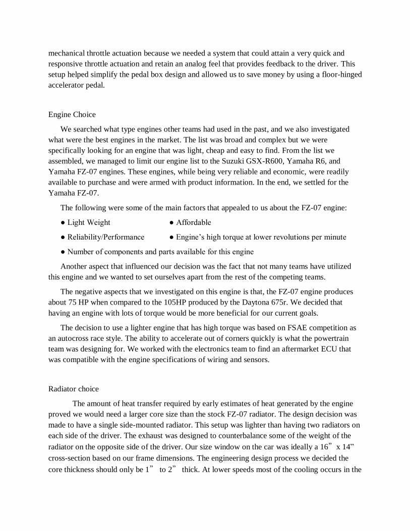
mechanical throttle actuation because we needed a system that could attain a very quick and
responsive throttle actuation and retain an analog feel that provides feedback to the driver. This
setup helped simplify the pedal box design and allowed us to save money by using a floor-hinged
accelerator pedal.
Engine Choice
We searched what type engines other teams had used in the past, and we also investigated
what were the best engines in the market. The list was broad and complex but we were
specifically looking for an engine that was light, cheap and easy to find. From the list we
assembled, we managed to limit our engine list to the Suzuki GSX-R600, Yamaha R6, and
Yamaha FZ-07 engines. These engines, while being very reliable and economic, were readily
available to purchase and were armed with product information. In the end, we settled for the
Yamaha FZ-07.
The following were some of the main factors that appealed to us about the FZ-07 engine:
● Light Weight ● Affordable
● Reliability/Performance ● Engine’s high torque at lower revolutions per minute
● Number of components and parts available for this engine
Another aspect that influenced our decision was the fact that not many teams have utilized
this engine and we wanted to set ourselves apart from the rest of the competing teams.
The negative aspects that we investigated on this engine is that, the FZ-07 engine produces
about 75 HP when compared to the 105HP produced by the Daytona 675r. We decided that
having an engine with lots of torque would be more beneficial for our current goals.
The decision to use a lighter engine that has high torque was based on FSAE competition as
an autocross race style. The ability to accelerate out of corners quickly is what the powertrain
team was designing for. We worked with the electronics team to find an aftermarket ECU that
was compatible with the engine specifications of wiring and sensors.
Radiator choice
The amount of heat transfer required by early estimates of heat generated by the engine
proved we would need a larger core size than the stock FZ-07 radiator. The design decision was
made to have a single side-mounted radiator. This setup was lighter than having two radiators on
each side of the driver. The exhaust was designed to counterbalance some of the weight of the
radiator on the opposite side of the driver. Our size window on the car was ideally a 16”x 14”
cross-section based on our frame dimensions. The engineering design process we decided the
core thickness should only be 1” to 2” thick. At lower speeds most of the cooling occurs in the
first couple inches of core. The size of the cross-section that is desired led us to search for
aftermarket radiators for small cars and sport-bikes. We utilized an electric cooling fan and fan
shroud to keep air flowing through the radiator at idle and lower speeds.
Intake design
Our first prototype, MK1, began as a sketch made out of straight lines, and was very
simplistic. The rough draft gave us the opportunity to visualize and create quick 3D
representations to aid us through the process. At this point in time, we agreed that our intake’s
manufacturing process would dictate its shape and complexity. Since funds were limited, we
opted for a design that could be easily 3D printed at our university. We converted the straight
simple lines from our rough draft into curves and rounded shapes that would enable a smooth
airflow within our system. Our MK1 intake design, consisted of 5 sections;
● Air filter and throttle body assembly ● Venturi Restrictor Tube (20mm Restrictor)
● Top Plenum ● Bottom Plenum with integrated runners
● Runners with integrated fuel injectors
We were able to design, manufacture and test our Venturi tube, top plenum and bottom plenum.
These 3 components were first designed as one whole component but then split into 3 sections
due to the fact that the 3D printers we were going to use had specific size limitations.
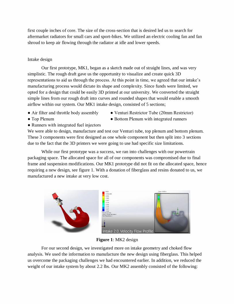
While our first prototype was a success, we ran into challenges with our powertrain
packaging space. The allocated space for all of our components was compromised due to final
frame and suspension modifications. Our MK1 prototype did not fit on the allocated space, hence
requiring a new design, see figure 1. With a donation of fiberglass and resins donated to us, we
manufactured a new intake at very low cost.
Figure 1: MK2 design
For our second design, we investigated more on intake geometry and choked flow
analysis. We used the information to manufacture the new design using fiberglass. This helped
us overcome the packaging challenges we had encountered earlier. In addition, we reduced the
weight of our intake system by about 2.2 lbs. Our MK2 assembly consisted of the following:

● 30mm, Single throttle body (1) ● Air filter (1)
● 5.5L fiberglass plenum, with integrated venturi tube (1) ● Rubber couplings (5)
● Aluminum brackets with fasteners (2) ● PVC connectors (2)
● FZ-07 stock runner assembly with fuel injectors (1)
Prior to manufacturing, we studied this latest intake assembly using flow simulations, in
SolidWorks (see figure 2). Once manufactured, it was installed on the engine block and tested.
The intake was tested for leaks and structural integrity by firing up our engine. No leaks were
present and the intake held its structural integrity under the engine’s generated vacuum. Our next
steps involved the tuning of our engine’s ECU and fuel tables. This is a crucial step ensured a
complete and successful integration between our intake and our power unit.
Figure 2: Simulation
Our guiding equation for mass flow rate was:

We decided to run on standard gasoline, enabling us to design our intake restrictor to be
limited at 20 mm in diameter. The design allowed us to maximize the air drawn into the air
intake. Table 1 presents calculations of the theoretical flow rates or air, through the 20mm
restriction at given RPMs and volumetric efficiencies. These were calculated using the engine’s
specifications and choked flow analysis equations. The red-shaded cells, are the RPMs at which
our system will reach choked flow, meaning that our engine will not be getting enough air to
fulfill its combustion processes.
Table 1: Sample results for our mass flow rate calculations
Exhaust design
Using the 2018 FSAE Rules as a guide, we researched how an exhaust system works and
how other FSAE teams had designed their exhaust systems in the past. Our engine required a
two-header system, we therefore searched automotive systems that incorporated such desings.
We explored on optimal total exhaust length, pipe diameter, and location where the pipes join
back together. Each of these factors affect the car’s RPMs, speed of throttle response, and back
pressure in the exhaust system. We found a pipe diameter of 1.375 inches provides sufficient
flow for engine speeds up to 8,000 RPMs. We purchased an FZ-07 exhaust manifold to obtain
the headers that connect to the engine. Next, we purchased piping and fabricate the rest of the
exhaust system matching that of the FZ-07 exhaust.
Two other considerations were a muffler to manage the exhaust noise, and an oxygen (O2)
sensor for monitoring fuel/air mix. Fortunately, the FZ-07 manifold we purchased came with the
stock muffler. The muffler met the sound requirements needed. As for the O2 sensor, we learned
that it should ideally be positioned at least 24 inches away from the exhaust ports to ensure that
its measurements are accurate.
The final step in the design process was building the car. Over the duration of the spring
semester, we spent countless hours in the shop putting the seemingly endless number of pieces
together. Our team built the powertrain. We also worked with all of the other FSAE capstone
teams to determine where all components fit in the race car. This step was imperative because
our project was not limited to the bounds described by a powertrain system. We were responsible
for building the entirety of the race car and that entails making sure everything fits together and
runs as it should.
Fuel systems
FSAE required that the fuel tank must be capable of being filled without manipulating the
tank or vehicle, air cavities or other effects that could cause an incorrect fuel level reading during
fueling should be prevented, and spillage during refueling cannot contact the driver position,
exhaust system, hot engine parts, or the ignition system. Further, FSAE fuel systems are defined
by the following 6 major categories:
● Fuel ● Fuel Tank
● Filler Neck/Sight Tube ● Venting systems
● Fuel Lines ● Fuel Injection
Each of these categories need to be carefully designed for so that all requirements are met.
Fuel tank
We built a fuel tank (figure 3) out of stainless steel for several reasons. Stainless steel
offers a very high corrosion resistance that most metals cannot offer. Compared to aluminum,

stainless steel is more resistive in the presence of ethanol in the gasoline mixture. We had
initially given thought to making the tank out of the same fiberglass composite that the intake
was made out of. This material would have been much cheaper than a metal tank, but we were
unsure if it could withstand contact with gasoline and ethanol over an extended period of time.
For this reason, we conducted an experiment of our own to determine if that composite
would be suitable for a fuel tank. After leaving some small “coupons” of the material submerged
in regular unleaded gasoline for 32 days, we found that significant material degradation had
occurred. There was noticeable buildup of particles (figure 4) in the bottom of the container that
the experiment had been conducted in, and the coupons had experienced approximately 50% of
material loss and a decrease in stiffness. Figure 3 shows a CAD drain of the final design. Figure
4 shows the degradation of the composite material.
Figure 3: Final design of gas tank Figure 4: Fiberglass in gasoline
Fuel lines
When designing the fuel system layout, we had to decide on what components to include
in the system (figure 5).
Figure 5: line and components
As seen by the layout, two fuel filters were used to ensure clean fuel in the system. A
high flow, 80-100-micron filter was located just outside the tank. This allowed the pump to pull a
high volume of fuel from the tank to pressurize into the fuel lines while also protecting the pump

from larger particles. A 20-micron filter was placed after the fuel pump to remove any fine
particles from the fuel supply that could clog the fuel injectors or cause buildup in the
combustion chamber. The fuel pressure regulator help maintain a solid fuel pressure to the fuel
injectors by releasing excess pressure and sending fuel back to the tank.
Fuel injection
Our vehicle used low pressure injection (LPI). According to the FSAE rules, the flexible
fuel lines of LPI systems must either be a metal braided hose with either crimped on or reusable,
threaded fittings or be a reinforced rubber hose with some form of abrasion resistant protection.
Unmodified OEM fuel rails are always acceptable. Non-OEM rails made of plastic, carbon fiber,
or rapid prototyping flammable materials are prohibited. The fuel rail must be securely attached
to the manifold, engine block, or cylinder head with brackets and mechanical fasteners. We used
the stock fuel rail that came attached to the engine. We spent a lot of time working with the ECU
to fine tune the injection timing and air to fuel mixture entering the combustion chamber. Fuel
consumption is a major part of the judging process for FSAE teams, and any team that uses more
than 1.5 gallons for the Endurance event will automatically have 4 minutes added to their overall
time.
Final drive
We used a live axle chain drive(spool) because it was more time and cost effective for us,
it requires a simpler mounting configuration and it has the added benefit of allowing the use of
only one brake disk, reducing weight and cost. The biggest problem with this spool setup, was
the coupling between its cv joints and the tripods on our wheel hubs. In order to solve this issue,
we decided to modify one end of our axle shafts. Also, in order to further reduce costs, we
matched components from other types of vehicles; for instance, the wheel hubs of a Mazda
Miata, the chain tensioner from an ATV or the cv joints from older European cars. These
decisions saved us sizeable amounts of time and money. Figure 6 shows the final drive.
Figure 6: Our final drive

Components that formed our final drive assembly were:
● CV Joints (2) ● Half shafts (2)
● Shaft Tripods (2) ● Outboard Tripod Housing (2)
● Mazda wheel hubs (2) ● Rubber boots (4)
● Sprocket /Chain gear (1) ● ATV Chain tensioner (1)
● Support Bearings (2) ● Sprocket and disk brake adapters (2)
● Spool with casing (1) ● Rear single brake disc (1)
● Rear single brake caliper (1)
Cost
The total cost for the powertrain was $5,284.93. Material cost was $5,090.58, process
cost was 110.57, fasteners cost $83.78, and tooling cost was $0.
Competition
Two of the powertrain team capstone members and their mentor participated in the
Lincoln, Nebraska SAE competitions. Their reflections and the three other members follow. The
instructor reflection concludes the experiences learned.
Reflections from students - Sample
Student 1:
This project has been a life changing experience that has positively influenced my
personal, educational and professional life. Through this project, I have been able to implement a
lot of concepts and knowledge obtained through my college career. I have been able to put this
knowledge to work and also improve it. Before this project, my computational and technical
engineering skills were almost nonexistent.
So far, I have been able to familiarize myself with computational simulations, 3D model
creation, additive manufacturing, machining and composite manufacturing. I also have been able
to experience ‘real-world situations’ within this project. For instance, our stakeholders expect
positive results and performance from our final product, even though we are working with time
and monetary constraints. This is a typical situation in the motorsport industry, which is where I
am steering my career towards. This not only strengthen my technical skills, but it also
strengthened my resume and job application materials. All in all, this capstone project has given
me the opportunity to get a great and instructive real-world experience while still being inside a
more forgiving environment.

Student 2 (Powertrain Lead)
I led the powertrain team in the design process and overall integration throughout the
project. I specialized in the engine selection, component integration, engine tuning, final drive,
and testing. This project gave me the opportunity to gain valuable experience in component
design, 3D modeling, engine tuning, and manufacturing techniques. Throughout the entire
project I gained in-depth understanding on how each component in the powertrain scope is
designed and integrated into the system. Throughout the semester I lead a weekly design meeting
to keep the team on task and promote progress with problem solving. I have gained expertise in
engine cooling systems, air intake systems, engine mapping, driveshaft design, machine design
force calculations, and vehicle design. I hope to utilize these skills to get a career I enjoy.
This project and design process have allowed me to gain experience directly related to the
skills I hope to master in my career. Coordinating a complex engineering project is a skill that
cannot be properly taught in a classroom and is not included with a university diploma upon
graduation. The FSAE design process requires a multitude of valuable skills that are valuable to
employers as well as valuable to my own personal engineering project goals. My involvement in
FSAE and the powertrain capstone project is a highlight of my college undergrad career and I
regard it as valuable as a co-op or internship from an elite company. Skills that I have
strengthened in the first semester of design include 3D modeling and simulation, strength and
failure analysis, manufacturing processes, designing a complex machine with many interworking
components.
Student 3:
I spent the majority of my time working on the car’s exhaust system. I lead the exhaust
team by conducting research on each of the parts and making a decision on which parts would be
best to incorporate into the car’s design. Each of these parts also needed to be found online at a
price that fit into our budget. When it came time to manufacture, I assisted in both the design
decisions associated with the exhaust and the actual building of the exhaust. I aided the students
working on final drive by researching how our system will operate and finding the right parts
that fit together. Additionally, I assisted in manufacturing the final design of the car’s intake,
along with any other components of the car that were being manufactured while I was in the
shop. I played a big role in writing and compiling the design report. Our team was required to
submit a design report to the FSAE judges. The design report outlined our design choices and
how everything was placed on the car. I also worked on the cost report by recording the amount
of and type of fasteners or bolts each part of the powertrain required.
My favorite part of being on the FSAE powertrain design team is how much I have
learned. Coming into the project I knew very little about cars and how their powertrain systems
operated. I was privileged to be given my own section of the car to research and understand, as
well as, the ability to work with intelligent people on every other component of powertrain. The
vast knowledge everyone brings to the club has really impacted me. I am thrilled every time I go
into one of our meetings because I learn more about automotive each time. I believe this will
help me tremendously in the future. Whether I am applying for jobs, working on my own
vehicle, or simply working on another project, I will be well equipped with the knowledge I have
gained through FSAE powertrain capstone.
Student 4:
I was placed in charge of researching and developing the fuel systems for the car. This
included the overall layout of the fuel lines and the design of the fuel tank. Once those portions
of the car were finished being designed, I helped research and develop the design of our own
engine test stand that we will be building ourselves.
I came into this project knowing very little about cars or if I would even be interested in
working in the automotive industry in the future, but I have awakened a passion in me that I
didn’t know I had. I had a lot of catching up to do to try to fully understand what makes an FSAE
car run effectively for competition, and I hope to apply what I have learned in a future career in
the automotive industry. I even attended a course to learn how to weld so that I could help build
some of the components. That is a skill that I never thought I’d be able to acquire. We have had a
wonderful team to work with, and the support across all areas of design has been overwhelming.
Putting together a working, competitive car from scratch is a tremendous undertaking, and the
teamwork and leadership skills that we have built to overcome that task will not easily be
forgotten. Working with the FSAE team at UGA on this project has been an amazing
opportunity.
Student 5:
I was involved in researching fuel maps and basic tuning methods for the engine, as well
as selection of which engine we wanted to run after we decided not to go with the Daytona 675r.
I also assisted Edwin in the design and manufacturing process of the air intake system. After we
finished the intake, I helped with designing the final drive of the vehicle.
This project has taught me a lot about just how much goes into designing a running car
from the ground up. There are so many systems and parts that all must work together. This
project also helped teach me how to work with time and monetary constraints, as well as
working with several team members. It taught me how to organize sub teams and keep members
on task and motivated in order to get participation out of everyone. This project has also assured
me that I do want to pursue a career in the automotive industry. This project is the closest I have
come to a real-world project and really opened my eyes to how it works in the real world.

Instructor
In my undergraduate engineering experience, I had participated in the SAE Baha CDS
and competition. It was a great moment to learn why components and systems were designed the
way they were. The experience added value to learning. It was rewarding to work with students
to develop the first ever FSAE from the University of Georgia. Students saw relevance of course
work as they worked in their sub teams. The powertrain sub-team capstone members were
required to have taken dynamics, thermal dynamics, and heat transfer at the minimal. Each sub-
team had minimal required coursework related to those specific systems. Also, an emphasis was
placed that the faculty were resources and could be asked for guidance, if necessary. Details of
work were to be documented in the Engineering Design books and I reviewed them at mid-term
and end of semester. I also received by weekly reports from the capstone teams. Overall, it is a
platform for real life design and fabrication work. Vehicle dynamics gives insight into the forces
and performance requirements of a formula race car and the considerations that need to be
included in the design. Students in the powertrain group were able to learn and teach each other
aspects of vehicle dynamics that are important in powertrain design. Kolb’s ELT enhances
learning as attested by students and instructor above
Conclusion
The Capstone course is intended for the student to apply acquired knowledge, skills and
attitude in problem solving. The Formula SAE provides a platform for capstone experiences to
be realized. The design and building of powertrain for the Formula SAE was an excellent
platform for students to apply their course work experiences in real world engineering design and
fabrication work. The students’ performance was satisfactory and they met expectations!
References
[1] Formula SAE https://www.fsaeonline.com/ retrieved January 2020
[2] McLoed, Saul (2017 update) https://www.simplypsychology.org/learning-kolb.html retrieved
January 2020