Student Notes: Lesson 3: Surface Creation - Freeyvonet.florent.free.fr/SERVEUR/COURS CATIA/CATIA...
91
Student Notes: CATIA V5 Surface Design- Lesson 3: Surface Creation Copyright DASSAULT SYSTEMES 3-1 Copyright DASSAULT SYSTEMES Lesson 3: Surface Creation In this lesson, you will learn how to create surfaces from wireframes. Lesson Contents: Case Study: Surface Creation Design Intent Stages in the Process Choice of Surface Sweeping a Profile Create a Multi-Section Surface Create an Adaptive Sweep Surface Duration: Approximately 3 Hours
Transcript of Student Notes: Lesson 3: Surface Creation - Freeyvonet.florent.free.fr/SERVEUR/COURS CATIA/CATIA...
Student Notes:
CATIA V5 Surface Design- Lesson 3: Surface Creation������������
Copyright DASSAULT SYSTEMES 3-1
Cop
yrig
ht D
AS
SA
ULT
SY
ST
EM
ES
Lesson 3: Surface CreationIn this lesson, you will learn how to create surfaces from wireframes.
Lesson Contents:
Case Study: Surface CreationDesign IntentStages in the ProcessChoice of SurfaceSweeping a ProfileCreate a Multi-Section SurfaceCreate an Adaptive Sweep Surface
Duration: Approximately 3 Hours
Student Notes:
CATIA V5 Surface Design- Lesson 3: Surface Creation������������
Copyright DASSAULT SYSTEMES 3-2
Cop
yrig
ht D
AS
SA
ULT
SY
ST
EM
ES
Case Study: Surface Creation
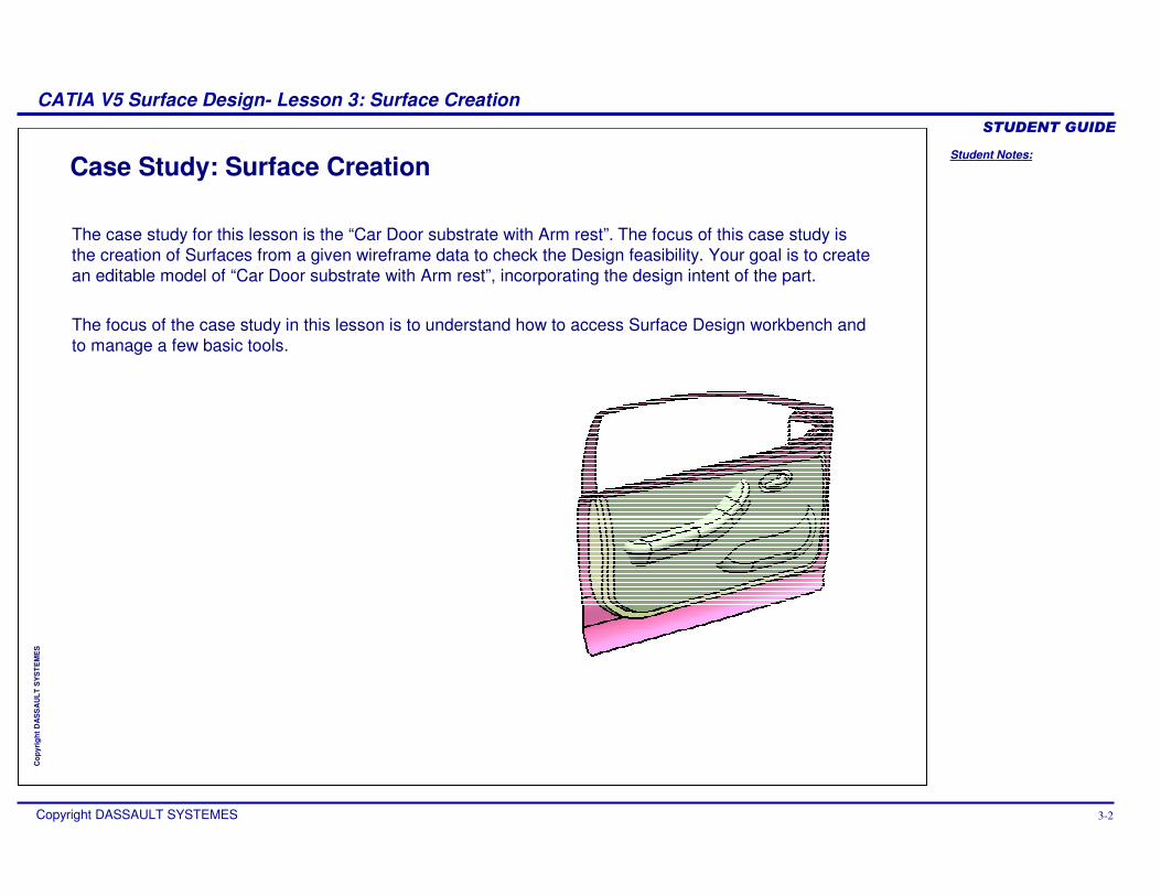
The case study for this lesson is the “Car Door substrate with Arm rest”. The focus of this case study is the creation of Surfaces from a given wireframe data to check the Design feasibility. Your goal is to create an editable model of “Car Door substrate with Arm rest”, incorporating the design intent of the part.
The focus of the case study in this lesson is to understand how to access Surface Design workbench and to manage a few basic tools.
Student Notes:
CATIA V5 Surface Design- Lesson 3: Surface Creation������������
Copyright DASSAULT SYSTEMES 3-3
Cop
yrig
ht D
AS
SA
ULT
SY
ST
EM
ES
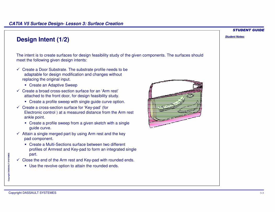
Design Intent (1/2)
� Create a Door Substrate. The substrate profile needs to be adaptable for design modification and changes without
replacing the original input.� Create an Adaptive Sweep
� Create a broad cross-section surface for an ‘Arm rest’attached to the front door, for design feasibility study.� Create a profile sweep with single guide curve option.
� Create a cross-section surface for ‘Key-pad’ (for Electronic control ) at a measured distance from the Arm rest ankle point.� Create a profile sweep from a given sketch with a single
guide curve.� Attain a single merged part by using Arm rest and the key
pad component.� Create a Multi-Sections surface between two different
profiles of Armrest and Key-pad to form an integrated single part.
� Close the end of the Arm rest and Key-pad with rounded ends.� Use the revolve option to attain the rounded ends.
The intent is to create surfaces for design feasibility study of the given components. The surfaces should meet the following given design intents:
Student Notes:
CATIA V5 Surface Design- Lesson 3: Surface Creation������������
Copyright DASSAULT SYSTEMES 3-4
Cop
yrig
ht D
AS
SA
ULT
SY
ST
EM
ES
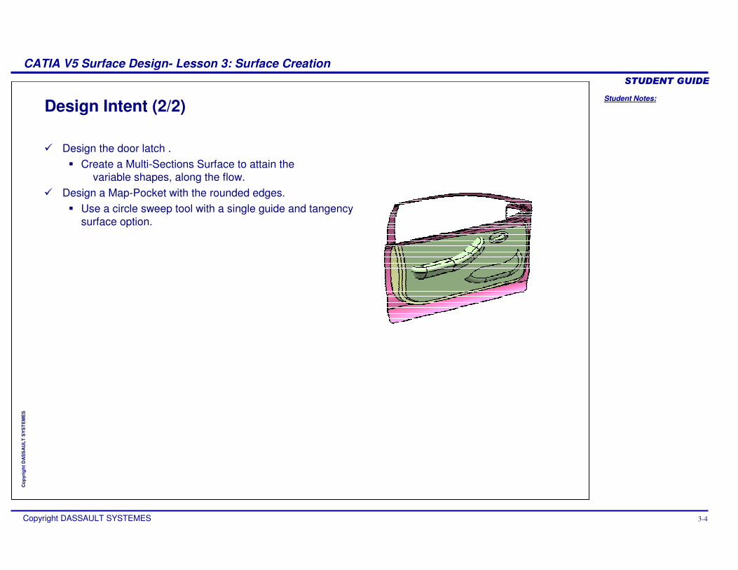
Design Intent (2/2)
� Design the door latch .� Create a Multi-Sections Surface to attain the
variable shapes, along the flow.� Design a Map-Pocket with the rounded edges.
� Use a circle sweep tool with a single guide and tangency surface option.
Student Notes:
CATIA V5 Surface Design- Lesson 3: Surface Creation������������
Copyright DASSAULT SYSTEMES 3-5
Cop
yrig
ht D
AS
SA
ULT
SY
ST
EM
ES
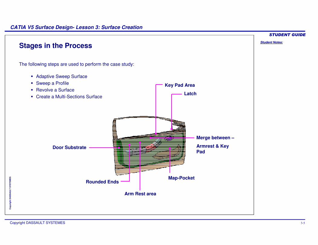
Stages in the Process
The following steps are used to perform the case study:
� Adaptive Sweep Surface� Sweep a Profile� Revolve a Surface� Create a Multi-Sections Surface
Arm Rest area
Door Substrate
Key Pad Area
Merge between –
Armrest & Key Pad
Map-Pocket
Latch
Rounded Ends
Student Notes:
CATIA V5 Surface Design- Lesson 3: Surface Creation������������
Copyright DASSAULT SYSTEMES 3-6
Cop
yrig
ht D
AS
SA
ULT
SY
ST
EM
ES
Step 1: Choice of Surfaces
In this section, you will be introduced to the different types of ‘Surface Creation’tools available in Generative Shape Design.
Use the following steps:1. Choice of Surfaces2. Extruding or Revolving a Profile3. Sweep a Profile4. Create Multi-Section Surface5. Create an Adaptive Sweep
Surface
Student Notes:
CATIA V5 Surface Design- Lesson 3: Surface Creation������������
Copyright DASSAULT SYSTEMES 3-7
Cop
yrig
ht D
AS
SA
ULT
SY
ST
EM
ES
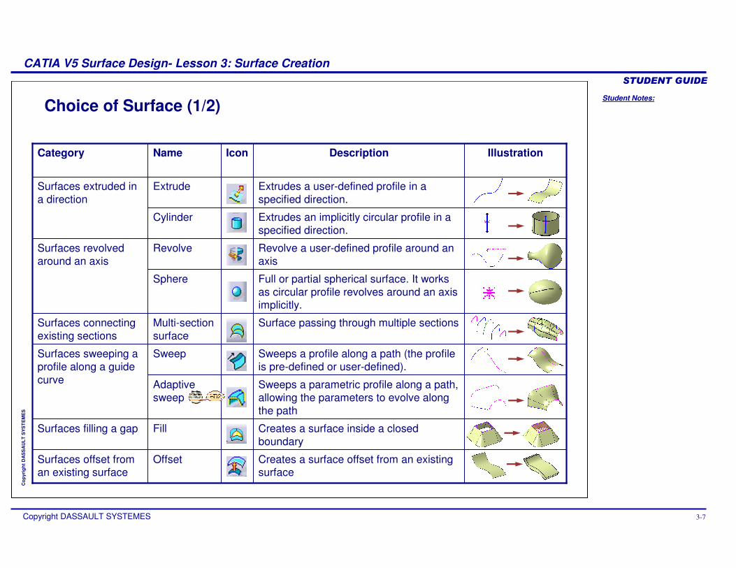
Choice of Surface (1/2)
Creates a surface offset from an existing surface
OffsetSurfaces offset from an existing surface
Creates a surface inside a closed boundary
FillSurfaces filling a gap
Sweeps a parametric profile along a path, allowing the parameters to evolve along the path
Adaptive sweep
Sweeps a profile along a path (the profile is pre-defined or user-defined).
SweepSurfaces sweeping a profile along a guide curve
Surface passing through multiple sectionsMulti-section surface
Surfaces connecting existing sections
Full or partial spherical surface. It works as circular profile revolves around an axis implicitly.
Sphere
Revolve a user-defined profile around an axis
RevolveSurfaces revolved around an axis
Extrudes an implicitly circular profile in a specified direction.
Cylinder
Extrudes a user-defined profile in a specified direction.
ExtrudeSurfaces extruded in a direction
IllustrationDescriptionIconNameCategory
Student Notes:
CATIA V5 Surface Design- Lesson 3: Surface Creation������������
Copyright DASSAULT SYSTEMES 3-8
Cop
yrig
ht D
AS
SA
ULT
SY
ST
EM
ES
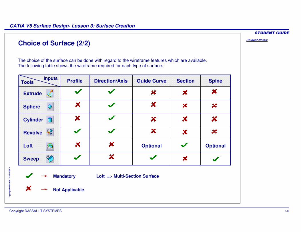
Choice of Surface (2/2)
The choice of the surface can be done with regard to the wireframe features which are available. The following table shows the wireframe required for each type of surface:
Section
OptionalOptionalLoft
Revolve
Sweep
Cylinder
Sphere
Extrude
SpineGuide CurveDirection/AxisProfile
Mandatory
Not Applicable
InputsTools
Loft => Multi-Section Surface
Student Notes:
CATIA V5 Surface Design- Lesson 3: Surface Creation������������
Copyright DASSAULT SYSTEMES 3-9
Cop
yrig
ht D
AS
SA
ULT
SY
ST
EM
ES
Step 2: Extruding or Revolving A Profile
In this section you will learn to create a basic surface.
Use the following steps:
1. Choice of Surfaces
2. Extruding or Revolving a Profile
3. Sweep a Profile4. Create Multi-Section Surface5. Create an Adaptive Sweep
Surface
Student Notes:
CATIA V5 Surface Design- Lesson 3: Surface Creation������������
Copyright DASSAULT SYSTEMES 3-10
Cop
yrig
ht D
AS
SA
ULT
SY
ST
EM
ES
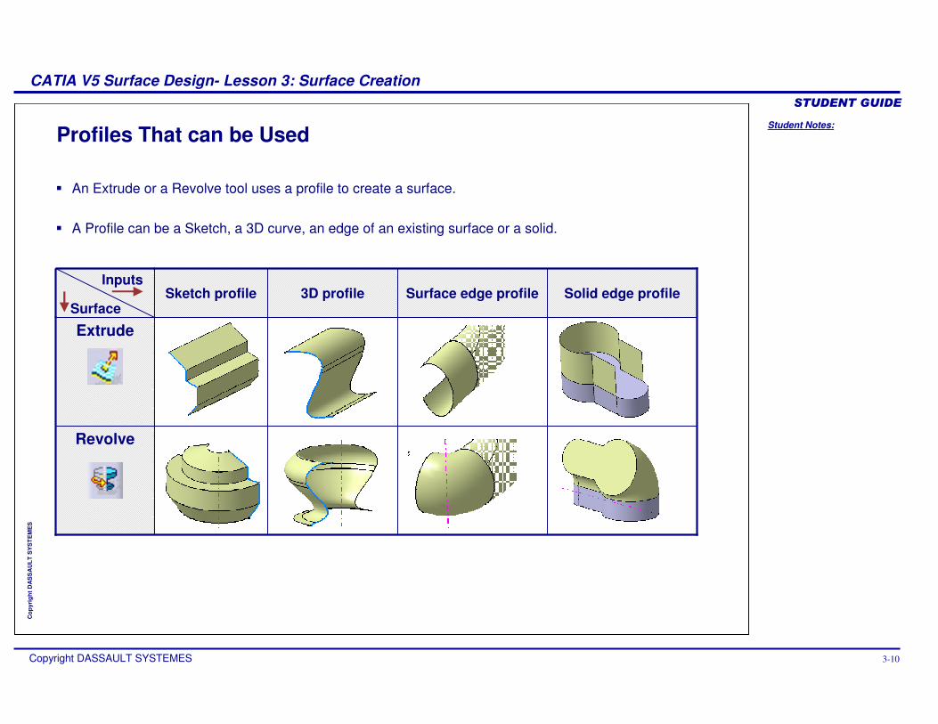
Profiles That can be Used
� An Extrude or a Revolve tool uses a profile to create a surface.
� A Profile can be a Sketch, a 3D curve, an edge of an existing surface or a solid.
Revolve
Extrude
Solid edge profileSurface edge profile3D profileSketch profileInputs
Surface
Student Notes:
CATIA V5 Surface Design- Lesson 3: Surface Creation������������
Copyright DASSAULT SYSTEMES 3-11
Cop
yrig
ht D
AS
SA
ULT
SY
ST
EM
ES
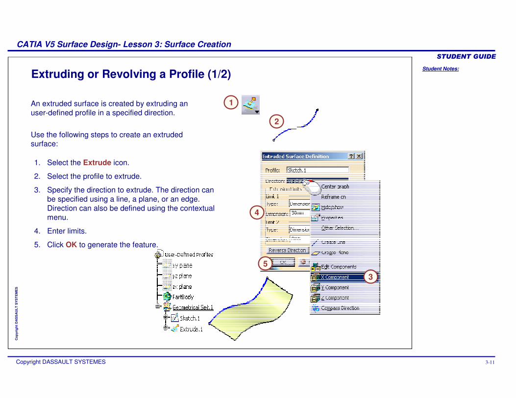
Extruding or Revolving a Profile (1/2)
An extruded surface is created by extruding an user-defined profile in a specified direction.
Use the following steps to create an extruded surface:
1. Select the Extrude icon.
2. Select the profile to extrude.
3. Specify the direction to extrude. The direction can be specified using a line, a plane, or an edge. Direction can also be defined using the contextual menu.
4. Enter limits.
5. Click OK to generate the feature.
1
2
3
5
4
Student Notes:
CATIA V5 Surface Design- Lesson 3: Surface Creation������������
Copyright DASSAULT SYSTEMES 3-12
Cop
yrig
ht D
AS
SA
ULT
SY
ST
EM
ES
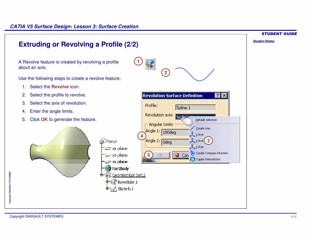
Extruding or Revolving a Profile (2/2)
A Revolve feature is created by revolving a profile about an axis.
Use the following steps to create a revolve feature:
1. Select the Revolve icon.
2. Select the profile to revolve.
3. Select the axis of revolution.
4. Enter the angle limits.
5. Click OK to generate the feature.
5
43
1
2
Student Notes:
CATIA V5 Surface Design- Lesson 3: Surface Creation������������
Copyright DASSAULT SYSTEMES 3-13
Cop
yrig
ht D
AS
SA
ULT
SY
ST
EM
ES
13
Step 3: Sweeping a Profile
In this section, you will learn about the different types of Sweep surface tools.
Use the following steps:
1. Choice of Surfaces 2. Extruding or Revolving a
Profile
3. Sweep a Profile4. Create Multi-Section Surface5. Create an Adaptive Sweep
Surface
Student Notes:
CATIA V5 Surface Design- Lesson 3: Surface Creation������������
Copyright DASSAULT SYSTEMES 3-14
Cop
yrig
ht D
AS
SA
ULT
SY
ST
EM
ES
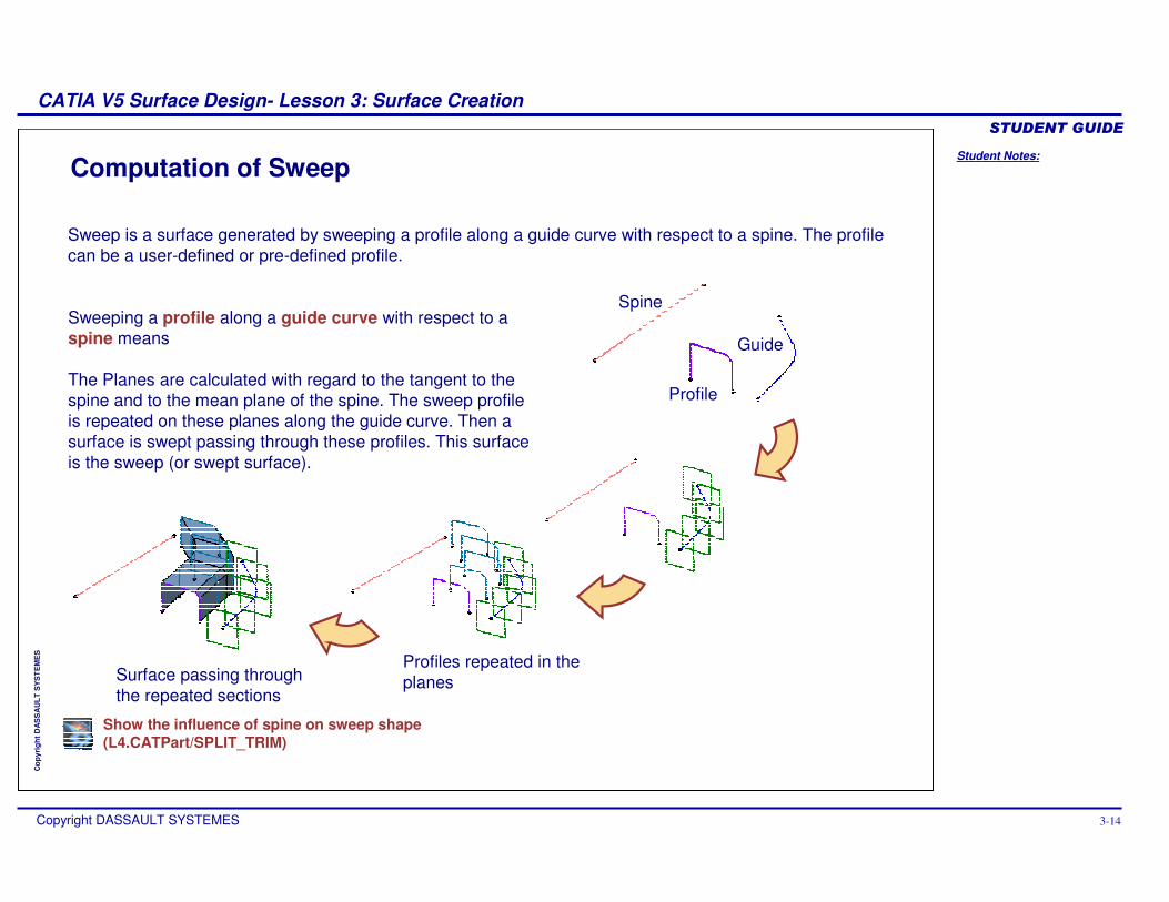
Computation of Sweep
Sweep is a surface generated by sweeping a profile along a guide curve with respect to a spine. The profile can be a user-defined or pre-defined profile.
Sweeping a profile along a guide curve with respect to a spine means
The Planes are calculated with regard to the tangent to the spine and to the mean plane of the spine. The sweep profile is repeated on these planes along the guide curve. Then a surface is swept passing through these profiles. This surface is the sweep (or swept surface).
Profile
Spine
Guide
Profiles repeated in the planesSurface passing through
the repeated sections
Show the influence of spine on sweep shape(L4.CATPart/SPLIT_TRIM)
Student Notes:
CATIA V5 Surface Design- Lesson 3: Surface Creation������������
Copyright DASSAULT SYSTEMES 3-15
Cop
yrig
ht D
AS
SA
ULT
SY
ST
EM
ES
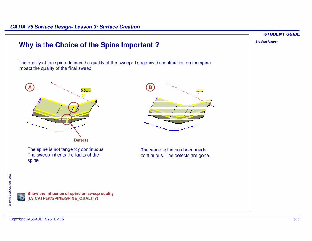
Why is the Choice of the Spine Important ?
The quality of the spine defines the quality of the sweep: Tangency discontinuities on the spine impact the quality of the final sweep.
The spine is not tangency continuousThe sweep inherits the faults of the spine.
The same spine has been made continuous. The defects are gone.
A B
Show the influence of spine on sweep quality(L3.CATPart/SPINE/SPINE_QUALITY)
Defects
Student Notes:
CATIA V5 Surface Design- Lesson 3: Surface Creation������������
Copyright DASSAULT SYSTEMES 3-16
Cop
yrig
ht D
AS
SA
ULT
SY
ST
EM
ES
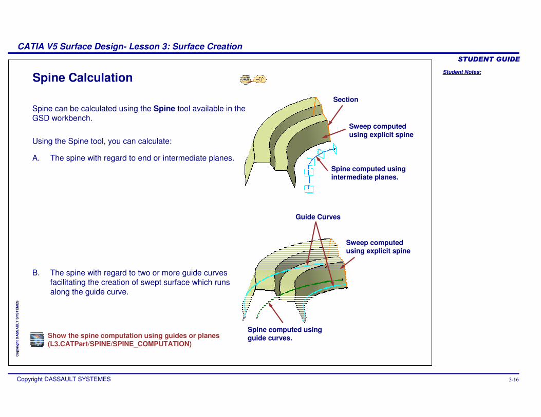
Spine Calculation
Spine can be calculated using the Spine tool available in the GSD workbench.
Using the Spine tool, you can calculate:
A. The spine with regard to end or intermediate planes.
B. The spine with regard to two or more guide curves facilitating the creation of swept surface which runs along the guide curve.
Spine computed using intermediate planes.
Spine computed using guide curves.
Section
Sweep computed using explicit spine
Guide Curves
Sweep computed using explicit spine
Show the spine computation using guides or planes(L3.CATPart/SPINE/SPINE_COMPUTATION)
Student Notes:
CATIA V5 Surface Design- Lesson 3: Surface Creation������������
Copyright DASSAULT SYSTEMES 3-17
Cop
yrig
ht D
AS
SA
ULT
SY
ST
EM
ES
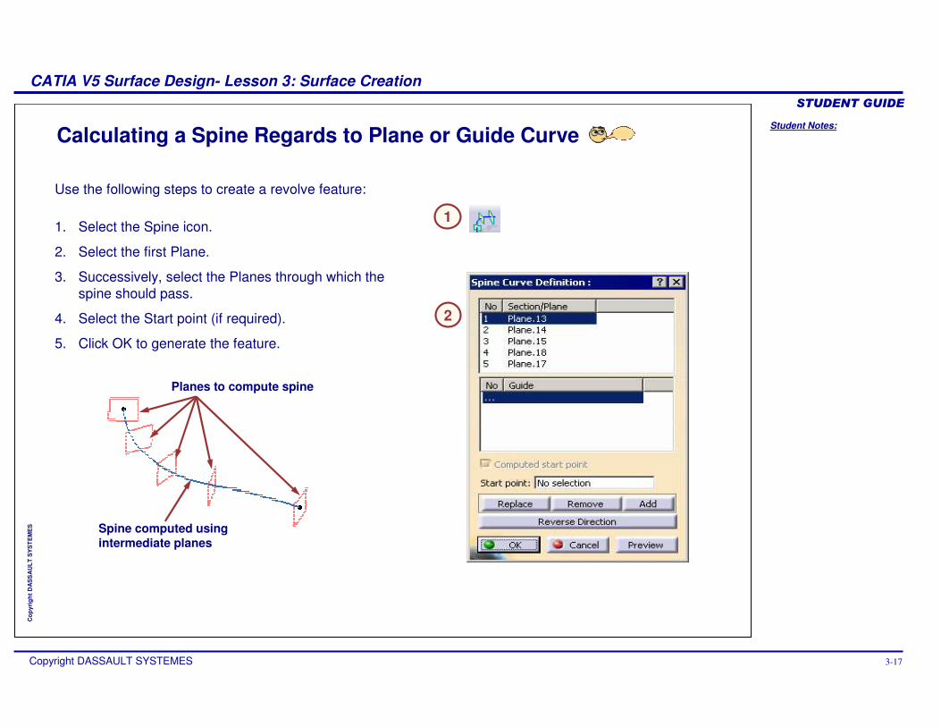
Calculating a Spine Regards to Plane or Guide Curve
1
2
1. Select the Spine icon.
2. Select the first Plane.
3. Successively, select the Planes through which the spine should pass.
4. Select the Start point (if required).
5. Click OK to generate the feature.
Use the following steps to create a revolve feature:
Planes to compute spine
Spine computed using intermediate planes
Student Notes:
CATIA V5 Surface Design- Lesson 3: Surface Creation������������
Copyright DASSAULT SYSTEMES 3-18
Cop
yrig
ht D
AS
SA
ULT
SY
ST
EM
ES
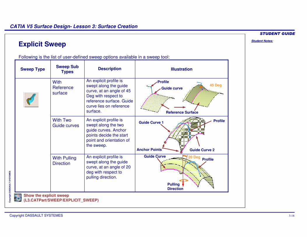
Following is the list of user-defined sweep options available in a sweep tool:
Explicit Sweep
ProfileGuide Curve 1
Guide Curve 2
Guide Curve
Pulling Direction
Reference Surface
Profile
Profile
Guide curve
Anchor Points
20 Deg
45 Deg
Show the explicit sweep(L3.CATPart/SWEEP/EXPLICIT_SWEEP)
An explicit profile is swept along the guide curve, at an angle of 20 deg with respect to pulling direction.
An explicit profile is swept along the two guide curves. Anchor points decide the start point and orientation of the sweep.
An explicit profile is swept along the guide curve, at an angle of 45 Deg with respect to reference surface. Guide curve lies on reference surface.
IllustrationSweep Sub Types
With Pulling Direction
With Two Guide curves
Description
With Reference surface
Sweep Type
Student Notes:
CATIA V5 Surface Design- Lesson 3: Surface Creation������������
Copyright DASSAULT SYSTEMES 3-19
Cop
yrig
ht D
AS
SA
ULT
SY
ST
EM
ES
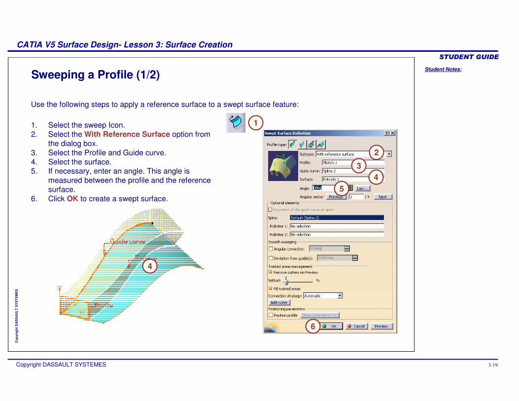
Sweeping a Profile (1/2)
Use the following steps to apply a reference surface to a swept surface feature:
1. Select the sweep Icon.2. Select the With Reference Surface option from
the dialog box.3. Select the Profile and Guide curve.4. Select the surface.5. If necessary, enter an angle. This angle is
measured between the profile and the reference surface.
6. Click OK to create a swept surface.
1
4
3
2
5
6
4
Student Notes:
CATIA V5 Surface Design- Lesson 3: Surface Creation������������
Copyright DASSAULT SYSTEMES 3-20
Cop
yrig
ht D
AS
SA
ULT
SY
ST
EM
ES
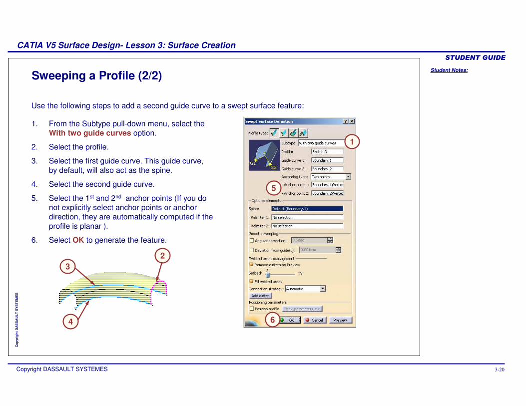
Sweeping a Profile (2/2)
Use the following steps to add a second guide curve to a swept surface feature:
1. From the Subtype pull-down menu, select the With two guide curves option.
2. Select the profile.
3. Select the first guide curve. This guide curve, by default, will also act as the spine.
4. Select the second guide curve.
5. Select the 1st and 2nd anchor points (If you do not explicitly select anchor points or anchor direction, they are automatically computed if the profile is planar ).
6. Select OK to generate the feature.
1
6
32
4
5
Student Notes:
CATIA V5 Surface Design- Lesson 3: Surface Creation������������
Copyright DASSAULT SYSTEMES 3-21
Cop
yrig
ht D
AS
SA
ULT
SY
ST
EM
ES
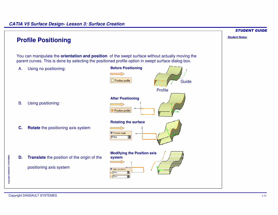
You can manipulate the orientation and position of the swept surface without actually moving the parent curves. This is done by selecting the positioned profile option in swept surface dialog box.
Profile Positioning
Before PositioningA. Using no positioning:
B. Using positioning:
C. Rotate the positioning axis system
D. Translate the position of the origin of the
positioning axis system
After Positioning
Rotating the surface
Profile
Guide
Modifying the Position axis system
Student Notes:
CATIA V5 Surface Design- Lesson 3: Surface Creation������������
Copyright DASSAULT SYSTEMES 3-22
Cop
yrig
ht D
AS
SA
ULT
SY
ST
EM
ES
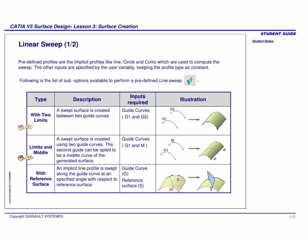
Linear Sweep (1/2)
Pre-defined profiles are the Implicit profiles like line, Circle and Conic which are used to compute the sweep. The other inputs are specified by the user variably, keeping the profile type as constant.
Following is the list of sub -options available to perform a pre-defined Line sweep :
Guide Curve (G)Reference surface (S)
An implicit line profile is swept along the guide curve at an specified angle with respect to reference surface.
With Reference
Surface
Guide Curves( G1 and M )
A swept surface is created using two guide curves. The second guide can be opted to be a middle curve of the generated surface.
Limits and Middle
Guide Curves( G1 and G2)
A swept surface is created between two guide curvesWith Two
Limits
IllustrationInputs requiredDescriptionType
G1
G2
G1
M
G1
S
Student Notes:
CATIA V5 Surface Design- Lesson 3: Surface Creation������������
Copyright DASSAULT SYSTEMES 3-23
Cop
yrig
ht D
AS
SA
ULT
SY
ST
EM
ES
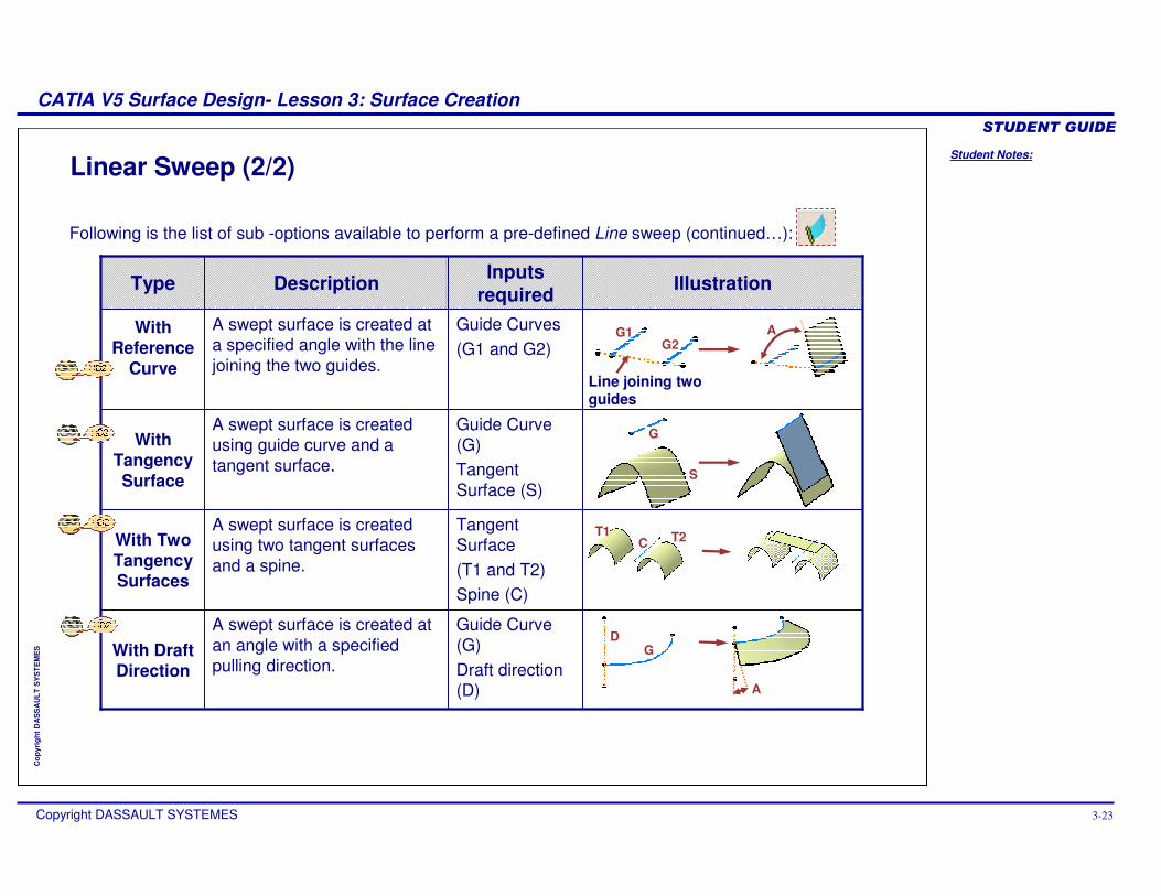
Linear Sweep (2/2)
Following is the list of sub -options available to perform a pre-defined Line sweep (continued…):
Tangent Surface (T1 and T2)Spine (C)
A swept surface is created using two tangent surfaces and a spine.
With Two Tangency Surfaces
Guide Curve (G)Draft direction (D)
A swept surface is created at an angle with a specified pulling direction.
With Draft Direction
Guide Curve (G)Tangent Surface (S)
A swept surface is created using guide curve and a tangent surface.
With Tangency Surface
Guide Curves(G1 and G2)
A swept surface is created at a specified angle with the line joining the two guides.
With Reference
Curve
IllustrationInputs requiredDescriptionType
G1G2
Line joining two guides
A
G
S
T1 T2C
DG
A
Student Notes:
CATIA V5 Surface Design- Lesson 3: Surface Creation������������
Copyright DASSAULT SYSTEMES 3-24
Cop
yrig
ht D
AS
SA
ULT
SY
ST
EM
ES
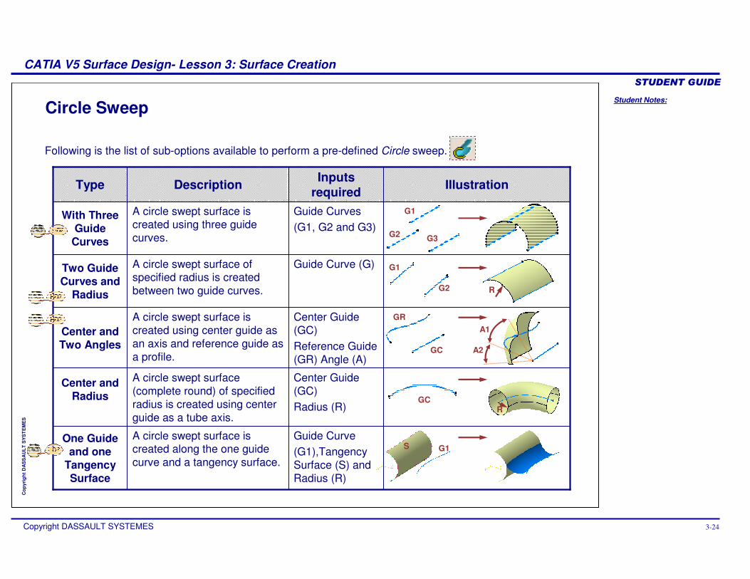
Circle Sweep
Following is the list of sub-options available to perform a pre-defined Circle sweep.
Center Guide (GC)Radius (R)
A circle swept surface (complete round) of specified radius is created using center guide as a tube axis.
Center and Radius
Center Guide (GC)Reference Guide (GR) Angle (A)
A circle swept surface is created using center guide as an axis and reference guide as a profile.
Center and Two Angles
Guide Curve (G1),Tangency Surface (S) and Radius (R)
A circle swept surface is created along the one guide curve and a tangency surface.
One Guide and one
Tangency Surface
Guide Curve (G)A circle swept surface of specified radius is created between two guide curves.
Two Guide Curves and
Radius
Guide Curves(G1, G2 and G3)
A circle swept surface is created using three guide curves.
With Three Guide
Curves
IllustrationInputs requiredDescriptionType
G1
G2 G3
G1
G2
GR
GC
A1
GC
A2
R
R
G1S
Student Notes:
CATIA V5 Surface Design- Lesson 3: Surface Creation������������
Copyright DASSAULT SYSTEMES 3-25
Cop
yrig
ht D
AS
SA
ULT
SY
ST
EM
ES
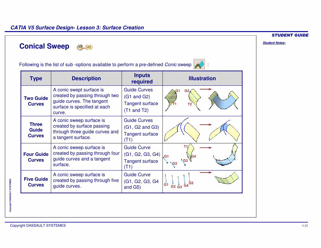
Following is the list of sub -options available to perform a pre-defined Conic sweep :
Conical Sweep
Guide Curve(G1, G2, G3, G4 and G5)
A conic sweep surface is created by passing through five guide curves.
Five Guide Curves
Guide Curve(G1, G2, G3, G4)Tangent surface (T1)
A conic sweep surface is created by passing through four guide curves and a tangent surface.
Four Guide Curves
Guide Curves(G1, G2 and G3)Tangent surface (T1)
A conic sweep surface is created by surface passing through three guide curves and a tangent surface.
Three Guide Curves
Guide Curves(G1 and G2)Tangent surface(T1 and T2)
A conic swept surface is created by passing through two guide curves. The tangent surface is specified at each curve.
Two Guide Curves
IllustrationInputs requiredDescriptionType
G1 G2
T1 T2
T1
G1
G2G3
G4
G1 G2 G3 G4G5
Student Notes:
CATIA V5 Surface Design- Lesson 3: Surface Creation������������
Copyright DASSAULT SYSTEMES 3-26
Cop
yrig
ht D
AS
SA
ULT
SY
ST
EM
ES
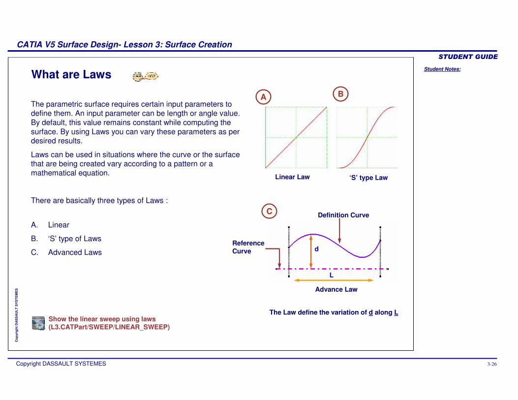
What are Laws
d
L
Advance Law
Reference Curve
Definition Curve
The parametric surface requires certain input parameters to define them. An input parameter can be length or angle value. By default, this value remains constant while computing the surface. By using Laws you can vary these parameters as per desired results.
Laws can be used in situations where the curve or the surface that are being created vary according to a pattern or a mathematical equation.
There are basically three types of Laws :
A. Linear
B. ‘S’ type of Laws
C. Advanced Laws
Linear Law ‘S’ type Law
The Law define the variation of d along L
A
C
B
Show the linear sweep using laws(L3.CATPart/SWEEP/LINEAR_SWEEP)
Student Notes:
CATIA V5 Surface Design- Lesson 3: Surface Creation������������
Copyright DASSAULT SYSTEMES 3-27
Cop
yrig
ht D
AS
SA
ULT
SY
ST
EM
ES
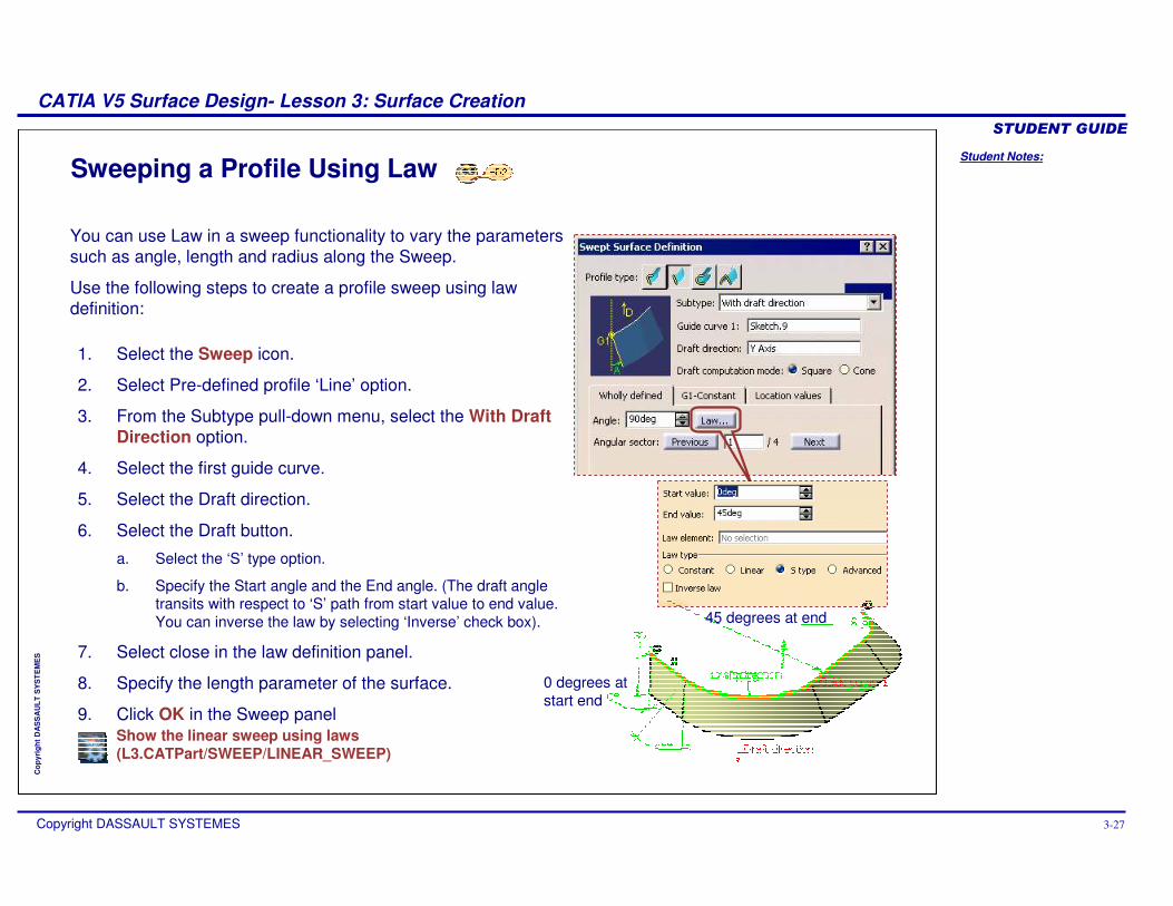
Sweeping a Profile Using Law
You can use Law in a sweep functionality to vary the parameters such as angle, length and radius along the Sweep.
Use the following steps to create a profile sweep using law definition:
1. Select the Sweep icon.
2. Select Pre-defined profile ‘Line’ option.
3. From the Subtype pull-down menu, select the With Draft Direction option.
4. Select the first guide curve.
5. Select the Draft direction.
6. Select the Draft button.
a. Select the ‘S’ type option.
b. Specify the Start angle and the End angle. (The draft angle transits with respect to ‘S’ path from start value to end value. You can inverse the law by selecting ‘Inverse’ check box).
7. Select close in the law definition panel.
8. Specify the length parameter of the surface.
9. Click OK in the Sweep panel
0 degrees at start end
45 degrees at end
Show the linear sweep using laws(L3.CATPart/SWEEP/LINEAR_SWEEP)
Student Notes:
CATIA V5 Surface Design- Lesson 3: Surface Creation������������
Copyright DASSAULT SYSTEMES 3-28
Cop
yrig
ht D
AS
SA
ULT
SY
ST
EM
ES
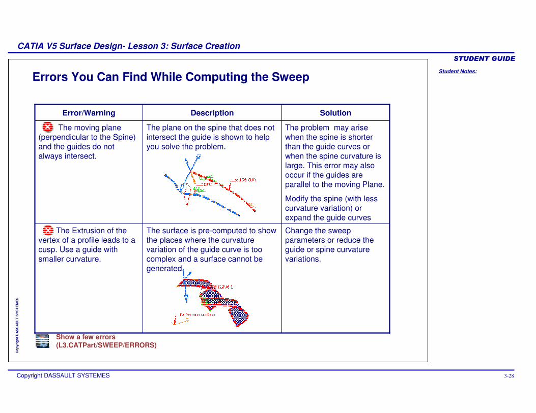
Errors You Can Find While Computing the Sweep
Solution
The problem may arise when the spine is shorter than the guide curves or when the spine curvature is large. This error may also occur if the guides are parallel to the moving Plane.
Modify the spine (with less curvature variation) or expand the guide curves
Error/Warning
The moving plane (perpendicular to the Spine) and the guides do not always intersect.
Change the sweep parameters or reduce the guide or spine curvature variations.
The surface is pre-computed to show the places where the curvature variation of the guide curve is too complex and a surface cannot be generated.
The Extrusion of the vertex of a profile leads to a cusp. Use a guide with smaller curvature.
The plane on the spine that does not intersect the guide is shown to help you solve the problem.
Description
Show a few errors(L3.CATPart/SWEEP/ERRORS)
Student Notes:
CATIA V5 Surface Design- Lesson 3: Surface Creation������������
Copyright DASSAULT SYSTEMES 3-29
Cop
yrig
ht D
AS
SA
ULT
SY
ST
EM
ES
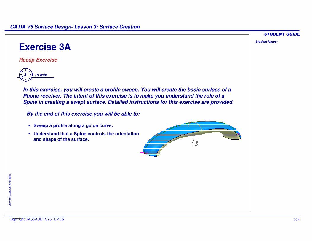
Exercise 3ARecap Exercise
15 min
In this exercise, you will create a profile sweep. You will create the basic surface of a Phone receiver. The intent of this exercise is to make you understand the role of a Spine in creating a swept surface. Detailed instructions for this exercise are provided.
By the end of this exercise you will be able to:
� Sweep a profile along a guide curve.
� Understand that a Spine controls the orientation and shape of the surface.
Student Notes:
CATIA V5 Surface Design- Lesson 3: Surface Creation������������
Copyright DASSAULT SYSTEMES 3-30
Cop
yrig
ht D
AS
SA
ULT
SY
ST
EM
ES
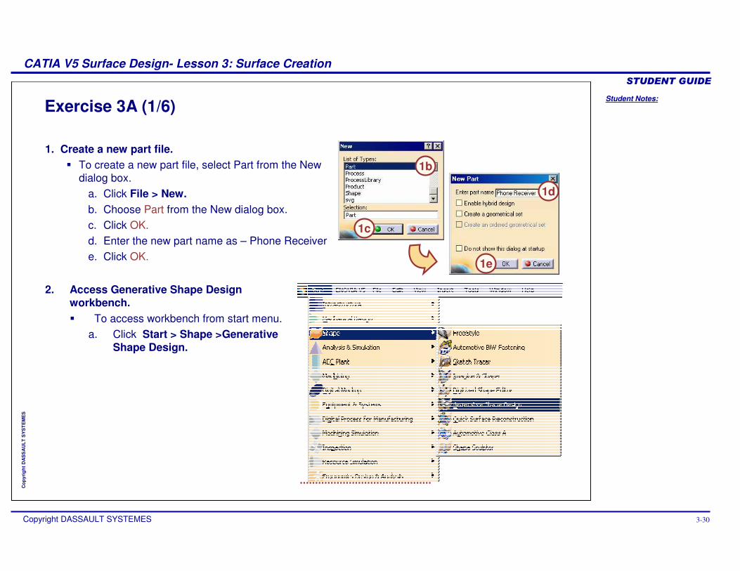
Exercise 3A (1/6)
1. Create a new part file.� To create a new part file, select Part from the New
dialog box.a. Click File > New.b. Choose Part from the New dialog box.c. Click OK.d. Enter the new part name as – Phone Receivere. Click OK.
1b
1c
1d
2. Access Generative Shape Design workbench.� To access workbench from start menu.
a. Click Start > Shape >Generative Shape Design.
1e
Student Notes:
CATIA V5 Surface Design- Lesson 3: Surface Creation������������
Copyright DASSAULT SYSTEMES 3-31
Cop
yrig
ht D
AS
SA
ULT
SY
ST
EM
ES
Exercise 3A (2/6)
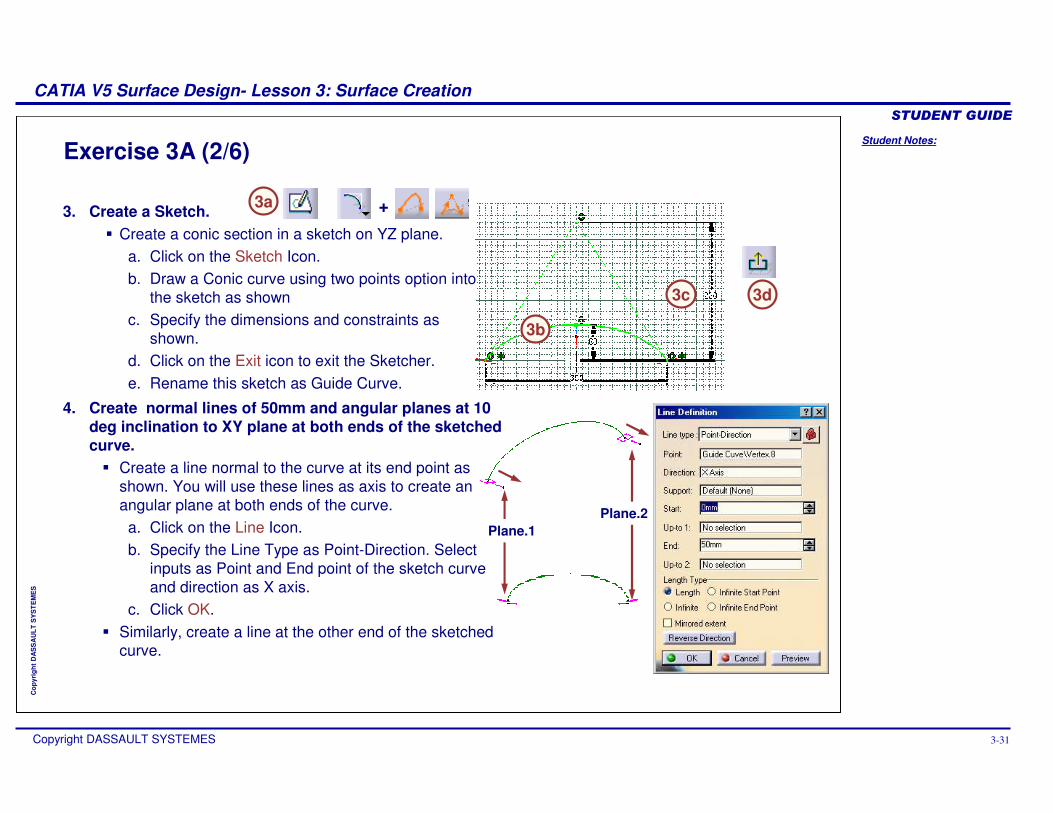
3. Create a Sketch.� Create a conic section in a sketch on YZ plane.
a. Click on the Sketch Icon.b. Draw a Conic curve using two points option into
the sketch as shownc. Specify the dimensions and constraints as
shown. d. Click on the Exit icon to exit the Sketcher.e. Rename this sketch as Guide Curve.
3a
3c
4. Create normal lines of 50mm and angular planes at 10 deg inclination to XY plane at both ends of the sketched curve. � Create a line normal to the curve at its end point as
shown. You will use these lines as axis to create an angular plane at both ends of the curve.
a. Click on the Line Icon.b. Specify the Line Type as Point-Direction. Select
inputs as Point and End point of the sketch curve and direction as X axis.
c. Click OK.� Similarly, create a line at the other end of the sketched
curve.
3d
Plane.1Plane.2
+
3b
Student Notes:
CATIA V5 Surface Design- Lesson 3: Surface Creation������������
Copyright DASSAULT SYSTEMES 3-32
Cop
yrig
ht D
AS
SA
ULT
SY
ST
EM
ES
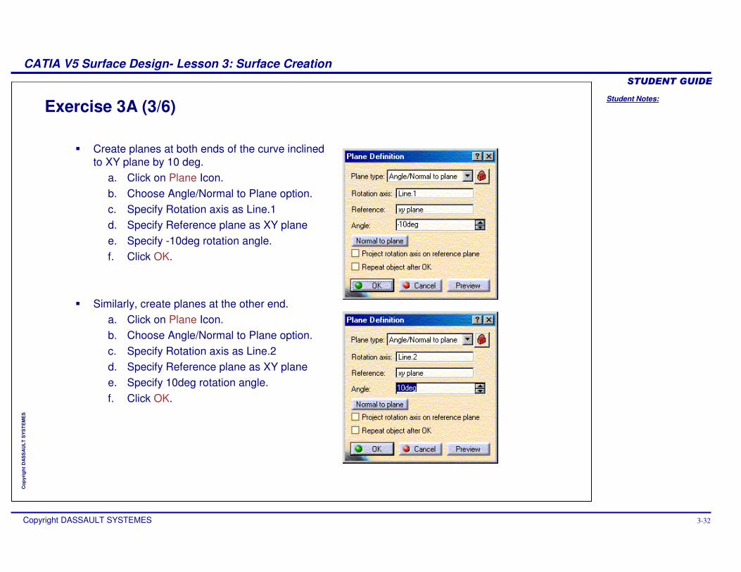
Exercise 3A (3/6)
� Create planes at both ends of the curve inclined to XY plane by 10 deg.
a. Click on Plane Icon.b. Choose Angle/Normal to Plane option.c. Specify Rotation axis as Line.1d. Specify Reference plane as XY planee. Specify -10deg rotation angle.f. Click OK.
� Similarly, create planes at the other end.a. Click on Plane Icon.b. Choose Angle/Normal to Plane option.c. Specify Rotation axis as Line.2d. Specify Reference plane as XY planee. Specify 10deg rotation angle.f. Click OK.
Student Notes:
CATIA V5 Surface Design- Lesson 3: Surface Creation������������
Copyright DASSAULT SYSTEMES 3-33
Cop
yrig
ht D
AS
SA
ULT
SY
ST
EM
ES
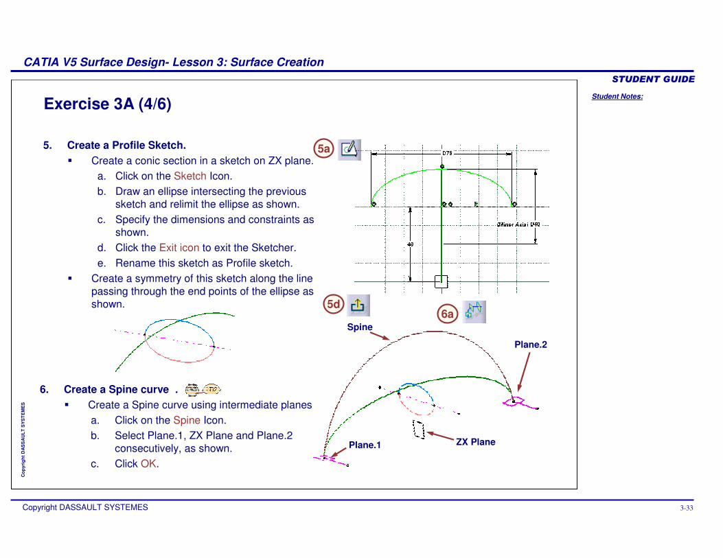
Exercise 3A (4/6)
5. Create a Profile Sketch.� Create a conic section in a sketch on ZX plane.
a. Click on the Sketch Icon.b. Draw an ellipse intersecting the previous
sketch and relimit the ellipse as shown.c. Specify the dimensions and constraints as
shown.d. Click the Exit icon to exit the Sketcher.e. Rename this sketch as Profile sketch.
� Create a symmetry of this sketch along the line passing through the end points of the ellipse as shown.
6. Create a Spine curve .� Create a Spine curve using intermediate planes
a. Click on the Spine Icon.b. Select Plane.1, ZX Plane and Plane.2
consecutively, as shown.c. Click OK.
5a
5d
Plane.1 ZX Plane
Plane.2
Spine6a
Student Notes:
CATIA V5 Surface Design- Lesson 3: Surface Creation������������
Copyright DASSAULT SYSTEMES 3-34
Cop
yrig
ht D
AS
SA
ULT
SY
ST
EM
ES
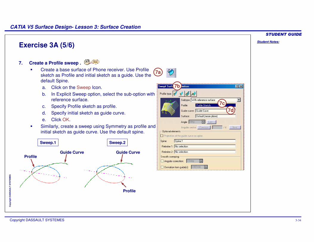
Exercise 3A (5/6)
7. Create a Profile sweep .� Create a base surface of Phone receiver. Use Profile
sketch as Profile and initial sketch as a guide. Use the default Spine.a. Click on the Sweep Icon.b. In Explicit Sweep option, select the sub-option with
reference surface.c. Specify Profile sketch as profile.d. Specify initial sketch as guide curve.e. Click OK.
� Similarly, create a sweep using Symmetry as profile and initial sketch as guide curve. Use the default spine.
7a
7b
7c7d
Sweep.1 Sweep.2
ProfileGuide Curve Guide Curve
Profile
Student Notes:
CATIA V5 Surface Design- Lesson 3: Surface Creation������������
Copyright DASSAULT SYSTEMES 3-35
Cop
yrig
ht D
AS
SA
ULT
SY
ST
EM
ES
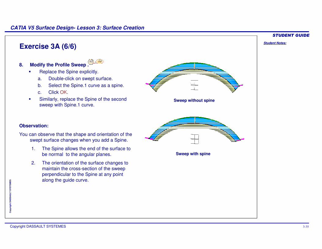
Exercise 3A (6/6)
8. Modify the Profile Sweep .� Replace the Spine explicitly.
a. Double-click on swept surface.b. Select the Spine.1 curve as a spine.c. Click OK.
� Similarly, replace the Spine of the second sweep with Spine.1 curve.
Sweep without spine
Sweep with spine
Observation:
You can observe that the shape and orientation of the swept surface changes when you add a Spine.
1. The Spine allows the end of the surface to be normal to the angular planes.
2. The orientation of the surface changes to maintain the cross-section of the sweep perpendicular to the Spine at any point along the guide curve.
Student Notes:
CATIA V5 Surface Design- Lesson 3: Surface Creation������������
Copyright DASSAULT SYSTEMES 3-36
Cop
yrig
ht D
AS
SA
ULT
SY
ST
EM
ES
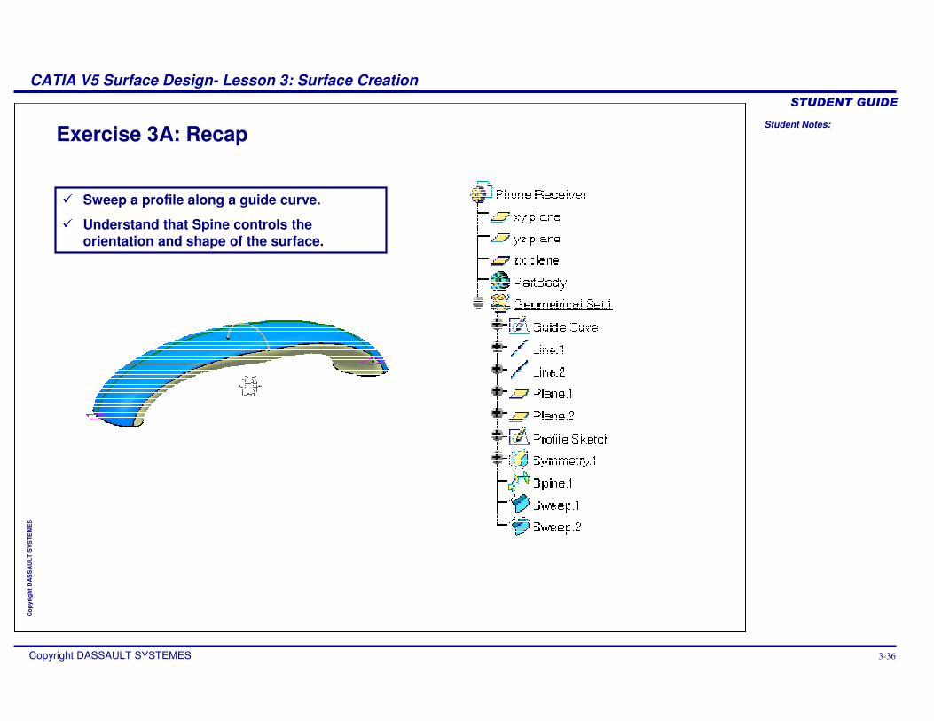
Exercise 3A: Recap
� Sweep a profile along a guide curve.
� Understand that Spine controls the orientation and shape of the surface.
Student Notes:
CATIA V5 Surface Design- Lesson 3: Surface Creation������������
Copyright DASSAULT SYSTEMES 3-37
Cop
yrig
ht D
AS
SA
ULT
SY
ST
EM
ES
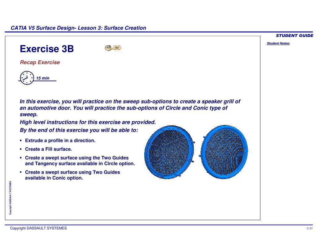
Exercise 3BRecap Exercise
15 min
In this exercise, you will practice on the sweep sub-options to create a speaker grill of an automotive door. You will practice the sub-options of Circle and Conic type of sweep. High level instructions for this exercise are provided.By the end of this exercise you will be able to:
� Extrude a profile in a direction.
� Create a Fill surface.
� Create a swept surface using the Two Guides and Tangency surface available in Circle option.
� Create a swept surface using Two Guides available in Conic option.
Student Notes:
CATIA V5 Surface Design- Lesson 3: Surface Creation������������
Copyright DASSAULT SYSTEMES 3-38
Cop
yrig
ht D
AS
SA
ULT
SY
ST
EM
ES
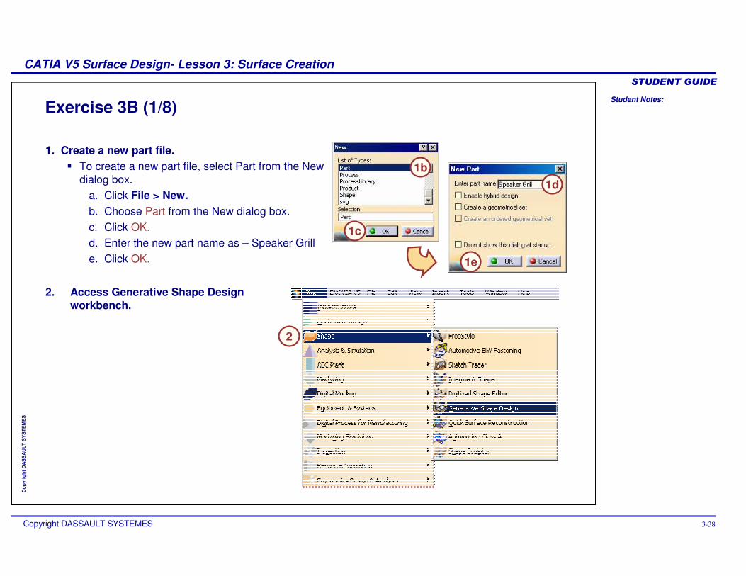
Exercise 3B (1/8)
1. Create a new part file.� To create a new part file, select Part from the New
dialog box.a. Click File > New.b. Choose Part from the New dialog box.c. Click OK.d. Enter the new part name as – Speaker Grille. Click OK.
1b
1c
1d
2. Access Generative Shape Design workbench.
1e
2
Student Notes:
CATIA V5 Surface Design- Lesson 3: Surface Creation������������
Copyright DASSAULT SYSTEMES 3-39
Cop
yrig
ht D
AS
SA
ULT
SY
ST
EM
ES
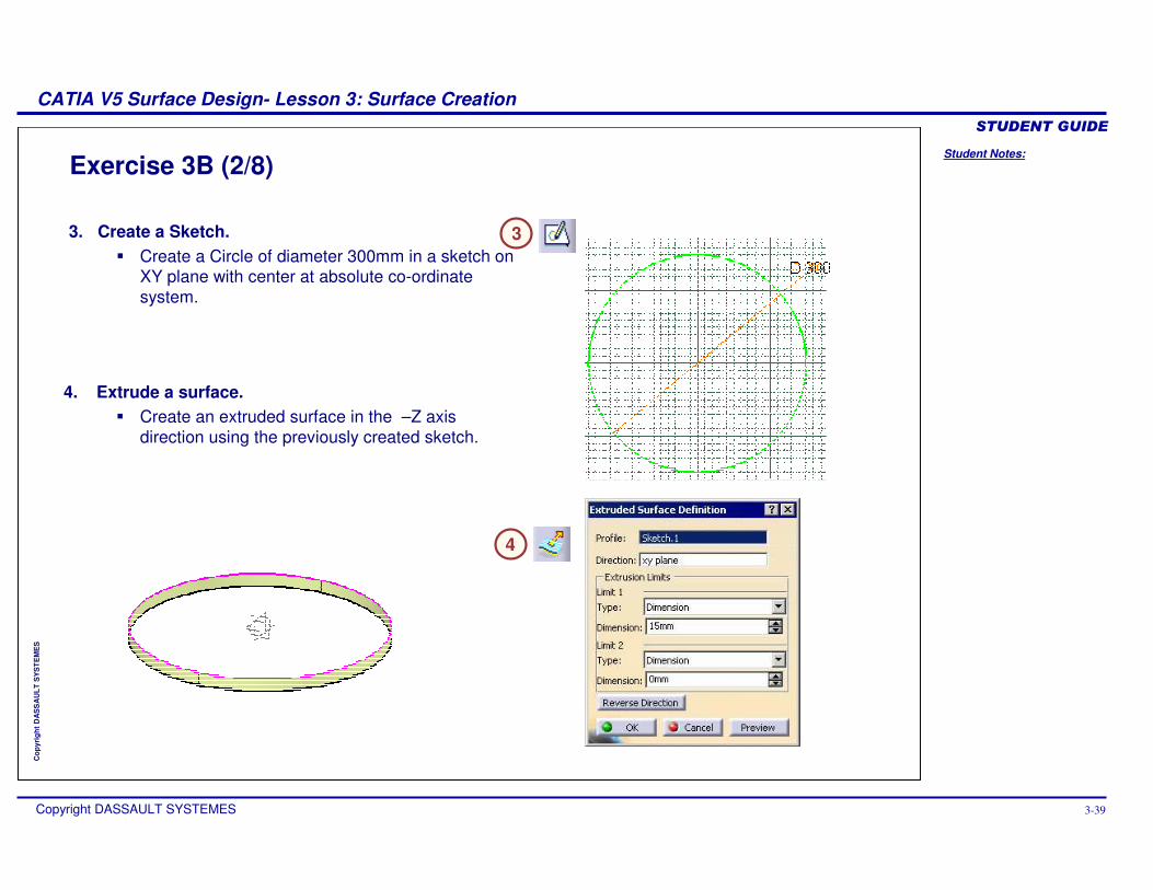
Exercise 3B (2/8)
3. Create a Sketch.� Create a Circle of diameter 300mm in a sketch on
XY plane with center at absolute co-ordinate system.
3
4. Extrude a surface.� Create an extruded surface in the –Z axis
direction using the previously created sketch.
4
Student Notes:
CATIA V5 Surface Design- Lesson 3: Surface Creation������������
Copyright DASSAULT SYSTEMES 3-40
Cop
yrig
ht D
AS
SA
ULT
SY
ST
EM
ES
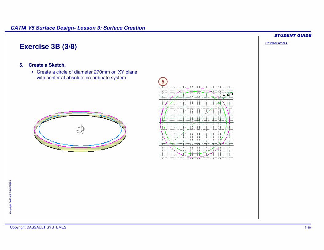
Exercise 3B (3/8)
5. Create a Sketch.� Create a circle of diameter 270mm on XY plane
with center at absolute co-ordinate system.5
Student Notes:
CATIA V5 Surface Design- Lesson 3: Surface Creation������������
Copyright DASSAULT SYSTEMES 3-41
Cop
yrig
ht D
AS
SA
ULT
SY
ST
EM
ES
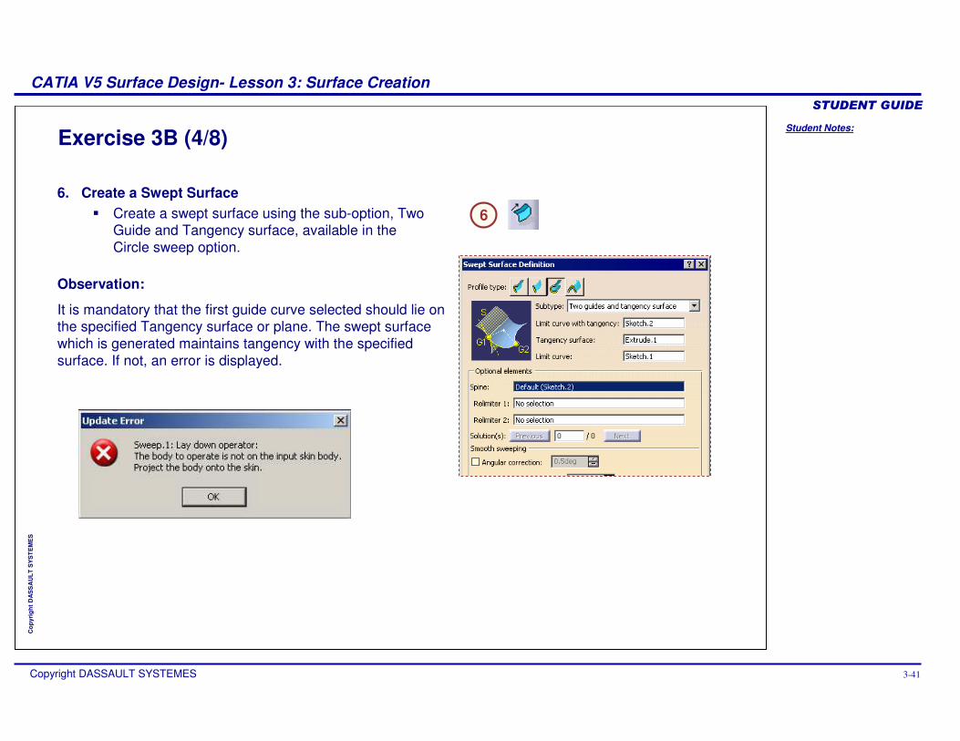
Exercise 3B (4/8)
6. Create a Swept Surface� Create a swept surface using the sub-option, Two
Guide and Tangency surface, available in the Circle sweep option.
Observation:
It is mandatory that the first guide curve selected should lie on the specified Tangency surface or plane. The swept surface which is generated maintains tangency with the specified surface. If not, an error is displayed.
6
Student Notes:
CATIA V5 Surface Design- Lesson 3: Surface Creation������������
Copyright DASSAULT SYSTEMES 3-42
Cop
yrig
ht D
AS
SA
ULT
SY
ST
EM
ES
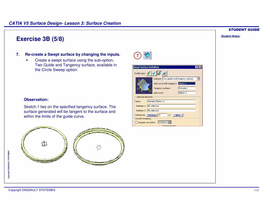
Exercise 3B (5/8)
7. Re-create a Swept surface by changing the inputs.� Create a swept surface using the sub-option,
Two Guide and Tangency surface, available in the Circle Sweep option.
Observation:
Sketch.1 lies on the specified tangency surface. The surface generated will be tangent to the surface and within the limits of the guide curve.
7
Student Notes:
CATIA V5 Surface Design- Lesson 3: Surface Creation������������
Copyright DASSAULT SYSTEMES 3-43
Cop
yrig
ht D
AS
SA
ULT
SY
ST
EM
ES
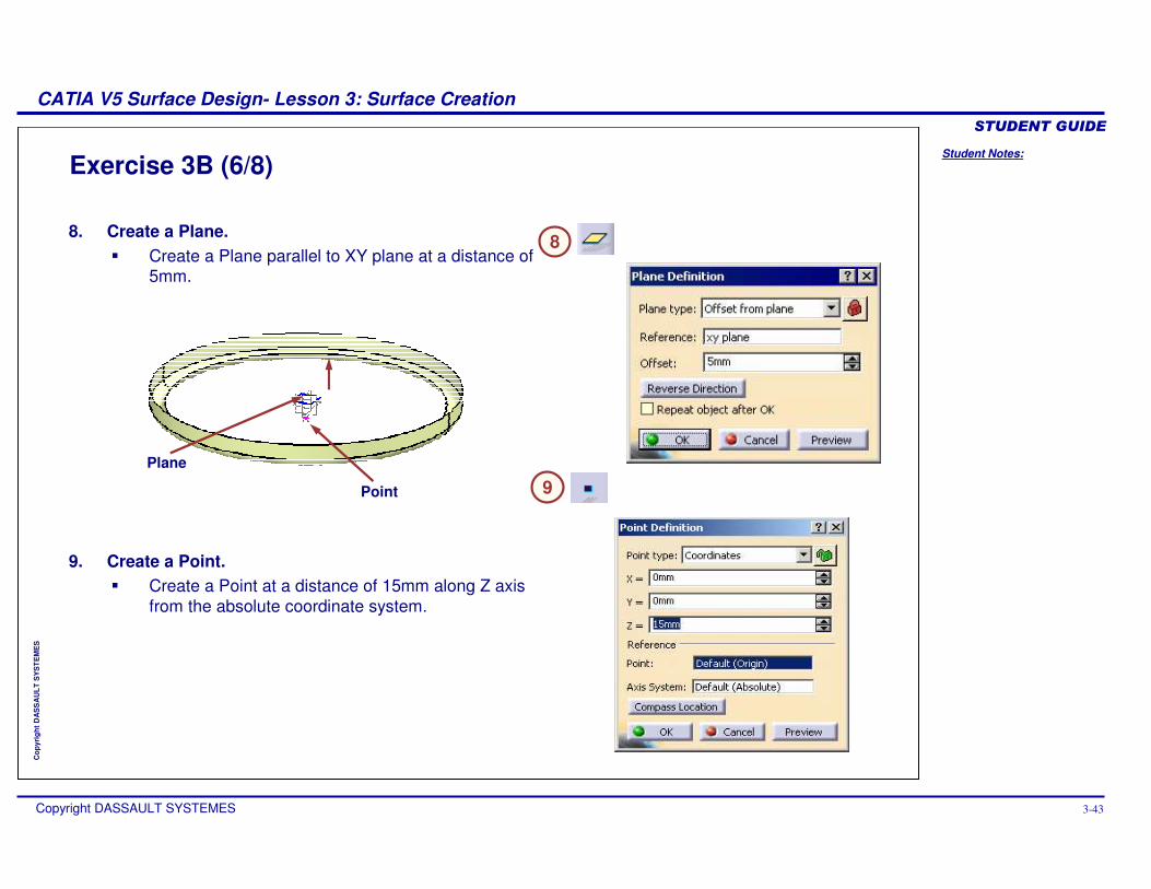
Exercise 3B (6/8)
8. Create a Plane.� Create a Plane parallel to XY plane at a distance of
5mm.
8
9. Create a Point.� Create a Point at a distance of 15mm along Z axis
from the absolute coordinate system.
Point
Plane
9
Student Notes:
CATIA V5 Surface Design- Lesson 3: Surface Creation������������
Copyright DASSAULT SYSTEMES 3-44
Cop
yrig
ht D
AS
SA
ULT
SY
ST
EM
ES
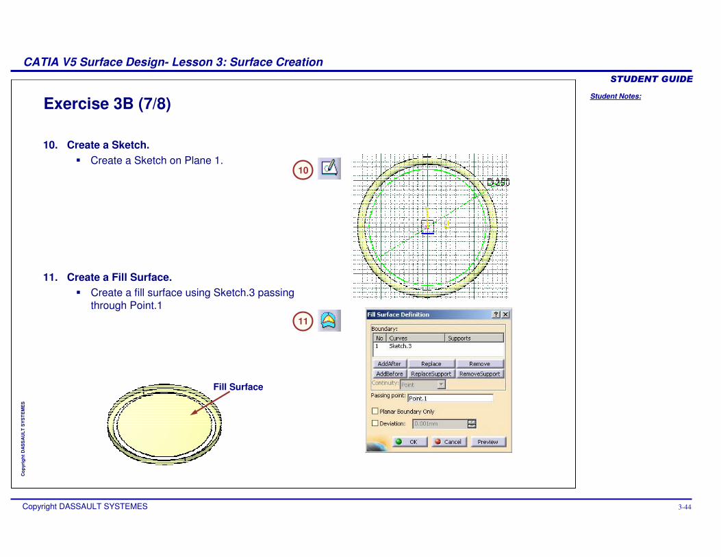
Exercise 3B (7/8)
10
10. Create a Sketch.� Create a Sketch on Plane 1.
11. Create a Fill Surface.� Create a fill surface using Sketch.3 passing
through Point.111
Fill Surface
Student Notes:
CATIA V5 Surface Design- Lesson 3: Surface Creation������������
Copyright DASSAULT SYSTEMES 3-45
Cop
yrig
ht D
AS
SA
ULT
SY
ST
EM
ES
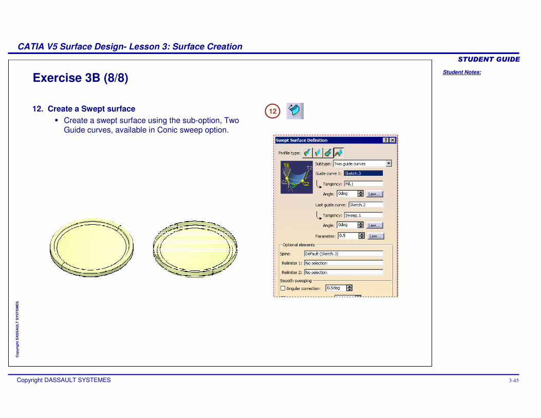
Exercise 3B (8/8)
12. Create a Swept surface� Create a swept surface using the sub-option, Two
Guide curves, available in Conic sweep option.
12
Student Notes:
CATIA V5 Surface Design- Lesson 3: Surface Creation������������
Copyright DASSAULT SYSTEMES 3-46
Cop
yrig
ht D
AS
SA
ULT
SY
ST
EM
ES
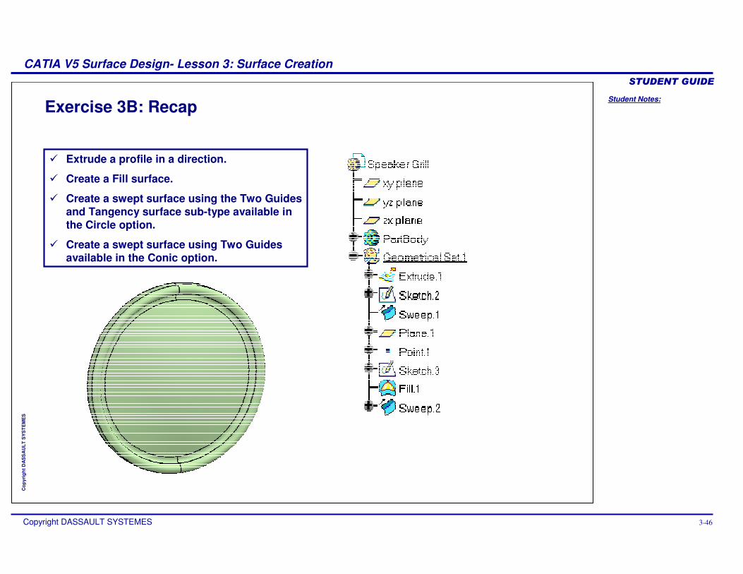
Exercise 3B: Recap
� Extrude a profile in a direction.
� Create a Fill surface.
� Create a swept surface using the Two Guides and Tangency surface sub-type available in the Circle option.
� Create a swept surface using Two Guides available in the Conic option.
Student Notes:
CATIA V5 Surface Design- Lesson 3: Surface Creation������������
Copyright DASSAULT SYSTEMES 3-47
Cop
yrig
ht D
AS
SA
ULT
SY
ST
EM
ES
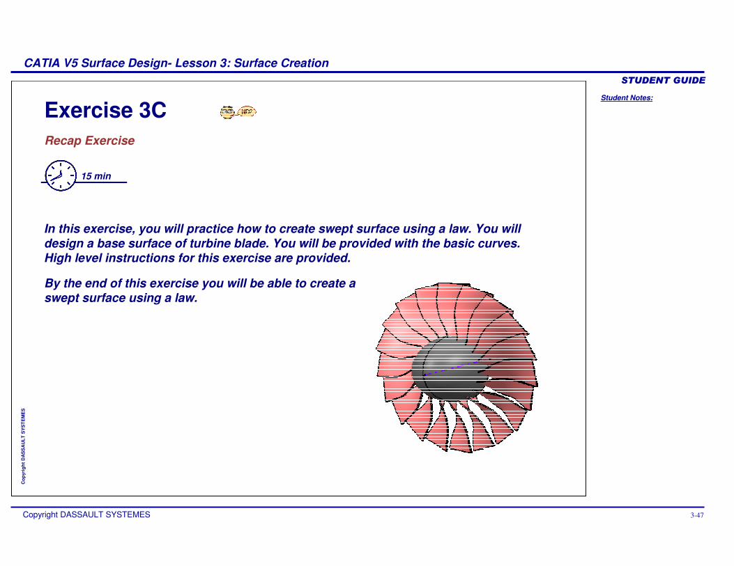
Exercise 3CRecap Exercise
15 min
In this exercise, you will practice how to create swept surface using a law. You will design a base surface of turbine blade. You will be provided with the basic curves. High level instructions for this exercise are provided.
By the end of this exercise you will be able to create a swept surface using a law.
Student Notes:
CATIA V5 Surface Design- Lesson 3: Surface Creation������������
Copyright DASSAULT SYSTEMES 3-48
Cop
yrig
ht D
AS
SA
ULT
SY
ST
EM
ES
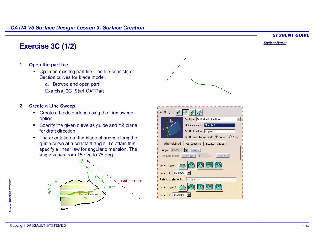
Exercise 3C (1/2)
1. Open the part file. � Open an existing part file. The file consists of
Section curves for blade model.a. Browse and open part:Exercise_3C_Start.CATPart
2. Create a Line Sweep.� Create a blade surface using the Line sweep
option.� Specify the given curve as guide and YZ plane
for draft direction.� The orientation of the blade changes along the
guide curve at a constant angle. To attain this specify a linear law for angular dimension. The angle varies from 15 deg to 75 deg.
Student Notes:
CATIA V5 Surface Design- Lesson 3: Surface Creation������������
Copyright DASSAULT SYSTEMES 3-49
Cop
yrig
ht D
AS
SA
ULT
SY
ST
EM
ES
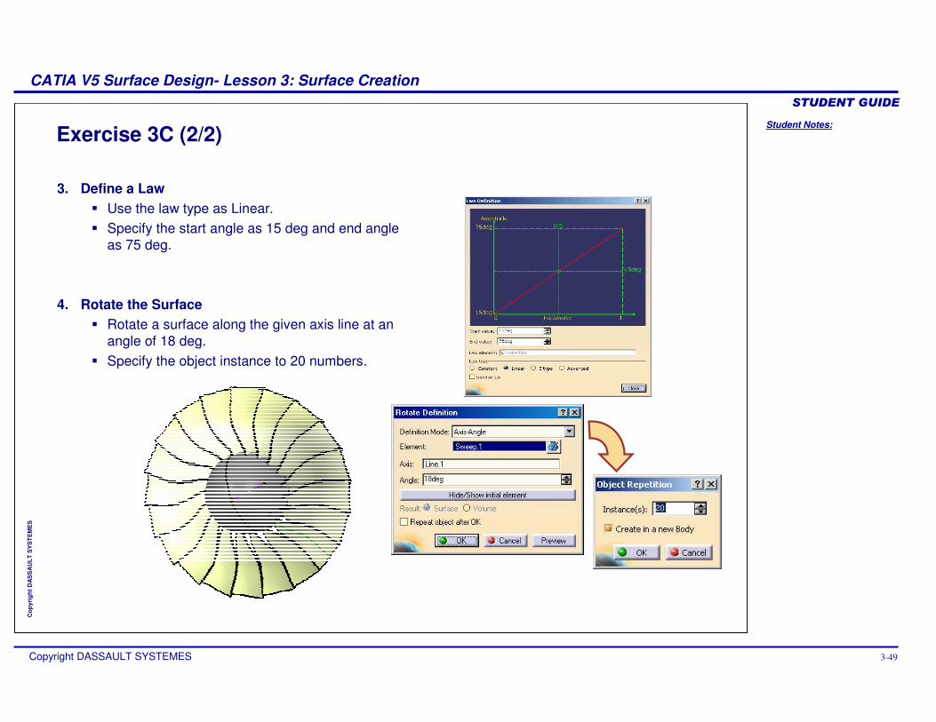
Exercise 3C (2/2)
3. Define a Law� Use the law type as Linear.� Specify the start angle as 15 deg and end angle
as 75 deg.
4. Rotate the Surface� Rotate a surface along the given axis line at an
angle of 18 deg.� Specify the object instance to 20 numbers.
Student Notes:
CATIA V5 Surface Design- Lesson 3: Surface Creation������������
Copyright DASSAULT SYSTEMES 3-50
Cop
yrig
ht D
AS
SA
ULT
SY
ST
EM
ES
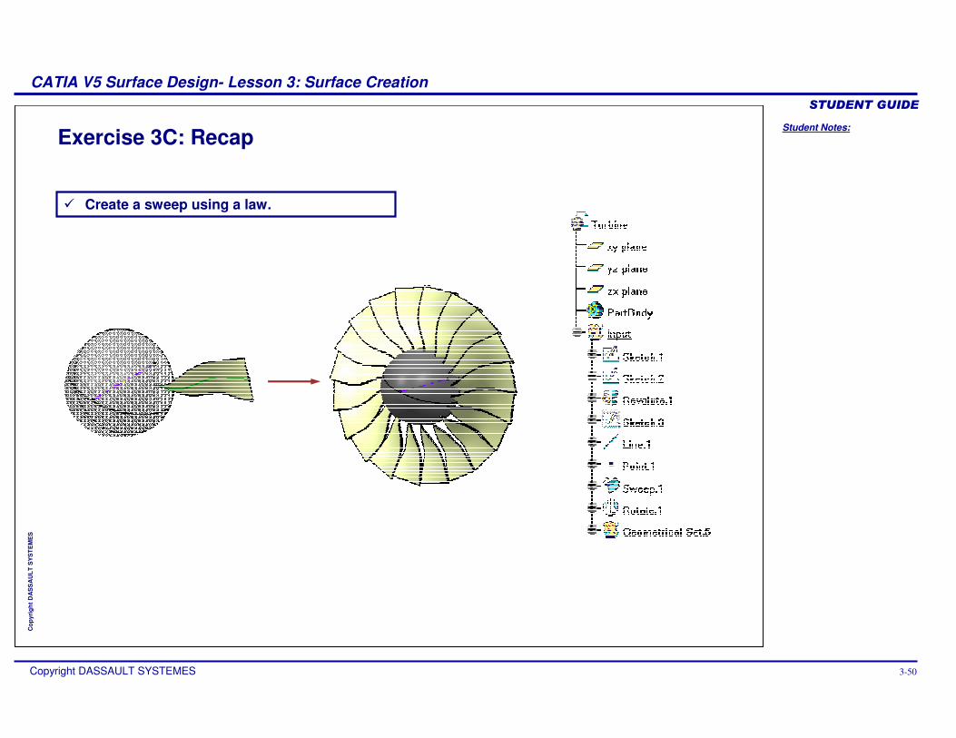
Exercise 3C: Recap
� Create a sweep using a law.
Student Notes:
CATIA V5 Surface Design- Lesson 3: Surface Creation������������
Copyright DASSAULT SYSTEMES 3-51
Cop
yrig
ht D
AS
SA
ULT
SY
ST
EM
ES
Step 4: Create a Multi-Section Surface
In this section you will learn to create Multi-Section Surface.
Use the following steps :
1. Choice of Surfaces 2. Extruding or Revolving a
Profile3. Sweep a Profile
4. Create Multi-Section Surface
5. Create an Adaptive Sweep Surface
Student Notes:
CATIA V5 Surface Design- Lesson 3: Surface Creation������������
Copyright DASSAULT SYSTEMES 3-52
Cop
yrig
ht D
AS
SA
ULT
SY
ST
EM
ES
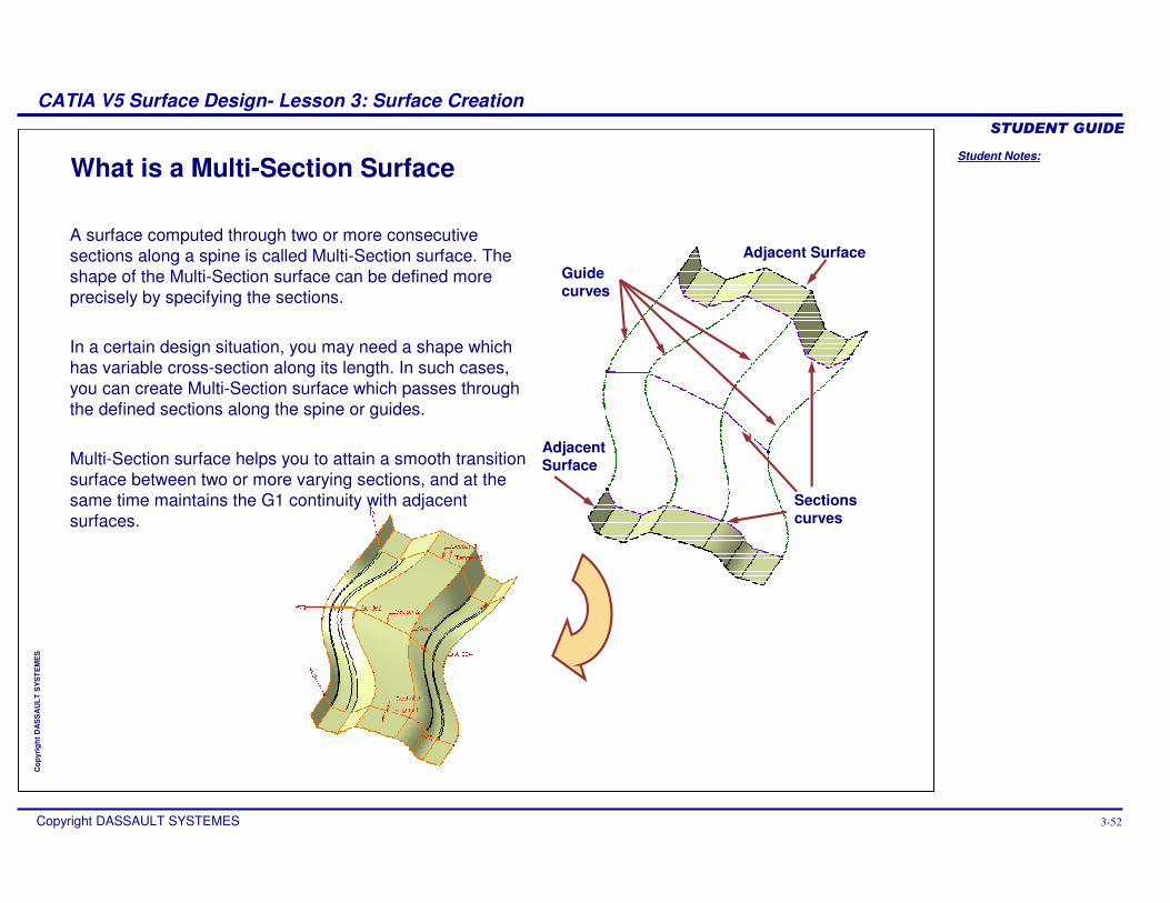
What is a Multi-Section Surface
A surface computed through two or more consecutive sections along a spine is called Multi-Section surface. The shape of the Multi-Section surface can be defined more precisely by specifying the sections.
In a certain design situation, you may need a shape which has variable cross-section along its length. In such cases, you can create Multi-Section surface which passes through the defined sections along the spine or guides.
Multi-Section surface helps you to attain a smooth transition surface between two or more varying sections, and at the same time maintains the G1 continuity with adjacent surfaces.
Sections curves
Guide curves
Adjacent Surface
Adjacent Surface
Student Notes:
CATIA V5 Surface Design- Lesson 3: Surface Creation������������
Copyright DASSAULT SYSTEMES 3-53
Cop
yrig
ht D
AS
SA
ULT
SY
ST
EM
ES
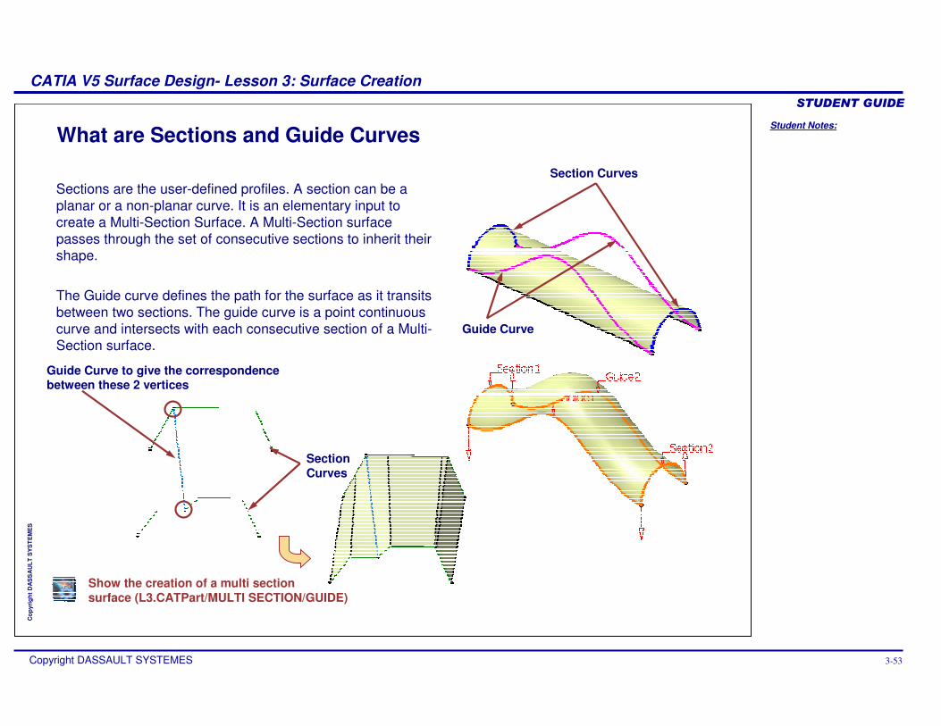
What are Sections and Guide Curves
Sections are the user-defined profiles. A section can be a planar or a non-planar curve. It is an elementary input to create a Multi-Section Surface. A Multi-Section surface passes through the set of consecutive sections to inherit their shape.
The Guide curve defines the path for the surface as it transits between two sections. The guide curve is a point continuous curve and intersects with each consecutive section of a Multi-Section surface.
Section Curves
Guide Curve
Guide Curve to give the correspondence between these 2 vertices
Section Curves
Show the creation of a multi section surface (L3.CATPart/MULTI SECTION/GUIDE)
Student Notes:
CATIA V5 Surface Design- Lesson 3: Surface Creation������������
Copyright DASSAULT SYSTEMES 3-54
Cop
yrig
ht D
AS
SA
ULT
SY
ST
EM
ES
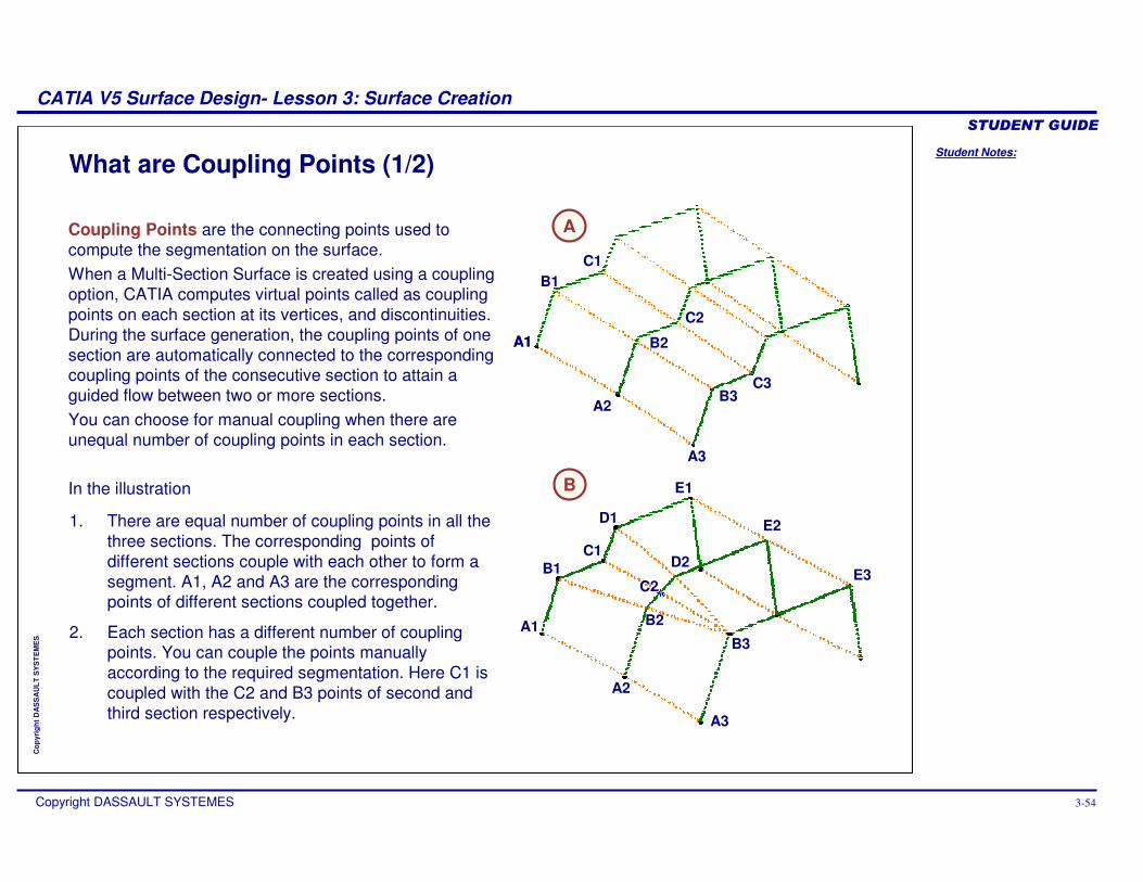
What are Coupling Points (1/2)
Coupling Points are the connecting points used to compute the segmentation on the surface.When a Multi-Section Surface is created using a coupling option, CATIA computes virtual points called as coupling points on each section at its vertices, and discontinuities. During the surface generation, the coupling points of one section are automatically connected to the corresponding coupling points of the consecutive section to attain a guided flow between two or more sections.You can choose for manual coupling when there are unequal number of coupling points in each section.
In the illustration
A
B
1. There are equal number of coupling points in all the three sections. The corresponding points of different sections couple with each other to form a segment. A1, A2 and A3 are the corresponding points of different sections coupled together.
2. Each section has a different number of coupling points. You can couple the points manually according to the required segmentation. Here C1 is coupled with the C2 and B3 points of second and third section respectively.
A1A1
A2
A3
B1
B2
B3
C1
C3
C2
A1
A2
A3
B1
B2
B3
C1
C2
D1
D2
E1
E2
E3
Student Notes:
CATIA V5 Surface Design- Lesson 3: Surface Creation������������
Copyright DASSAULT SYSTEMES 3-55
Cop
yrig
ht D
AS
SA
ULT
SY
ST
EM
ES
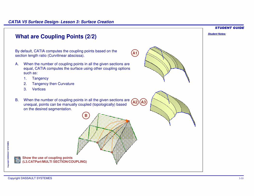
What are Coupling Points (2/2)
A. When the number of coupling points in all the given sections areequal, CATIA computes the surface using other coupling options such as:1. Tangency2. Tangency then Curvature3. Vertices
B. When the number of coupling points in all the given sections areunequal, points can be manually coupled (topologically) based on the desired segmentation.
A2
By default, CATIA computes the coupling points based on the section length ratio (Curvilinear abscissa).
B
A1
A3
Show the use of coupling points(L3.CATPart/MULTI SECTION/COUPLING)
Student Notes:
CATIA V5 Surface Design- Lesson 3: Surface Creation������������
Copyright DASSAULT SYSTEMES 3-56
Cop
yrig
ht D
AS
SA
ULT
SY
ST
EM
ES
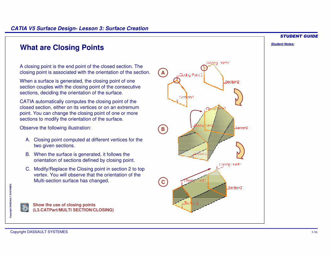
What are Closing Points
A. Closing point computed at different vertices for the two given sections.
B. When the surface is generated, it follows the orientation of sections defined by closing point.
C. Modify/Replace the Closing point in section 2 to top vertex. You will observe that the orientation of the Multi-section surface has changed.
A
B
C
A closing point is the end point of the closed section. The closing point is associated with the orientation of the section.
When a surface is generated, the closing point of one section couples with the closing point of the consecutive sections, deciding the orientation of the surface.
CATIA automatically computes the closing point of the closed section, either on its vertices or on an extremum point. You can change the closing point of one or more sections to modify the orientation of the surface.
Observe the following illustration:
Show the use of closing points(L3.CATPart/MULTI SECTION/CLOSING)
Student Notes:
CATIA V5 Surface Design- Lesson 3: Surface Creation������������
Copyright DASSAULT SYSTEMES 3-57
Cop
yrig
ht D
AS
SA
ULT
SY
ST
EM
ES
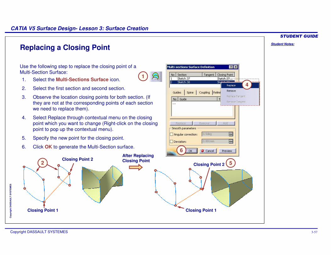
Replacing a Closing Point
1. Select the Multi-Sections Surface icon.
2. Select the first section and second section.
3. Observe the location closing points for both section. (If they are not at the corresponding points of each section we need to replace them).
4. Select Replace through contextual menu on the closing point which you want to change (Right-click on the closing point to pop up the contextual menu).
5. Specify the new point for the closing point.
6. Click OK to generate the Multi-Section surface.
Use the following step to replace the closing point of a Multi-Section Surface:
Closing Point 2
Closing Point 1
After Replacing Closing Point
Closing Point 1
Closing Point 2
1
4
2 5
6
Student Notes:
CATIA V5 Surface Design- Lesson 3: Surface Creation������������
Copyright DASSAULT SYSTEMES 3-58
Cop
yrig
ht D
AS
SA
ULT
SY
ST
EM
ES
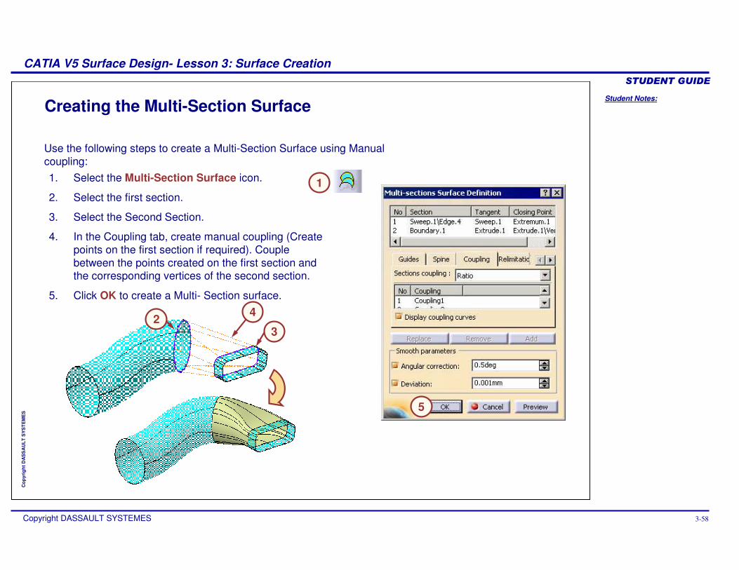
Creating the Multi-Section Surface
1. Select the Multi-Section Surface icon.
2. Select the first section.
3. Select the Second Section.
4. In the Coupling tab, create manual coupling (Create points on the first section if required). Couple between the points created on the first section and the corresponding vertices of the second section.
5. Click OK to create a Multi- Section surface.
Use the following steps to create a Multi-Section Surface using Manual coupling:
1
23
4
5
Student Notes:
CATIA V5 Surface Design- Lesson 3: Surface Creation������������
Copyright DASSAULT SYSTEMES 3-59
Cop
yrig
ht D
AS
SA
ULT
SY
ST
EM
ES
Exercise 3DRecap Exercise
15 min
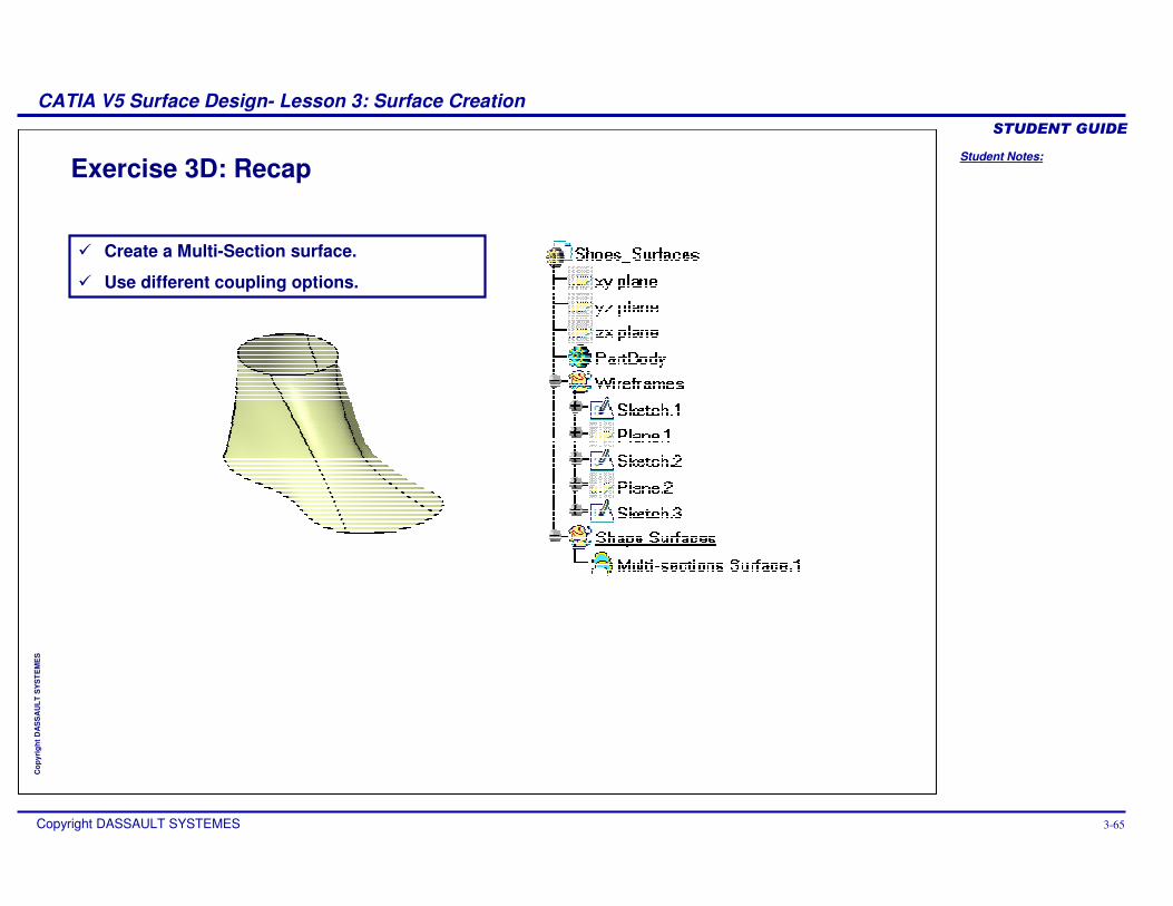
In this exercise, you will practice how to create a Multi-Section surface. You will be given a set of section curves of a shoe. You will create model of a shoe. You will also understand the different coupling options of Multi-Section surfaces. High-level instructions for this exercise are provided.
By the end of this exercise you will be able to:
� Create a Multi-Section surface.
� Use different coupling options.
Student Notes:
CATIA V5 Surface Design- Lesson 3: Surface Creation������������
Copyright DASSAULT SYSTEMES 3-60
Cop
yrig
ht D
AS
SA
ULT
SY
ST
EM
ES
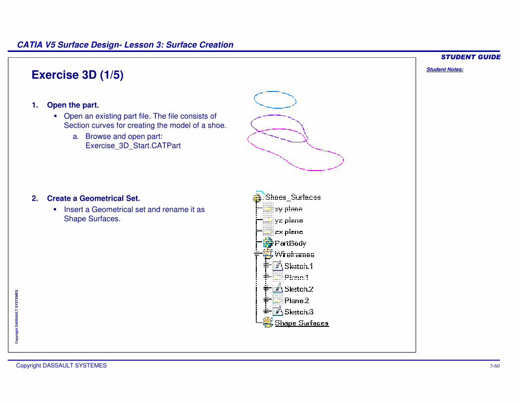
Exercise 3D (1/5)
1. Open the part. � Open an existing part file. The file consists of
Section curves for creating the model of a shoe.a. Browse and open part:
Exercise_3D_Start.CATPart
2. Create a Geometrical Set.� Insert a Geometrical set and rename it as
Shape Surfaces.
Student Notes:
CATIA V5 Surface Design- Lesson 3: Surface Creation������������
Copyright DASSAULT SYSTEMES 3-61
Cop
yrig
ht D
AS
SA
ULT
SY
ST
EM
ES
Exercise 3D (2/5)
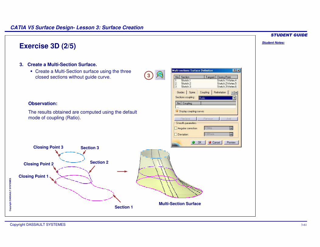
3. Create a Multi-Section Surface. � Create a Multi-Section surface using the three
closed sections without guide curve.
Observation:
The results obtained are computed using the default mode of coupling (Ratio).
Section 1
Section 3
Section 2
Closing Point 3
Closing Point 2
Closing Point 1
3
Multi-Section Surface
Student Notes:
CATIA V5 Surface Design- Lesson 3: Surface Creation������������
Copyright DASSAULT SYSTEMES 3-62
Cop
yrig
ht D
AS
SA
ULT
SY
ST
EM
ES
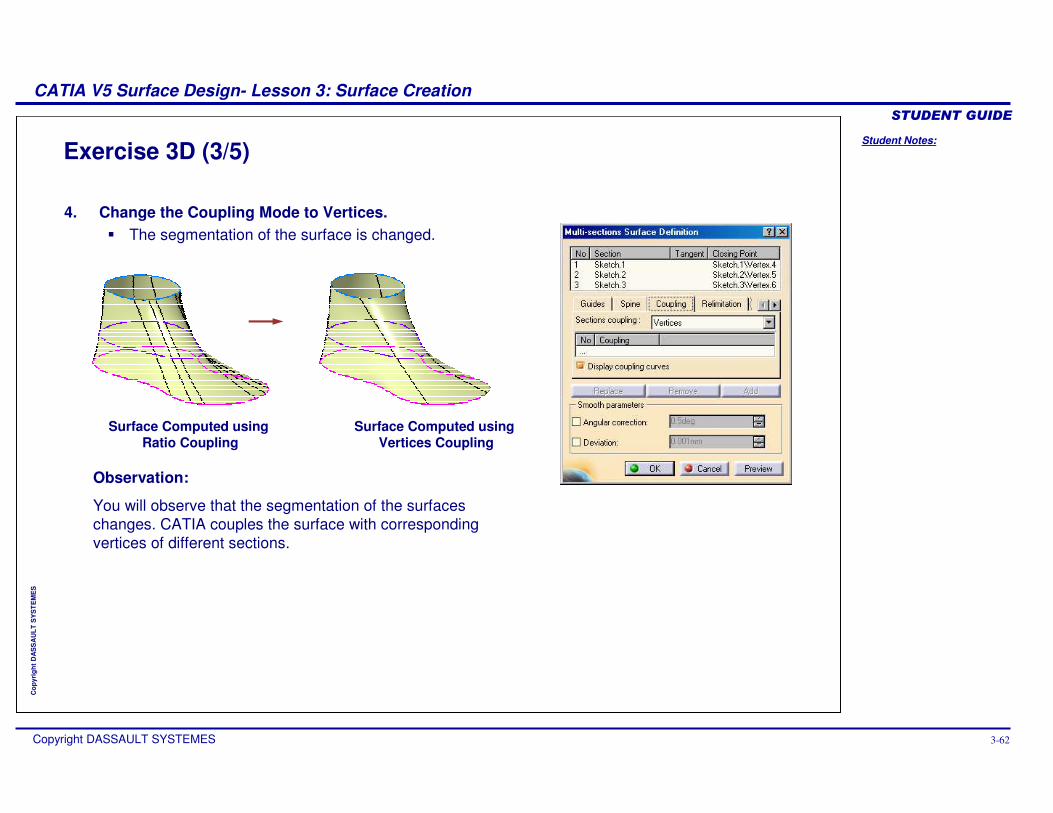
Exercise 3D (3/5)
4. Change the Coupling Mode to Vertices. � The segmentation of the surface is changed.
Observation:
You will observe that the segmentation of the surfaces changes. CATIA couples the surface with corresponding vertices of different sections.
Surface Computed using Ratio Coupling
Surface Computed using Vertices Coupling
Student Notes:
CATIA V5 Surface Design- Lesson 3: Surface Creation������������
Copyright DASSAULT SYSTEMES 3-63
Cop
yrig
ht D
AS
SA
ULT
SY
ST
EM
ES
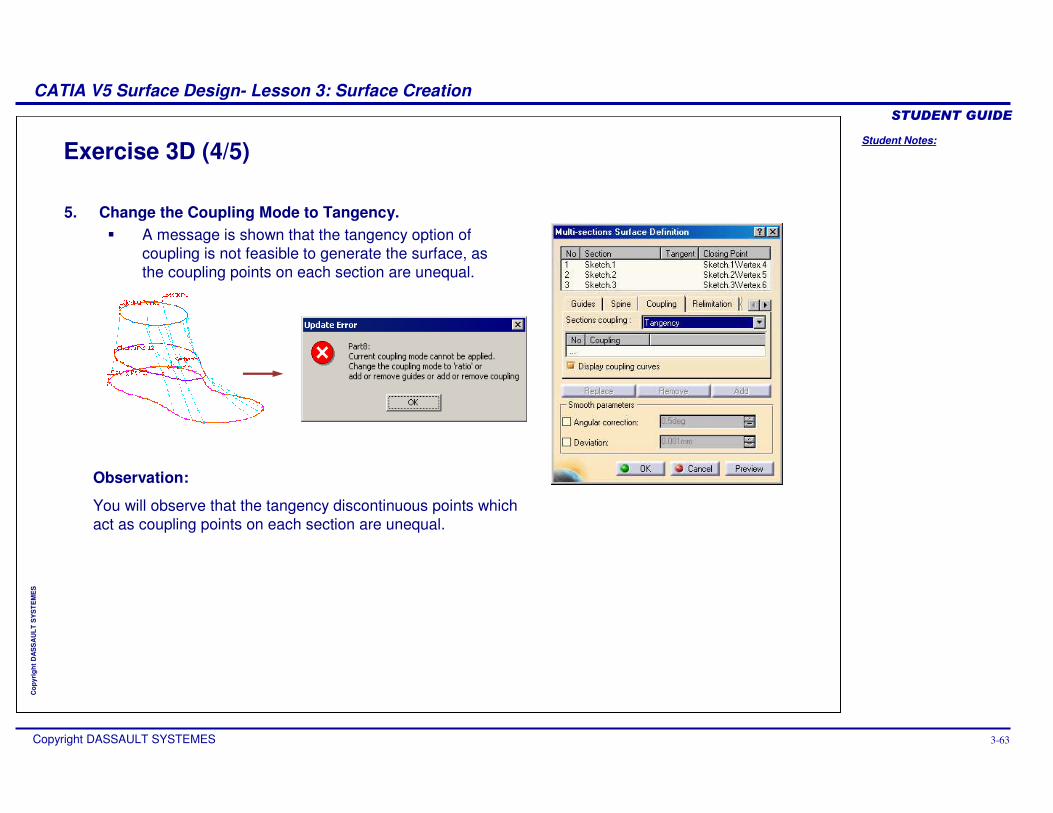
Exercise 3D (4/5)
5. Change the Coupling Mode to Tangency.� A message is shown that the tangency option of
coupling is not feasible to generate the surface, as the coupling points on each section are unequal.
Observation:
You will observe that the tangency discontinuous points which act as coupling points on each section are unequal.
Student Notes:
CATIA V5 Surface Design- Lesson 3: Surface Creation������������
Copyright DASSAULT SYSTEMES 3-64
Cop
yrig
ht D
AS
SA
ULT
SY
ST
EM
ES
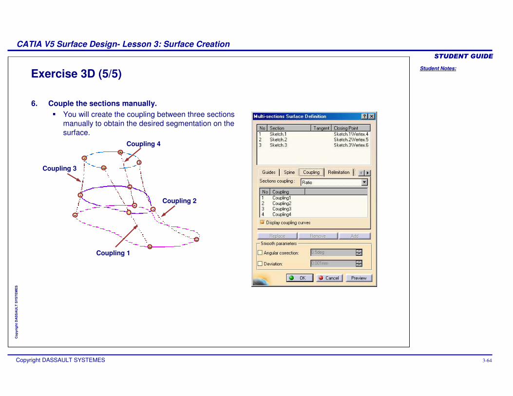
Exercise 3D (5/5)
6. Couple the sections manually.� You will create the coupling between three sections
manually to obtain the desired segmentation on the surface.
Coupling 1
Coupling 2
Coupling 3
Coupling 4
Student Notes:
CATIA V5 Surface Design- Lesson 3: Surface Creation������������
Copyright DASSAULT SYSTEMES 3-65
Cop
yrig
ht D
AS
SA
ULT
SY
ST
EM
ES
Exercise 3D: Recap
� Create a Multi-Section surface.
� Use different coupling options.
Student Notes:
CATIA V5 Surface Design- Lesson 3: Surface Creation������������
Copyright DASSAULT SYSTEMES 3-66
Cop
yrig
ht D
AS
SA
ULT
SY
ST
EM
ES
Step 5: Create an Adaptive Sweep Surface
In this section you will learn to create Adaptive Sweep Surface
Use the following steps to:
1. Choice of Surfaces 2. Extruding or Revolving a Profile3. Sweep a Profile4. Create Multi-Section Surface
5. Create an Adaptive Sweep Surface
Student Notes:
CATIA V5 Surface Design- Lesson 3: Surface Creation������������
Copyright DASSAULT SYSTEMES 3-67
Cop
yrig
ht D
AS
SA
ULT
SY
ST
EM
ES
UserSection .1
UserSection .2
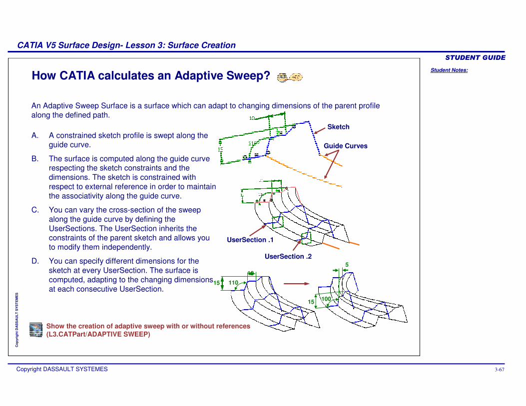
How CATIA calculates an Adaptive Sweep?
10
15 110
An Adaptive Sweep Surface is a surface which can adapt to changing dimensions of the parent profile along the defined path.
A. A constrained sketch profile is swept along the guide curve.
B. The surface is computed along the guide curve respecting the sketch constraints and the dimensions. The sketch is constrained with respect to external reference in order to maintain the associativity along the guide curve.
C. You can vary the cross-section of the sweep along the guide curve by defining the UserSections. The UserSection inherits the constraints of the parent sketch and allows you to modify them independently.
D. You can specify different dimensions for the sketch at every UserSection. The surface is computed, adapting to the changing dimensions at each consecutive UserSection.
Sketch
Guide Curves
15
5
100
Show the creation of adaptive sweep with or without references(L3.CATPart/ADAPTIVE SWEEP)
Student Notes:
CATIA V5 Surface Design- Lesson 3: Surface Creation������������
Copyright DASSAULT SYSTEMES 3-68
Cop
yrig
ht D
AS
SA
ULT
SY
ST
EM
ES
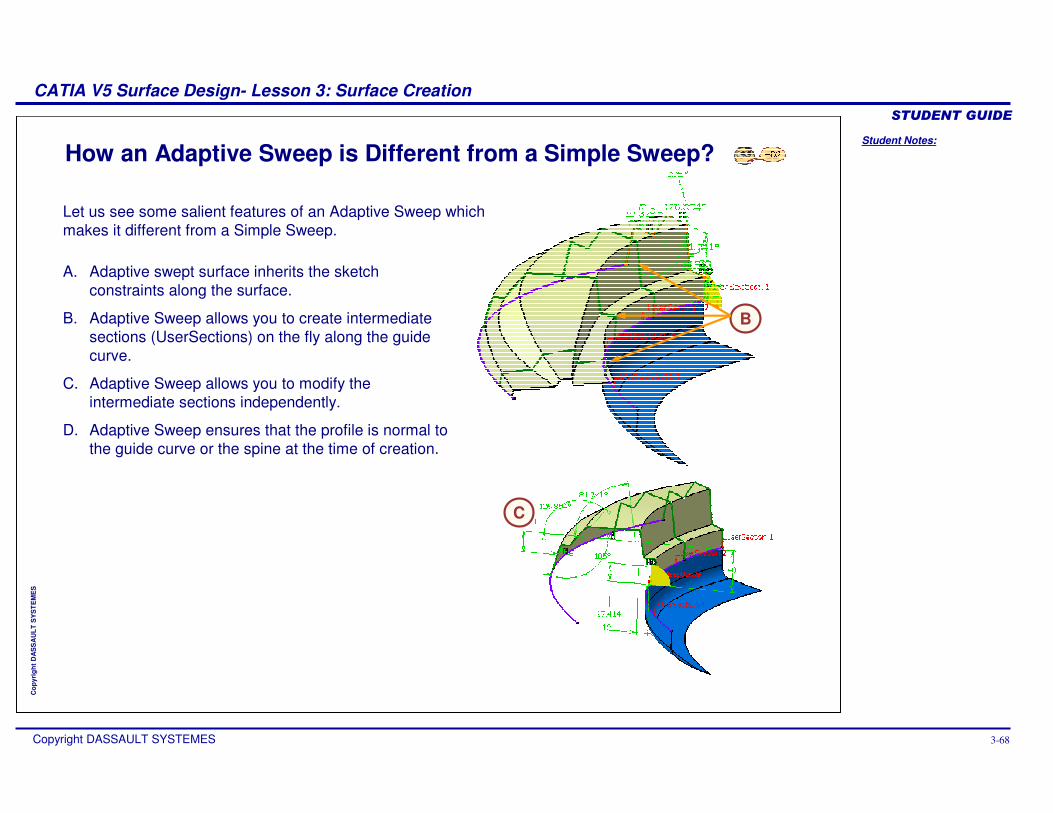
How an Adaptive Sweep is Different from a Simple Sweep?
Let us see some salient features of an Adaptive Sweep which makes it different from a Simple Sweep.
A. Adaptive swept surface inherits the sketch constraints along the surface.
B. Adaptive Sweep allows you to create intermediate sections (UserSections) on the fly along the guide curve.
C. Adaptive Sweep allows you to modify the intermediate sections independently.
D. Adaptive Sweep ensures that the profile is normal to the guide curve or the spine at the time of creation.
B
C
Student Notes:
CATIA V5 Surface Design- Lesson 3: Surface Creation������������
Copyright DASSAULT SYSTEMES 3-69
Cop
yrig
ht D
AS
SA
ULT
SY
ST
EM
ES
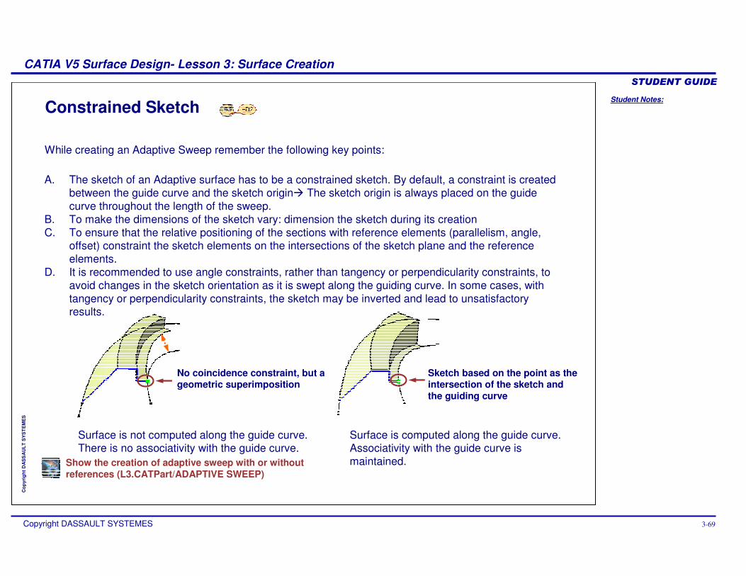
Constrained Sketch
A. The sketch of an Adaptive surface has to be a constrained sketch. By default, a constraint is created between the guide curve and the sketch origin� The sketch origin is always placed on the guide curve throughout the length of the sweep.
B. To make the dimensions of the sketch vary: dimension the sketch during its creationC. To ensure that the relative positioning of the sections with reference elements (parallelism, angle,
offset) constraint the sketch elements on the intersections of the sketch plane and the reference elements.
D. It is recommended to use angle constraints, rather than tangency or perpendicularity constraints, to avoid changes in the sketch orientation as it is swept along the guiding curve. In some cases, with tangency or perpendicularity constraints, the sketch may be inverted and lead to unsatisfactory results.
While creating an Adaptive Sweep remember the following key points:
No coincidence constraint, but a geometric superimposition
Surface is not computed along the guide curve. There is no associativity with the guide curve.
Sketch based on the point as the intersection of the sketch and the guiding curve
Surface is computed along the guide curve. Associativity with the guide curve is maintained.Show the creation of adaptive sweep with or without
references (L3.CATPart/ADAPTIVE SWEEP)
Student Notes:
CATIA V5 Surface Design- Lesson 3: Surface Creation������������
Copyright DASSAULT SYSTEMES 3-70
Cop
yrig
ht D
AS
SA
ULT
SY
ST
EM
ES
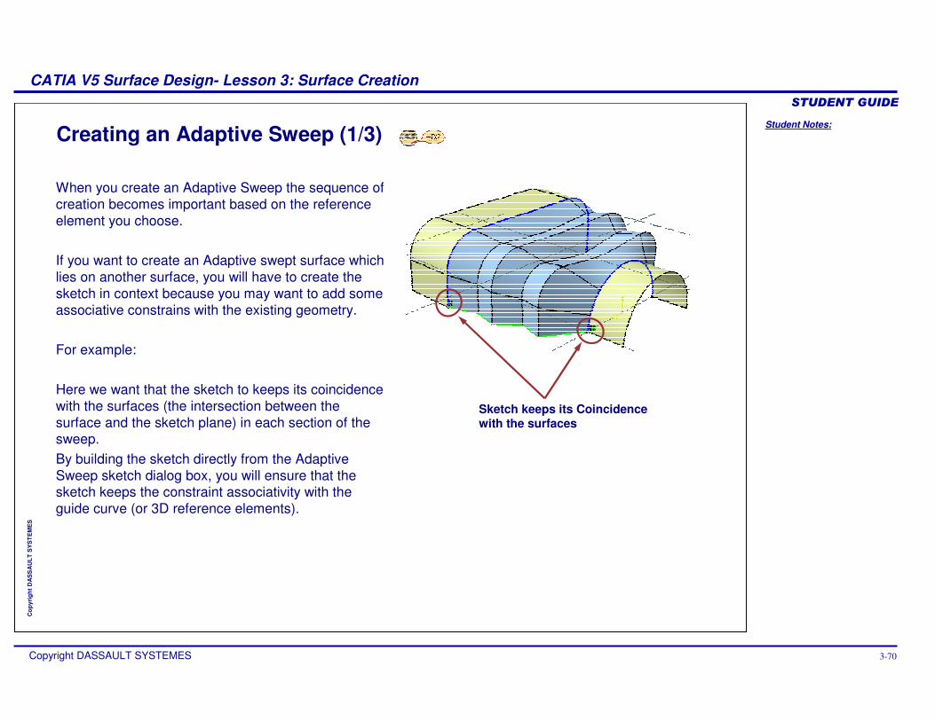
Creating an Adaptive Sweep (1/3)
When you create an Adaptive Sweep the sequence of creation becomes important based on the reference element you choose.
If you want to create an Adaptive swept surface which lies on another surface, you will have to create the sketch in context because you may want to add some associative constrains with the existing geometry.
For example:
Here we want that the sketch to keeps its coincidence with the surfaces (the intersection between the surface and the sketch plane) in each section of the sweep.By building the sketch directly from the Adaptive Sweep sketch dialog box, you will ensure that the sketch keeps the constraint associativity with the guide curve (or 3D reference elements).
Sketch keeps its Coincidence with the surfaces
Student Notes:
CATIA V5 Surface Design- Lesson 3: Surface Creation������������
Copyright DASSAULT SYSTEMES 3-71
Cop
yrig
ht D
AS
SA
ULT
SY
ST
EM
ES
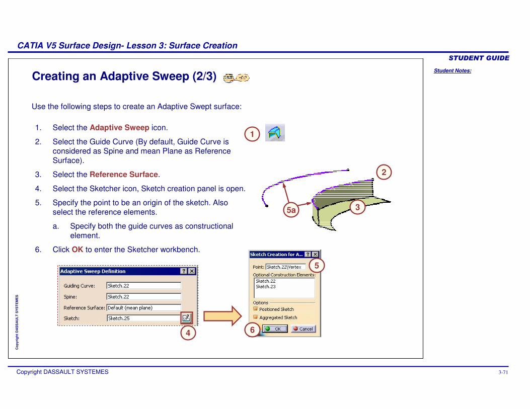
Creating an Adaptive Sweep (2/3)
1. Select the Adaptive Sweep icon.
2. Select the Guide Curve (By default, Guide Curve is considered as Spine and mean Plane as Reference Surface).
3. Select the Reference Surface.
4. Select the Sketcher icon, Sketch creation panel is open.
5. Specify the point to be an origin of the sketch. Also select the reference elements.
a. Specify both the guide curves as constructional element.
6. Click OK to enter the Sketcher workbench.
Use the following steps to create an Adaptive Swept surface:
1
2
4
5
6
5a 3

Student Notes:
CATIA V5 Surface Design- Lesson 3: Surface Creation������������
Copyright DASSAULT SYSTEMES 3-72
Cop
yrig
ht D
AS
SA
ULT
SY
ST
EM
ES
Creating an Adaptive Sweep (3/3)
7. Create the section profile in the sketch as shown and exit the sketch.
8. In the UserSection area in the panel, create the sections along the guide curve by selecting the points on the guide curve.
9. Change the profile dimensions on each section to attain the required shape of the sweep.
10. Click OK to generate the Adaptive Sweep.
Use the following steps to create an Adaptive swept surface (continued…)
7
8
9
10

Student Notes:
CATIA V5 Surface Design- Lesson 3: Surface Creation������������
Copyright DASSAULT SYSTEMES 3-73
Cop
yrig
ht D
AS
SA
ULT
SY
ST
EM
ES
Errors that can be Found While Computing the Sweep
Choose passing points carefully or use the “create section here” tool.
A plane normal to the spine and passing by a chosen point cannot be computed
Section creation failed or sketch not normal to the spine
Solution
Try to avoid using 3D projections or intersections other than the reference element.
Error/Warning
The projection of 3D reference elements may become meaningless along the guide curve and produce unexpected result or sketch inconsistency.
Try to avoid using 3D projections or intersections other than the reference element.
Ensure that the references are intersected throughout the length of the sweep.
When the sketch has used the projections/intersections from the 3D geometry which cannot be referred through out the surface flow along the guide curve, CATIA gives this error on preview.
Error occurred during section computation. Please check if the reference elements or constraint of the sections are usable at the current place.
Whenever you select the point as an input for sketch center in 3D space, ensure that the plane, normal to the guide at that point, intersects the guide.
When the Point specified in the sketch creation dialog box do not intersect with the guide curve, CATIA gives this error.
The Moving Plane (perpendicular to the spine )and guide do not always intersect.
When the sketch has used the projections/intersections from the 3D geometry, which cannot be referred through out the surface flow along the guide curve, CATIA gives this warning on exiting the sketch.
Description

Student Notes:
CATIA V5 Surface Design- Lesson 3: Surface Creation������������
Copyright DASSAULT SYSTEMES 3-74
Cop
yrig
ht D
AS
SA
ULT
SY
ST
EM
ES
To Sum Up
In the following slides you will find a summary of the topics covered in this lesson.

Student Notes:
CATIA V5 Surface Design- Lesson 3: Surface Creation������������
Copyright DASSAULT SYSTEMES 3-75
Cop
yrig
ht D
AS
SA
ULT
SY
ST
EM
ES
Section
OptionalOptionalLoft
Revolve
Sweep
Cylinder
Sphere
Extrude
SpineGuide CurveDirection/AxisProfileInputs
Tools
You can choose a surface depending upon their characteristics and function:
� The surfaces are based on a profile and a direction or revolution axis: Extrude, Cylinder, Revolve and Sphere
� The surface is defined by a few pre-existing sections: Multi-Sections Surface
� A profile (predefined or not) is swept along a guide curve: Sweep or Adaptive Sweep (in order to manage the shape of the profile along the guide curve)
� To fill a gap: Fill� To simulate a thickness on an existing
surface: Offset
You can also choose surface with regards to the wireframe features available. The table shows wireframe required for each type of surface.
Mandatory Not Applicable Loft = Multi-Sections Surface
Choice of Surface

Student Notes:
CATIA V5 Surface Design- Lesson 3: Surface Creation������������
Copyright DASSAULT SYSTEMES 3-76
Cop
yrig
ht D
AS
SA
ULT
SY
ST
EM
ES
In GSD the Sweep tool can be used to sweep following profile types:
Sweep is a surface generated by sweeping a profile along a guide curve with respect to a spine. The profile can be user-defined or pre-defined. The shape and quality of the sweep depends upon the spine.
� Explicit� Line � Circle� Conic
Spine
Profile
Guide
Sweeping a Profile along a Guide Curve with respect to a Spine
Sweeping a Profile

Student Notes:
CATIA V5 Surface Design- Lesson 3: Surface Creation������������
Copyright DASSAULT SYSTEMES 3-77
Cop
yrig
ht D
AS
SA
ULT
SY
ST
EM
ES
Extruding or Revolving a Profile
An Extrude or a Revolve tool uses a Sketch, a 3D curve, an edge of an existing surface or a solid. However self intersecting profiles or profile which intersect with the axis cannot be used. When a sketch is used to create these features, the normal plane is automatically detected (as with an axis, if included in the sketch).
The characteristics of an Extrude and the Cylinder command are similar when a profile is circular.The characteristic of a Revolve and Sphere command are similar when a profile is circular.
Create a Multi-Section SurfaceA surface computed using two or more consecutive sections along a guide curve is called Multi-Section Surface. The guide curve defines the shape of the surface between two sections.
This correspondence between the sections (vertices) can also be specified using coupling points on the sections. During the surface generation, the coupling points of one section are automatically connected to the corresponding coupling points of the consecutive section to attain a guided flow between two or more sections.
Sketch Profile 3D Profile Surface Edge Profile
Solid Edge Profile
Input ����
Profiles That can be Used
Guide Curves
Section Curves
Sections and Guide Curves

Student Notes:
CATIA V5 Surface Design- Lesson 3: Surface Creation������������
Copyright DASSAULT SYSTEMES 3-78
Cop
yrig
ht D
AS
SA
ULT
SY
ST
EM
ES
Create an Adaptive Sweep Surface
An Adaptive Sweep Surface is a surface which can adapt to changing dimensions of the parent profile along the defined path.
While creating an Adaptive Sweep remember the following key points:
� The sketch of an Adaptive surface has to be a constrained sketch. A constraint is created between the guide curve and the sketch origin so that the sketch origin is always placed on the guide curve throughout the length of the sweep.
� To make the dimensions of the sketch vary dimension the sketch during its creation.
� To ensure relative positioning of the sections with reference elements (parallelism, angle, offset) constrain the sketch on the intersections of the sketch plane and the reference elements.
� To use angle constraints, rather than tangency or perpendicularity constraints.
Sketch keeps its Coincidence with the Surfaces

Student Notes:
CATIA V5 Surface Design- Lesson 3: Surface Creation������������
Copyright DASSAULT SYSTEMES 3-79
Cop
yrig
ht D
AS
SA
ULT
SY
ST
EM
ES
Main Tools
1
5
Extrude: Extrudes a user-defined profile in a specified direction.
Revolve: Revolve a user-defined profile around an axis.
Sphere: Creates full or partial spherical surface.
Cylinder: Extrudes an implicitly circular profile in a specified direction.
Sweep: Sweeps a profile along a path.
Adaptive Sweep: Sweeps a parametric profile along a path, allowing the parameters to evolve along the path.
Multi-Section Surface: Surface passing through multiple sections.
Surface Toolbar
7
1
7
2
3
4
6
2 3 4
5 6

Student Notes:
CATIA V5 Surface Design- Lesson 3: Surface Creation������������
Copyright DASSAULT SYSTEMES 3-80
Cop
yrig
ht D
AS
SA
ULT
SY
ST
EM
ES
Exercise 3ERecap Exercise
15 min
In this exercise, you will practice the creation of an Adaptive Sweep surface. You will be creating a base surface for corner part. Detailed instructions for this exercise are provided.
By the end of this exercise you will be able to create an Adaptive Sweep surface.

Student Notes:
CATIA V5 Surface Design- Lesson 3: Surface Creation������������
Copyright DASSAULT SYSTEMES 3-81
Cop
yrig
ht D
AS
SA
ULT
SY
ST
EM
ES
Exercise 3E (1/5)
2. Create set of points on a curve.� You will create five points on the guide curve using
Points and Planes repetition tool.a. Select Point and Plane Repetition icon.b. Specify 5 point and select curve.1.c. Click OK to create the points.
2a
2b
2c
1. Open the part. � Open an existing part file. Browse and open part:
Exercise_3E_Start.CATPart
The Points would be used to create user-sections while defining the sweep
Points

Student Notes:
CATIA V5 Surface Design- Lesson 3: Surface Creation������������
Copyright DASSAULT SYSTEMES 3-82
Cop
yrig
ht D
AS
SA
ULT
SY
ST
EM
ES
Exercise 3E (2/5)
3. Create an Adaptive swept surface.� Create an Adaptive Swept surface using the
given guide curves.a. Click on Adaptive Sweep Icon.b. Select Guide Curve.1 as a Guide Curve
and Spine.c. Select the Support Surface as Reference
Surface.d. Select the sketcher Icon to create a
sketch contextually.e. Select the vertex point of curve.1 as a
reference point of the sketch.f. Select Guide Curve.2 as Optional
Construction Element.g. Click OK to enter the Sketcher.
Guide Curve 1
3e
3f
Guide Curve 2
3a
3b
3g
3c
3b3c
3d

Student Notes:
CATIA V5 Surface Design- Lesson 3: Surface Creation������������
Copyright DASSAULT SYSTEMES 3-83
Cop
yrig
ht D
AS
SA
ULT
SY
ST
EM
ES
Exercise 3E (3/5)
4. Create a sketch profile.� You will create a cross section profile as
shown.
� Exit the Sketcher after you completely constrain the profile.
The Profile would look like this after the sketch
8.0
2.0
4.5

Student Notes:
CATIA V5 Surface Design- Lesson 3: Surface Creation������������
Copyright DASSAULT SYSTEMES 3-84
Cop
yrig
ht D
AS
SA
ULT
SY
ST
EM
ES
Exercise 3E (4/5)
5. Define the UserSections.� Select the previously created Points to
define UserSection.a. Select Point 1 to 5 and the Vertex points
of Curve.1 consecutively as shown to create seven user sections.
Vertex points

Student Notes:
CATIA V5 Surface Design- Lesson 3: Surface Creation������������
Copyright DASSAULT SYSTEMES 3-85
Cop
yrig
ht D
AS
SA
ULT
SY
ST
EM
ES
Exercise 3E (5/5)
6. Edit the User Sections.� You will edit the dimension of each UserSection to obtain
the desired shape of the surface.a. Select the Parameters Tab.b. Select the User-Sections.1c. Change the dimensions of the sketch as shown.
4.518.03User-Section.6
4.516.04User-Section.5
4.520.02User-Section.7
4.512.05User-Section.4
4.58.06User-Section.3
4.55.07User-Section.2
4.52.08User-Section.1
CBAUser Sections A
B
C
� Select OK on the Adaptive Sweep panel to generate the swept surface.

Student Notes:
CATIA V5 Surface Design- Lesson 3: Surface Creation������������
Copyright DASSAULT SYSTEMES 3-86
Cop
yrig
ht D
AS
SA
ULT
SY
ST
EM
ES
Exercise 3E: Recap
� Create an Adaptive Swept surface.

Student Notes:
CATIA V5 Surface Design- Lesson 3: Surface Creation������������
Copyright DASSAULT SYSTEMES 3-87
Cop
yrig
ht D
AS
SA
ULT
SY
ST
EM
ES
Case Study: Surface Creation Recap Exercise
30 min
In this exercise you will create the Door inner components.Recall the design intent of this model:� Create a Door Substrate. The substrate profile needs to be
adaptable for design modifications and changes without replacingthe original input.
� Create a broad cross-section surface for an ‘Arm rest’ attached to the front door for design feasibility study.
� Create a cross-section surface for ‘Key-pad’ (for Electronic control ) at a measured distance from the Arm rest ankle point.
� Create a single merged part by using Arm rest and the key pad components.
� Close the ends of the Arm rest and Key-pad with rounded ends.� Design the door latch.� Design a Map-Pocket with the rounded edges.
Using the techniques mentioned in this lesson and tips from the previous exercises, create the model without detailed instructions.

Student Notes:
CATIA V5 Surface Design- Lesson 3: Surface Creation������������
Copyright DASSAULT SYSTEMES 3-88
Cop
yrig
ht D
AS
SA
ULT
SY
ST
EM
ES
Do It Yourself: Surface Creation (1/3)
1. Open the given part consisting of the wireframes of ‘Car Door’ model, in Generative Shape Design workbench.Browse through the files and open the modelLesson_3_Case_Study_Start.CATPart
2. Create an Adaptive Sweep surface.Create a door substrate from the guides provided using an Adaptive swept surface.
3. Create a Sweep surface.Create a swept surface at the Arm rest and Key pad areas using the Profile and Guide Curve.
The following steps offer hints to guide you through the creation of door part surfaces.
2
3
Adaptive Sweep sketch

Student Notes:
CATIA V5 Surface Design- Lesson 3: Surface Creation������������
Copyright DASSAULT SYSTEMES 3-89
Cop
yrig
ht D
AS
SA
ULT
SY
ST
EM
ES
Do It Yourself: Surface Creation (2/3)
4. Create a single merged part by using Arm rest and the key pad component.Create a Multi-Section Surface between Arm Rest surface and Key Pad surface.Extract the boundary of the swept surfaces and build a Multi-Section surface between the two boundaries as shown.
5. Close the end of the Arm rest and Key-pad with rounded ends.Revolve the boundaries of the swept surface to attain the rounded ends as shown.Extract the boundary of the swept surface and create an axis line to revolve the surface.
4
5

Student Notes:
CATIA V5 Surface Design- Lesson 3: Surface Creation������������
Copyright DASSAULT SYSTEMES 3-90
Cop
yrig
ht D
AS
SA
ULT
SY
ST
EM
ES
Do It Yourself: Surface Creation (3/3)
7
6
Use the shown plane to create the circle sweep of radius 50mm
Connect the edges of the resultant surface
Fill the side part of the pocket
7 7
6. Create a ‘Door latch’.Create a Multi-Section surface using the sections and guide provided.Allow the deviation of 0.01mm in smoothing parameters.
7. Create a ‘Map Pocket feature’.Using the circle sweep option create lower half of the pocket. This surface should be tangent to the blue plane along the Guide curve. Connect the edges of the resultant surface and fill the side part of the pocket.

Student Notes:
CATIA V5 Surface Design- Lesson 3: Surface Creation������������
Copyright DASSAULT SYSTEMES 3-91
Cop
yrig
ht D
AS
SA
ULT
SY
ST
EM
ES
Case Study: Surface Creation Recap
� Create a Door Substrate. The substrate profile needs to be adaptable for design modification and changes without replacing the original input.
� Create a broad cross-section surface for an ‘Arm rest’ attached to the front door for design feasibility study.
� Create a cross-section surface for ‘Key-pad’(for Electronic control ) at a measured distance from the Arm rest ankle point.
� Create a single merged part by using Arm rest and the key pad component.
� Close the end of the Arm rest and Key-pad with rounded end.
� Design the door latch.� Design a Map-Pocket with the rounded
edges.